Chromalox - Sonic Corporation · bulletin PJ304 “Chromalox Design for Heat Tracing Products”...
12
Chromalox ® DIVISION 4 SECTION RT SALES REFERENCE DATE SERVICE REFERENCE Installation, Operation and MAINTENANCE INSTRUCTIONS PJ438-14 161-057884-001 NOVEMBER, 2006 (Supersedes PJ438-13) © 2006 Chromalox, Inc. IMPORTANT GENERAL INSTRUCTIONS These instructions are to be followed when installing Chromalox Heating cables on pipes in ordinary locations. Consult factory for installation of braided cable in hazardous locations. Chromalox has three basic types of heating cables: Self-Regulating, Constant Wattage and Mineral Insulated. Although they are all resistance type cables, they each have different operating charac- teristics. These characteristics may make one type of cable more suitable for a particular application than another. This manual, however, is not intended as a product selection manual. Refer to bulletin PJ304 “Chromalox Design for Heat Tracing Products” for product selection guidelines. Below is a chart highlighting certain characteristics for Chromalox heating cables. Industrial Heating Cable Products INCOMING INSPECTION 1. Open package and visually check for breaks or nicks in the cable jacket. File claim with carrier if any damage is found. 2. Never energize the cable when it’s coiled or on a reel. Test only when it is laid out straight. 3. After removing the cable from the carton or wrapping, check the resistance of the unit from buss wires to braid or metal sheath with a 500VDC megger to assure the cables have not been damaged during shipping and handling. If the cable has no braid or metal sheath, uncoil the cable onto a metal surface and check resistance between the buss wires and the metal sur- face. ELECTRIC SHOCK HAZARD. Any cable with an insu- lation resistance reading less than 10 megohms before installation should not be installed. Contact your local Chromalox representative. 4. The heating cables should be stored in their shipping cartons or on reels in a dry atmosphere until they are ready to be installed. Self-Regulating Constant Wattage Mineral Insulated Hazardous ratings available Yes Yes Yes Usable on plastic pipe Yes* No No Can be cut to length in field Yes Yes No Can be single over lapped Yes No No * Low temperature cables only. UL listing only applies to 3W/Ft. cables Jacket Resistance Wire Binder Buss Wires Module Point Primary Insulation Tinned Copper Braid (Optional) Overcoat Over Braid (Optional) Constant Wattage Self-Regulating Mineral Insulated Heavy-Duty Metal Sheath Densely Compacted Mineral Insulation Twin (Shown) or Single Resistance Wires Overcoat Over Braid (Optional) Tinned Copper Braid (Optional) Jacket Conductive Matrix Buss Wires
-
Upload
duongkhuong -
Category
Documents
-
view
225 -
download
1
Transcript of Chromalox - Sonic Corporation · bulletin PJ304 “Chromalox Design for Heat Tracing Products”...

Chromalox®
DIVISION 4 SECTION RTSALES
REFERENCE
DATE
SERVICE REFERENCEInstallation, Operationand
MAINTENANCE INSTRUCTIONSPJ438-14
161-057884-001NOVEMBER, 2006
(Supersedes PJ438-13)
© 2006 Chromalox, Inc.
IMPORTANT GENERAL INSTRUCTIONSThese instructions are to be followed when installing
Chromalox Heating cables on pipes in ordinary locations. Consultfactory for installation of braided cable in hazardous locations.Chromalox has three basic types of heating cables: Self-Regulating,Constant Wattage and Mineral Insulated. Although they are allresistance type cables, they each have different operating charac-
teristics. These characteristics may make one type of cable moresuitable for a particular application than another. This manual,however, is not intended as a product selection manual. Refer tobulletin PJ304 “Chromalox Design for Heat Tracing Products” forproduct selection guidelines. Below is a chart highlighting certaincharacteristics for Chromalox heating cables.
Industrial Heating Cable Products
INCOMING INSPECTION1. Open package and visually check for breaks or nicks in the
cable jacket. File claim with carrier if any damage is found.2. Never energize the cable when it’s coiled or on a reel. Test
only when it is laid out straight.3. After removing the cable from the carton or wrapping, check
the resistance of the unit from buss wires to braid or metalsheath with a 500VDC megger to assure the cables have notbeen damaged during shipping and handling. If the cable hasno braid or metal sheath, uncoil the cable onto a metal surfaceand check resistance between the buss wires and the metal sur-face.
ELECTRIC SHOCK HAZARD. Any cable with an insu-lation resistance reading less than 10 megohmsbefore installation should not be installed. Contactyour local Chromalox representative.
4. The heating cables should be stored in their shipping cartons oron reels in a dry atmosphere until they are ready to be installed.
Self-Regulating Constant Wattage Mineral Insulated
Hazardous ratings available Yes Yes YesUsable on plastic pipe Yes* No NoCan be cut to length in field Yes Yes NoCan be single over lapped Yes No No
* Low temperature cables only. UL listing only applies to 3W/Ft. cables
Jacket
Resistance Wire
Binder
Buss Wires Module Point
Primary Insulation
Tinned Copper Braid (Optional)Overcoat Over Braid (Optional)
Constant WattageSelf-Regulating Mineral Insulated
Heavy-DutyMetal Sheath
Densely CompactedMineral Insulation
Twin (Shown) or SingleResistance Wires
Overcoat Over Braid(Optional)
Tinned Copper Braid(Optional)
Jacket
Conductive Matrix
Buss Wires

INSTALLATIONA. IMPORTANT — GENERAL NOTES REGARDING
INSTALLATION OF HEAT TRACING SYSTEMS.
FIRE HAZARD. Failure to follow these guidelinescould result in property damage or personal injury.
1. Read this instruction sheet and those enclosed with the acces-sories to familiarize yourself with the products.
2. Selection of heating cable type and rating should be in accor-dance with the procedures located in the “Chromalox DesignGuide for Heat Tracing Products” (PJ304).
3. Ensure all pipes, tanks etc. have been hydrostatically testedprior to the installation of the heating cable.
4. Always install tracing at the 5 or 7 o’clock position on a pipe.5. Installation Guidelines for fire protection systems:
a. For use on insulated UL listed steel schedules 5, 10, 20 and40 standpipe and sprinkler system pipe up to and including6 in. size. Includes use on elbows, tees, flanges, hangersand valves as shown. (show figures of heating cableinstalled to various equipment as mentioned above). ULlisted fiberglass insulation with a minimum k-factor of0.25 BTU/hr -˚F-ft2 -in with weatherproof cladding mustbe used.
b. For systems having piping which connects between build-ings in unheated areas, coolers and freezers.
c. For systems having sprinkler piping that is installed incoolers or freezers where the temperature is -40˚F orgreater.
Not intended to be used as the means to prevent freezing ofsprinkler branch lines including all accessories for these linesand automatic (deluge, preaction, dry pipe, alarm, etc.) valvesas referenced in NFPA 13.
For use in Ordinary Hazard Occupancies only as specified inNFPA 13 the standard for the installation of sprinkler sys-tems.
Fire suppression system heater circuits must be connected tomonitoring equipment. A listed power supply relay with theappropriate voltage coil shall be connected in parallel prior tothe heat tracing (should show figure with typical installation).The output contacts of the listed power supervisory relayshould be connected to a listed fire control panel which hasprovisions for supervisory circuits.
6. Do not attempt to heat trace any piece ofequipment which will not be insulated.
7. Do not install heating cable on equipmentwhich could become hotter than the heatingcable’s maximum exposure temperature.
8. Do not install heating cable in an area or onequipment which contains potentially corro-sive materials without having a suitable pro-tective jacket on the cable.
9. The minimum bending radius for all Chromaloxheating cables is six times the minor diameter.
10. Allow a minimum of 2” between cable runs.11. Always install heat tracing on the outside
radius of elbows.12. Never install heat tracing over expansion
joints without leaving slack in the cable.13. Never use tie-wire or pipe straps to secure
Self-Regulating Maximum Circuit length orConstant Wattage heating cables.
14. Observe all published specifications. Do notexpose cables to temperatures above theirspecified maximums. Do not run cables longerthan specified maximum circuit lengths. Seetable 3 for details.
15. Pumps and small vessels should be heat traced and controlled
with the piping on the inflow end. The cable on the pump orvessel should be physically separate to permit disconnectionduring maintenance or removal.
16. Use aluminum foil tape to cover the heating cable whenever thecable is not in good contact with the pipe (i.e. at supports,valves, pumps, etc.) or whenever its use is specified by theChromalox Design Guide PJ304.
17. Separately controlled circuits should be provided on dead endlegs and closed bypasses.
18. No heat tracing circuit should extend more than two feet beyonda point where two or more pipes join when such junctions per-mit optional flow paths. In such cases, separately controlledtraces should be used.
19. The minimum installation temperature for all Chromalox heat-ing cables is -40˚F (-40˚C).
20. Chromalox Type SRL heating cables are well suited for heattracing plastic pipes. Consult bulletin PJ304 “ChromaloxDesign Guide for Heat Tracing Products” for design recom-mendations. Installation details AD1 through AD17 apply forplastic pipe only when Type SRL heating cable is used. Consultfactory for applications involving other products.
B. INSTALLING A SINGLE RUN OF CABLE ON A PIPE.1. Mount the reel of cable on a holder and place near one end of
the pipe run to be traced. Choose the end from which it will bethe easiest to pay out the cable.
2. Pay out the cable from the reel and loosely string along the pip-ing, making sure the cable is always next to the pipe whencrossing obstacles. For example, if the heater is on the wrongside of a crossing pipe, you will have to restring the cable or cutand splice it.
To prevent damage to cable, avoid such things as:— Pulling the cable over sharp edges.— Forcibly pulling the cable free if it snags while
being paid out.— Allowing the cable to be walked on or subjec-
ed to other abuse which could cause mechan-ical damage.
3. When you reach the end of the circuit, secure the heater cableto the pipe using glass tape or plastic cable tie with a tempera-ture rating compatible with the heater cable.
If this end is to have an end seal installed, remember to leaveabout a foot of extra cable. If it is a power connection, leaveabout two feet of extra heater cable.
4. (If the heater cable is to be spiralled, go to step 4A.)Begin attaching the cable to the pipe about every foot (.3meters).Place the cable on the bottom half of the pipe at the 5 or 7o’clock position. Refer to installation detail ADI. Go to step 5.a. Note the path of the heater cable and the spiral factor of the
design. A simple way to think about spiral factor is: A1.1spiral factor means install 11 feet of heating cable on every10 feet of pipe, etc. At about every 10 feet of pipe, pull therequired amount of cable and let hang in a loop, and attachthe cable to the pipe.
b. Rotate the loops around the pipe until all the slack has beentaken up. Even out the spirals of the heater cable and secureto the pipe as necessary to obtain good contact. The entirecircuit can be installed with hanging loops with the spi-ralling on the pipe being done when you trace the heat sinks.Refer to installation detail AD3.
5. At a heat sink (pipe supports, valves, pumps, reducers, gauges,bucket strainers, etc.), attach the heater cable to the pipe justbefore the heat sink. Refer to the design specs to determine theamount of heater cable you need to install on the heat sink. Pullthis amount of cable into a loop, attach the heater cable on theother side of the heat sink and continue attaching the cabledown the pipe as before.
2

INSTALLATION
6. When you reach the heater cable reel, you should have theheater cable attached all along the pipe, with the correct amountof heater cable pulled in loops at all heat sinks. Attach the cableto the pipe, (leave an extra foot if at an end seal, two feet if at apower connection) and cut the heater cable from the reel.
7. Install the heater cable loops on the heat sinks. Refer to theproper installation detail (AD5-AD12) for a general idea of howto install the cable, but remember:• It is important to get the proper amount of heater cable on
the heat sink, rather than exactly as the detail shows. Thedetail is just a guide.
• Self-Regulating heater cables are very flexible and can besingle overlapped for installation ease. Feel free to use thisfeature when you can.
FIRE HAZARD. Do not overlap constant wattageor mineral insulated heating cables.
• By having the cable installed this way, it can be removedeasily from the heat sink without cutting if access to, orremoval of the heat sink is required.
Note: If a tee is designed into the system, or if you are using two ormore short cable lengths to complete a circuit, allow two or threefeet of each cable to overlap. This will allow flexibility in assem-bling the connection kit and locating it on the pipe.
C. INSTALLING MORE THAN ONE HEATING CABLEON A PIPE.There are two cases where you will need to install more than one heater cable on a pipe:• When the design calls for more than one cable.• When the lines being heat traced are considered important
enough to install a backup (redundant) heat tracing system.
The installation requirements are different for these cases.
1. Installing multiple heater cables for design requirements.The most common multiple cable requirement is two cables on a pipe. Below are the recommended techniques for the twocable systems. They also apply to installations where three ormore cables are to be installed on a pipe.
There are two ways of paying out two heater cables along apipe. The first is to locate two reels of heater cable and supplyone cab from each. This method works for all types of pipingruns.However, it may increase material waste by leaving unusablelengths from two reels. The second way is to supply both cablesfrom one reel. This method is generally the easiest for relative-ly straight, simple piping runs. For each circuit, decide whichmethod to use and then go to the appropriate part below.a. Supplying cable from two reels.
The general procedure here is the same as given earlier, butthere are a few things to do to make sure the system is cor-rectly done.
i. At each heat sink, the easiest thing to do is supply theextra heater called for by the design drawing from onlyone heater cable. This avoids having to measure out halfof the requirement from each cable.
ii. When doing the previous step, leave a small loop othercable at equipment which may be serviced, such aspumps, valves, instruments, etc. This is so both heatercables may be removed enough for future access.
b. Supply heater cables from one reel.The general procedure is the same as given earlier, but thereare a few things to do to make sure the system is correctlydone.i. With this method, a loop is pulled for the entire circuit.
To do this, attach the end of the heater cable to the pipenear the heater cable reel. Remember to leave enoughextra cable for the type of connection to be installed.
ii. Begin pulling the cable off the reel in a large loop down the piping run. Be sure to keep the cable next to the pipe.Moving down the run, continue attaching the cable to thepipe, leaving the side of the loop going back to the reelunattached.
iii.You will want both sides of the loop to be about the same length to avoid future problems. Also, it is easier toinstall the extra cable required at each heat sink from onlyone cable. Therefore, pull the right amount of extra heatercable needed at every second heat sink from the side ofthe loop you are attaching to the pipe. At the remainingserviceable heat sinks (pumps, valves, instruments, etc.)don’t forget to leave a short loop of cable for slack whenaccess to the equipment is needed.
iv.When the end of the piping run is reached, pull the prop-er amount of extra cable for the connection to be installed.
v. Now, begin working the remaining side of the loop back toward the reel, installing it on the pipe and heat sinks asrequired.
2. Installation for Backup (Redundant) Systems.The purpose of a backup system is to provide the proper amountof heat from the second heater cable if there are problems withthe first. Therefore, each cable must be installed so it can do thejob alone. The simplest way to do this is to install the first heatercable as given in Section B. Then, go back and install the back-up heater cable the same way.
There are several things to keep in mind:• The power connections and end seals for the two cables are
often designed to be at opposite ends of the run in a redun-dant system. Remember to leave the proper amount of extracable for the connection to be installed on each cable at thatend.
• On piping one inch IPS or smaller, it can be difficult to apply both heater cables with good contact at all places. Themain thing is to get the correct amount of cable installed.However, try to get as much contact with the piping and heatsinks from both cables as possible.
3

AD5 - Orifice Flange AD6 - Expansion Joint
TYPICAL INSTALLATION DETAIL
4
Metallic Pipe
Tape or BandingHeating CableSelf Regulating
Constant WattageMineral Insulated
Expansion JointFlange Position with Pipe Expanded
Note: Insulate over flanges & orifice plate andweatherseal. All piping must be fully insulatedand weathersealed.
Orifice Plate Tape or Banding
Metallic PipeHeating CableSelf Regulating
Constant WattageMineral Insulated Flexible conduit junction box may be
required if a splice is necessaryConduit connection fitting to be suitable for area clas-sification. Heating cable may be run continuouslythrough the conduit.
Note: All piping must be fully insulated and weathersealed.
AD3 - One Cable-Spiralling Method AD4 - One Run of Cable at Pipe Elbow
AD1 - One Run of Cable AD2 - Two Runs of Cable
Metallic PipeTape or Banding
Heating CableSelf RegulatingConstant WattageMineral Insulated
12”
Typical
Thermal Insulation
45˚
Top
Weatherproof Jacket
Note: Cable located at nominal45˚ below horizontal centerline.
Thermal Insulation
Heating CableSelf RegulatingConstant WattageMineral Insulated Tape or Banding
12”
Typical
Metallic PipeTop
Weatherproof Jacket
Note: Cable located at nominal 45˚ belowhorizontal centerline on either side.
45˚ 45˚
Metallic Pipe
Tape orBanding
Heating CableSelf Regulating, Constant Wattage,Mineral Insulated
12”Typical
Thermal InsulationWeatherproof
Jacket
Pitch
Note:1. Do not spiral if ratioof heater length to pipelength is greater than1.5. Instead, use twocables or choose a high-er wattage heater.
Note:2. Refer to pitch chart in designdata section on circuit drawingfor proper pitch length.
Metallic Pipe
Tape or Banding
Heating CableSelf Regulating
Constant WattageMineral Insulated
Thermal Insulation
Weatherproof Jacket
Note: Heating cable isapplied to the outside (long)radius of the pipe elbow.
SUPPLEMENTAL INSTRUCTIONS FOR ATEX APPLICATIONS1. Do not bend the cable for a length of 300mm from cable gland
inlet.2. Connection and termination of Chromalox cable must be
installed using cable glands and type ‘e’ connection kits asprovided by Chromalox, Inc.
3. The supply circuit to the heating cables must be protected by asafety differential device or equivalent ground fault protection.
4. Chromalox cable minimum installation temp is -30˚C.

TYPICAL INSTALLATION DETAIL
AD7 - Welded Support AD8 - Shoe Support
AD9 - Valve AD10 - Pressure Gauge
Metallic PipeTape or Banding
Heating CableSelf Regulating
Constant WattageMineral Insulated
Note: Pipe Support to be insulated two feetbelow pipe and weathersealed. All pipingmust be fully insulated and weathersealed.
Pipe Support
3”Typical
Metallic Pipe Tape or Banding
Heating CableSelf Regulating
Constant WattageMineral Insulated Note: Insulate and weatherseal support. All pip-
ing must be fully insulated and weathersealed.
Support Shoe
A A
3 inches (Typical)
Section A-A
Tape or Banding
Heating CableSelf RegulatingConstant WattageMineral Insulated
Note: All piping must be fully insulated andweathersealed.
Rear View
Metallic Pipe
Tape or Banding
Heating CableSelf Regulating
Constant WattageMineral Insulated
Note: Completely insulate & weatherseal line andgauge. All piping must be fully insulated andweathersealed.
Front View
Pressure Gauge
Shut-OffValve
5
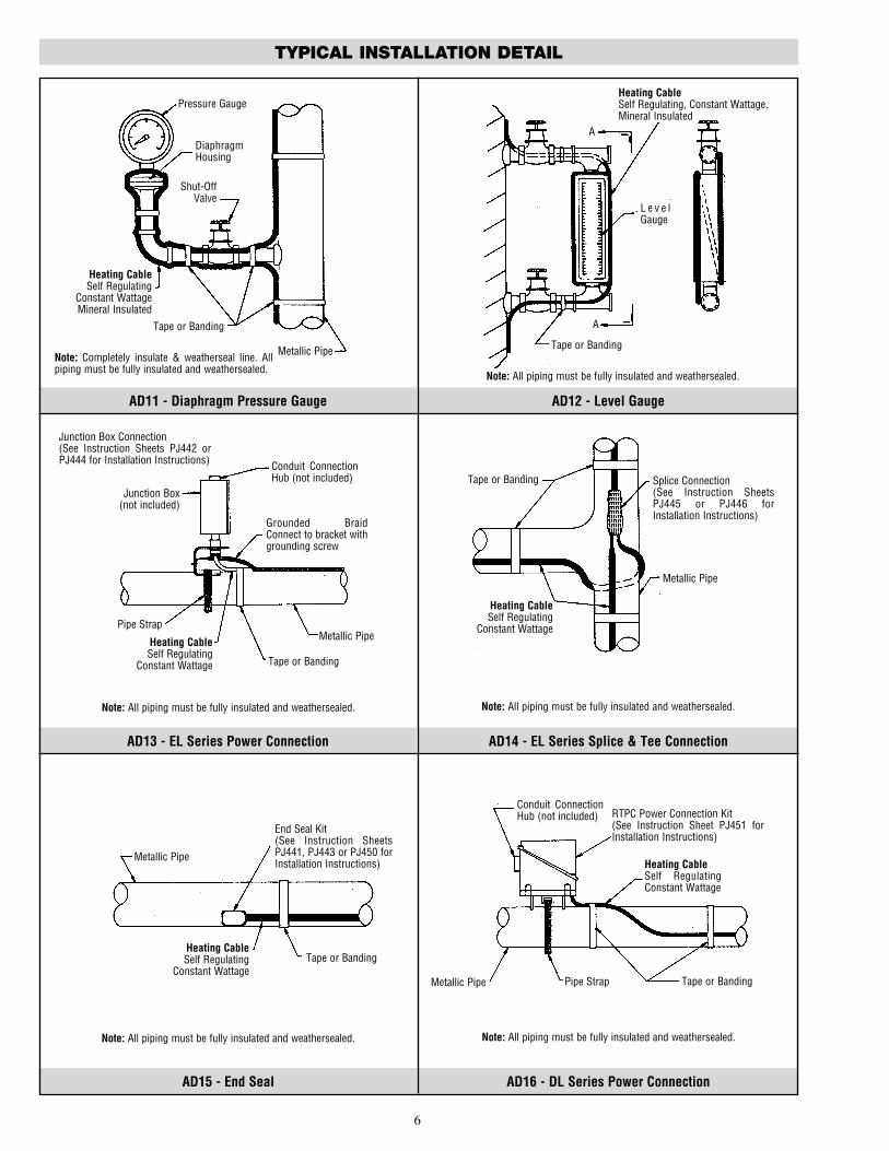
AD15 - End Seal AD16 - DL Series Power Connection
AD13 - EL Series Power Connection AD14 - EL Series Splice & Tee Connection
AD11 - Diaphragm Pressure Gauge AD12 - Level Gauge
TYPICAL INSTALLATION DETAIL
6
Metallic Pipe
Tape or Banding
Heating CableSelf Regulating
Constant WattageMineral Insulated
Note: Completely insulate & weatherseal line. Allpiping must be fully insulated and weathersealed.
Tape or Banding
Heating CableSelf Regulating, Constant Wattage,Mineral Insulated
Note: All piping must be fully insulated and weathersealed.
A
L e v e lGauge
Pressure Gauge
Shut-OffValve
DiaphragmHousing
A
Metallic Pipe
Tape or Banding
Heating CableSelf Regulating
Constant Wattage
Note: All piping must be fully insulated and weathersealed.
Grounded BraidConnect to bracket withgrounding screw
Junction Box(not included)
Conduit ConnectionHub (not included)
Pipe Strap
Junction Box Connection(See Instruction Sheets PJ442 orPJ444 for Installation Instructions)
Splice Connection(See Instruction SheetsPJ445 or PJ446 forInstallation Instructions)
Tape or Banding
Heating CableSelf Regulating
Constant Wattage
Note: All piping must be fully insulated and weathersealed.
Metallic Pipe
Metallic Pipe
Tape or BandingHeating CableSelf Regulating
Constant Wattage
Note: All piping must be fully insulated and weathersealed.
End Seal Kit(See Instruction SheetsPJ441, PJ443 or PJ450 forInstallation Instructions)
Metallic Pipe Tape or Banding
Heating CableSelf RegulatingConstant Wattage
Note: All piping must be fully insulated and weathersealed.
Conduit ConnectionHub (not included)
Pipe Strap
RTPC Power Connection Kit(See Instruction Sheet PJ451 forInstallation Instructions)

AD17 - DL Series Splice & Tee Connection AD18 - Sensor Placement
TYPICAL INSTALLATION DETAIL
7
Metallic Pipe
Tape or Banding to holdheating cable
Heating CableSelf RegulatingConstant WattageMineral Insulated
3 FootMinimum
Thermal Insulating
WeatherproofJacket
90˚
Note:1. For multiple heaters placecontrol sensor 90˚ from nearestheater or centered betweenequally spaced heaters.2. Place high-limit sensorapproximately 15” from heaterand mount in the same manneras shown below.
Tape Bulbtight against pipeNearest pipe support
or other heat sink
Section A-AControl Sensor
Metallic Pipe
Tape or Banding
Heating CableSelf Regulating
Constant Wattage
Note: All piping must be fully insulated and weathersealed.
Pipe Strap
RTST Splice and Tee Kit(See Instruction Sheet PJ452for Installation Instructions)
AD15 - End Seal AD16 - DL Series Power Connection
AD13 - EL Series Power Connection AD14 - EL Series Splice & Tee Connection
Metallic Pipe
Tape or Banding
Heating CableSelf Regulating
Constant Wattage
Note: All piping must be fully insulated and weathersealed.
Grounded BraidConnect to bracket withgrounding screw
Junction Box(not included)
Conduit ConnectionHub (not included)
Pipe Strap
Junction Box Connection(See Instruction Sheets PJ442 orPJ444 for Installation Instructions)
Splice Connection(See Instruction SheetsPJ445 or PJ446 forInstallation Instructions)
Tape or Banding
Heating CableSelf Regulating
Constant Wattage
Note: All piping must be fully insulated and weathersealed.
Metallic Pipe
Metallic Pipe
Tape or BandingHeating CableSelf Regulating
Constant Wattage
Note: All piping must be fully insulated and weathersealed.
End Seal Kit(See Instruction SheetsPJ441, PJ443 or PJ450 forInstallation Instructions)
Metallic Pipe Tape or Banding
Heating CableSelf RegulatingConstant Wattage
Note: All piping must be fully insulated and weathersealed.
Conduit ConnectionHub (not included)
Pipe Strap
RTPC Power Connection Kit(See Instruction Sheet PJ451 forInstallation Instructions)

8
III. Mineral Insulated
End Cap
End CapCold Lead
Heat Resistance WireHeat Resistance Wire
Thermostat
ThermostatThermostat
L1
L1
L2
L2
Power Supply
Contactor
L1L2 Power
Supply
ControlCircuitOR
Typical Wiring Diagrams
I. Self-Regulating
End Cap
Buss Wire
Heat Resistance Wire
Thermostat
L1
L2Power Supply
End Cap Buss Wire
Heat Resistance Wire
Thermostat
Contactor
L1L2 Power
Supply
ControlCircuit
II. Constant Wattage
End Cap
Buss Wire
Heat Generating Matrix
Thermostat
L1
L2Power Supply
End Cap Buss Wire
Heat Generating Matrix
Thermostat
Contactor
L1L2 Power
Supply
ControlCircuit
Typical Wiring Diagrams Typical Wiring Diagrams
WIRING
ELECTRIC SHOCK HAZARD. Disconnect all powerbefore installing or servicing heating cable. Failureto do so could result in personal injury or propertydamage. Heater must be installed by a qualifiedperson in accordance with the National ElectricalCode, NFPA 70.
ELECTRIC SHOCK HAZARD. Any installation involv-ing electric heating cables must be performed by aqualified person and must be effectively groundedin accordance with the National Electrical Code toeliminate shock hazard.
ACCESSORIES:1. Selection of Installation Accessories should be in accordance
with Chromalox bulletin PJ309 and PJ304.2. Only use Chromalox installation kits and use them only for the
operations for which they are designed.3. The instructions included in the Chromalox installation acces-
sories must be followed in order for the third party approvals(UL, FM, CSA, etc.) to apply.
4. Junction boxes must be in accordance with the requirements ofthe area classification.
5. All outdoor junction boxes must be located above grade level.Covers should be kept on the boxes at all time when not beingworked in.
6. All terminations must be protected from the weather and fromphysical damage by locating them either under the weatherproofinsulation or inside an appropriate junction box.
7. All equipment must be properly grounded.8. Install installation accessories according to the instructions
included in the kits and per installation details AD13 throughAD17.
To prevent equipment damage, Circuits fed fromoverhead lines should be protected by secondarylighting arrestors.CONTROLS:1. All heating circuits should have temperature controls. Temper-
ature control of the pipeline can be obtained through variousChromalox temperature controls. Refer to Chromalox bulletinsPJ304 and PJ310 for recommendations.
2. Contactors must be used when load currents exceed the rating ofthe thermostat contacts. Equipment protection ground fault (30mA EPD) thermal breakers are recommended with type SRL.
3. The temperature control should be mounted in a location whereit will not be subjected to excessive shock or vibration.
4. Line sensing temperature sensors should be mounted in accor-dance with Installation Detail AD18 (see Detail on previouspage).
5. Ambient sensing temperature sensors should be located at apoint where the lowest ambient temperature is expected.
To prevent equipment damage, handle and securetemperature sensors, especially thermostat bulbsand capillaries with care to avoid distortion orcrimping which might impair control accuracy.
6. Exposed thermostat capillaries should have mechanical protec-tion.

9
INSTALLATION TESTING
THERMAL INSULATION
COMMISSION TESTING
When the heater cable and connections for a circuit have beencompleted, immediately perform the following checks.
1. Visually inspect the heater cable and temperature controls forsigns of mechanical damage. If damage is seen, either replace thecomplete heater cable, or cut out the damaged section andreplace using the proper splice connection for the area and cableyou are using.
2. Inspect all connections to be sure they are correctly assembled.Be sure each heater cable entry to a connection has a grommetand the compression plates and caps are properly tightened.
3. Inspect the insulation resistance of the circuit using a 500VDCmegger. Always perform this test at the power connection. Anycable with an insulation resistance of less than 10 megohmsshould be removed and discarded.
4. Check voltage at end of circuit and record in log.
An installed heating circuit should be thermally insulated imme-diately to provide protection from damage from ongoing work.Things to remember about insulating:
1. Insulate the equipment being heat traced as soon as possible afterthe heating cable is installed. This will protect the cable frompossible physical damage.
2. The type and thickness of thermal insulation specified on thedesign drawing must be used. If you use another type or thick-ness, the heater cable type or amount may have to be changed.
3. Never install wet insulation. Both the piping and the insulationmust be dry when thermally insulating a circuit. Wet insulationmay cause start-up or operational problems.
4. Properly weatherproof the thermal insulation. All places wherevalve stems, conduits, pipe supports, connection housing, ther-mal capillary tubes, etc. extend outside the insulation jacketingmust be sealed with a suitable compound to keep water out.
5. Insulate valves fully up to, and including, the packing gland.6. Heat trace and fully insulate the face of all non-diaphragm pres-
sure instruments.
7. Insulation must be covered by a weatherproof barrier, such as analuminum jacket.
8. If you are using metal jacketing and sheet metal screws, be surethe screws are not long enough to penetrate the thermal insula-tion and damage the heater cable.
9. Again, perform the megger test on the circuit immediately afterthe thermal insulation is installed to detect if any mechanicaldamage may have occurred.
10. When the insulation and the weatherproofing is complete, attach“Electric Traced” labels on the outside of the insulation. Theseshould be installed where they are visible from normal opera-tions, usually on alternating sides about every 10 feet. It is alsouseful to mark the location of any connections buried under theinsulation.
Additional requirements for rigid thermal insulations:1. In the standard single heater cable installation, rigid insulations
do not need to be oversized. However, they should be carved sothere is no gap in the insulation.
2. In case of redundant or multiple heater cables, rigid insulationswhich are .500 inches oversized should be used.
1. Again, visually inspect the piping, insulation and connections forthe heater cable to make sure no physical damage has occurredif some time period has elapsed since the installation and start-up.
2. Megger the system again to determine if damage not readily vis-ible has occurred.
3. Turn all branch circuit breakers to the OFF position.
For systems controlled by ambient-sensing thermostats:1. If the actual ambient temperature is higher than the desired ther-
mostat setting, turn the thermostat setting up high enough to turnthe system ON or (some models) turn the selector switch to theON position.
2. Turn the main circuit breaker ON.3. Turn the branch breakers ON one-by-one until all are on.4. Allow system to run at least four hours in order to let all pipes
reach steady-state.5. Measure the amperage draw, ambient temperature and pipe tem-
perature for each circuit and record in the installation log. Thisinformation may be needed for future maintenance and trou-bleshooting.
6. When the system is completely checked out, reset the thermostatto the proper temperature.
For systems controlled by line-sensing thermostats:1. Set the thermostat to the desired control temperature.2. Turn the main circuit breaker ON.3. Turn ON the branch circuit breakers controlled by the thermo-
stat.4. Allow the pipe temperatures to be raised to the control point.
This may take up to four hours for most circuits (large full pipesmay take longer).
5. Measure the amperage draw. ambient temperature, and pipe tem-perature for each circuit and record in the installation log. Thisinformation may be needed for future maintenance and trou-bleshooting.
For redundant systems:Follow the procedure above for the type of control system you
have, but commission the systems one at a time. Start up the pri-mary system, qualify it and shut it down. Then start up the back-up system, qualify it and shut it down.

10
50°F Start-Up (Ft.) 0°F Start-Up (Ft.) -20°F Start-Up (Ft.)
Cable Rating 10A 15A 20A 25A 30A 40A 10A 15A 20A 25A 30A 40A 10A 15A 20A 25A 30A 40ASRL / HSRL3-1C 205 305 360 NR NR NR 135 200 270 330 360 NR 120 185 245 300 360 NRSRL / HSRL3-2C 400 600 660 NR NR NR 275 415 555 660 NR NR 245 370 495 600 660 NRSRL / HSRL5-1C 125 185 250 270 NR NR 90 135 180 225 270 NR 80 120 160 205 245 270SRL / HSRL5-2C 250 375 505 540 NR NR 180 270 360 450 540 NR 160 245 325 405 490 540SRL / HSRL8-1C 100 150 200 215 NR NR 70 110 145 180 215 NR 65 100 130 165 200 210SRL / HSRL8-2C 185 285 375 420 NR NR 135 200 265 335 395 420 120 175 235 300 350 420SRL / HSRL10-1C 60 95 130 160 180 NR 50 80 105 130 155 180 45 70 95 120 140 180SRL / HSRL10-2C 100 160 210 260 315 360 80 125 170 210 255 340 75 120 160 195 240 320
CABLE TYPE MAX. MAINTAIN (POWER ON) MAX EXPOSURE (POWER OFF)SRL / HSRL 150˚F 185˚F
SRM/E / HSRM 302˚F 420˚FCWM See table below See table belowSRF 150˚F 185˚F
Table 1 – Maximum Temperatures
Temperatures (°F)
Output(W/Ft.) 3 4 6 6.7 8 9 10.1 10.6 12
w/o AT-1 Tape 340 325 293 282 262 246 229 222 200
w/ AT-1 Tape 350 344 332 328 320 314 307 304 296
Table 2 – Maximum Maintenance Temperatures
Table 3 – Maximum Circuit LengthsSRL / HSRL Circuit Breaker Selection (Max. Circuit Lengths in Ft.)
SPECIFICATIONS
Circuit Load Max. Circuit LengthModel (Amps/Ft.) (Ft.)CWM 4-1CT 0.033 350CWM 8-1CT 0.067 240CWM 12-1CT 0.100 200CWM 4-2CT 0.017 700CWM 8-2CT 0.033 480CWM 12-2CT 0.050 400CWM 12-4CT 0.025 780
50°F Start-Up (Ft.) 0°F Start-Up (Ft.) -20°F Start-Up (Ft.)
Cable Rating 15A 20A 30A 40A 50A 15A 20A 30A 40A 50A 15A 20A 30A 40A 50ASRM/E / HSRM 3-1 285 385 NR NR NR 275 375 385 NR NR 265 365 385 NR NRSRM/E / HSRM 3-2 575 770 780 NR NR 540 750 780 NR NR 525 740 780 NR NRSRM/E / HSRM 5-1 180 240 360 375 NR 165 220 330 375 NR 155 210 310 375 NRSRM/E / HSRM 5-2 360 480 720 750 NR 325 430 645 750 NR 310 415 620 750 NRSRM/E / HSRM 8-1 145 190 285 325 NR 135 175 265 325 NR 130 165 250 325 NRSRM/E / HSRM 8-2 285 380 575 650 NR 255 345 520 650 NR 245 335 490 650 NRSRM/E / HSRM 10-1 95 125 190 250 NR 90 110 175 250 NR 85 100 170 245 250SRM/E / HSRM 10-2 190 255 385 490 NR 165 225 345 490 NR 155 215 330 470 490SRM/E / HSRM 15-1 70 95 145 190 210 65 85 125 165 210 60 80 120 150 210SRM/E / HSRM 15-2 145 190 290 385 420 120 175 270 360 420 115 165 260 340 420SRM/E / HSRM 20-1 60 75 115 155 160 50 65 105 140 160 45 65 100 135 160SRM/E / HSRM 20-2 115 155 230 305 350 100 135 200 270 350 90 130 195 255 335
NR = Not Required. Maximum circuit length has been reached in a smaller breaker size.Note — Thermal magnetic circuit breakers are recommended since magnetic circuit breakers could "nuisance trip" at low temperature.
SRM/E / HSRM Circuit Breaker Selection (Max. Circuit Lengths in Ft.)
CWM Specifications SRF Circuit Breaker Selection (Max. Circuit Lengths in Ft.)40°F Start-Up (Ft.) 0°F Start-Up (Ft.)
Cable Rating 20A 30A 40A 20A 30A 40ASRF 3-1C 350 360 NR 270 360 NRSRF 3-2C 660 NR NR 555 660 NRSRF 5-1C 230 270 NR 180 270 NRSRF 5-2C 450 540 NR 360 540 NRSRF 8-1C 180 215 NR 145 215 NRSRF 8-2C 330 420 420 265 395 420

11
INSTALLATION AND MAINTENANCE LOG
Reference Information
Circuit NumberCircuit Breaker NumberDrawing NumberCircuit Length
Heat Tracing Visual Checks
No Signs of Moisture, Corrosion or DamageInitialDate
Proper Electrical ConnectionInitialDate
Proper Grounding of the BraidInitialDate
Heat Tracing Electrical Checks
Megger Test (500 VDC) Meg Ohms(Bypass Controls) Date
Amperage Draw TestAmperage
Compare to design Amperage Draw Amb. Temp.Date
Voltage at end of Circuit*Voltage
DateAccessories/Control Checks
Temperature Control Properly SetSet Point
Date
Sensors Protected and UndamagedInitialDate
All Enclosures and Kits Closed and SealedInitialDate
Thermal Insulation Checks
Location of Kits Visible on InitialOutside of Insulation Date
Insulation is Complete, Dry and WeatherproofInitialDate
* This test must be performed at installation or at any time the cable is cut or damaged in any way.
MAINTENANCE
Recommended maintenance for Chromalox heat tracing systemsconsists of performing the steps involved in the commission testingon a regular basis. For those systems controlled by line sensing ther-mostats, Chromalox recommends checking the system at least twiceper year. Systems controlled by an ambient-sensing thermostatshould be checked when the season requiring their use is approach-ing.
Repair or replace all damaged heater cable, connections, thermalinsulation and weatherproofing using only Chromalox connectionsand methods before testing the system.
Record all repairs made and measurements taken in the installa-tion and maintenance log.

TA - Y6 - EFLitho in U.S.A.
103 GAMMA DRIVE, PITTSBURGH, PA 15238Phone: 800-443-2640 www.chromalox.com
Chromalox warrants only that the Products and parts manufactured by Chromalox, when shipped,and the work performed by Chromalox when performed, will meet all applicable specification andother specific product and work requirements (including those of performance), if any, and will befree from defects in material and workmanship under normal conditions of use. All claims for defec-tive or nonconforming (both hereinafter called defective) Products, parts or work under this war-ranty must be made in writing immediately upon discovery, and in any event, within one (1) yearfrom delivery, provided, however all claims for defective Products and parts must be made in writ-ing no later than eighteen (18) months after shipment by Chromalox. Defective and nonconformingitems must be held for Chromalox's inspections and returned to the original f.o.b. point uponrequest. THE FOREGOING IS EXPRESSLY IN LIEU OF ALL OTHER WARRANTIES WHATSOEVER,EXPRESS, IMPLIED AND STATUTORY, INCLUDING, WITHOUT LIMITATION, THE IMPLIED WAR-RANTIES OF MERCHANTABILITY AND FITNESS FOR A PARTICULAR PURPOSE.
Notwithstanding the provisions of this WARRANTY AND LIMITATION Clause, it is specificallyunderstood that Products and parts not manufactured and work not performed by Chromalox arewarranted only to the extent and in the manner that the same are warranted to Chromalox byChromalox's vendors, and then only to the extent that Chromalox is reasonably able to enforce suchwarranty, it being understood Chromalox shall have no obligation to initiate litigation unless Buyerundertakes to pay all cost and expenses therefor, including but not limited to attorney's fees, and
indemnifies Chromalox against any liability to Chromalox's vendors arising out of such litigation.Upon Buyer's submission of a claim as provided above and its substantiation, Chromalox shall at
its option either (i) repair or replace its Products, parts or work at the original f.o.b. point of deliv-ery or (ii) refund an equitable portion of the purchase price.
THE FOREGOING IS CHROMALOX'S ONLY OBLIGATION AND BUYER'S EXCLUSIVE REMEDYFOR BREACH OF WARRANTY, AND IS BUYER'S EXCLUSIVE REMEDY AGAINST CHROMALOX FORALL CLAIMS ARISING HEREUNDER OR RELATING HERETO WHETHER SUCH CLAIMS ARE BASEDON BREACH OF CONTRACT, TORT (INCLUDING NEGLIGENCE AND STRICT LIABILITY) OR OTHERTHEORIES, BUYER'S FAILURE TO SUBMIT A CLAIM AS PROVIDED ABOVE SHALL SPECIFICALLYWAIVE ALL CLAIMS FOR DAMAGES OR OTHER RELIEF, INCLUDING BUT NOT LIMITED TOCLAIMS BASED ON LATENT DEFECTS. IN NO EVENT SHALL BUYER BE ENTITLED TO INCIDENTALOR CONSEQUENTIAL DAMAGES AND BUYER SHALL HOLD CHROMALOX HARMLESS THERE-FROM. ANY ACTION BY BUYER ARISING HEREUNDER OR RELATING HERETO, WHETHER BASEDON BREACH OF CONTRACT, TORT (INCLUDING NEGLIGENCE AND STRICT LIABILITY) OR OTHERTHEORIES, MUST BE COMMENCED WITHIN ONE (1) YEAR AFTER THE DATE OF SHIPMENT OR ITSHALL BE BARRED.
W2008M
WARRANTY AND LIMITATION OF REMEDY AND LIABILITY