Thesis Description of the Operation of the Transfer Current Chopper
Upload
vishalgohel12195Category
view
169download
5
chopper Operation
Overview
IntroductionPrinciple of chopper OperationControl strategiesStep up ChopperApplications of Choppers
Introduction
•Chopper is a static device.•A variable dc voltage is obtained from a constant dc voltage source.•Also known as dc-to-dc converter.•Widely used for motor control.•Also used in regenerative braking.• Thyristor converter offers greater efficiency, faster response, lower maintenance, smaller size and smooth control.
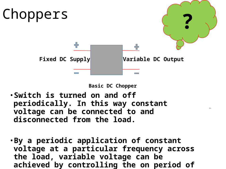
• Switch is turned on and off periodically. In this way constant voltage can be connected to and disconnected from the load.
• By a periodic application of constant voltage at a particular frequency across the load, variable voltage can be achieved by controlling the on period of the switch.
4
Basic DC Chopper
Choppers
Fixed DC Supply Variable DC Output
?
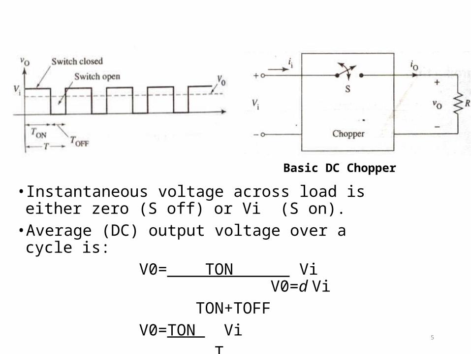
• Instantaneous voltage across load is either zero (S off) or Vi (S on).•Average (DC) output voltage over a cycle is: V0= TON Vi V0=d Vi TON+TOFF V0=TON Vi T 5
Basic DC Chopper
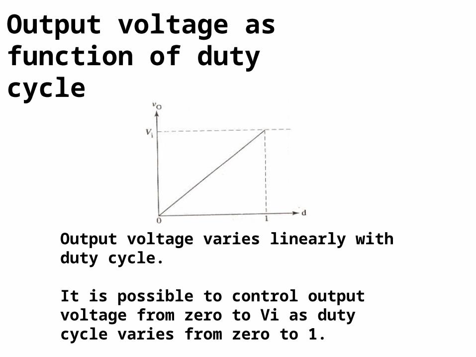
Output voltage as function of duty cycle
Output voltage varies linearly with duty cycle.
It is possible to control output voltage from zero to Vi as duty cycle varies from zero to 1.
Methods Of Control
•The output dc voltage can be varied by the following methods.•Pulse width modulation control or constant frequency operation.•Variable frequency control.
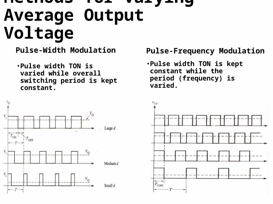
Methods for varying Average Output Voltage
Pulse-Width Modulation
• Pulse width TON is varied while overall switching period is kept constant.
Pulse-Frequency Modulation
• Pulse width TON is kept constant while the period (frequency) is varied.
Choppers are of Two Types
Step-down choppers.Step-up choppers.
In step down chopper output voltage is less than input voltage.
In step up chopper output voltage is more than input voltage.
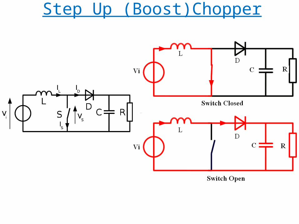
Step Up (Boost)Chopper
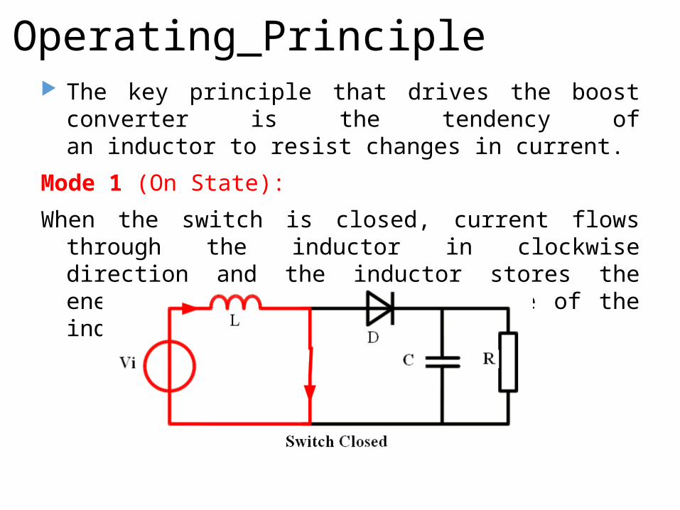
Operating Principle The key principle that drives the boost converter is the
tendency of an inductor to resist changes in current.
Mode 1 (On State):
When the switch is closed, current flows through the inductor in clockwise direction and the inductor stores the energy. Polarity of the left side of the inductor is positive.
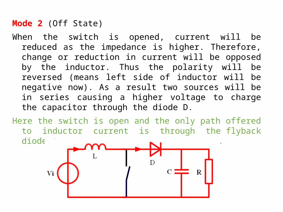
Mode 2 (Off State)
When the switch is opened, current will be reduced as the impedance is higher. Therefore, change or reduction in current will be opposed by the inductor. Thus the polarity will be reversed (means left side of inductor will be negative now). As a result two sources will be in series causing a higher voltage to charge the capacitor through the diode D.
Here the switch is open and the only path offered to inductor current is through the flyback diode D, the capacitor C and the load R.
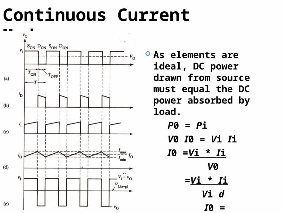
Continuous Current Mode
As elements are ideal, DC power drawn from source must equal the DC power absorbed by load.
P0 = PiV0 I0 = Vi IiI0 =Vi * Ii V0 =Vi * Ii Vi d
I0 = Ii_ d
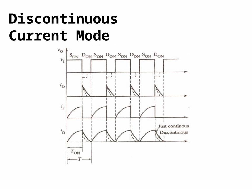
Discontinuous Current Mode
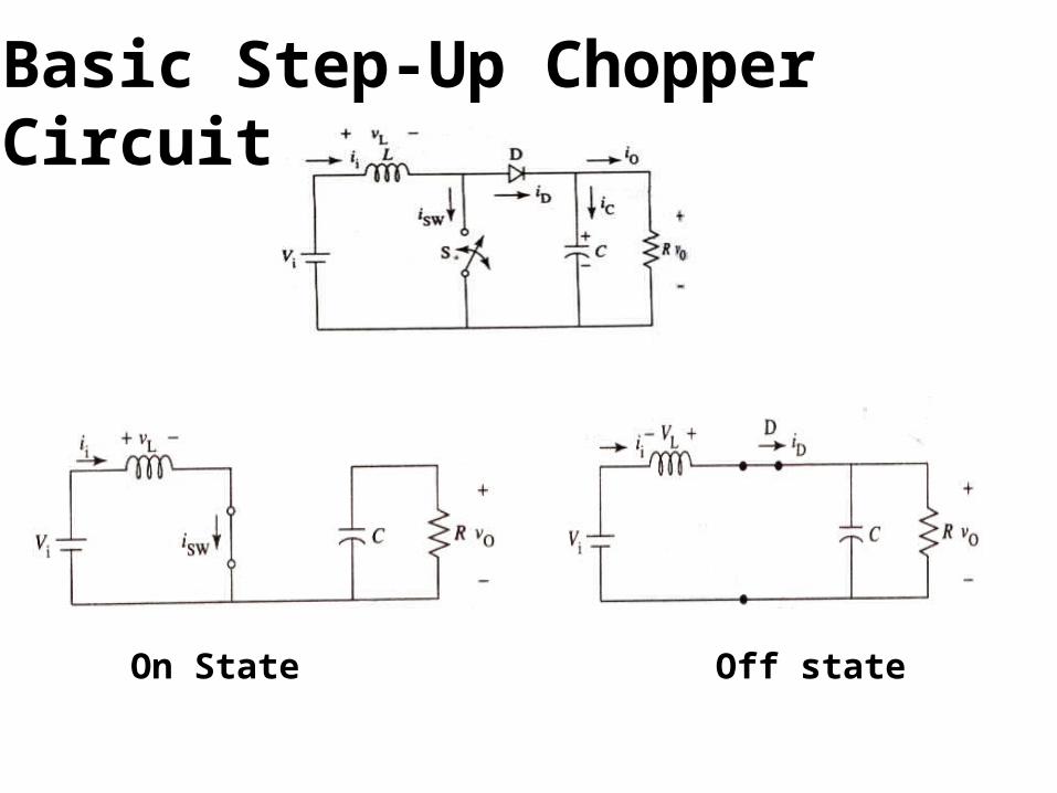
Basic Step-Up Chopper Circuit
On State Off state
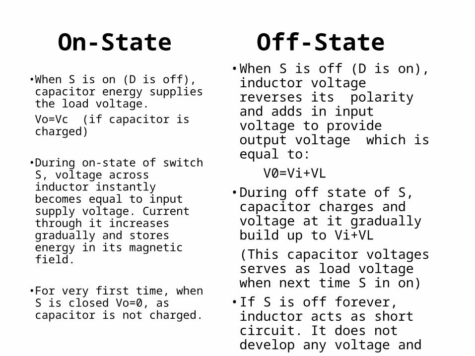
On-State• When S is on (D is off),
capacitor energy supplies the load voltage.Vo=Vc (if capacitor is charged)
• During on-state of switch S, voltage across inductor instantly becomes equal to input supply voltage. Current through it increases gradually and stores energy in its magnetic field.
• For very first time, when S is closed Vo=0, as capacitor is not charged.
Off-State• When S is off (D is on), inductor
voltage reverses its polarity and adds in input voltage to provide output voltage which is equal to:
V0=Vi+VL• During off state of S, capacitor
charges and voltage at it gradually build up to Vi+VL(This capacitor voltages serves as load voltage when next time S in on)• If S is off forever, inductor acts as
short circuit. It does not develop any voltage and
Vo= Vi
Application Chopper are used for DC motor control( battery - supplied
vehicles), Solar and Wind energy conservation It’s also used in electric cars. Airplane and spaceships ,where onboard-regulated DC
power supplies are required. Chopper circuits are used as power supplies in computers,
commercial electronics, electronics instruments.