CHLORITE POLYTYPISM: IV. REGULAR TWO-LAYER STRUCTURES ... · THE AMERICAN MINERALOGIST. VOL. 52....
18
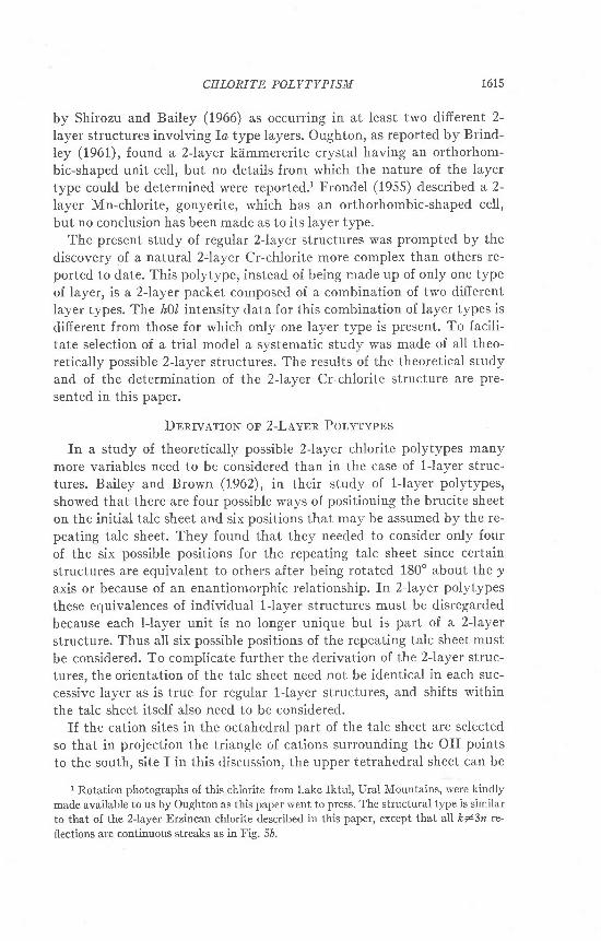
THE AMERICAN MINERALOGIST. VOL. 52. NOVEMBER DECEMBER. 1967 CHLORITE POLYTYPISM: IV. REGULAR TWO-LAYER STRUCTURES Juorrn S. LrsrBn AND S. W. Barr-rv, Department of Geology, Uni- aersity of Wisconsin, Madi,son, Wi,sconsin. Ansrnacr Theoretical 2Jayer chlorite polytypes may be classified according to 64 unique [010] projection groups. These groups contain a total of 1134 unique individual 2-layer poly- types, of which 1009 have a monoclinic-shaped unit cell and 125 have an orthorhombic- shaped unit cell. Natural 2Jayer specimens are rare; representatives of only three of the [010] projection groups have been found to date. Most of these 2Jayer structures belong to two of the projection groups and are composed of only a single structural layer type, either Io or IIb. The third natural group is difierent in that the structures contain 2Jayer packets made up of two different layer types. Several crystals of purple Cr-chlorite from Erzincan, Turkey, which belong to this third group, have been studied in detail. The apparent space group of one of the 2-layer Erzincan crystals is C1 with a:5.335, b:9.240, c:28.735 A, and o: B: r:90o. The ideal model on which the structure is based has a c-glide plane perpendicular to the short axis. This symmetry plane is destroyed by an ordered distribution of the Cr atoms within the brucite sheet over positions not related by a c-glide. The 2Jayer repeat is due to a regular alternation of octahedral cations between I and II sites in both the talc and brucite sheets of the two iayers. The talc network is dis- torted by 60 planar rotations of the tetrahedra. The crystal is twinned and is made up of six roughly triangular sectors. The slx sectors comprise two interpenetrating sets of three members each, believed to be related by a rotation of 180o about the [010] axis. Composition planes are (100), (130), and (130). A1l crystals containing 2-layer packets are twinned and are elongate along Z The twinning has prevented complete refinement of the structure. INrnopucrrow In part I of this study of chlorite polytypism Bailey and Brown (1962) showed that four different types of chlorite layers,designated Ia,Ib,IIa, and 116,are theoretically possible. Layers of the same type can be super- imposed to form twelve unique 1-layer polytypes having a regular stacking sequence and six structures having a semirandom stacking sequence. Of the four basic layer types, all except the IIo type have been recognized in natural specimens. In addition to l-layer and semirandom structures, several regular multipleJayer polytypes are known to exist. Brindley et al. (1950) rec- ognized some multiple-layer chlorite polytypes, including a 2-layer variety having a monoclinic-shapedcell. All of the layers in these mul- tiple-layer structures are of the same strucutral type, 116.Two different 2-layer monoclinic polytypes of cookeite, a Li-Al dioctahedral chlorite, also are made up of a single layer type, in this case the Ia layer (Lister, 1966). Drits (1966) has reported a 2-layer Al-Mg dioctahedral chlorite containing IID type layers. Vermiculite, which is very similar to chlorite in structure, has been described by Mathieson and Walker (1954) and t6t4
Transcript of CHLORITE POLYTYPISM: IV. REGULAR TWO-LAYER STRUCTURES ... · THE AMERICAN MINERALOGIST. VOL. 52....
THE AMERICAN MINERALOGIST. VOL. 52. NOVEMBER DECEMBER. 1967
CHLORITE POLYTYPISM: IV. REGULAR TWO-LAYERSTRUCTURES
Juorrn S. LrsrBn AND S. W. Barr-rv, Department of Geology, Uni-aersity of Wisconsin, Madi,son, Wi,sconsin.
Ansrnacr
Theoretical 2Jayer chlorite polytypes may be classified according to 64 unique [010]projection groups. These groups contain a total of 1134 unique individual 2-layer poly-types, of which 1009 have a monoclinic-shaped unit cell and 125 have an orthorhombic-shaped unit cell. Natural 2Jayer specimens are rare; representatives of only three of the
[010] projection groups have been found to date. Most of these 2Jayer structures belongto two of the projection groups and are composed of only a single structural layer type,either Io or IIb. The third natural group is difierent in that the structures contain 2Jayerpackets made up of two different layer types. Several crystals of purple Cr-chlorite fromErzincan, Turkey, which belong to this third group, have been studied in detail.
The apparent space group of one of the 2-layer Erzincan crystals is C1 with a:5.335,b:9.240, c:28.735 A, and o: B: r:90o. The ideal model on which the structure is basedhas a c-glide plane perpendicular to the short axis. This symmetry plane is destroyed by anordered distribution of the Cr atoms within the brucite sheet over positions not related bya c-glide. The 2Jayer repeat is due to a regular alternation of octahedral cations between Iand II sites in both the talc and brucite sheets of the two iayers. The talc network is dis-torted by 60 planar rotations of the tetrahedra. The crystal is twinned and is made up ofsix roughly triangular sectors. The slx sectors comprise two interpenetrating sets of threemembers each, believed to be related by a rotation of 180o about the [010] axis. Compositionplanes are (100), (130), and (130). A1l crystals containing 2-layer packets are twinned andare elongate along Z The twinning has prevented complete refinement of the structure.
INrnopucrrow
In part I of this study of chlorite polytypism Bailey and Brown (1962)showed that four different types of chlorite layers, designated Ia,Ib,IIa,and 116, are theoretically possible. Layers of the same type can be super-imposed to form twelve unique 1-layer polytypes having a regularstacking sequence and six structures having a semirandom stackingsequence. Of the four basic layer types, all except the IIo type have beenrecognized in natural specimens.
In addition to l-layer and semirandom structures, several regularmultipleJayer polytypes are known to exist. Brindley et al. (1950) rec-ognized some multiple-layer chlorite polytypes, including a 2-layervariety having a monoclinic-shaped cell. All of the layers in these mul-tiple-layer structures are of the same strucutral type, 116. Two different2-layer monoclinic polytypes of cookeite, a Li-Al dioctahedral chlorite,also are made up of a single layer type, in this case the Ia layer (Lister,1966). Drits (1966) has reported a 2-layer Al-Mg dioctahedral chloritecontaining IID type layers. Vermiculite, which is very similar to chloritein structure, has been described by Mathieson and Walker (1954) and
t6t4
CHI,ORITE POLYTYPISM 1615
by Shirozu and Bailey (1966) as occurring in at least two different 2-layer structures involving Ia type layers. Oughton, as reported by Brind-ley (1961), found a 2-layer kemmererite crystal having an orthorhom-bic-shaped unit cell, but no details from which the nature of the layertype could be determined were reported.l Frondel (1955) described a 2-layer Mn-chlorite, gonyerite, which has an orthorhombic-shaped cell,but no conclusion has been made as to its layer type.
The present study of regular 2-layer structures was prompted by thediscovery of a natural 2:Iayer Cr-chlorite more complex than others re-ported to date. This polytype, instead of being made up of only one typeof layer, is a 2-layer packet composed of a combination of two differentlayer types. The h\l intensity data for this combination of layer types isdifferent from those for which only one layer type is present. To facili-tate selection of a trial model a systematic study was made of all theo-retically possible 2-layer structures. The results of the theoretical studyand of the determination of the 2-layer Cr-chlorite structure are pre-sented in this paper.
Dnnrvarrorq oF 2-LAYER Porvrvpps
In a study of theoretically possible 2-layer chlorite polytypes manymore variables need to be considered than in the case of l-layer struc-tures. Bailey and Brown (1962), in their study of l-layer polytypes,showed that there are four possible ways of positioning the brucite sheeton the initial talc sheet and six positions that may be assumed by the re-peating talc sheet. They found that they needed to consider only fourof the six possible positions for the repeating talc sheet since certainstructures are equivalent to others after being rotated 180" about the Iaxis or because of an enantiomorphic relationship. In Z-layer polytypes
these equivalences of individual 1-layer structures must be disregardedbecause each l-layer unit is no longer unique but is part of a. 2-layerstructure. Thus all six possible positions of the repeating talc sheet must
be considered. To complicate further the derivation of the 2-layer struc-tures, the orientation of the talc sheet need not be identical in each suc-
cessive layer as is true for regular l-layer structures, and shifts withinthe talc sheet itself also need to be considered.
If the cation sites in the octahedral part of the talc sheet are selectedso that in projection the triangle of cations surrounding the OH points
to the south, site I in this discussion, the upper tetrahedral sheet can be
I Rotation photographs of this chlorite from Lake Iktul, Ural Mountains, were kindly
made available to us by Oughton as this paper went to press. The structural type is similar
to that of the 2Jayer Erzincan chlorite described in this paper, except that all kl3n re'
flections are continuous streaks as in Fis. 5b.

1616 TUDITH S. LISTER AND S. W. BAILEY
displaced relative to the lower tetrahedral sheet only along the negative'r1, n2, or ra &X€s if close packing of the octahedral anions is to be pre-served. However if the alternate site for the octahedral cations is chosen,site II in this paper, so that in projection the triangle of cations aroundthe OH points north, the upper tetrahedral sheet may only be shiftedalong the positive n1, lr,2, ot 13 o.X€s (Fig. 1) . These last three arrangementscorrespond to the L, N, amd M structures, respectively, of Brindley elal. (1950). In referring to the talc sheets in the following discussion, thosebuilt up with site f occupied will be designated *1, ft2, or 13, depending onwhether the shift has been along a negative !c1, )e, or 13 axis respectively.
+ x r
b)Frc. 1. Diagram of the octahedral portion of the talc sheet. The lower O-OH anion plane
is drawn with dashed lines. Occupation of cation site I requires a shift of the upper anionplane along the -* axis and occupation of cation site II requires a shift of the upper anionplane along the fr axis to maintain close packing of octahedral anions.
Those built up with site II occupied will be called o1, 12, or tca, correspond-ing to a shift along the positive $1, ec2, ot 13 axis respectively. In thismanner the terminology will have meaning in reference to a fixed crystal-lographic orientation. It should be noted that the crystallographic axesof the resultant structure may not coincide with the fixed axes used inthe theoretical polytype derivation.
To describe completely a 2-layer chlorite polytype six terms need to beused. Each chlorite layer is described separately according to the ter-minology of Bailey and Brown (1962) and one additional term is added todescribe the variables within the talc sheet of each layer. For an exampleof how the description of a polytype is set up we consider the structureof sr-Io-S : rz-IIb-3. The first term is the symbol representing the shiftwithin the init ial talc sheet, as shown in Fig. 1o. This term automatically
o)
qO
t i

CHI,ORITE POLYTYPISM 1617
indicates the choice of octahedral cation site. Possibilities are 81, 82, 83,ot rc1, t2, 13, cation sites I and II respectively. The symbol describing thetalc sheet variable is followed by the symbol for the type of brucite sheet.Possibil i t ies are Ia,Ib,IIa, or 116. Finally, the position of the talc sheetof the second layer relative to the brucite sheet of the first layer is rep-resented by a number, I, 2, 3,4, 5, or 6. To avoid any possible confusionin applying the definitions of these six positions to 2-layer structures, itshould be pointed out that the six positions may not always be distrib-uted about a N-S mirror plane in the talc sheet below, as is illustratedfor l- layer chlorites in Part I, Fig. 3 (Bailey and Brown, 1962), due to
Frc. 2. Diagram illustrating the variables in the stacking sequence of a 2-layer chlorite.
the possibility of shifts along the rc2 ar'd ra &X€s. The numbering systemremains as given in Fig. 3 of Part I but the arrow should be relabeled asthe -r1 direction of the initial talc sheet. The central OH of the figuremust lie on the mirror plane of the talc sheet below, but that plane maybe oriented so that it intersects either sites t-2, +-5, or 6-3. The secondlayer is described in a similar manner, using the same fixed axes as forthe first layer (Fig. 2). One consequence of using the fixed axes of thefirst layer to describe the second layer as well is that layer symbols maybe derived that do not correspond to the unique l-layer polytypes se-lected in Part I. For example, a symbol *z-Ia-2 may be derived for alayer that would be designated fu-Ia-6 (or simply Ia-6) if it occurred as al-layer structure. The layer type symbol may change also, as from Io toIIa.
Summarizing the variables for a single layer, there are six ways tobuild up the talc sheet, four different arrangements for the brucite sheet,

1618 IUDITH S. LISTER
Voriobles in Stocking of Polyt ypes
BAILEY
Eou i vo len t Se t s o l S t t ^uc tu res
AND S. W.
X x 3x2\x2x1
X3
X.
x l
O r r . c r ' o n o l S h r l t
X X X' ' I . - 2 " 3
I o - r t o 6
I b - | t o 6
U o ' I t o 6
I I b - 1 l o 6
x r , x2 . x3
I o - l t o 6
I b . I t o 6
I I o - 1 t o 6
I Ib - I to 6
x3x3
X ! x t
9p'1 3 x ,
rzd i26 rad 6C
X l x r : X 2 X 2 , X 3 X 3 , X t X t . X Z X Z ,
1&' rao' 1ad 6d
x 1 t ? ' x 2 x 3 x 3 x r , l t x 2 , x 2 x 3 ,
nd rrc'
x l x j : X 3 x 3 \ 2 1 2
i2o' reo ird 6d
X r x 2 = X 3 X l , X ? X 3 , X 1 X 2 . \ 2 x 1 ,
C h o ' c G 3 o l 8 . u c i t . S h . c t 5 o n d P o s L t o n s t o .
@ . r l y , . g I o c s h c . t s
Frc. 3. Diagram showing the four sets (shaded) containing the unique 2Jayer poly-
tylpes. Each square represents the polytypes that may be built up with a specific combina-tion of two talc sheets and all possible combinations of brucite sheets. Groups of structures
along the diagonal are lJayer in [010] projection and certain individual structures in thesegroups are l-layer in 3-dimensions See discussion of sets irrr and tlf2 in text. An individual
square is shown in more detail in Fig. 4.
and six different positions for the next talc sheet. This means that for afixed orientation there are 144 different 1-layer types that may be com-bined with one another to form the 2-layer polytypes. The number ofdifferent 2-Iayer polytypes possible, still considering the fixed orientation,
3 a
\ M o n e r i n i c - s n o p c d c c r l
' ' o r tnornombic 'shoro ccr t
( o , t I
t@
t25
l--" l o zt o ^
| 'to"
\ l
becousc X i X2 : X2 X l
I

CHI.ARITE POLYTYPISM
can be expressed by the following equation, where z:number of 1-layerforms.
Number of theoretical 2-layer polytypes: (nr-n) /2: 10,296
Fortunately, it was discovered with the aid of stacking models thatmany of these structures are equivalent to one another after beingrotated 60", 120o, or 180o around an axis perpendicular to (001). Figure3 outlines this information. These equivalences reduce the number ofpolytypes to 2004, of which 225 have orthorhombic-shaped unit cells.Equivalences between structures after rotations of 180o around y canalso be established. Considering all these equivalences, the probablenumber of unique 2-layer polytypes is 1134, 125 having orthorhombic-shaped cells and 1009 having monoclinic-shaped cells. AII of the uniquepolytypes can be oriented so that the shift within the initial talc sheet isalong negativ€ f1, &s in Figure 1a. The second layer shift then can be di-rected along either the 11 or fr2 a.xES, positive or negative. These uniquepolytypes are contained within the shaded sets of Figure 3.
Equivalences of structures after 180" rotation around Y are moreeasily recognized if the individual polytypes are grouped according to[010] projection, of which there are only 64 unique types. Figure 4shows in more detail the four sets of Figure 3 that contain unique poly-types. Each of the small squares in Figure 4 represents a group of nine in-dividual polytypes, all having the same [010] projection. The symbols *1,
x,X,
X,(* X.)f o I O f Io rrb
( tK( 2 |
-v( 3 t 7 l a l
lo1 )
l l
t 2 l 2 2
Tbt-3:
3 3
4 l
( 5 )
r 6 66
n 7
e
7 2
8 A
X, (* Xr)
fo I b Ifo IIb-v
l-o
rb3C
. D
6 )
5 E
5F
Frc. 4. Diagram showing the number of different [010] projections for 2Jayer chloritestructures. Each small square represents nine individual polytypes having the same [010]projection but different 3-dimensional structures. Some projections are equivalent after ro-tation of the structures 1800 around the y axis. Letters and numbers in parentheses areused to distinguish the different l-layer projections that are combined to yietd the 2-layerstructures. Groups containing some individual structures with an orthorhombic-shapedcell are marked with an 0.
1620 JUDITH S. LISTER AND S. W. BAILEV
12, lfi, ard 12 identify the sets defined in Fig. 3 on the basis of differentcombinations of talc sheets. A choice of either ,\or xz (or 11 or 12) for thesecond layer does not change the [010] projection. The numbers 1-3-5 and2-4-6 represent the choices of position of the repeating talc sheet.
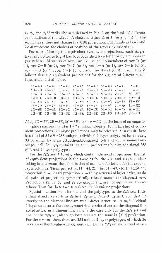
For ease of listing the equivalent two-layer projections, each single-layer projection in Fig. 4 has been identified by a letter or by a number inparentheses. Members of row 1 are equivalent to members of row D (or4 ) , r ow 2 :B (o r 2 ) , r ow 3 :C (o r 3 ) , r ow 4 :A (o r 1 ) , r ow 5 :E (o r 5 ) ,row 6:G (or 7) , row 7:F (or 6) , and row 8:H (or 8) . From th is i tfollows that the equivalent projections for the *1ft set of 2-layer struc-tures are as listed below.
1A:4D 2A:48 3A:4C 4A:4A. 5A:4E 6A:4G 7A:4F 8A:4H1B:2D 2B:28 3B:2C 4B:2A 5B:2E 6B:2G 7B:2F 8B:2H1C:3D 2C:38 3C :3C 4C:3A 5C :3E 6C :3G 7C:3F 8C :3HlD : lD 2D : rB 3D :1C 4D:1A 5D :1E 6D :1G 7D:1F 8D :1H1E:5D 2E:58 3E:5C 4E:5, \ 5E:5E 6E:5G 7E:5F 8E:5H1F:7D 2F:78 3F:7C 4F:7A 5F:7E 6F:7G 7F:7F 8F:7H1G:6D 2G:6B 3G:6C 4G:6A 5G:6E 6G:6G 7G:6F 8G:6H1H:8D 2H:8B 3H:8C 4H:8A 5H:8E 6H:8G 7H:8F 8H:8H
Also, 1D:7F,28:5E,3C:8H, and 4A:6G on the basis of an enant io-morphic relationship after 180" rotation about J,. From this list of equiv-alent projections 32 unique projections may be selected. As a result thereis a total oI 32X9:288 unique individual Z-layer polytypes for this set,33 of which have an orthorhombic-shaped cell and 255 a monoclinic-shaped cell. Set ,1r2 contains the same projections but an additional 288diff erent 2-1ay er polytypes.
For the f1f1 and -rt2 sets, which contain identical projections, the listof equivalent projections is the same as for the *fir and trtr2 sets aftertaking into account the substitution of numbers for letters for the secondlayer columns. Thus, projection 11:44,21:42,31:43, etc. In addition,projection 2l:12 and projection 31:13 by reversal of layer order, as doall pairs of projections symmetrically related across the diagonal row.Projections 22,33,55, and 88 are unique and are not equivalent to anyothers. Thus for these two sets there are 32 unique projections.
Special mention must be made of the polytvpes in the frfr set. Indi-vidual structures such as Er-Ia-l; *yTa-t, r,rla-3: fryIa-3, etc. that lieexactly on the diagonal line are true 1-layer structures. Also, individual2-layer structures that are symmetrically related across the diagonal lineare identical in 3-dimensions. This is the case only for the Efit set andnot for the i,fiz set, although both sets are the same in [010] projection.For the fr1*1set, then, there are 252 unique 2-layer polytypes, of which 26have an orthorhombic-shaped unit cell. In the Et*z set individual struc-

CHLORITE POLYTYPISM 1621
tures related across the diagonal may not necessarily be equivalent in 3-dimensions even though they have the same [010] projection. Thus, forthis set there are probably 306 unique 2-layet polytypes, of which 33 havean orthorhombic-shaped cell. It is possible that further equivalences ofprojections or of individual structures may exist, but the rarity of differ-ent natural 2-layer polytypes does not warrant a more exhaustive studyat this time.
For both the Efit and E1E2 sets the individual 2-layer structures that oc-cur in the small squares comprising the diagonal row are 1-layer in [010]projection and include all the previously reported natural 2-layer chloriteand vermiculite polytypes, except gonyerite. These polytypes may be de-scribed in the terminology of the present paper as follows:
Brindley et al. (1950) chlorite "C" rrIl.b-6ir2-IIb-4Mathieson and Walker (1954) vermiculite "r" irla-6:iz-Ia-6Mathieson and Walker (1954) vermiculite "q" trla-4:n-Ia-2Shirozu and Bailey (1966) vermiculite "s" e,rla-4:.irIa-6Lister (1966) cookeite (1) h-Ia-6:*z-Ia-6Lister (1966) cookeite (2) -rrTa-4:.h-Ia-6
Ddts (1966) dioctahedral chlorite rrl.Ib-4inJl.b-6
The same terminology can be extended to chlorites with more than twoIayers. The 3-layer crystal "D" described by Brindley et al,. (1950) con-tains only one structural layer type and would have the symbol er-IIb-6:*z-IIb-4:*Jfb-4.
Salrpr,B Dpscnrprror.T AND DATA FoR A NATURAL 2-LAyERCn-Cnronrra
An orthohexagonal 2-layer polytype of Cr-chlorite (kiimmererite) wasidentified in a sample contributed by Dr. R. A. Bell from the Erzincanprovince, Turkey. The chlorite occurs as incrustations on the walls ofvugs and cracks in a serpentinized basic rock. According to a chemicalanalysis by Brown and Bailey (1963) the chlorite has the composition(SfuAD (Mgo.oFeo.r2+Cro.zAIo.z)OrsH7.e. fn this well-crystall ized chloritesample several different polytypes have been recognized.
Approximately 90 crystals from the Erzincan sample have been ex-amined in this study and in the study by Brown and Bailey (1963). All ex-cept seven of the crystals have either regular 1-layer or semirandom struc-tures of the la layer type. The seven different crystals all contain 2-layerpackets, as indicated by the periodicity along h\l row lines, in which theidentification of the layer types is not obvious. Six of the seven crystalshave a regular stacking sequence along the a axis and give discretehl3n reflections. The other crystal has a disordered stacking sequenceas indicated by a continuous streak taking the place oI the hl3n refr"ec-
1622 JUDITH S, LISTI'R AND S, W. BAILEY
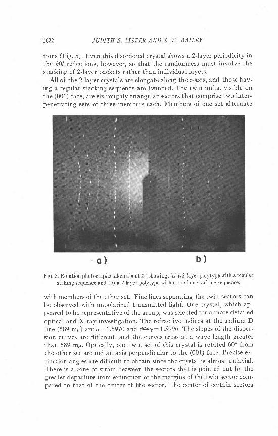
tions (Fig. 5). Even this disordered crystal shows a 2-layer periodicity inthe h\l, reflections, however, so that the randomness must involve thestacking of 2-layer packets rather than individual layers.
All of the Z-layer crystals are elongate along the z-axis, and those hav-ing a regular stacking sequence are twinned. The twin units, visible onthe (001) face, are six roughly triangular sectors that comprise two inter-penetrating sets of three members each. Members of one set alternate
o) b)
Frc. 5. Rotation photographs taken about Z* showing: (a) a 2-layer polytype with a regular
staking sequence and (b) a 2-Iayer polytype with a random stacking sequence.
with members of the other set. Fine lines separating the twin sectors canbe observed with unpolarized transmitted light. One crystal, which ap-peared to be representative of the group, was selected for a more detailedoptical and X-ray investigation. The refractive indices at the sodium Dline (589 mp) are a:1.5970 and Bczl:1.5996. The slopes of the disper-sion curves are different, and the curves cross at a wave length greaterthan 589 mp. Optically, on9 twin set of this crystal is rotated 60o fromthe other set around an axis perpendicular to the (001) face. Precise ex-tinction angles are difficult to obtain since the crystal is almost uniaxial.There is a zone of strain between the sectors that is pointed out by thegreater departure from extinction of the margins of the twin sector com-pared to that of the center of the sector. The center of certain sectors
CHLORITE POLYTYPISM 1623
shows no noticeable departure from extinction. The optics of this twinnedcrystal, and those of two others for which both optical data and X-rayprecession photographs were obtained, are anomalous. The extinctiondirections, or apparent extinction directions, are not parallel to theunique crystallographic directions as determined by X-ray methods.There is still some reservation as to whether this anomalous extinction isreal or is due to strain at the twin boundaries. For the crystal studied indetail the twin axis is believed to be [010] and the composition plane tobe (100) (also (130) and (130)).
The rotation photographs of a crystal having a regular stacking se-quence and one having a random stacking sequence (Fig. 5) prove theexistence of two-layer packets in both. The observation of 2-layer period-icity in the hUl reflections, rather than in the }kl reflections, requires thatthe layers in the packet be of different structural types, i.e. the octa-hedral cations must alternate between sites I and II in the talc or brucitesheets, or both of adjacent layers. The different nature of this chlorite isillustrated further by the observation that a small portion of a crystalcrushed for a powder photograph gives a pattern different from that ofany of the previously recorded theoretical or observed chlorite layertypes. Table 1 lists the observed and calculated d values for this powderpattern.
From precession photographs it was determined that the shape of theunit cell is orthorhombic, B:90". The refined cell parameters, a:5.335,b:9.240, and c: 28.735 A, *ere measured by the d method of Weisz et al,.(1948). The unit cell is centered on the (001) face; the reflections presentfollow the rule h+h:22. Precession photographs show a pseudo c-glideperpendicular to r, as evidenced by }kl,, l l2n reflections being weak. TheO6l, l*2n reflections are present although much weaker than the otherweakOkl,l, l2n types. The apparent space group of the twin crystal is C1.Because of the orthorhombic shape of the unit cell, twin reflectionsexactly superimpose on the normal reflections.
Several attempts were made to cut out an individual twin sector. Al-though both the small size of the sectors and imperfections caused by thecutting made it impossible to collect accurate intensity data by theWeissenberg method, some useful precession photographs of an un-twinned sector were obtained. These precession photographs confirmthat the structure has an orthorhombic-shaped 2-layer cell. In fact, zeroIevel photographs of the twinned crystal and of the cut sectors are iden-tical. This is as one would expect if the untwinned crystal has one or moresymmetry planes parallel to a and if the symmetry elements of two differ-ent twin sectors are superimposed by the twinning. As observed also forthe twinned crystal, the 0kl, ll2n refl.ections recorded from the un-

1624 JUDITH S. LISTER AND S. W. BAILEV
TABLE 1
Olsr,nwo axo Cetcur,.a.roo PowoBn De'rn lon rnn 2-L,wrn Cn-Cnromrn
d calc (A) d observed (A) Io
002004006110,020, t t l ,02lt 1 2 , 0 2 2713,023114,024115,025,008116,026177,0270.0 . 10 , 118,028200,130,2Ot,131119,029,202,132203,133204,1342 0 5 , 1 3 5 , 0 . 0 . 1 2206, 136223,043,207, t37225,O450.0 .14 ,2O9,1392 . 0 . 1 0 , 1 . 3 . 1 02 .0 . 12 ,1 .3 . 12310,240, 1s0312,242,1522 .0 . 13 , t .3 . t32 . 0 . 1 4 , 1 . 3 . 1 42 . 0 . 1 5 , 1 . 3 . 1 5330,060l . l . 18 , 0 .2 . 18 , 334, 0642 .2 . t5 ,0 .4 .15 , 336, 0660 . 0 . 2 02 . 0 . 1 7 , r . 3 . 1 7068,338
14.367 .t834 . 7 8 94. 5904.3984.1613 .8853.6003 3253.0682 8732.66r2 . 6 2 62.5692.5002 4292.330n 1 A <
2.1432 .0501 .9551 . 7 8 1| . 7 4 6I . / J J
1 .702r .6261 .5561.5401 .507r .4701 .436r .4271 .415
14.467 .2064.8094.6194.4124 1753.8993.6003 . 3 3 43 .0762 . 8 7 82.6642 . 6 2 62 . 5 7 52.50+2.4242.3402.2492. t432.0501 . 9 5 81 . 7 8 6t . 7 4 91 . 7 3 8| 704t .6291 .5581 5411 .507t .468r .4371.429| .416
910884
2I1t2
438
81071165i
1 1t 2
t+i a
J
I4i
112
twinned sector are weak and the 061, ll2n reflections are present but
very weak.
SrnucrunB DBronurNarroN
Intensity data were collected from the twinned crystal for comparison
with intensities of twinned trial models in the hope that the true struc-
ture and the twin relationship could be deduced. The crystal used had
CELORITE POLYTVPISM 1625
approximately the shape of a hexagon elongate along the a axis. Thelength of the crystal was 0.74 mm and its diameter ranged from 0.24 mmat the base to 0.13 mm at the tip. Only a small equidimensional portion
cut from the tip was used for most of the structure determination. Thevolume of the twin segments could be determined more accurately for thissegment. A total of 576 reflections was collected by the Weissenberg mul-tiple film pack technique from the )kl, h)l, hkU, and hk8 levels, and astandard multiple film pack scale was made for visually estimating the in-tensities. CuKa radiation was used rather than MoKa because the smallspacings of the reciprocal lattice along Z* did not permit the reflections tobe separated distinctly with MoKa radiation. A spherical absorption cor-rection, Lorentz-polarization correction, and an o1-otz separation correc-tion were applied to the data.
The ideal structural models pertinent to this study are those that havean orthorhombic-shaped cell. To facilitate selection of the "orthorhom-bic" polytypes, each of the individual single layers was described in termsof a vector whose magnitude and direction was established by joining
the lower OH of one talc sheet with the corresponding OH of the nexttalc sheet above. Combination of layers having equal and opposite vec-tors yields the structures that have orthorhombic-shaped cells. Thesevec to r comb ina t i ons a re 0 :0 , + l / 3 h : - t / 3 h , l t / 3 a ; - l f 3 ay
* l /3 az: - I f 3 a2, and l l /3 as: - t /3 or . The 21 d i f ferent [010] pro jec-tions represented by these "orthorhombic" structures were tested againstthe observed data by comparing Fo and F". From these tests the projec-tion group 1F (Fig. 4) gave considerably better agreement (R: 16/6 for77 reflections) than any other group (fi: 25 to 70/), and was selected asthe correct projection. Table2 includes the ideal coordinates for the [010]projection of this group. There are six unique "orthorhombic" polytypesthat have this [010] projection, four with the space group C1 and twowith the space groups Cc and Ccm2r. Although the apparent space group
of the crystal is C1, the observed pseudo c-glide requires that the trialmodel have basically a c-glide character. Of these six polytypes only theCc and Ccm2r ideal models, polytype designations *rIa-3zrz-Ila-6 and
h-Ia-I:.xrIIa-2 respectively, have any symmetry and are possible choicesfor the correct structure.
Further discrimination between the Cc and Ccm2t structures requiresthat the type of twinning be determined. Twinned models developed bythe twin operations of 180o rotation about an axis along one of the direc-tions [100], [110], [110], [310], or [310] (Sadanaga and Tak6uchi, 1961), byreflection across (100), and by 180" rotation around [010] were tested for
both of these structures by comparison of calculated twin intensities withthe observed values. To aid in making the choice, an additional 1081 ob-
r626 JUDITH S. LISTER AND S. W. BAILEY
TABLE 2
Arourc CoonotN.qrns ol Ilnar- aNo RnuNno Srnucrunr
Ideal" Refined
M g 1z
J
o
789
101 lt2
J l l
d
i
o
7c
o l23456789
101 1t2l . t
74l . )
o 1 6r7
0.000.000.000. ro/.167. l o /
.000
.000
.000
.333
. JJJ
.333
.333
. J . ' J
.000
.000
. ro,/
. ro /
.000
.000
. 1 1 0
.590
. 3 1 0
.333
.333
.230
.730, 5 J U
000.000. 4 1 0.890.690. l o , /
. 1 6 7
o.2ff i.760
0.000.333.667. l o , /
.500
.833
.000
.333
. oo /
.000
.333
. oo/
.333
.667
.000
.667
. ro /
.833
.000
.667
.760
.730
.500
.333
.667
. J O /
.600. )JJ
.000_ o o /
.7+O
.760
.500
. l o /
.833
0.600. J O /
0.000.000.000.250.250.250.500.500.500. , / J U
. / J U
. /.)u
. 1 5 4
. 1 5 4
.346
.346
.654
.654
.846
.846
.134
.134
.134
.214
.214
.366
.366
.366
.286
.286
.634
.634o.t4
. 7 1 4
.7 r4
0. 866.866
0.000.007.987.164. 1 8 0. r / o.021.984. 0 1 5.338.345.348
.336
.339
.004
.006
.170
. r70
.992
.992
.098<on
. 3 2 2
.333
.333
.215
.739
. J 1 4
.000
.000
.410
.911
.678
.167
. ro /
0 .278- t l 6
0.000.329.660.170.502.832.992.329.656.002. .t.t J
.668
.338
.672
.001
. o / r
.167
.837
.005
.671
.7ffi
.?30
.512
.333
. o o /
.570
.620
. 3 1 6
.000
. oo /
.732
. 7 5 8
.508
.167
.833
0 . 6 2 1.57r
0.000.002 : (Cr).996.250.250.250.498.496.497: (Cr).750.750.750
. t52
. 1 5 4
.348
.344
.656
.653
.844
.845
.132
. 1 3 8
. 1 3 8
.2t4
.214
. J / l
.358
.369
.286
.286
.640
.634
.640
. 7 1 4
. 7 1 4
0.859.872
'Coordinates are for polytype h-Ia-5:a-IIa-4 with basal oxygen triad rotated 60.Origin is in the brucite sheet.

CHLORITE POLYTYPISM
TABLE 2 (Continued.)
t627
Ideal Refined
181 0
20
o H 1z
3n
678o
101 1t213t4151 6
0.460.000.000
.333
.333
.333
.t67
.167
. ro /
.333
.000
. 1 6 7
. to /
. ro /
.333
. JJJ
. J J J
.167
.000
0. 333.000- oo/
.000
. JJJ
. oo,/
. r o /
.500
.833
.000333
.161
.500
.833
.000
.333
.667
.500
.333
0.866. / 6 0
.786
.967
.967
. 9 0 1
.034
.034
.034
.2t4
.286
.467
.467
.467
.534
.534
.534
. 7 1 4
.786
.386
.366
.378
.172
. 1 5 6
. 1 5 4
.333
.000
. 1 6 8
.140
. _too
.363
. J / l
.384
.t67
.000
0.450 0.328 0.867.000 .000 .786.000 .667 .786
.002 .967
.347 .967
.667 .967
.155 .034
.504 .034
.826 .034
.000 .214
.333 .286
.167 .467
.505 .467
.843 .467
.002 .s34
.327 .534
.648 .534
.500 .7 r4
.333 .786
served reflections from 11 levels along the a axis were used. These reflec-tions had been collected from the same elongate crystal before it was cut,using the Weissenberg multiple film pack technique and CuKa radiation.Absorption correction for a cylinder of the average diameter of the crystalwas applied as an approximation. Also, Lorentz-polarization and a1-42separation corrections were applied. On the basis of these twin model in-tensity calculations the Cc structure twinned by 180' rotation around
[010] was the only modjl that could not be proved invalid. This idealstructure has the c-glide perpendicular to the direction usually designatedas the r axis (5.3 A repeat) in layer silicates, and would require reversalof the customary r and I axes. The actual crystal, however, has only apseudo c-glide, so that all indices and coordinates reported here are forthe usual cell orientation.
A three-dimensional structure refinement was attempted for the Ccstructure, using the space group C1 because of the observed pseudo sym-metry. A least squares program was modified to twin the reciprocal lat-
tice and to build up intensities in the same manner as the twinned crys-
1628 TUDITH S, LISTER AND S. W. BAILEY
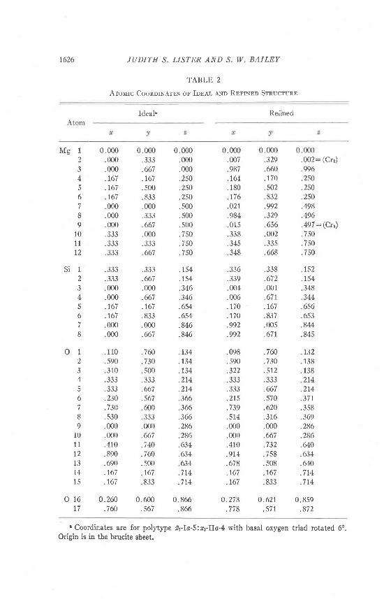
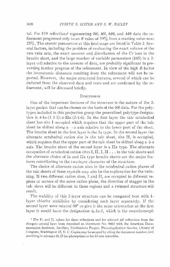
tal. For 519 reflectionsl representing0kl, hUl, hk0, and hk8 data the re-finement progressed only to an R value oI 19/6 from a starting value near25/6.The atomic parameters at this final stage are listed in Table 2. Sev-eral factors, including the problem of evaluating the exact volume of thetwo twin sets, the exact amount and distribution of the Cr ions in thebrucite sheet, and the large number of variable parameters (165) in a 2-Iayer cell relative to the amount of data, are probably significant in pre-venting further progress of the refinement. fn view of the high R factorthe interatomic distances resulting from the refinement will not be re-ported, Ifowever, the major structural features, several of which can bededuced from the observed data and tests and are confirmed by the re-finement, will be discussed briefly.
DrscussroN
One of the important features of the structure is the nature oI the 2-layer packet that can be chosen on the basis of the h)l data. For the poly-types included in this projection group the generalized polytype designa-tion is *;-Ia-(I-3-5):*-IIa-(2-4-6). In the first layer the talc octahedralsheet has site I occupied which requires that the upper part of the talcsheet be shifted along a -r axis relative to the lower part of the sheet.The brucite sheet in the first layer is the Io type. fn the second layer thealternate octahedral cation site in the talc sheet, site If, is occupied,which requires that the upper part of the talc sheet be shifted along a {*axis. The brucite sheet of the second layer is a IIa type. The alternateoccupation of octahedral cation cites I, fI, I, II . . . in the talc sheets andthe alternate choice of fa and IIo type brucite sheets are the major fea-tures contributing to the two-layer character of the structure.
The choice of alternate cation sites in the octahedral cation planes ofthe talc sheets of these crystals may also be the explanation for the twin-ning. If two different cation sites, I and II, are occupied in difierent re-gions or sectors of the same cation plane, the direction of stagger in thetalc sheet will be difierent in those regions and a twinned structure willresult.
The stability of this 2-layer structure can be compared best with 1-layer chlorite stabilities by considering each layer separately. If thesecond layer were rotated 60" to give it the same orientation as the firstlayer it would have the designation i,yIa-S, which is the enantiomorph
1 The Fs and F" values for these reflections and for selected /zfrl reflections from theelongate crystal have been deposited as Document No. 9663 with the American Docu-rnentation Institute, Auxiiiary Publications Project, Photoduplication Service, Library ofCongress, Washington 25, D. C. Copies may be secured by citing the document number, andremitting in advance $1.25 for photoprints or for 35 mm microfilm.

CHLORITE POLYTYPISM 1629
of the first layet x.yla-3. All Io-odd layer types, after 180" rotation aboutthe I axis, are equivalent to, and should have the same relative stabilitiesas, the Ib (P:97o) layer types described in Part I. As pointed out in Part
III (Shirozu and Bailey, 1965), the talc sheet contacts are different on op-posite sides of the brucite sheet in such layers. This asymmetric position-
ing of the talc sheets relative to the brucite sheets is maintained through-out the 2-Iayer packets studied here. Adoption in irregular sequencethroughout the crystal of the three talc to brucite contacts that are pos-
sible for each layer would preserve the structural layer types and theirasymmetric geometry, and would explain the streaking ol kl3n reflec-
tions observed for the one crystal illustrated in Figure 50. Even in this
crystal there is a 2-layer periodicity that indicates the same layer typespresent and a regular alternation of occupation of the octahedral cation
sites I and II in the talc and brucite sheets of adjacent layers.The pseudo c-glide is a feature inherent in the structure. It is not
caused by twinning because the }hl,ll2n refl.ections are also present on
films of the untwinned segment. Rotation of the basal oxygen triads of
the talc sheet, a feature common in layer silicates, does not destroy the
c-glide that is present in the ideal model. More likely, the c-glide is de-
stroyed by a special and uneven distribution of scattering power over cat-
ion sites related by a c-glide. Neither the tetrahedral cations nor the
octahedral cations of the talc sheet can provide such an arrangement.
Therefore the c-glide must be destroyed by a special distribution of Cr
ions in the brucite sheet so that the Cr ions in alternating brucite sheets
are not related by a c-glide. This is a feasible explanation because tests
using 001 data to determine the distribution of octahedral cations be-
tween the talc and brucite sheets show that the Cr ion is entirely within
the brucite sheet. This is also the case for the l-layer polytype from this
sample studied in Part II.The concept of a special distribution of Cr ions in the brucite sheet
was taken into consideration in testing the twinned models of the Cc and
Ccm2t structures and in choosing the Cc structure as the correct trial
model. In a 2-layer structure there are six different octahedral cation
sites in the brucite sheets, three in the brucite sheet of the first layer and
three in the brucite sheet of the second layer (Fig. 6o). The two Crions,
one for each layer, that are available for distribution between these sites
can be arranged in nine different Cr distribution patterns. The Cr dis-
tribution may preserve the c-glide or destroy it. The six Cr combinations
that violate the c-glide are designated 1-5, l-6, 24, 2-6, 3-4, and 3-5.
From the tests of the twinned trial models it was possible to eliminate
four of these combinations. A final choice between Cr distribution pat-
terns 2-6 and 3-5 could not be made. For hkl,l:2n, calculated data for

1630 JUDITH S. LISTER AND S. W. BAILEY
O r i g i n
s i
- B r u c i l c -
_ s i
O r i g i n- T o l c
b ) l - l o y c r 8 l r u c t u r ! ,
I o
Frc. 6. Diagram of planes of cations. The arrow connects superimposing cations. (a) 2-Iayer structure,Ia-IIa. (b) l-tayer structure, Ia-4 (Brown and Bailey, 1963). Chromiumposition in the brucite sheet is marked with an r.
the 2-6 and 3-5 patterns are exactly the same, and for hkl, ll2n, thecalculated data are the same after twinning.
The restriction of Cr to sites 2 and 6 (or 3 and 5) may give a clue to pos-sible Al ordering in the tetrahedral sheet. Brown and Bailey (1963) foundlocal charge balance in the structure of a 1-layer Cr chlorite, Ia-4, suchthat the Cr3+ ion was located directly between the tetrahedral sites in thetalc sheets above and below that contained the most substitution of AIB+for Sia+ (Fig. 6D). By analogy with this structure Al may be inferred tosubstitute for Si in the tetrahedral site of the talc sheet directly below theCr-rich brucite cation site 2 (or 5). Brucite cation site 6 (or 3) is a site ofno cation repulsion and would also be a favorable site for Cr ions.
Although twinning prevented complete refinement, it was still possible
/xs i
o ) 2 - l o y c r s l r u c l u r c rI o - I I o

CHLORITE POLYTYPISM 1631
to determine the direction and approximate amount of rotation of thetetrahedra. As in other Iayer silicate structures, the basal oxygen triad ofthe talc sheet has rotated from its ideal position in the direction to ob-tain optimum hydrogen bonds between the tetrahedral basal oxygens andthe brucite hydroxyls. The amount of rotation is approximately 6", whichis the same as that reported by Brown and Bailey (1963) for a 1-layer Crchlorite from the same locality. The presence of very weak 061, l#2nre-flections also suggest that some atoms that ideally repeat at intervals of
D/3 must be displaced from this ideal relationship. These displacementscould not be determined.
AcKNoWEDGMENTS
This study was supported in part by grant ll76-L2 from the Petroleum Research Fund,
administered by the American Chemical Society, in part by National Science Foundation
grant GP-4843, and in part by the Research Committee of the Graduate School from funds
supplied by the Wisconsin Alumni Research Foundation. Computations were carried out in
the University of Wisconsin Computing Center, which is also supported in part by National
Science Foundation funds.
RelennNcns
B.arr.rv, S. W. ,tNo B. E. Bnowx (1962) Chlorite polytypism: I. Regular and semi-random
one-layer structures. Amer. M iner al'. 47, 819-850.BnrNor-nv, G. W. (1961) Chlorite minerals. In Brown, G., ed., The X-roy ldentif'cation and'
Crystol Structures oJ Cl'ay Minerals (2nd ed.), chap. 6. Mineral. Soc , London.--, Bnnvl Oucnror, axo K. RosrxsoN (1950) Polymorphism of the chlorites. I.
Ordered structures. A cta Crystal'Io gr. 3, 408-416.
BnowN, B. E. ,qNn S. W. B,trlnv (1963) Chlorite polytypism: II. Crystal structure of a
one layer Cr-chlorite. Amev. Mineral. 48r 42-6t.
Dnrrs, V. A. (1966) X-ray investigation of some rare polytypes of layer s\\cales. Acta
Crystal logr.2 l , A172.FnoNorr-, C. (1955) Two chlorites: gonyerite and melanolite. Amer. Mi.nerol. '410' 1090-1094.
LrsrER, Juorrn S. (1966) The crysta| structure oJ two chtror'ites. Ph.D. Thesis, Univ. Wiscon-
sln.M.nrrrrrsoN, A. McL. eNo G. F. Wer.r<en (1954) Crysta,
lite. Amer. M ineral,. 39, 231-255.
SaolNece, R. aNn Y. Tar6ucrt (1961) Polysynthetic116. 406 429.
structure of magnesium-vermicu-
twinning of micas. Z. Kristdlogr.
Srlnozu, H.tnuo ,lNo S. W. Berr-rv (1965) Chlorite polytypism: III. Crystal structure of
an orthohexagonal iron chlorite. Amer. Mineral.50' 868-885.-- (1966) Crystal structure of a two-layer Mg-vermiculite. Amer. Mineral'.51, ll24-
1143.Wrrsz, O., W. Cocnnex eNo W. F. Cor,n (1948) The accurate determination of cell dimen-
sions from single-crystal X-ray photographs. Acta Crystallogr. l' 83-88.
Monuscript recei.red, April' 11, 1967 ; acceptd Jor publ,icotion June 30, 1967.