China ··Xingyue Group
30
China·Xingyue Group (Xingyueshen)Brand XYKD260-1 GO-KART Repair Manual China·Xingyue Group Shanghai Xingyue Power Machinery Co., Ltd
Transcript of China ··Xingyue Group

China····Xingyue Group
(Xingyueshen)Brand
XYKD260-1
GO-KART Repair Manual
China····Xingyue Group Shanghai Xingyue Power Machinery Co., Ltd
(1)
Foreword
To enable users and repairing personnel of Xingyue products to better understand maintenance,
adjustment and repair technologies of XYKD260-1GO-KART under the brand of Xingyue, we have
specially prepared this manual, which is intended to be used by users who have purchased
XYKD260-3GO-KART and repair personnel for the purpose of technical guidance only.
All information, charts, various data and performance indicators contained in this manual are latest
product data. Shanghai Xingyue Power Machinery Co., Ltd reserves the right to modify the manual at
any time without notice. Any part of the manual belongs to Shanghai Xingyue Power Machinery Co.,
Ltd and shall not be reproduced by any institution or individual with prior written consent of the
Company.
(2)
Table of Contents
Foreword ………………………………………………………………………………………………………………………………………………………………………………………………………………………………………………………………………………………………………………………………………………………………………… 1
Table of Contents ………………………………………………………………………………………………………………………………………………………………………………………………………………………………………………………………………………………………………………………………………… 2
One. Machine number imprinting location …………………………………………………………………………………………………………………………………………………………………………………………………………………… 3
Two. Main technical parameters………………………………………………………………………………………………………………………………………………………………………………………………………………………………………………………………………… 4
Three. Standard torque value…………………………………………………………………………………………………………………………………………………………………………………………………………………………………………………………………………………… 7
Four. Lubricant and lubrication diagram ……………………………………………………………………………………………………………………………………………………………………………………………………………………………… 8
Five.
Troubleshooting
1....Unable to start or difficult to start …………………………………………………………………………………………………………………………………………………… 9
2....Powerless within high speed range and the speed does not increase…………………… 10
3....Abnormal engine operation((((mainly low speed and idle speed))))………………………………………… 12
4....Abnormal engine operation(mainly high speed) ……………………………………………………………………………………………… 13
5....The speed can increase, but the vehicle can not start ………………………………………………………………………… 14
6. Poor charging ……………………………………………………………………………………………………………………………………………………………………………………………………………………………………………………………… 15
Six.
Six
Adjustment and
repair
1....Regular inspection and service ………………………………………………………………………………………………………………………………………………………………………… 16
2
Special
items
1))))Brake system ………………………………………………………………………………………………………………………………………………………………………………………………………… 17
2))))Accelerator operation system ………………………………………………………………………………………………………………………………………… 17
3))))Reverse gear operation system ……………………………………………………………………………………………………………………………… 18
4))))Parking operation system …………………………………………………………………………………………………………………………………………………… 18
5))))Wheel ………………………………………………………………………………………………………………………………………………………………………………………………………………………………………… 18
6))))Damping system …………………………………………………………………………………………………………………………………………………………………………………… 19
7))))Rear drive system …………………………………………………………………………………………………………………………………………………………………………………… 19
8))))Stabilizer bar ………………………………………………………………………………………………………………………………………………………………………………………………………… 19
9))))Electrical system ……………………………………………………………………………………………………………………………………………………………………………………………… 20
10))))Engine retarder fixing structure …………………………………………………………………………………………………………………… 24
11))))Engine ……………………………………………………………………………………………………………………………………………………………………………………………………………………………… 24
12))))Cooling system ……………………………………………………………………………………………………………………………………………………………………………………………… 29
(3)
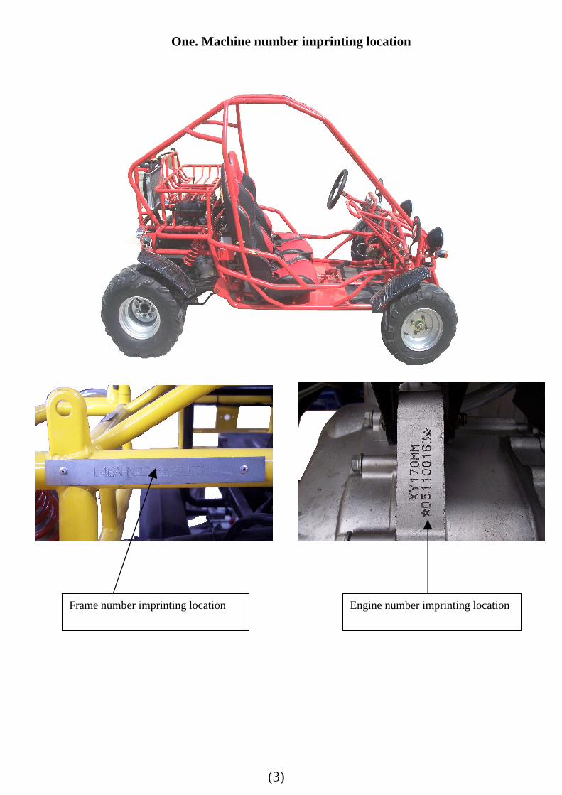
One. Machine number imprinting location
Frame number imprinting location Engine number imprinting location
(4)
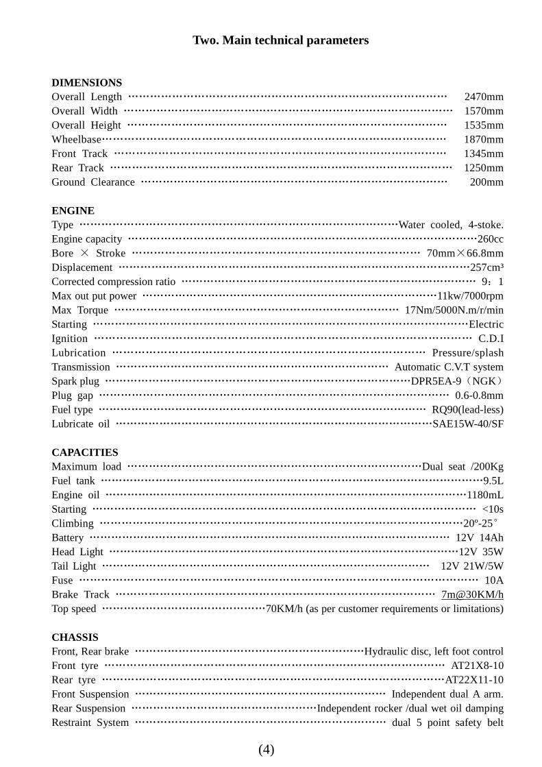
Two. Main technical parameters
DIMENSIONS Overall Length …………………………………………………………………………… 2470mm Overall Width ……………………………………………………………………………… 1570mm Overall Height …………………………………………………………………………… 1535mm Wheelbase………………………………………………………………………………… 1870mm Front Track ……………………………………………………………………………… 1345mm Rear Track ………………………………………………………………………………… 1250mm Ground Clearance ………………………………………………………………………… 200mm ENGINE Type ……………………………………………………………………………Water cooled, 4-stoke. Engine capacity ……………………………………………………………………………………260cc Bore × Stroke …………………………………………………………………… 70mm×66.8mm Displacement ……………………………………………………………………………………257cm³ Corrected compression ratio ……………………………………………………………………… 9:1 Max out put power ………………………………………………………………………11kw/7000rpm Max Torque …………………………………………………………………… 17Nm/5000N.m/r/min Starting …………………………………………………………………………………………Electric Ignition ………………………………………………………………………………………… C.D.I Lubrication ………………………………………………………………………… Pressure/splash Transmission ………………………………………………………………… Automatic C.V.T system Spark plug …………………………………………………………………………DPR5EA-9(NGK) Plug gap …………………………………………………………………………………… 0.6-0.8mm Fuel type ……………………………………………………………………………… RQ90(lead-less) Lubricate oil ……………………………………………………………………………SAE15W-40/SF CAPACITIES Maximum load ………………………………………………………………………Dual seat /200Kg Fuel tank ……………………………………………………………………………………………9.5L Engine oil ………………………………………………………………………………………1180mL Starting …………………………………………………………………………………………… <10s Climbing ………………………………………………………………………………………20º-25° Battery ……………………………………………………………………………………… 12V 14Ah Head Light ……………………………………………………………………………………12V 35W Tail Light ……………………………………………………………………………… 12V 21W/5W Fuse ……………………………………………………………………………………………… 10A Brake Track …………………………………………………………………………… 7m@30KM/h Top speed ………………………………………70KM/h (as per customer requirements or limitations) CHASSIS Front, Rear brake ………………………………………………………Hydraulic disc, left foot control Front tyre ………………………………………………………………………………… AT21X8-10 Rear tyre …………………………………………………………………………………AT22X11-10 Front Suspension …………………………………………………………… Independent dual A arm. Rear Suspension ……………………………………………Independent rocker /dual wet oil damping Restraint System …………………………………………………………… dual 5 point safety belt
(5)
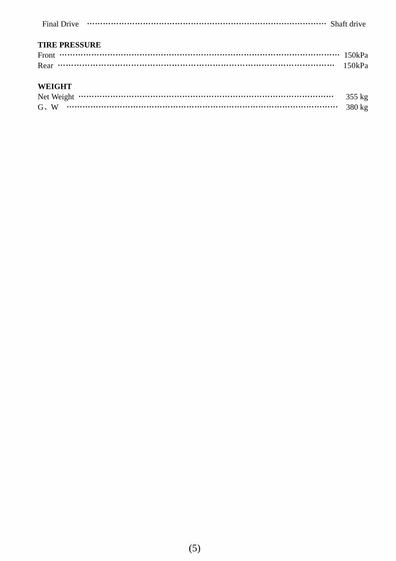
Final Drive ……………………………………………………………………………… Shaft drive
TIRE PRESSURE Front …………………………………………………………………………………………… 150kPa Rear ………………………………………………………………………………………… 150kPa WEIGHT Net Weight …………………………………………………………………………………… 355 kg G、W ………………………………………………………………………………………… 380 kg
(6)
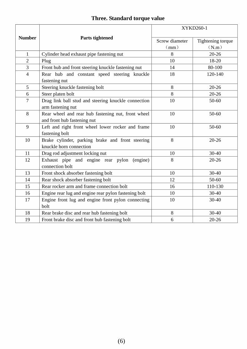
Three. Standard torque value
Number Parts tightened
XYKD260-1
Screw diameter(mm)
Tightening torque(N.m)
1 Cylinder head exhaust pipe fastening nut 8 20-26 2 Plug 10 18-20 3 Front hub and front steering knuckle fastening nut 14 80-100 4 Rear hub and constant speed steering knuckle
fastening nut 18 120-140
5 Steering knuckle fastening bolt 8 20-26 6 Steer platen bolt 8 20-26 7 Drag link ball stud and steering knuckle connection
arm fastening nut 10 50-60
8 Rear wheel and rear hub fastening nut, front wheel and front hub fastening nut
10 50-60
9 Left and right front wheel lower rocker and frame fastening bolt
10 50-60
10 Brake cylinder, parking brake and front steering knuckle horn connection
8 20-26
11 Drag rod adjustment locking nut 10 30-40 12 Exhaust pipe and engine rear pylon (engine)
connection bolt 8 20-26
13 Front shock absorber fastening bolt 10 30-40 14 Rear shock absorber fastening bolt 12 50-60 15 Rear rocker arm and frame connection bolt 16 110-130 16 Engine rear lug and engine rear pylon fastening bolt 10 30-40 17 Engine front lug and engine front pylon connecting
bolt 10 30-40
18 Rear brake disc and rear hub fastening bolt 8 30-40 19 Front brake disc and front hub fastening bolt 6 20-26
(7)
Four. Lubricant and lubrication drawing
1. Engine part
Used where Description Remark
Crank case 15W/40SF designated Full capacity: 1.0L
Gear box 15W/40SF designated Full capacity:0. 22L
Clutch driven surface and mobile driven surface
Li-based grease ZL-3H(SY 1413) 4.5~5.0g
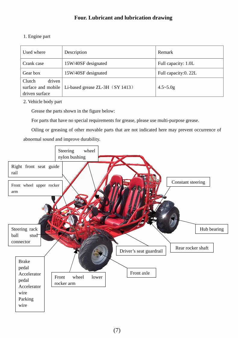
2. Vehicle body part
Grease the parts shown in the figure below:
For parts that have no special requirements for grease, please use multi-purpose grease.
Oiling or greasing of other movable parts that are not indicated here may prevent occurrence of
abnormal sound and improve durability.
Steering rack ball stud connector
Steering wheel nylon bushing
Brake pedal Accelerator pedal Accelerator wire Parking wire
Front wheel lower rocker arm
Front wheel upper rocker
arm
Front axle
Driver’s seat guardrail
Constant steering
Hub bearing
Rear rocker shaft
Right front seat guide rail
(8)
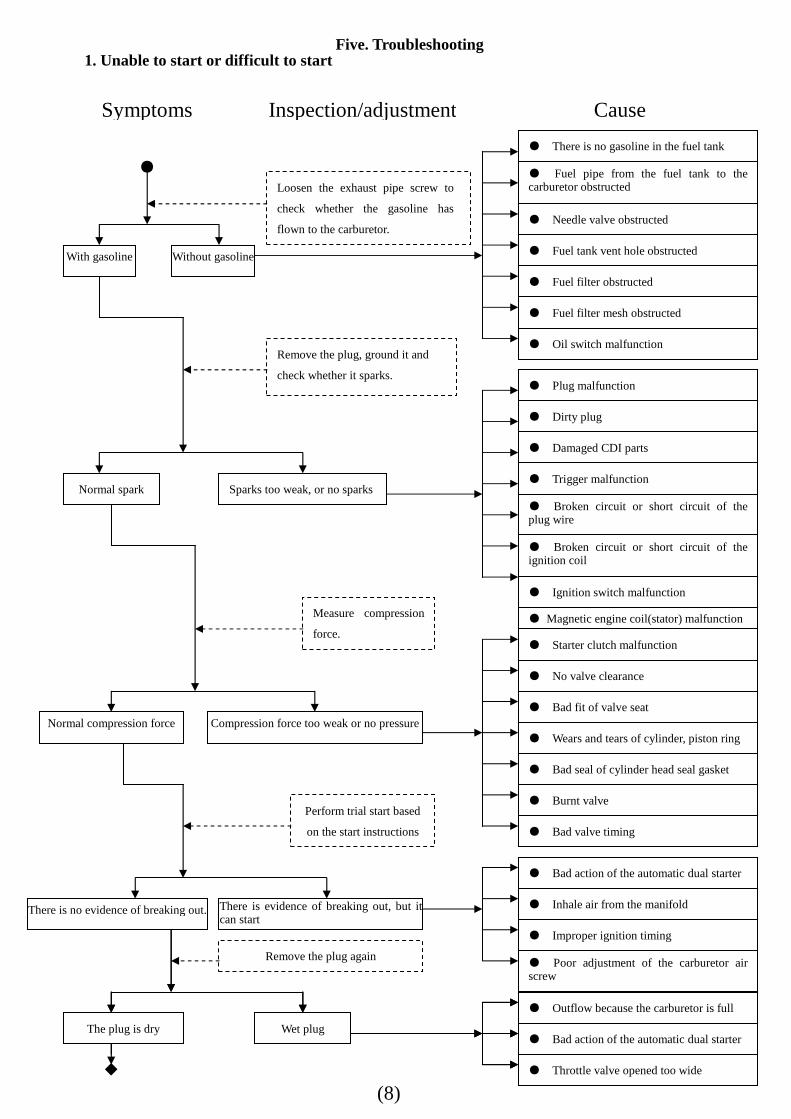
Five. Troubleshooting 1. Unable to start or difficult to start
Loosen the exhaust pipe screw to
check whether the gasoline has
flown to the carburetor.
Remove the plug, ground it and
check whether it sparks.
With gasoline
● ● Fuel pipe from the fuel tank to the carburetor obstructed
● Needle valve obstructed
● Fuel tank vent hole obstructed
● Fuel filter obstructed
● Fuel filter mesh obstructed
● Oil switch malfunction
● Plug malfunction
● Damaged CDI parts
● Dirty plug
● Trigger malfunction
● Broken circuit or short circuit of the plug wire
● Broken circuit or short circuit of the ignition coil
● Ignition switch malfunction
● Starter clutch malfunction
● No valve clearance
● Wears and tears of cylinder, piston ring
● Bad seal of cylinder head seal gasket
● Burnt valve
● Bad valve timing
● Bad action of the automatic dual starter
Without gasoline
● Bad fit of valve seat
● Inhale air from the manifold
● Improper ignition timing
● Poor adjustment of the carburetor air screw
● 化油器过满溢出
● 自动双起动机的动作不良
● 节流阀开得太大
Normal spark Sparks too weak, or no sparks
Measure compression
force.
Normal compression force Compression force too weak or no pressure
Perform trial start based
on the start instructions
There is no evidence of breaking out.There is evidence of breaking out, but it can start
Remove the plug again
火花塞是干的 火花塞湿
◆
● Outflow because the carburetor is full
● Bad action of the automatic dual starter
● Throttle valve opened too wide
The plug is dry Wet plug
◆
Symptoms Inspection/adjustment Cause
● There is no gasoline in the fuel tank
● Magnetic engine coil(stator) malfunction
(9)
Symptoms Inspection/adjustment
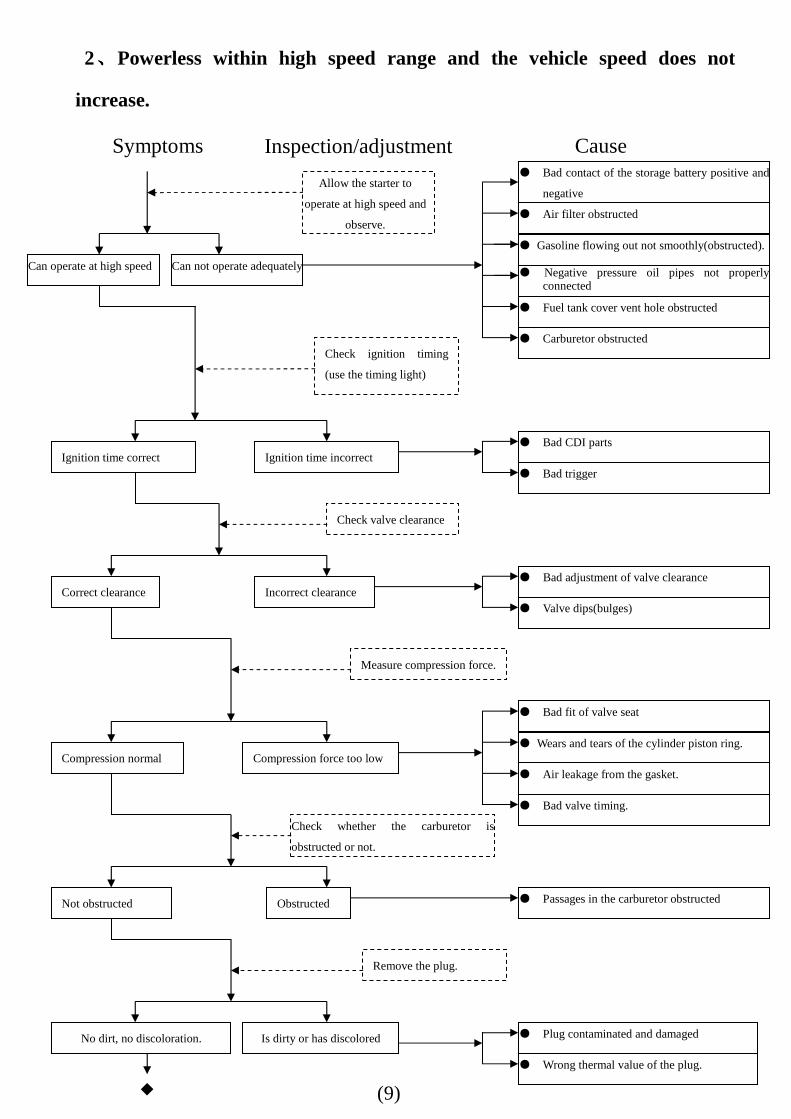
2、、、、Powerless within high speed range and the vehicle speed does not
increase.
Cause
◆
Check ignition timing
(use the timing light)
。
● Bad contact of the storage battery positive and
negative
● Air filter obstructed
● Fuel tank cover vent hole obstructed
● Bad CDI parts
● Bad trigger
Ignition time correct Ignition time incorrect
● Bad adjustment of valve clearance
● Valve dips(bulges)
Correct clearance Incorrect clearance
● Wears and tears of the cylinder piston ring.
● Air leakage from the gasket.
Compression normal Compression force too low
● Passages in the carburetor obstructed Not obstructed Obstructed
● Plug contaminated and damaged
● Wrong thermal value of the plug.
No dirt, no discoloration. Is dirty or has discolored
● Bad fit of valve seat
● Bad valve timing.
Check valve clearance
Measure compression force.
Remove the plug.
Check whether the carburetor is
obstructed or not.
Can operate at high speed
● Gasoline flowing out not smoothly(obstructed).
● Negative pressure oil pipes not properly connected
● Carburetor obstructed
Can not operate adequately
Allow the starter to
operate at high speed and
observe.
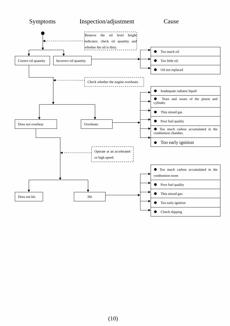
(10)
Inspection/adjustment
Check whether the engine overheats.
● Oil not replaced
● Thin mixed gas
● Poor fuel quality Does not overheat Overheats
Does not hit. Hit
Operate at an accelerated
or high speed.
Symptoms Cause
Remove the oil level height
indicator; check oil quantity and
whether the oil is dirty.
Correct oil quantity
●
● Too much oil
● Too little oil. Incorrect oil quantity.
● Tears and wears of the piston and cylinder.
● Too much carbon accumulated in the combustion chamber.
● Too early ignition
● Thin mixed gas.
● Too early ignition
● Poor fuel quality
● Too much carbon accumulated in the
combustion room
● Clutch slipping
● Inadequate radiator liquid
(11)
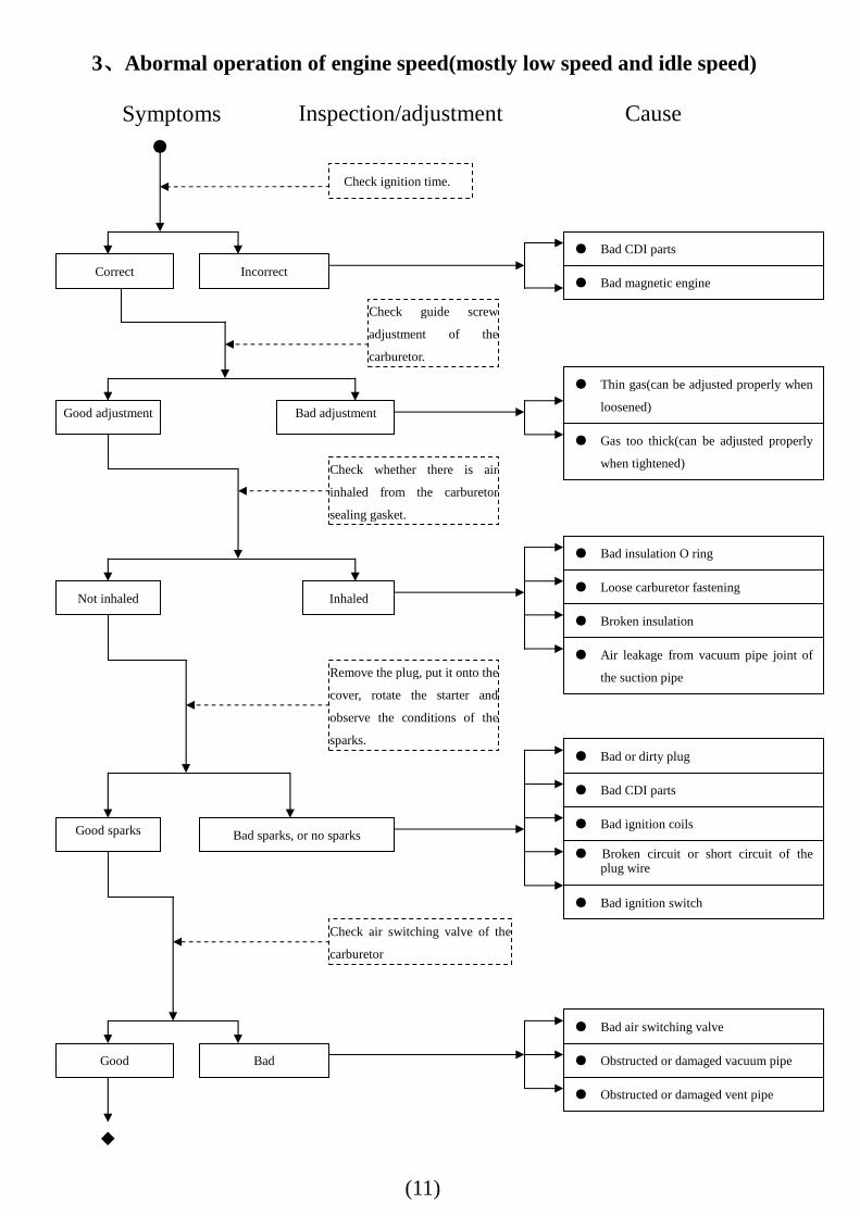
Symptoms Inspection/adjustment
3、、、、Abormal operation of engine speed(mostly low speed and idle speed)
故障原因故障原因故障原因故障原因
Check ignition time.
Correct
●
● Bad CDI parts
● Bad magnetic engine Incorrect
● Thin gas(can be adjusted properly when
loosened)
● Gas too thick(can be adjusted properly
when tightened)
Good adjustment Bad adjustment
● Loose carburetor fastening
● Broken insulation
Not inhaled Inhaled
● Bad insulation O ring
● Air leakage from vacuum pipe joint of
the suction pipe
Check guide screw
adjustment of the
carburetor.
Check whether there is air
inhaled from the carburetor
sealing gasket.
Remove the plug, put it onto the
cover, rotate the starter and
observe the conditions of the
sparks.
Good sparks Bad sparks, or no sparks ● Bad ignition coils
● Broken circuit or short circuit of the plug wire
● Bad CDI parts
● Bad or dirty plug
● Bad ignition switch
● Obstructed or damaged vent pipe
Good
● Bad air switching valve
● Obstructed or damaged vacuum pipe Bad
◆
Check air switching valve of the
carburetor
Cause
(12)
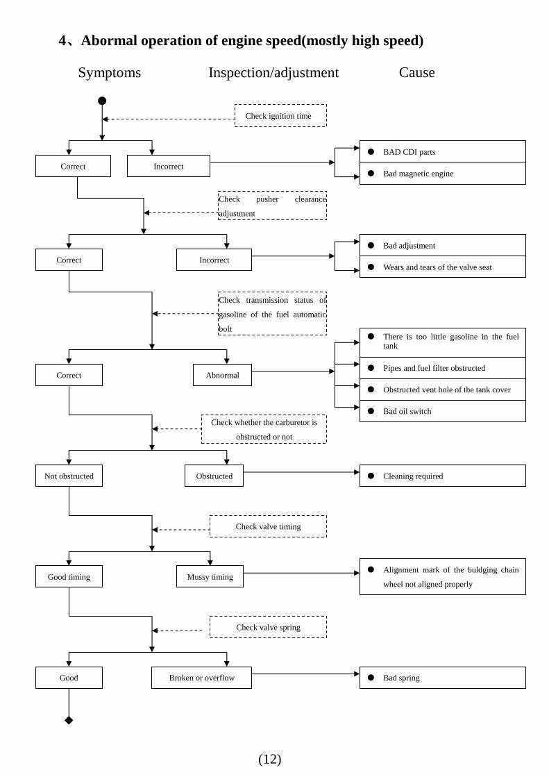
Symptoms Inspection/adjustment
4、、、、Abormal operation of engine speed(mostly high speed)
Check ignition time
Correct
●
● BAD CDI parts
● Bad magnetic engine Incorrect
● Bad adjustment
● Wears and tears of the valve seat Correct Incorrect
● Pipes and fuel filter obstructed
● Obstructed vent hole of the tank cover
Correct Abnormal
● There is too little gasoline in the fuel tank
● Bad oil switch
Check pusher clearance
adjustment
Check transmission status of
gasoline of the fuel automatic
bolt
Cause
● Cleaning required Not obstructed Obstructed
Check whether the carburetor is
obstructed or not
● Alignment mark of the buldging chain
wheel not aligned properly Good timing Mussy timing
Check valve timing
● Bad spring Good Broken or overflow
Check valve spring
◆
(13)
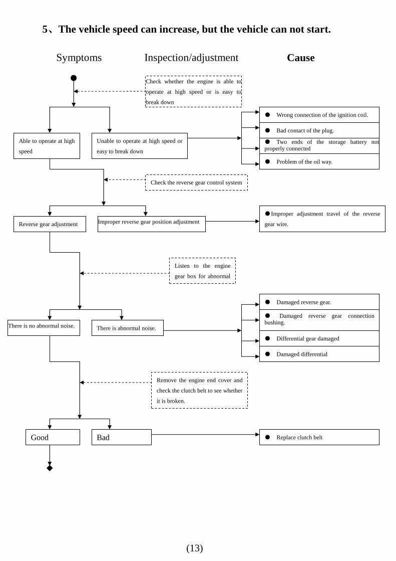
Symptoms Inspection/adjustment
5、、、、The vehicle speed can increase, but the vehicle can not start.
Check whether the engine is able to
operate at high speed or is easy to
break down
Able to operate at high
speed
●
● Wrong connection of the ignition coil.
● Bad contact of the plug.
Unable to operate at high speed or
easy to break down
Reverse gear adjustment
Check the reverse gear control system
Cause
●Improper adjustment travel of the reverse
gear wire. Improper reverse gear position adjustment
● Two ends of the storage battery not properly connected
● Problem of the oil way.
There is no abnormal noise.
● Replace clutch belt
There is abnormal noise.
Listen to the engine
gear box for abnormal
● Differential gear damaged
Good
● Damaged reverse gear.
● Damaged reverse gear connection bushing.
Bad
◆
Remove the engine end cover and
check the clutch belt to see whether
it is broken.
● Damaged differential
(14)
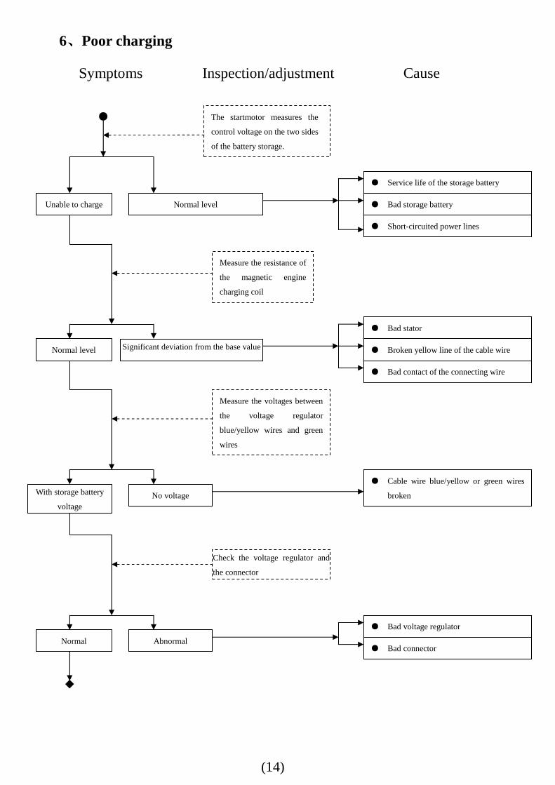
Symptoms Inspection/adjustment
6、、、、Poor charging
The startmotor measures the
control voltage on the two sides
of the battery storage.
Unable to charge
●
● Service life of the storage battery
● Bad storage battery Normal level
Cause
● Short-circuited power lines
● Bad contact of the connecting wire
Normal level
● Bad stator
● Broken yellow line of the cable wire Significant deviation from the base value
Measure the resistance of
the magnetic engine
charging coil
With storage battery
voltage
● Cable wire blue/yellow or green wires
broken No voltage
Measure the voltages between
the voltage regulator
blue/yellow wires and green
wires
Normal
● Bad voltage regulator
● Bad connector Abnormal
Check the voltage regulator and
the connector
◆
(15)
Six. Inspection. Adjustment
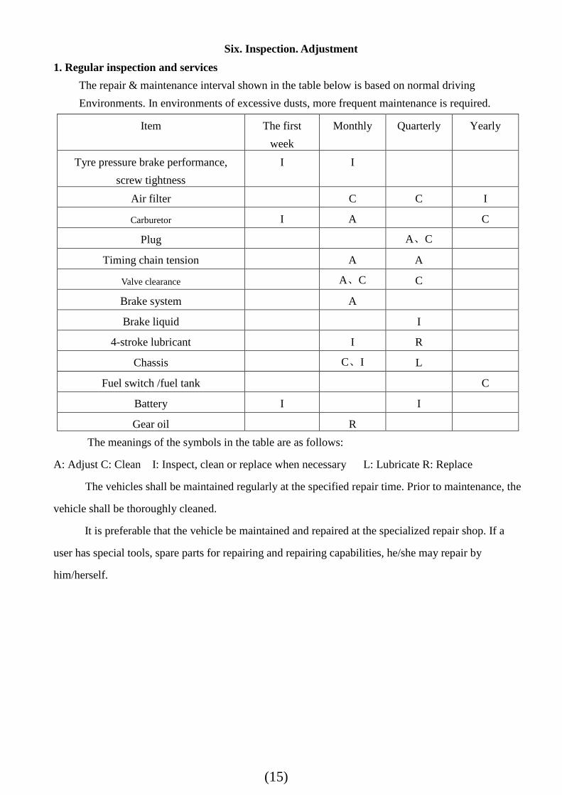
1. Regular inspection and services
The repair & maintenance interval shown in the table below is based on normal driving
Environments. In environments of excessive dusts, more frequent maintenance is required.
The meanings of the symbols in the table are as follows:
A: Adjust C: Clean I: Inspect, clean or replace when necessary L: Lubricate R: Replace
The vehicles shall be maintained regularly at the specified repair time. Prior to maintenance, the
vehicle shall be thoroughly cleaned.
It is preferable that the vehicle be maintained and repaired at the specialized repair shop. If a
user has special tools, spare parts for repairing and repairing capabilities, he/she may repair by
him/herself.
Item The first
week
Monthly Quarterly Yearly
Tyre pressure brake performance,
screw tightness
I I
Air filter C C I
Carburetor I A C
Plug A、C
Timing chain tension A A
Valve clearance A、C C
Brake system A
Brake liquid I
4-stroke lubricant I R
Chassis C、I L
Fuel switch /fuel tank C
Battery I I
Gear oil R
(16)
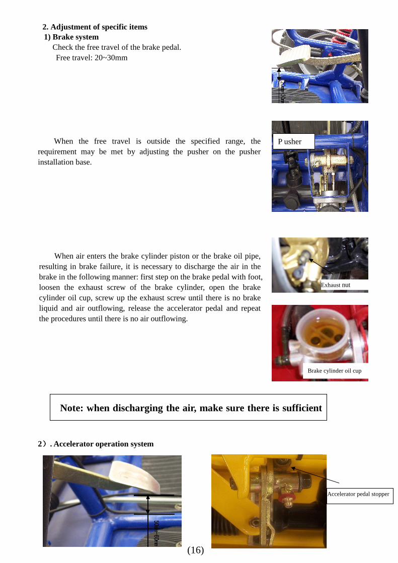
2. Adjustment of specific items 1) Brake system
Check the free travel of the brake pedal. Free travel: 20~30mm
When the free travel is outside the specified range, the requirement may be met by adjusting the pusher on the pusher installation base.
When air enters the brake cylinder piston or the brake oil pipe, resulting in brake failure, it is necessary to discharge the air in the brake in the following manner: first step on the brake pedal with foot, loosen the exhaust screw of the brake cylinder, open the brake cylinder oil cup, screw up the exhaust screw until there is no brake liquid and air outflowing, release the accelerator pedal and repeat the procedures until there is no air outflowing.
2)))). Accelerator operation system
Note: when discharging the air, make sure there is sufficient
Accelerator pedal stopper
Brake cylinder oil cup
Exhaust nut
P usher
(17)
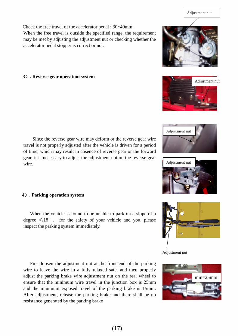
Check the free travel of the accelerator pedal : 30~40mm. When the free travel is outside the specified range, the requirement may be met by adjusting the adjustment nut or checking whether the accelerator pedal stopper is correct or not. 3)))). Reverse gear operation system
Since the reverse gear wire may deform or the reverse gear wire travel is not properly adjusted after the vehicle is driven for a period of time, which may result in absence of reverse gear or the forward gear, it is necessary to adjust the adjustment nut on the reverse gear wire.
4)))). Parking operation system
When the vehicle is found to be unable to park on a slope of a
degree ≤18°, for the safety of your vehicle and you, please inspect the parking system immediately.
First loosen the adjustment nut at the front end of the parking wire to leave the wire in a fully relaxed sate, and then properly adjust the parking brake wire adjustment nut on the real wheel to ensure that the minimum wire travel in the junction box is 25mm and the minimum exposed travel of the parking brake is 15mm. After adjustment, release the parking brake and there shall be no resistance generated by the parking brake
Adjustment nut
Adjustment nut
Adjustment nut
Adjustment nut
min=25mm
Adjustment nut
(18)
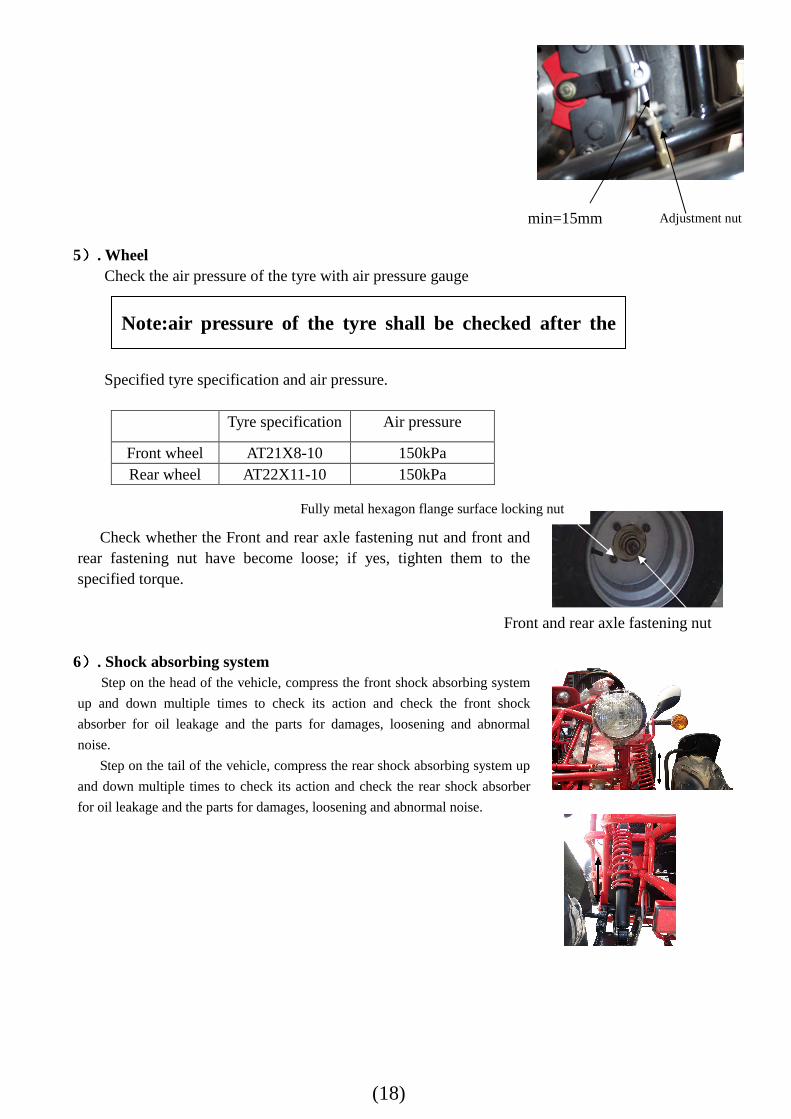
5)))). Wheel
Check the air pressure of the tyre with air pressure gauge Specified tyre specification and air pressure.
Tyre specification Air pressure
Front wheel AT21X8-10 150kPa Rear wheel AT22X11-10 150kPa
Check whether the Front and rear axle fastening nut and front and
rear fastening nut have become loose; if yes, tighten them to the specified torque.
6)))). Shock absorbing system
Step on the head of the vehicle, compress the front shock absorbing system
up and down multiple times to check its action and check the front shock
absorber for oil leakage and the parts for damages, loosening and abnormal
noise. Step on the tail of the vehicle, compress the rear shock absorbing system up
and down multiple times to check its action and check the rear shock absorber
for oil leakage and the parts for damages, loosening and abnormal noise.
Note:air pressure of the tyre shall be checked after the
min=15mm Adjustment nut
Fully metal hexagon flange surface locking nut
Front and rear axle fastening nut
(19)
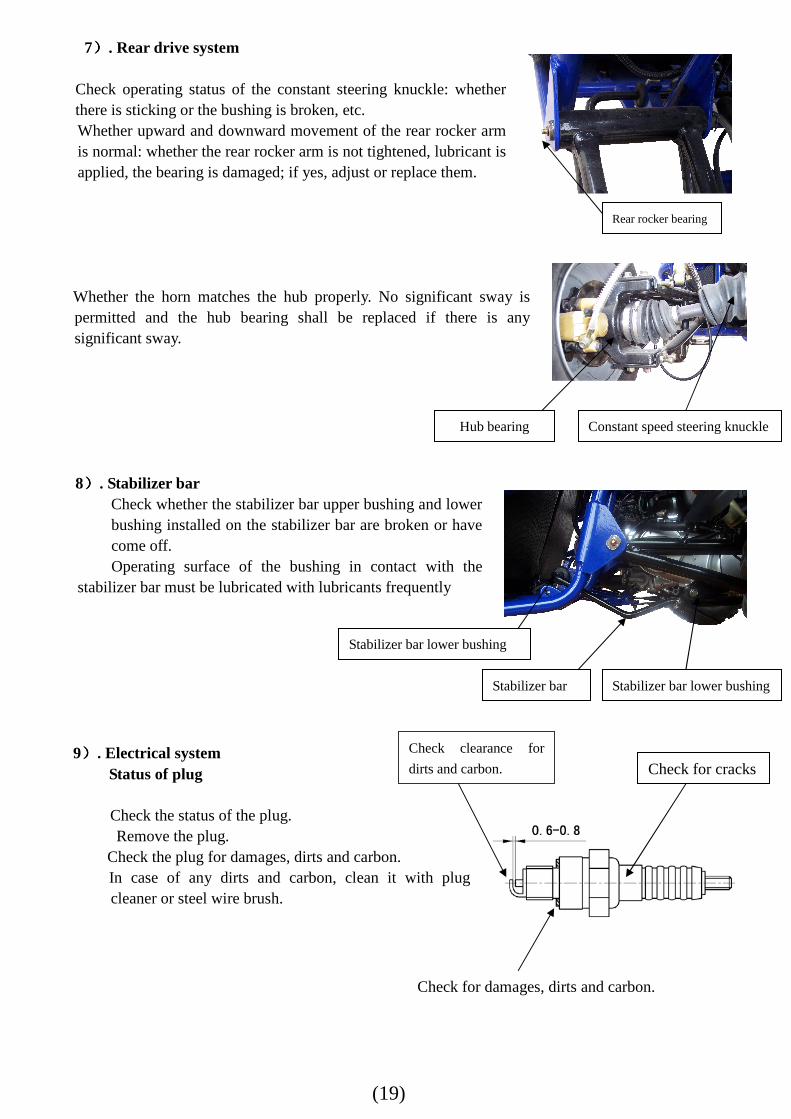
7)))). Rear drive system
Check operating status of the constant steering knuckle: whether there is sticking or the bushing is broken, etc. Whether upward and downward movement of the rear rocker arm is normal: whether the rear rocker arm is not tightened, lubricant is applied, the bearing is damaged; if yes, adjust or replace them. Whether the horn matches the hub properly. No significant sway is permitted and the hub bearing shall be replaced if there is any significant sway. 8)))). Stabilizer bar
Check whether the stabilizer bar upper bushing and lower bushing installed on the stabilizer bar are broken or have come off. Operating surface of the bushing in contact with the
stabilizer bar must be lubricated with lubricants frequently
9)))). Electrical system
Status of plug Check the status of the plug. Remove the plug.
Check the plug for damages, dirts and carbon. In case of any dirts and carbon, clean it with plug cleaner or steel wire brush.
Constant speed steering knuckle
Stabilizer bar lower bushing Stabilizer bar
Check clearance for
dirts and carbon.
Hub bearing
Check for cracks
Check for damages, dirts and carbon.
Rear rocker bearing
Stabilizer bar lower bushing
(20)
Plug Clearance of the plug shall be adjusted to be between 0.6mm~0.8mm。
Ignition timing
Remove the timing hood Confirm ignition timing with timing light.
At idle speed(1500±100rpm), it is normal if it matches the alignment mark “F” well
Function of the ignition advance angle system.
When the function of ignition advance angle system is identical to that of inspection ignition timing, install the timing light.
Then, accelerate the speed of the engine. If at the speed of 7500~8000rpm, the
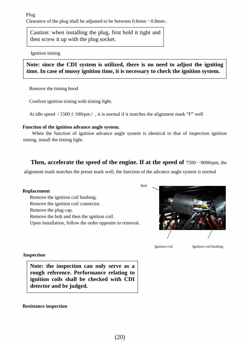
alignment mark matches the preset mark well, the function of the advance angle system is normal Replacement
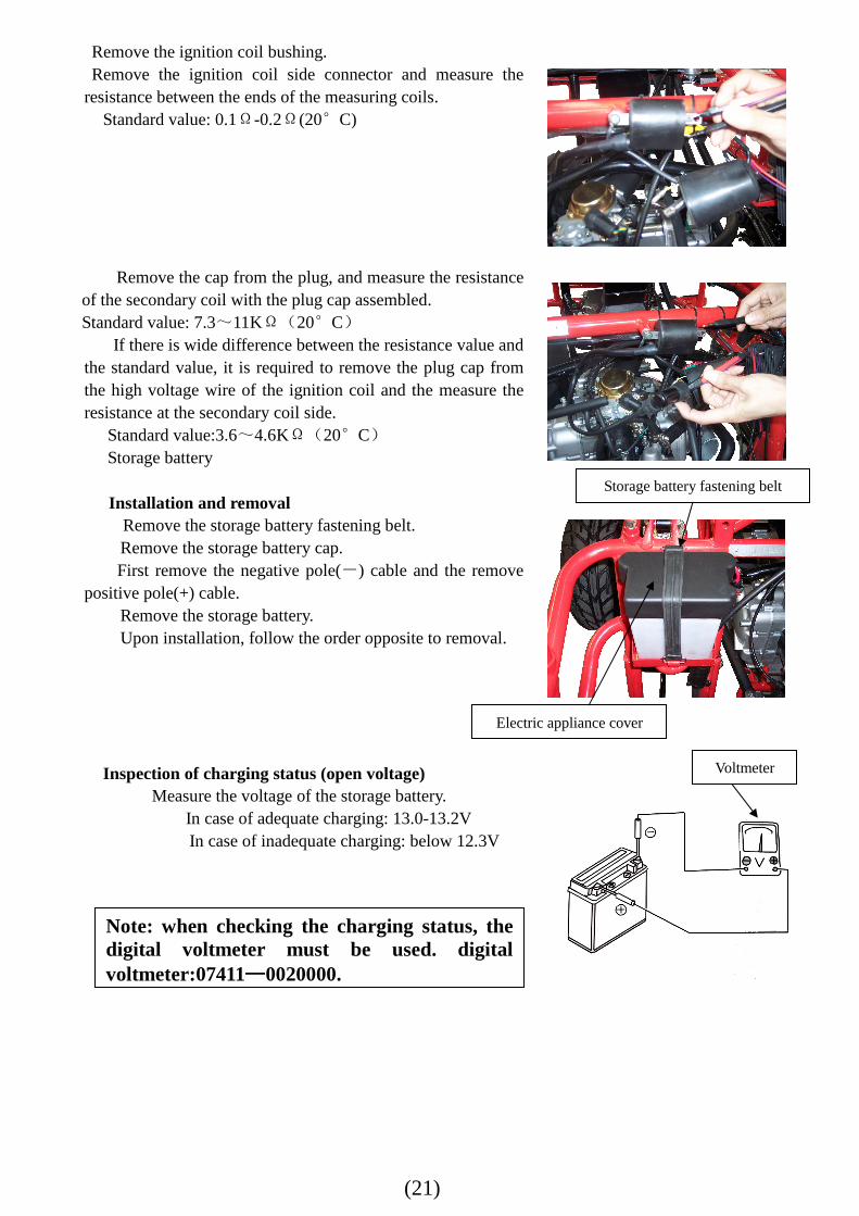
Remove the ignition coil bushing. Remove the ignition coil connector. Remove the plug cap. Remove the bolt and then the ignition coil. Upon installation, follow the order opposite to removal.
Inspection
Resistance inspection
Caution: when installing the plug, first hold it tight and then screw it up with the plug socket.
Note: since the CDI system is utilized, there is no need to adjust the igniting time. In case of mussy ignition time, it is necessary to check the ignition system.
Note: the inspection can only serve as a rough reference. Performance relating to ignition coils shall be checked with CDI detector and be judged.
Ignition coil
Bolt
Ignition coil bushing
(21)
Remove the ignition coil bushing. Remove the ignition coil side connector and measure the
resistance between the ends of the measuring coils. Standard value: 0.1Ω-0.2Ω(20°C)
Remove the cap from the plug, and measure the resistance of the secondary coil with the plug cap assembled. Standard value: 7.3~11KΩ(20°C)
If there is wide difference between the resistance value and the standard value, it is required to remove the plug cap from the high voltage wire of the ignition coil and the measure the resistance at the secondary coil side.
Standard value:3.6~4.6KΩ(20°C) Storage battery
Installation and removal Remove the storage battery fastening belt.
Remove the storage battery cap. First remove the negative pole(-) cable and the remove
positive pole(+) cable. Remove the storage battery. Upon installation, follow the order opposite to removal.
Inspection of charging status (open voltage) Measure the voltage of the storage battery.
In case of adequate charging: 13.0-13.2V In case of inadequate charging: below 12.3V
Note: when checking the charging status, the digital voltmeter must be used. digital voltmeter:07411————0020000.
Voltmeter
Storage battery fastening belt
Electric appliance cover
(22)
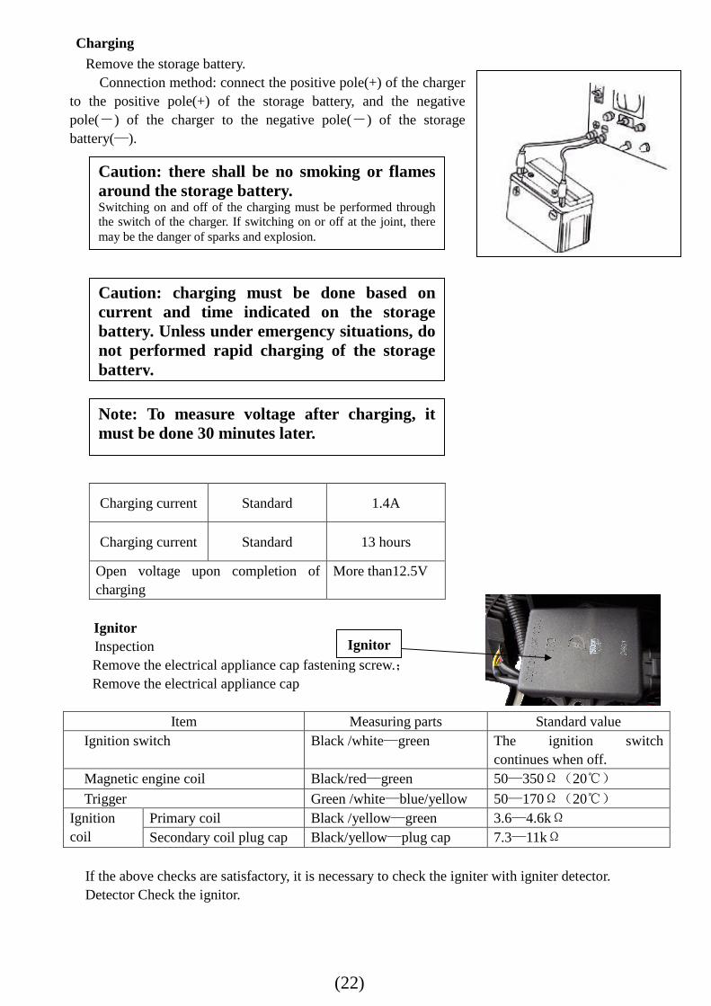
Charging Remove the storage battery.
Connection method: connect the positive pole(+) of the charger to the positive pole(+) of the storage battery, and the negative pole(-) of the charger to the negative pole(-) of the storage battery(—).
Charging current Standard 1.4A
Charging current Standard 13 hours
Open voltage upon completion of charging
More than12.5V
Ignitor Inspection
Remove the electrical appliance cap fastening screw.; Remove the electrical appliance cap
Item Measuring parts Standard value Ignition switch Black /white—green The ignition switch
continues when off. Magnetic engine coil Black/red—green 50—350Ω(20℃)
Trigger Green /white—blue/yellow 50—170Ω(20℃) Ignition coil
Primary coil Black /yellow—green 3.6—4.6kΩ Secondary coil plug cap Black/yellow—plug cap 7.3—11kΩ
If the above checks are satisfactory, it is necessary to check the igniter with igniter detector. Detector Check the ignitor.
Caution: there shall be no smoking or flames around the storage battery. Switching on and off of the charging must be performed through the switch of the charger. If switching on or off at the joint, there may be the danger of sparks and explosion.
Caution: charging must be done based on current and time indicated on the storage battery. Unless under emergency situations, do not performed rapid charging of the storage battery.
Note: To measure voltage after charging, it must be done 30 minutes later.
Ignitor
(23)
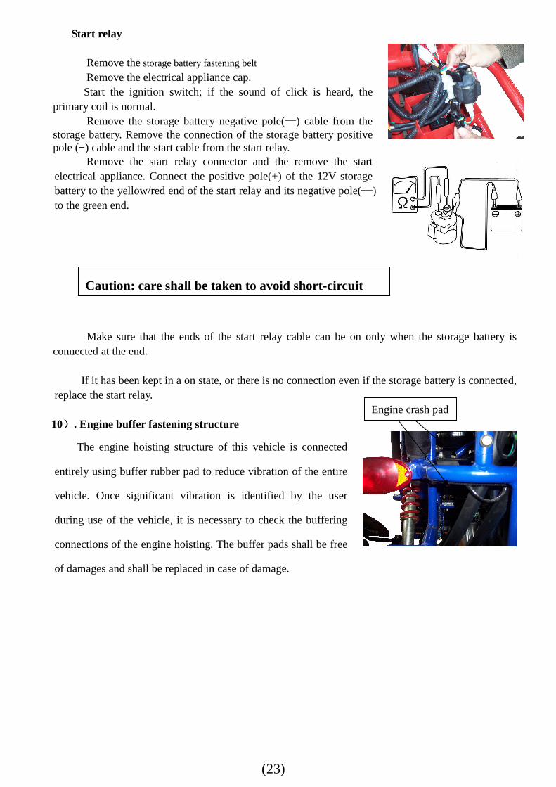
Start relay Remove the storage battery fastening belt Remove the electrical appliance cap. Start the ignition switch; if the sound of click is heard, the
primary coil is normal. Remove the storage battery negative pole(—) cable from the
storage battery. Remove the connection of the storage battery positive pole (+) cable and the start cable from the start relay.
Remove the start relay connector and the remove the start electrical appliance. Connect the positive pole(+) of the 12V storage battery to the yellow/red end of the start relay and its negative pole(—) to the green end.
Make sure that the ends of the start relay cable can be on only when the storage battery is
connected at the end.
If it has been kept in a on state, or there is no connection even if the storage battery is connected, replace the start relay.
10)))). Engine buffer fastening structure
The engine hoisting structure of this vehicle is connected
entirely using buffer rubber pad to reduce vibration of the entire
vehicle. Once significant vibration is identified by the user
during use of the vehicle, it is necessary to check the buffering
connections of the engine hoisting. The buffer pads shall be free
of damages and shall be replaced in case of damage.
Caution: care shall be taken to avoid short-circuit
Engine crash pad
(24)
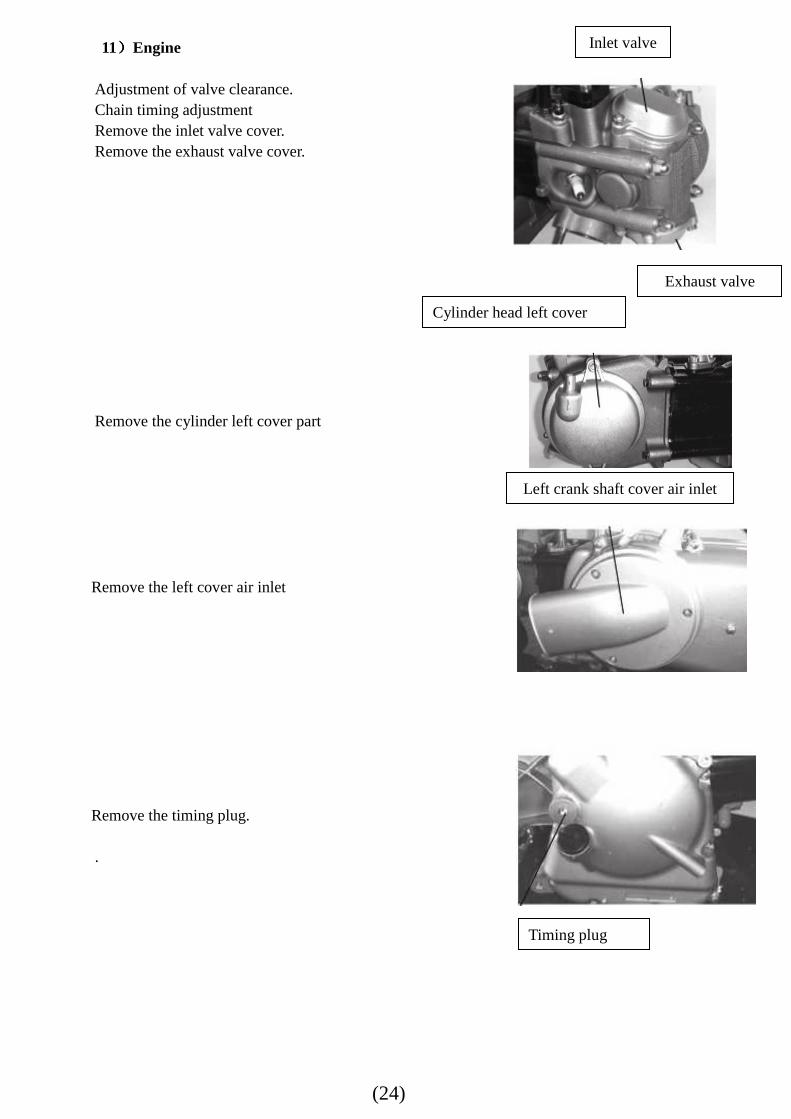
11))))Engine Adjustment of valve clearance. Chain timing adjustment Remove the inlet valve cover. Remove the exhaust valve cover.
Remove the cylinder left cover part Remove the left cover air inlet Remove the timing plug. .
Inlet valve
Exhaust valve
Cylinder head left cover
Left crank shaft cover air inlet
Timing plug
(25)
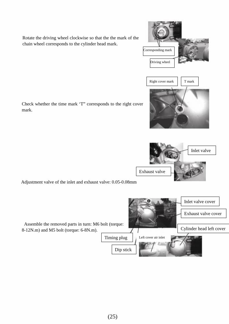
Rotate the driving wheel clockwise so that the the mark of the chain wheel corresponds to the cylinder head mark.
Check whether the time mark ‘T” corresponds to the right cover mark.
Adjustment valve of the inlet and exhaust valve: 0.05-0.08mm
Assemble the removed parts in turn: M6 bolt (torque:
8-12N.m) and M5 bolt (torque: 6-8N.m).
Driving wheel
T mark Right cover mark
Exhaust valve
Inlet valve
Dip stick
Timing plug
Cylinder head left cover
Inlet valve cover
Exhaust valve cover
Left cover air inlet
Corresponding mark
(26)
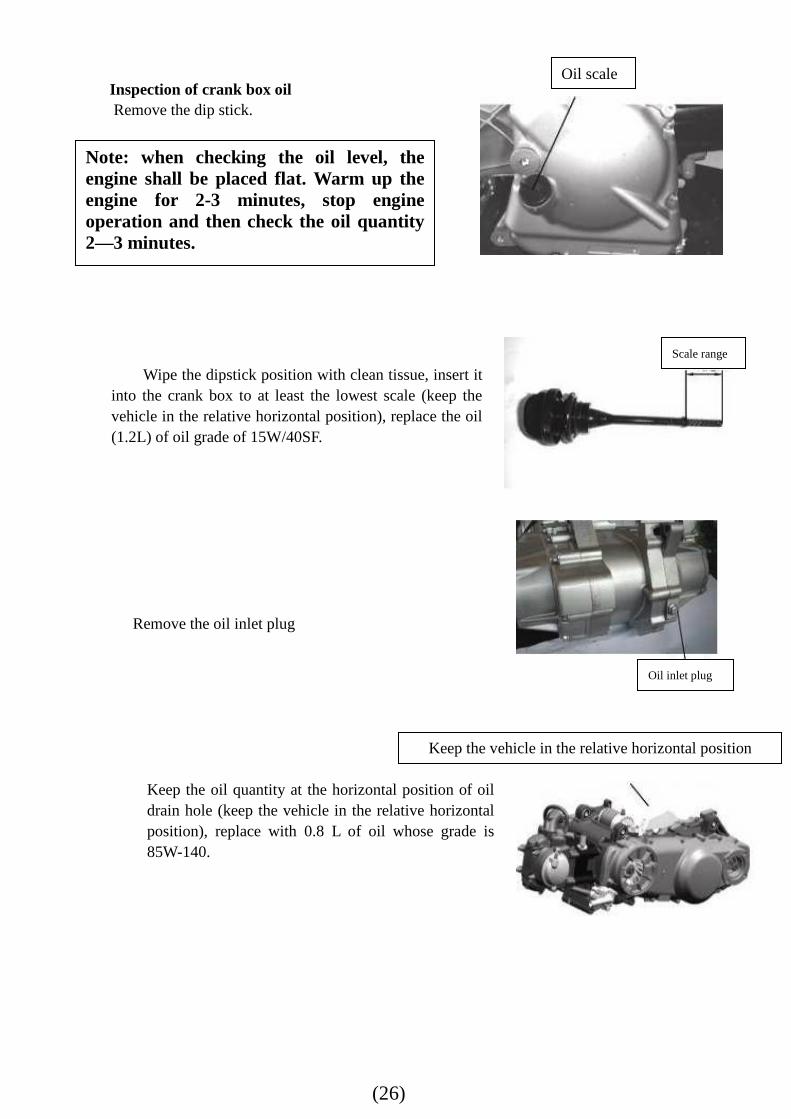
Inspection of crank box oil Remove the dip stick.
Wipe the dipstick position with clean tissue, insert it into the crank box to at least the lowest scale (keep the vehicle in the relative horizontal position), replace the oil (1.2L) of oil grade of 15W/40SF.
Remove the oil inlet plug
Keep the oil quantity at the horizontal position of oil drain hole (keep the vehicle in the relative horizontal position), replace with 0.8 L of oil whose grade is 85W-140.
Keep the vehicle in the relative horizontal position
Note: when checking the oil level, the engine shall be placed flat. Warm up the engine for 2-3 minutes, stop engine operation and then check the oil quantity 2—3 minutes.
Oil scale
Scale range
Oil inlet plug
(27)
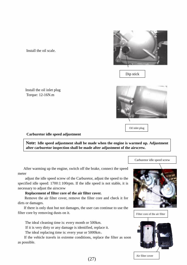
Install the oil scale.
Install the oil inlet plug Torque: 12-16N.m
Carburetor idle speed adjustment
After warming up the engine, switch off the brake, connect the speed
meter adjust the idle speed screw of the Carburetor, adjust the speed to the
specified idle speed: 1700±100rpm. If the idle speed is not stable, it is necessary to adjust the airscrew
Replacement of filter core of the air filter cover. Remove the air filter cover, remove the filter core and check it for
dirts or damages. If there is only dust but not damages, the user can continue to use the
filter core by removing dusts on it. The ideal cleaning time is: every month or 500km. If it is very dirty or any damage is identified, replace it. The ideal replacing time is: every year or 5000km。 If the vehicle travels in extreme conditions, replace the filter as soon
as possible.
Dip stick
Oil inlet plug
Note: Idle speed adjustment shall be made when the engine is warmed up. Adjustment after carburetor inspection shall be made after adjustment of the airscrew.
Carburetor idle speed screw
Filter core of the air filter
Air filter cover
(28)
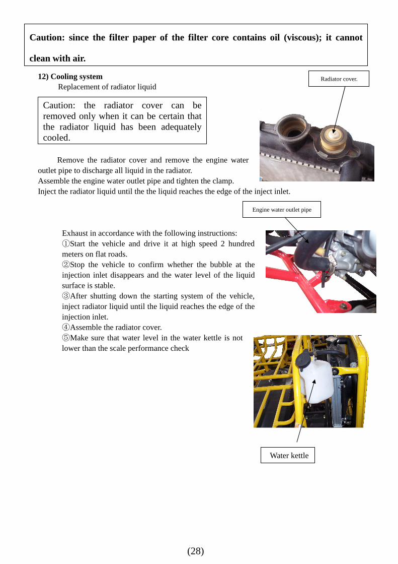
12) Cooling system
Replacement of radiator liquid
Remove the radiator cover and remove the engine water
outlet pipe to discharge all liquid in the radiator. Assemble the engine water outlet pipe and tighten the clamp. Inject the radiator liquid until the the liquid reaches the edge of the inject inlet.
Exhaust in accordance with the following instructions: ①Start the vehicle and drive it at high speed 2 hundred meters on flat roads. ②Stop the vehicle to confirm whether the bubble at the injection inlet disappears and the water level of the liquid surface is stable. ③After shutting down the starting system of the vehicle, inject radiator liquid until the liquid reaches the edge of the injection inlet. ④Assemble the radiator cover. ⑤Make sure that water level in the water kettle is not lower than the scale performance check
Caution: the radiator cover can be removed only when it can be certain that the radiator liquid has been adequately cooled.
Radiator cover.
Engine water outlet pipe
Water kettle
Caution: since the filter paper of the filter core contains oil (viscous); it cannot
clean with air.
(29)
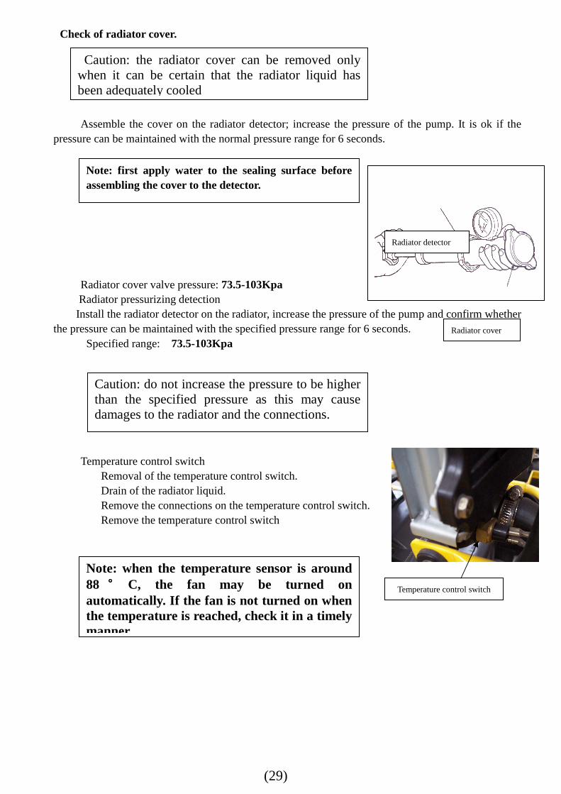
Check of radiator cover.
Assemble the cover on the radiator detector; increase the pressure of the pump. It is ok if the
pressure can be maintained with the normal pressure range for 6 seconds.
Radiator cover valve pressure: 73.5-103Kpa Radiator pressurizing detection Install the radiator detector on the radiator, increase the pressure of the pump and confirm whether
the pressure can be maintained with the specified pressure range for 6 seconds. Specified range: 73.5-103Kpa
Temperature control switch
Removal of the temperature control switch. Drain of the radiator liquid. Remove the connections on the temperature control switch. Remove the temperature control switch
Caution: the radiator cover can be removed only when it can be certain that the radiator liquid has been adequately cooled
Note: first apply water to the sealing surface before assembling the cover to the detector.
Caution: do not increase the pressure to be higher than the specified pressure as this may cause damages to the radiator and the connections.
Note: when the temperature sensor is around 88 °°°° C, the fan may be turned on automatically. If the fan is not turned on when the temperature is reached, check it in a timely manner.
Temperature control switch
Radiator detector
Radiator cover