Passive Design Features for Energy-Efficient Residential Buildings in Tropical Climates

Chiller Plants for Tropical Climates Today’s Agenda Chiller developments VSD advantages YMC2 Technology Chiller plant optimization Series counter-flow configuration Opportunities from ‘de-coupling’ Multi CHW loop applications Efficiency possibilities Example project
YMC2 – YORK® State of the Art Magnetic Centrifugal Chillers
AIRAH 2014

L1
L2
L3 Control electronics
Control, monitor, and communication
Motor
M3
U1
V1
W
Rectifier Inverter DC L
C U V1 V3 V5
V4 V6 V2
In recent decades, significant gains in chiller efficiency at full & part load through advances in HX, compressor, motor, driveline, and economizers.
The biggest single efficiency gain has been at reduced ‘lift’ condition with the adoption of the variable speed drive.
YK YMC2
YMC2 – YORK® State of the Art Magnetic Centrifugal Chillers
Despite using more environmentally benign, yet less efficient refrigerants, chiller efficiency has improved significantly

Reduces inrush current to < than FL amps (soft start)
Corrects power factor close to unity
Reduces utility demand
Regulates compressor speed to provide the most efficient chiller operation, reducing energy consumption
YMC2 – YORK® State of the Art Magnetic Centrifugal Chillers
VSD technology benefits

High efficiency permanent magnet motor
Latest Generation VSD
Frictionless magnetic bearings
Direct drive compressor
Oil free design
YMC2 – YORK® State of the Art Magnetic Centrifugal Chillers
Recent technology introduction Variable speed magnetic bearing oil free centrifugal chillers

Load% LWT EWT COP EWT COP COP COP % % 100 6.7 29.4 6.46 29.4 6.46 6.28 6.60 2.1 5.0 90 6.7 29.4 6.54 27.2 7.05 7.05 7.43 5.6 5.6 80 6.7 29.4 6.52 25.0 7.55 7.99 8.41 11.5 5.5 70 6.7 29.4 6.44 22.8 7.83 9.09 9.66 22.8 6.2 60 6.7 29.4 6.25 20.5 8.12 10.34 11.23 38.6 9.0 50 6.7 29.4 6.14 18.3 8.18 11.72 13.12 61.1 13.0 40 6.7 29.4 5.75 18.3 7.55 11.31 12.79 89.5 13.0 30 6.7 29.4 5.28 18.3 6.77 10.34 11.96 76.1 15.7 20 6.7 29.4 4.46 18.3 5.55 9.30 10.31 85.9 10.9 15 6.7 29.4 3.96 18.3 4.88 8.25 8.60 75.7 4.0
At AHRI “relief “ conditions At constant conditions
YK VSD
YK CSD
YMC2
VSD YK
CSD YMC2
VS YK CSD
YMC2
VS YK VSD
YMC2 – YORK® State of the Art Magnetic Centrifugal Chillers
Comparing fixed speed to variable speed technology

4.0
5.0
6.0
7.0
8.0
9.0
10.0
11.0
12.0
13.0
14.0
10 20 30 40 50 60 70 80 90 100
CO
P
% Capacity
YK CSD Constant CEFT YK CSD AHRI Relief YK VSD AHRI Relief YMC2 AHRI Relief
Chillers operate for 85% of the time within this capacity range
YMC2 – YORK® State of the Art Magnetic Centrifugal Chillers
VSD chillers perform best with condenser water “relief”

How to effectively apply high efficiency VSD chillers to HVAC systems
in tropical climates?
YMC2 – YORK® State of the Art Magnetic Centrifugal Chillers
Design Performance
Chiller58%
Tower5%
Fans24%
Pumps13%
One of the most ‘constant’ tropical climates is Singapore. What levels of plant efficiency can be achieved where operating conditions have limited variance ?

Measure & Verify
Optimize System
Automate System
Apply components effectively, optimally
Select components effectively, optimally
Design system infrastructure to maximize efficiency potential
Operating Decisions
Design Decisions
Maintain
Efficient chillers are a great foundation, but optimization is a process
YMC2 – YORK® State of the Art Magnetic Centrifugal Chillers

Apply variable speed drives Chillers Pumps Tower Fans Reduce “lift” lower CW temperatures higher CHW temperatures Reduce pump energy wide delta T variable flow Efficient chiller staging energy based vs load based
The key functional components of chiller plant optimization are the same irrespective of jobsite location
YMC2 – YORK® State of the Art Magnetic Centrifugal Chillers

Lower tower water temps
Higher chilled water temps
Limited opportunity at design condition. Some opportunity when at off-design.
Significant opportunity with HT CHW, chiller arrangement,and airside design
AND
YMC2 – YORK® State of the Art Magnetic Centrifugal Chillers
All chillers benefit from reduced “lift”…..especially VSD chillers. How to achieve reduced ‘lift’ in tropical climates ?

Supply
L1
L2
L3
Control electronics
Control, monitor, and communication
Motor
M3
U1
V1
W
Rectifier Inverter DC L
C U V1 V3 V5
V4 V6 V2
Johnson Controls - Proprietary & Confidential
Every 1 deg C of ‘lift’ reduction improves VSD chiller efficiency by 3-6%
depending on the technology
YMC2 – YORK® State of the Art Magnetic Centrifugal Chillers
One has to ‘create’ the optimum operating environment
Every 1 deg C counts !

Conventional design @ “ASIA” conditions
Pressure
Enthalpy
Lift
12° C 6° C
32 ° C 95° F 35° C
37° C
YMC2 – YORK® State of the Art Magnetic Centrifugal Chillers

The cooling tower is the most effective heat transfer device in the system
32 - 37 deg C OR 30 - 35 deg C
Design Condition
Can we lower tower water temps ?
Tower water does not have to be held constant
Energy efficiency ratio = 7.5 kW / 875 kWr = 117
250 ton tower super low noise tower
Conventional design = approach 5-7 deg C Optimized design = approach 3-4 deg C
YMC2 – YORK® State of the Art Magnetic Centrifugal Chillers

Singapore Building Operation Profiles can take some advantage of ambient wet bulb relief
Source: ASHRAE IWEC Weather Bin Data
Singapore tower water will achieve 3 deg C of relief with 5 deg C of relief available for 24/7 systems
ASHRAE 32.8db / 27.3wb
YMC2 – YORK® State of the Art Magnetic Centrifugal Chillers
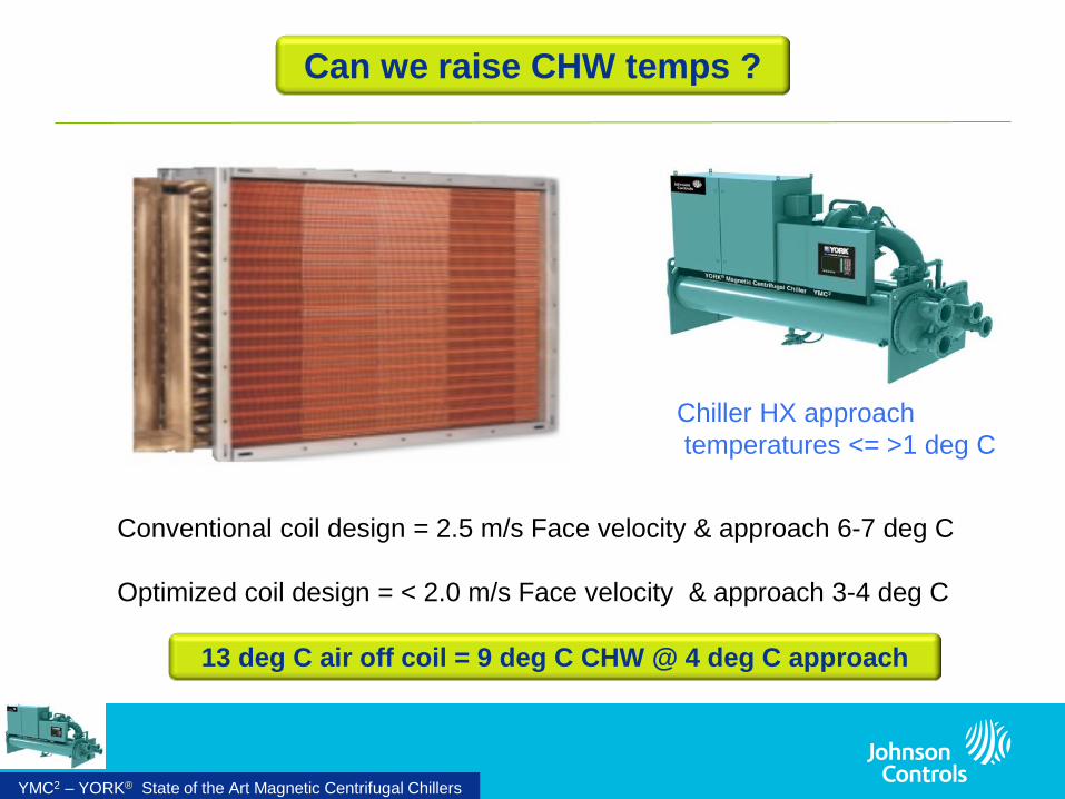
Can we raise CHW temps ?
Conventional coil design = 2.5 m/s Face velocity & approach 6-7 deg C Optimized coil design = < 2.0 m/s Face velocity & approach 3-4 deg C
Chiller HX approach temperatures <= >1 deg C
YMC2 – YORK® State of the Art Magnetic Centrifugal Chillers
13 deg C air off coil = 9 deg C CHW @ 4 deg C approach

Design delta T 5.5C 7.5C 9.5C % Flow reduction 0 2/7.5 =27% 4/9.5 = 42%
Wide delta T chilled water systems save significant pump energy, but to use ‘similar’ CHW coils, the chillers must work harder.
12.5 / 7.0 deg C
13.5 / 6.0 deg C
14.5 / 5.0 deg C
YMC2 – YORK® State of the Art Magnetic Centrifugal Chillers
Can we widen the CHW temperature range to 8-10 deg C?
Using 9 deg C CHW & 10 deg C delta T will need different AHU CHW coils
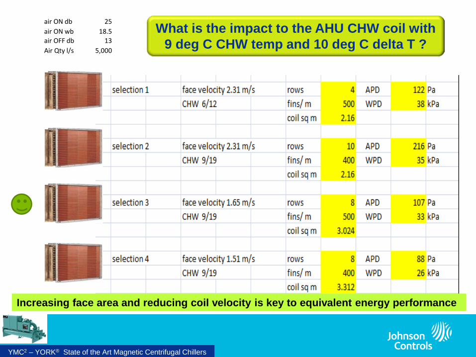
air ON db 25 air ON wb 18.5 air OFF db 13 Air Qty l/s 5,000
Increasing face area and reducing coil velocity is key to equivalent energy performance
YMC2 – YORK® State of the Art Magnetic Centrifugal Chillers
What is the impact to the AHU CHW coil with 9 deg C CHW temp and 10 deg C delta T ?

Smaller CHW pipes
Smaller CHW valves and fittings
Reduced thermal insulation area
Smaller CHW pumps, motor kW, and VSD’s
Smaller CHW pump electrical requirements
Smaller chiller electrical requirements
1st cost economics of a 9 /19 deg C CHW system
Savings Costs Larger AHU coil HX areas and
rows to achieve equivalent energy performance
If the additional coil area cannot be accommodated in AHU height, the AHU footprint will increase
YMC2 – YORK® State of the Art Magnetic Centrifugal Chillers

9 deg C 14.0 deg C 19 deg C
30 deg C 32.5 deg C 35 deg C
Lift is reduced 2.5 degrees C Lift is reduced 5.0 degrees C
VPF
VPF = variable primary CHW flow & fixed delta T
Wide CHW delta T best suits Series Counter-flow chillers
YMC2 – YORK® State of the Art Magnetic Centrifugal Chillers
Series Counter-Flow chillers further reduce lift

9 14 19
30 32.5 35
Series counter flow YMC2 performance at Singapore conditions (office hours)
1645 kWr 1520kWr
Load% CHW in CHWint CHWout CWin CWint CWout UP
COP DN
COP SYS COP
100 19 13.8 9 30 32.4 35 8.75 7.83 8.29
90 19 13.8 9 29.4 31.6 33.9 9.33 8.14 8.70
80 19 13.8 9 28.8 30.7 32.8 9.96 8.49 9.20
70 19 13.8 9 28.2 29.9 31.7 10.56 8.79 9.63
60 19 13.8 9 27.6 29.1 30.7 10.95 8.92 9.88
50 19 13.8 9 27 28.2 29.5 11.42 8.92 10.07
40 19 13.8 9 27 28 29.1 10.95 8.43 9.58
30 18.5 13.6 9 27 27.7 28.5 10.02 7.46 8.60
20 15.4 12.1 9 27 27.5 28.1 6.83 5.38 6.04
YMC2 – YORK® State of the Art Magnetic Centrifugal Chillers
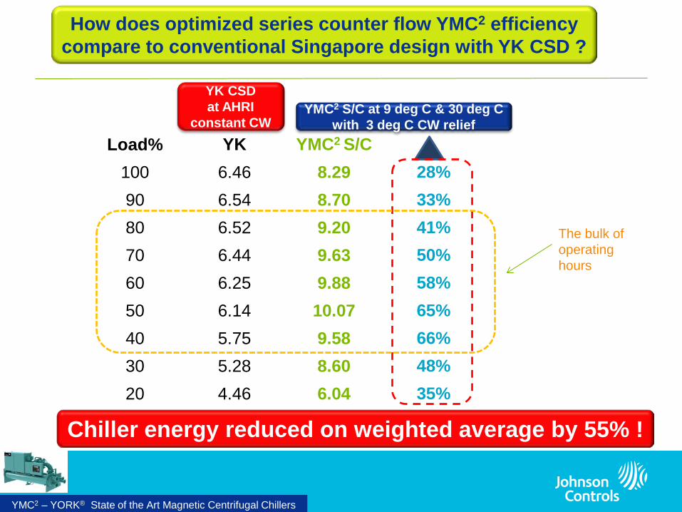
Load% YK YMC2 S/C 100 6.46 8.29 28% 90 6.54 8.70 33% 80 6.52 9.20 41% 70 6.44 9.63 50% 60 6.25 9.88 58% 50 6.14 10.07 65% 40 5.75 9.58 66% 30 5.28 8.60 48% 20 4.46 6.04 35%
YK CSD at AHRI
constant CW YMC2 S/C at 9 deg C & 30 deg C
with 3 deg C CW relief
YMC2 – YORK® State of the Art Magnetic Centrifugal Chillers
How does optimized series counter flow YMC2 efficiency compare to conventional Singapore design with YK CSD ?
Chiller energy reduced on weighted average by 55% !
The bulk of operating hours

4.0
5.0
6.0
7.0
8.0
9.0
10.0
11.0
12.0
10 20 30 40 50 60 70 80 90 100
CO
P
% Capacity
YK CSD Constant CEFT YMC2 SCF Office
YMC2 – YORK® State of the Art Magnetic Centrifugal Chillers
How has performance improved over conventional design ?

Compared to constant speed chillers
at AHRI constant condenser water
conditions
CHW pump energy savings 35 %
YMC2 S/C chillers 28-66 % more efficient
Energy economics of a 9 /19 deg C S/C CHW system
Savings Costs Marginally higher design flow
pump pressures with series HX
Note : pressures are reduced at . . part load with variable flow
Marginally greater tower fan energy to leverage the 3 deg C reduction in CW temperature
Note: tower efficiency is an order of magnitude greater than chillers
YMC2 S/C chillers 28% more efficient at design
YMC2 S/C chillers up to 66% more efficient at reduced load & lift YMC2 S/C chillers 55% more efficient on weighted average
YMC2 – YORK® State of the Art Magnetic Centrifugal Chillers

19 C
9 C 14 C
HT CHW loop
VPF
Typical system = CHW VAV AHU’s
YMC2 – YORK® State of the Art Magnetic Centrifugal Chillers

Are there more efficiency gains to be found ? Can we go higher than 9 deg C CHW ?
YMC2 – YORK® State of the Art Magnetic Centrifugal Chillers

The most efficient HVAC systems treat the latent loads separately “De-coupling”
Cooling Load Component Latent Sensible
Conduction thru walls, roof etc
Solar radiation
Lights
People
Equipment (some…most is sensible)
Infiltration
Ventilation
System heat gains
YMC2 – YORK® State of the Art Magnetic Centrifugal Chillers

Typically @ 14 degrees C CHW
One HVAC system performs all dehumidification
One HVAC system performs only sensible cooling
De-coupled
A typical application that de-couples loads is a chilled beam system
YMC2 – YORK® State of the Art Magnetic Centrifugal Chillers
DOAS
+ Chilled Beam
Typically @ 6 degrees C CHW

16 C
6 C 11 C
LT CHW loop (S/C chillers)
VPF VPF 18 C
14.0 C
ACB HT CHW loop
Plant room Plant room
DOAS supplies dry cool primary O/A to the active chilled beams
YMC2 – YORK® State of the Art Magnetic Centrifugal Chillers
What can a CHW system look like for a chilled beam application ?

16 C
6 C 11 C
LT CHW loop (S/C chillers)
VPF
Plant room
VPF 18 C
14.0 C
ACB HT CHW loop
Plant room
DOAS with cascade reduction in primary air temp
YMC2 – YORK® State of the Art Magnetic Centrifugal Chillers
Efficiency is improved further where a % of O/A load is removed by the HT loop

19 C
9 C 14 C
VAV AHU(s)
CHW loop
VPF
DOAS pre-conditions the O/A supplied to the zone VAV AHU’s
With a VAV system space dew point control is not as critical.
VPF 19 C
14 C
YMC2 – YORK® State of the Art Magnetic Centrifugal Chillers
Similar methodology applied to a VAV system

Load% YK YMC2 s/c YMC2 100 6.46 8.29 28% 9.20 90 6.54 8.70 33% 9.77 80 6.52 9.20 41% 10.37 70 6.44 9.63 50% 10.95 60 6.25 9.88 58% 11.38 50 6.14 10.07 65% 11.68 40 5.75 9.58 66% 11.20 30 5.28 8.60 48% 10.34 20 4.46 6.04 35% 8.45
Office profile
HT YMC2 delivers weighted average 79% improvement over base design
YK CSD at AHRI
constant CW
YMC2 S/C at 9 deg C YMC2 at 14 deg C
42% 49% 59% 70% 82% 90% 95% 95% 89%
Office profile
YMC2 – YORK® State of the Art Magnetic Centrifugal Chillers
What efficiency levels can the HT loop chiller deliver ?

4.0
5.0
6.0
7.0
8.0
9.0
10.0
11.0
12.0
10 20 30 40 50 60 70 80 90 100
CO
P
% Capacity
YK CSD Constant CEFT YMC2 Evap 14/18C YMC2 SCF Office
YMC2 – YORK® State of the Art Magnetic Centrifugal Chillers
With dual loops, plant performance can be further improved
Where 30 % load is transferred to the HT loop , cooling efficiency is improved a further 8%

Example of Dual CHW loop project
YMC2 – YORK® State of the Art Magnetic Centrifugal Chillers
JEM Project Singapore
Multi stage
fresh air treatment
Dual CHW
loops
Elevated CHW temps
Series
counter-flow LT chillers
Wide delta T
LT loop

Greenmark ‘Platinum’ rating @ 0.55 kW/Ton = 6.4 plant COP
Low temp loop = 9/18 deg C with 2 S/C York YK CSD chiller pairs
High temp loop = 15/20 deg C with 2 x York YK VSD chillers
YMC2 – YORK® State of the Art Magnetic Centrifugal Chillers

0.0%
5.0%
10.0%
15.0%
20.0%
25.0%
30.0%
24-26 22-24 20-22 18-20 16-18 < 16
% O
pera
tion
Hou
rs
Wet-bulb Temperature oC
Source : YorkCalc Energy Analysis Database
YMC2 – YORK® State of the Art Magnetic Centrifugal Chillers
66% hrs
Cairns has a greater potential for condenser water relief
Cairns 24Hrs Weather Bin Profile
What about Australia ?
Johnson Controls PowerPoint Guidelines | February 8, 2008 36
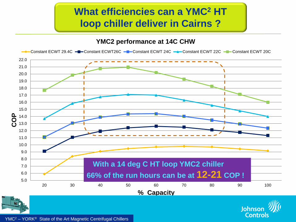
5.0
6.0
7.0
8.0
9.0
10.0
11.0
12.0
13.0
14.0
15.0
16.0
17.0
18.0
19.0
20.0
21.0
22.0
20 30 40 50 60 70 80 90 100
CO
P
% Capacity
YMC2 performance at 14C CHW Constant ECWT 29.4C Constant ECWT26C Constant ECWT 24C Constant ECWT 22C Constant ECWT 20C
YMC2 – YORK® State of the Art Magnetic Centrifugal Chillers
With a 14 deg C HT loop YMC2 chiller 66% of the run hours can be at 12-21 COP !
What efficiencies can a YMC2 HT loop chiller deliver in Cairns ?
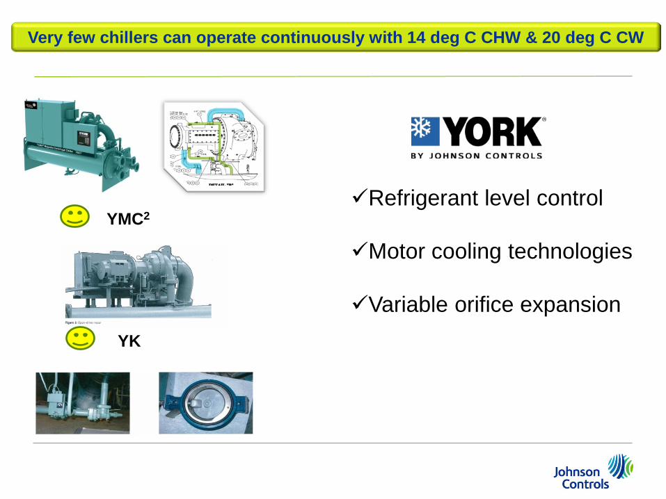
Very few chillers can operate continuously with 14 deg C CHW & 20 deg C CW
YMC2
YK
Refrigerant level control Motor cooling technologies
Variable orifice expansion

High Efficiency VSD or VSD magnetic bearing chillers
Raise CHW supply temperatures
Wide delta T CHW with series counter-flow chiller arrangement
Re-evaluate design approach temperatures
cooling towers are efficient and low cost
lower face velocity coils
De-couple and condition outside air loads separately
Dual HT & LT CHW loops with cascade coils & ‘low lift’ VSD chillers
For Consideration
YMC2 – YORK® State of the Art Magnetic Centrifugal Chillers

The innovation requirements of green buildings challenge traditional paradigms
Smart Green Integrated Sustainable Solutions
YMC2 – YORK® State of the Art Magnetic Centrifugal Chillers