Chemical Cleaning İn Line • Health & Safety • Diagnostic ... · PDF fileParker...
27
STEEL MAKING PROCESS CASTING TECHNOLOGY PROCESS ROLLING PROCESS REHEATING PROCESS PLANT REVAMPING AND NEW INSTALLATIONS Y o u r g l o b a l l y h y d r a u l i c p a r t n e r f o r s t e e l p r o c e s s www.completehydraulicsolutions.com PICKLING FLUSHING PIPING 12 th Internaonal Non-Ferrous Metals Technology, Machinery And Products Trade Fair 29 September – 01 October 2016 / İSTANBUL-TURKEY H8 D105
Transcript of Chemical Cleaning İn Line • Health & Safety • Diagnostic ... · PDF fileParker...

STEEL MAKING PROCESSCASTING TECHNOLOGY PROCESS
ROLLING PROCESSREHEATING PROCESS
PLANT REVAMPING AND NEW INSTALLATIONS
Your g
loba
lly
hydr
aulic partner for steel process
www.completehydraulicsolutions.com
PICKLING
FLUSHING
PIPING
12th International Non-Ferrous Metals Technology, Machinery And Products Trade Fair
29 September – 01 October 2016 / İSTANBUL-TURKEY
H8D105
www.completehydraulicsolutions.com www.completehydraulicsolutions.com
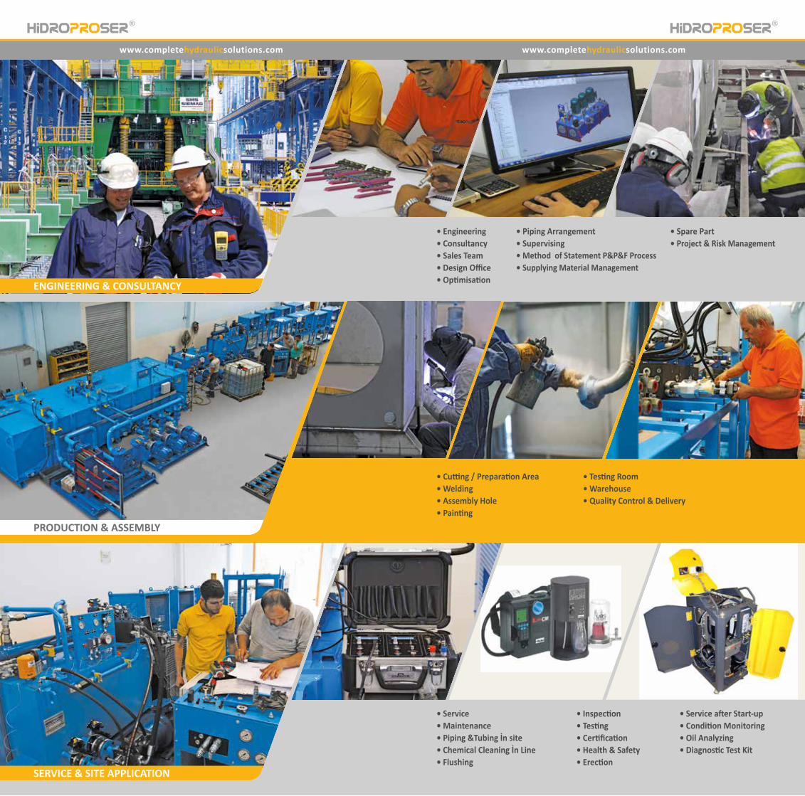
ENGINEERING & CONSULTANCY
PRODUCTION & ASSEMBLY
SERVICE & SITE APPLICATION
• Engineering• Consultancy• Sales Team• Design Office• Optimisation
• Piping Arrangement• Supervising
• Service• Maintenance• Piping &Tubing İn site• Chemical Cleaning İn Line• Flushing
• Cutting / Preparation Area• Welding• Assembly Hole• Painting
• Testing Room• Warehouse• Quality Control & Delivery
• Method of Statement P&P&F Process• Supplying Material Management
• Spare Part• Project & Risk Management
• Inspection• Testing• Certification• Health & Safety• Erection
• Service after Start-up• Condition Monitoring• Oil Analyzing• Diagnostic Test Kit
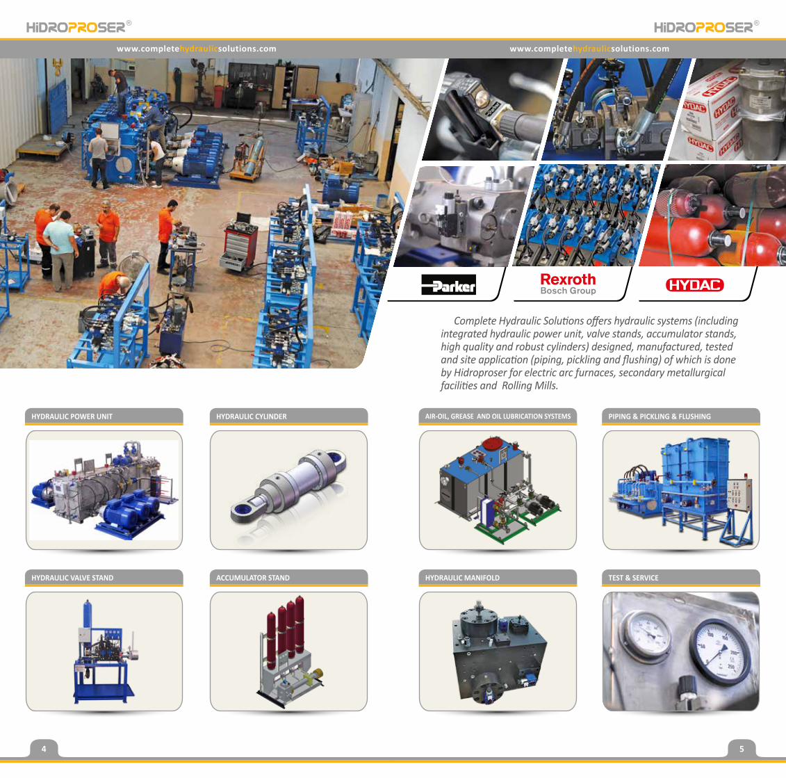
HYDRAULIC POWER UNIT
HYDRAULIC VALVE STAND
HYDRAULIC CYLINDER
ACCUMULATOR STAND HYDRAULIC MANIFOLD
AIR-OIL, GREASE AND OIL LUBRICATION SYSTEMS
TEST & SERVICE
PIPING & PICKLING & FLUSHING
www.completehydraulicsolutions.com www.completehydraulicsolutions.com
Complete Hydraulic Solutions offers hydraulic systems (including integrated hydraulic power unit, valve stands, accumulator stands, high quality and robust cylinders) designed, manufactured, tested and site application (piping, pickling and flushing) of which is done by Hidroproser for electric arc furnaces, secondary metallurgical facilities and Rolling Mills.
4 5
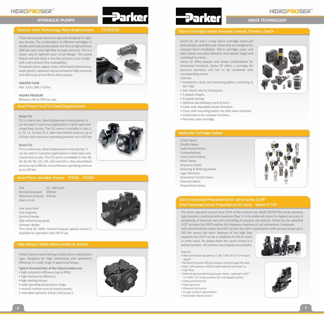
These vane pumps have been specially designed for high/low circuits. The combination of different cartridges in double and triple pumps allows low flow at high pressure (300 bar max.) and high flow at lower pressure. This is a clever way to optimize your circuit design. This pump feature will also allow a very fast pressure cycle changewith a very precise flow repeatability.Phosphate esters, organic esters, chlorinated hydrocarbons, water glycols, rapeseed may be pumped at high pressures and with long service life by these pumps.
GREATER FLOW Size: 5,8 to 268,7 ml/rev.
HIGHER PRESSUREBetween 240 to 300 bar max.
Series CE, CP and C 2-way slip-in cartridge valves are hydraulically controlled seat valves that are designed for compact block installation. Slip-in cartridge, cover, and pilot system are valve elements that permit single and combined functions. Series CE offers poppet and sleeve combinations for directional functions. Series CP offers a cartridge for pressure functions and has to be combined with corresponding covers. Features • Installation cavity and mounting pattern according to
ISO 7368. • One sleeve only for all poppets. • 5 poppet shapes. • 5 poppet springs. • Optional seal between ports B and C. • Cover with adjustable stroke limitation. • Cover with mounting pattern for pilot valve assembly. • Combinations for complex functions. • Normally open cartridge
Check ValvesShuttle ValvesLoad Control ValvesCounterbalanceFlow Control ValvesRelief ValvesSequence ValvesReducing & Relieving ValvesLogic ElementsDirectional Control ValvesSolenoid ValvesProportional Valves
The direct operated control valve D1FP of the nominal size NG06 (CETOP 03) shows extremly high dynamics combined with maximum flow. It is the preferred choice for highest accuracy in positioning of hydraulic axis and controlling of pressure and velocity. Driven by the patented VCD® actuator the D1FP reaches the frequency response of real servovalves. Comparedwith solenoid driven valves the D1FP can also be used in applications with pressure drops up to 350 bar across the valve. Because of the high flow capability the D1FP can be a substitute for NG10 valves in some cases. At power-down the spool moves in a defined position. All common input signals are available.
Features• Real servovalve dynamics (-3 dB / 350 Hz at ±5 % input
signal)• No flow limit up to 350 bar pressure drop through the valve• Max. tank pressure 350 bar (with external drain port y)• High flow• Defined spool positioning at power-down - optional P-A/B-T
or P-B/A-T or center position (for overlapped spools)• Onboard electronics• High dynamics• Onboard electronics• Energy saving A-regeneration• Switchable hybrid version
Series F11F11 is a bent-axis, fixed displacement motor/pump. Itcan be used in numerous applications in both open andclosed loop circuits. The F11 series is available in sizes 5, 6, 10, 12, 14 and 19 cc. Max intermittent pressure up to 420 bar and continuous operating pressure up to 350 bar
Series F12F12 is a bent-axis, fixed displacement motor/pump. Itcan be used in numerous applications in both open andclosed loop circuits. The F12 series is available in sizes 30, 40, 60, 80, 90, 110, 125, 150 and 250 cc. Max intermittent pressure up to 480 bar and continuous operating pressure up to 420 bar
Size 16...360 ccpmNominal pressure 350 barMaximum pressure 420 barOpen circuit
Low noise levelFast responseService-friendlyHigh self-priming speedCompact designThru drive for 100% nominal torqueA special version is available for operation with HFC-fl uid.
Parker Calzoni motors belong to fluid column radial piston type, designed for high mechanical and volumetric efficiency in a wide range of speed and torque.
Typical characteristics of the Calzoni motors are:• high volumetric efficiency (up to 99%);• high mechanical efficiency;• high starting torque;• wide operating temperature range;• smooth rotation even at lowest speeds;• reversible operation (motor and pump );
Denison Vane Technology, fixed displacement T7/T67/T6 Slip-in Cartridge Valves Pressure Control, Throttle, Check
Hydraulic Cartridge Valves
Direct Operated Proportional DC Valve Series D1FPPilot Operated Servo Proportional DC Valve Series D*1FP
Axial Piston F11/F12 Fixed Displacement
Axial Piston Variable Pumps PV016 … PV360
High torque radial piston pumps & motors
VALVE TECHNOLOGYHYDRAULIC PUMPS
6 7
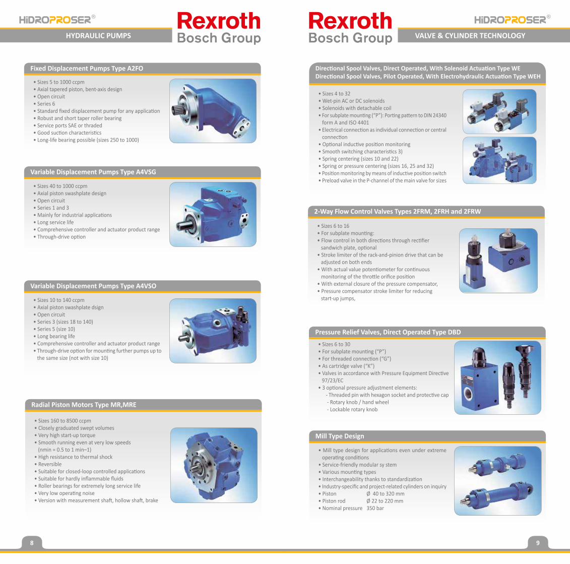
• Sizes 5 to 1000 ccpm• Axial tapered piston, bent-axis design• Open circuit• Series 6• Standard fixed displacement pump for any application• Robust and short taper roller bearing• Service ports SAE or thraded• Good suction characteristics• Long-life bearing possible (sizes 250 to 1000)
• Sizes 4 to 32• Wet-pin AC or DC solenoids• Solenoids with detachable coil• For subplate mounting (“P”): Porting pattern to DIN 24340
form A and ISO 4401• Electrical connection as individual connection or central
connection• Optional inductive position monitoring• Smooth switching characteristics 3)• Spring centering (sizes 10 and 22)• Spring or pressure centering (sizes 16, 25 and 32)• Position monitoring by means of inductive position switch• Preload valve in the P-channel of the main valve for sizes
• Sizes 6 to 30• For subplate mounting (“P”)• For threaded connection (“G”)• As cartridge valve (“K”)• Valves in accordance with Pressure Equipment Directive
97/23/EC• 3 optional pressure adjustment elements: - Threaded pin with hexagon socket and protective cap - Rotary knob / hand wheel - Lockable rotary knob
• Sizes 40 to 1000 ccpm• Axial piston swashplate design• Open circuit• Series 1 and 3• Mainly for industrial applications• Long service life• Comprehensive controller and actuator product range• Through-drive option
• Sizes 10 to 140 ccpm• Axial piston swashplate dsign• Open circuit• Series 3 (sizes 18 to 140)• Series 5 (size 10)• Long bearing life• Comprehensive controller and actuator product range• Through-drive option for mounting further pumps up to
the same size (not with size 10)
• Sizes 160 to 8500 ccpm• Closely graduated swept volumes• Very high start-up torque• Smooth running even at very low speeds (nmin = 0.5 to 1 min–1)• High resistance to thermal shock• Reversible• Suitable for closed-loop controlled applications• Suitable for hardly inflammable fluids• Roller bearings for extremely long service life• Very low operating noise• Version with measurement shaft, hollow shaft, brake
• Mill type design for applications even under extreme operating conditions
• Service-friendly modular sy stem• Various mounting types• Interchangeability thanks to standardization• Industry-specific and project-related cylinders on inquiry• Piston Ø 40 to 320 mm• Piston rod Ø 22 to 220 mm• Nominal pressure 350 bar
Fixed Displacement Pumps Type A2FO Directional Spool Valves, Direct Operated, With Solenoid Actuation Type WEDirectional Spool Valves, Pilot Operated, With Electrohydraulic Actuation Type WEH
Pressure Relief Valves, Direct Operated Type DBD
Variable Displacement Pumps Type A4VSG
Variable Displacement Pumps Type A4VSO
Radial Piston Motors Type MR,MRE
Mill Type Design
• Sizes 6 to 16• For subplate mounting:• Flow control in both directions through rectifier
sandwich plate, optional• Stroke limiter of the rack-and-pinion drive that can be
adjusted on both ends• With actual value potentiometer for continuous
monitoring of the throttle orifice position• With external closure of the pressure compensator,• Pressure compensator stroke limiter for reducing
start-up jumps,
2-Way Flow Control Valves Types 2FRM, 2FRH and 2FRW
VALVE & CYLINDER TECHNOLOGYHYDRAULIC PUMPS
8 9
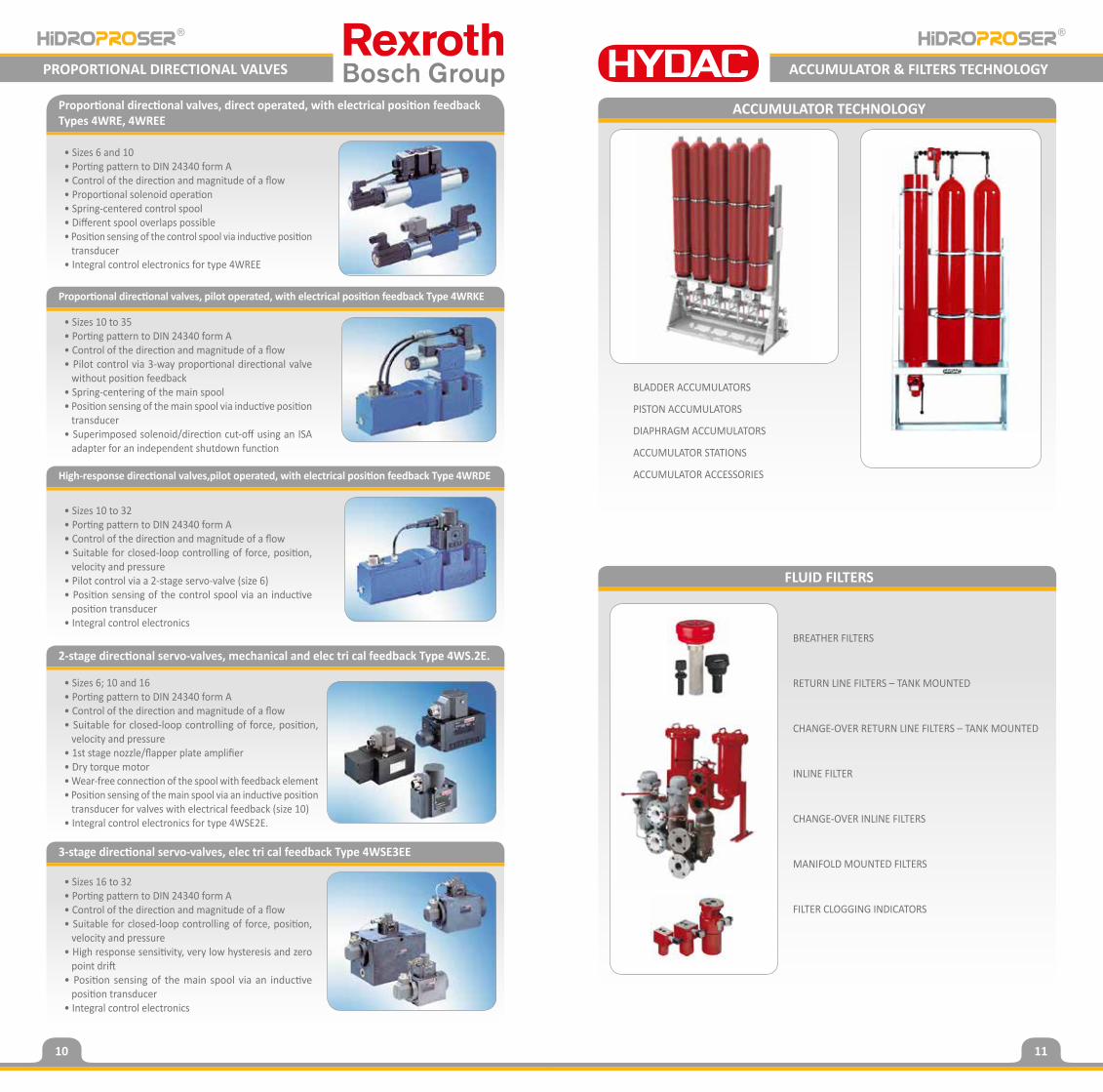
• Sizes 10 to 35• Porting pattern to DIN 24340 form A• Control of the direction and magnitude of a flow• Pilot control via 3-way proportional directional valve
without position feedback• Spring-centering of the main spool• Position sensing of the main spool via inductive position
transducer• Superimposed solenoid/direction cut-off using an ISA
adapter for an independent shutdown function
BLADDER ACCUMULATORS
PISTON ACCUMULATORS
DIAPHRAGM ACCUMULATORS
ACCUMULATOR STATIONS
ACCUMULATOR ACCESSORIES
BREATHER FILTERS
RETURN LINE FILTERS – TANK MOUNTED
CHANGE-OVER RETURN LINE FILTERS – TANK MOUNTED
INLINE FILTER
CHANGE-OVER INLINE FILTERS
MANIFOLD MOUNTED FILTERS
FILTER CLOGGING INDICATORS
Proportional directional valves, pilot operated, with electrical position feedback Type 4WRKE
ACCUMULATOR TECHNOLOGY
PROPORTIONAL DIRECTIONAL VALVES ACCUMULATOR & FILTERS TECHNOLOGY
FLUID FILTERS
• Sizes 6 and 10• Porting pattern to DIN 24340 form A• Control of the direction and magnitude of a flow• Proportional solenoid operation• Spring-centered control spool• Different spool overlaps possible• Position sensing of the control spool via inductive position
transducer• Integral control electronics for type 4WREE
Proportional directional valves, direct operated, with electrical position feedback Types 4WRE, 4WREE
• Sizes 10 to 32• Porting pattern to DIN 24340 form A• Control of the direction and magnitude of a flow• Suitable for closed-loop controlling of force, position,
velocity and pressure• Pilot control via a 2-stage servo-valve (size 6)• Position sensing of the control spool via an inductive
position transducer• Integral control electronics
• Sizes 6; 10 and 16• Porting pattern to DIN 24340 form A• Control of the direction and magnitude of a flow• Suitable for closed-loop controlling of force, position,
velocity and pressure• 1st stage nozzle/flapper plate amplifier• Dry torque motor• Wear-free connection of the spool with feedback element• Position sensing of the main spool via an inductive position
transducer for valves with electrical feedback (size 10)• Integral control electronics for type 4WSE2E.
High-response directional valves,pilot operated, with electrical position feedback Type 4WRDE
2-stage directional servo-valves, mechanical and elec tri cal feedback Type 4WS.2E.
• Sizes 16 to 32• Porting pattern to DIN 24340 form A• Control of the direction and magnitude of a flow• Suitable for closed-loop controlling of force, position,
velocity and pressure• High response sensitivity, very low hysteresis and zero
point drift• Position sensing of the main spool via an inductive
position transducer• Integral control electronics
3-stage directional servo-valves, elec tri cal feedback Type 4WSE3EE
10 11
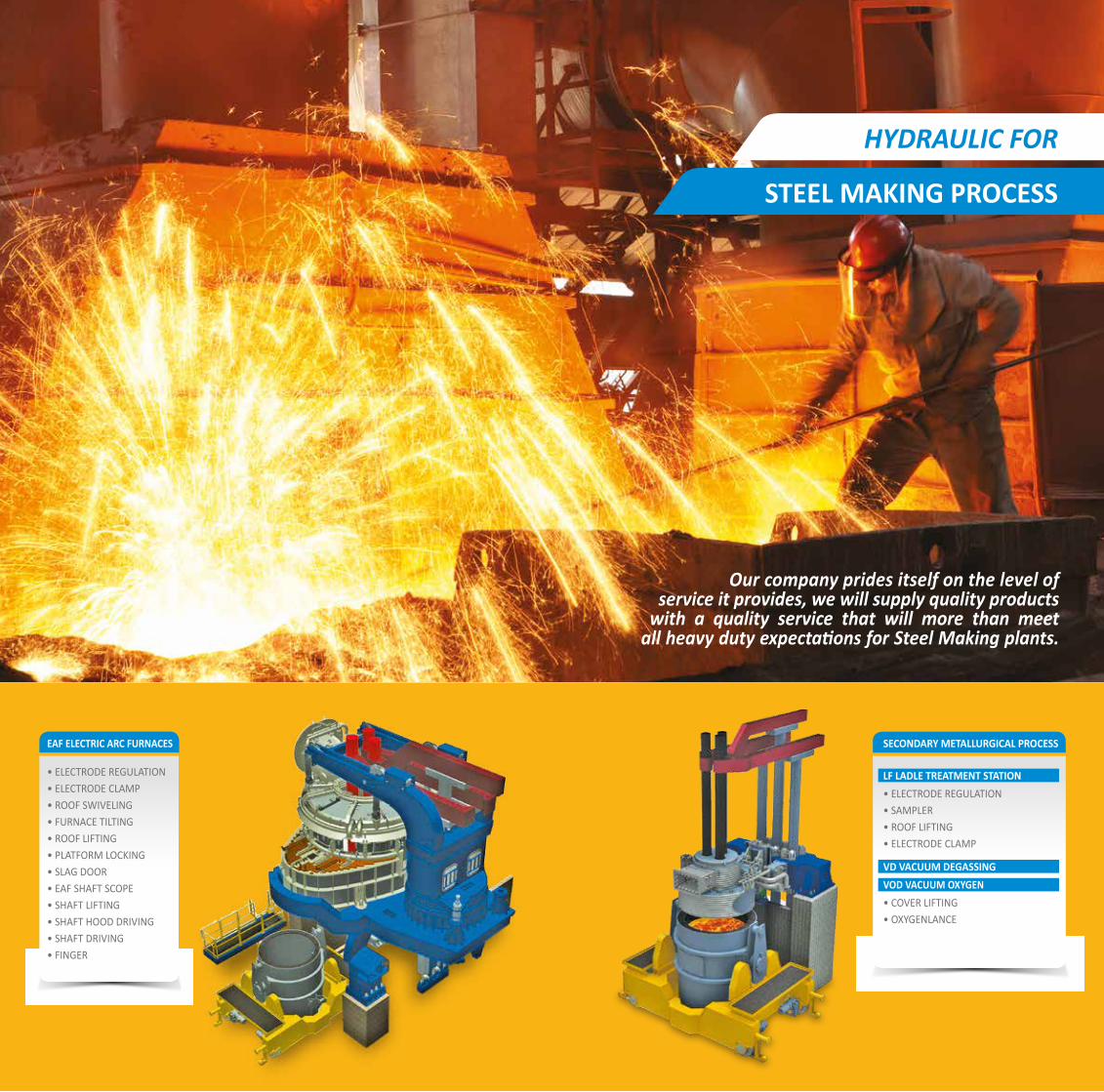
HYDRAULIC FOR
STEEL MAKING PROCESS
EAF ELECTRIC ARC FURNACES
• ELECTRODE REGULATION• ELECTRODE CLAMP• ROOF SWIVELING• FURNACE TILTING• ROOF LIFTING• PLATFORM LOCKING• SLAG DOOR• EAF SHAFT SCOPE• SHAFT LIFTING• SHAFT HOOD DRIVING• SHAFT DRIVING• FINGER
Our company prides itself on the level of service it provides, we will supply quality products with a quality service that will more than meetall heavy duty expectations for Steel Making plants.
SECONDARY METALLURGICAL PROCESS
LF LADLE TREATMENT STATION• ELECTRODE REGULATION• SAMPLER• ROOF LIFTING• ELECTRODE CLAMP
VD VACUUM DEGASSINGVOD VACUUM OXYGEN• COVER LIFTING• OXYGENLANCE
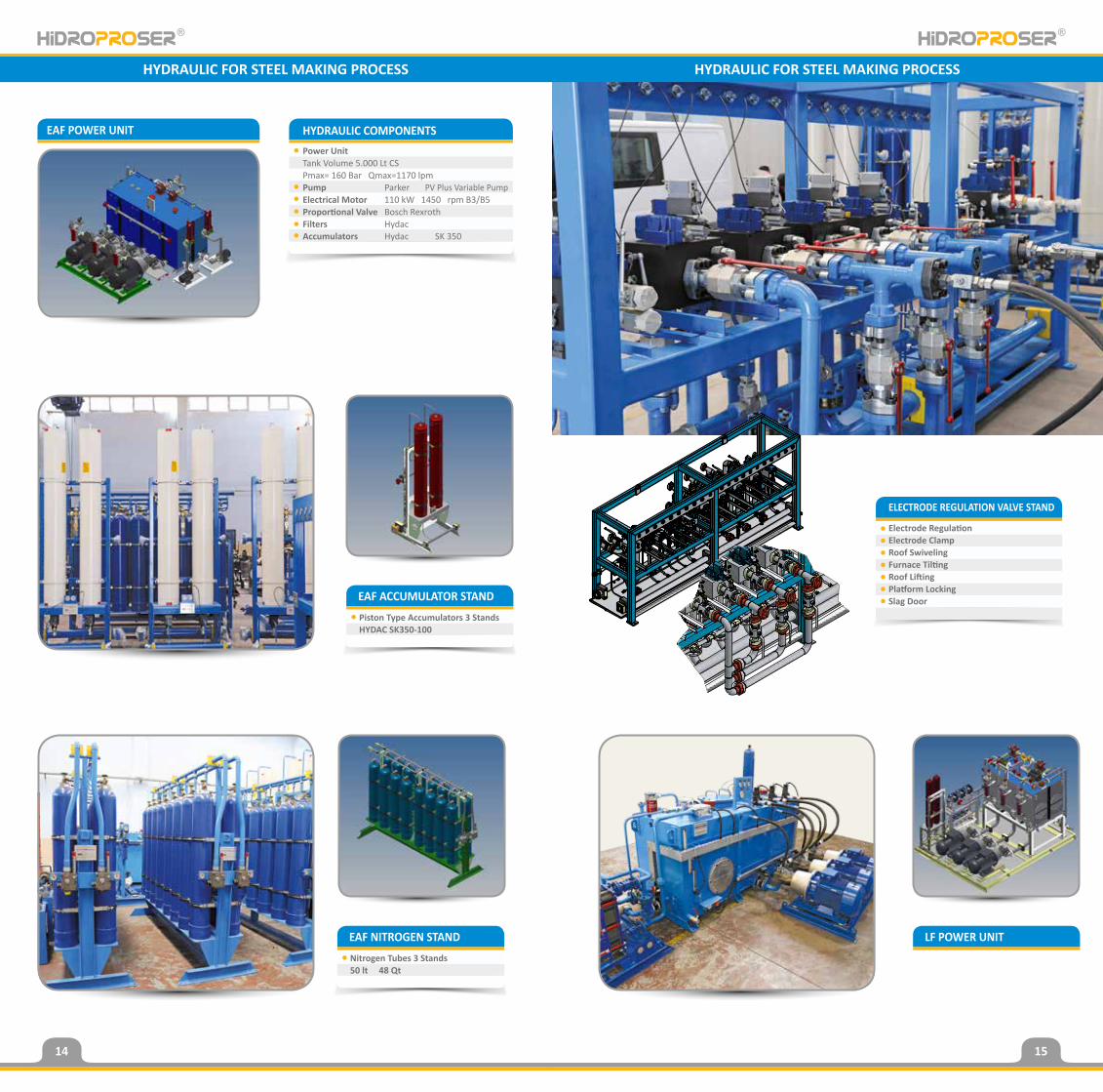
EAF POWER UNIT HYDRAULIC COMPONENTSPower UnitTank Volume 5.000 Lt CSPmax= 160 Bar Qmax=1170 lpm Pump Parker PV Plus Variable PumpElectrical Motor 110 kW 1450 rpm B3/B5Proportional Valve Bosch RexrothFilters HydacAccumulators Hydac SK 350
ELECTRODE REGULATION VALVE STAND
Electrode RegulationElectrode ClampRoof SwivelingFurnace TiltingRoof LiftingPlatform LockingSlag DoorEAF ACCUMULATOR STAND
Piston Type Accumulators 3 StandsHYDAC SK350-100
EAF NITROGEN STANDNitrogen Tubes 3 Stands50 lt 48 Qt
LF POWER UNIT
HYDRAULIC FOR STEEL MAKING PROCESS HYDRAULIC FOR STEEL MAKING PROCESS
14 15

LONG PRODUCT CASTING
• Tundish Car• Ladle Turret Arm• Ladle Turret Turning• Slide Gate• Quick Nozzle Change• Mould Ossilation• Withdrawal • Straightening• Rigid Dummy Bar• Torch Cutting• Cross Transfer• Cooling Bed - Lift Cooling Bed - Traveling Cooling Bed
BLOOM CASTING
• Tundish Car• Ladle Turret Arm• Ladle Turret Turning• Slide Gate• Quick Nozzle Change• Mould Oscillation• Withdrawal • Straightening• Rigid Dummy Bar• Torch Cutting• Cross Transfer• Cooling Bed - Lift Cooling Bed - Traveling Cooling Bed
SLAB - PLATE CASTING
• Tundish Car• Mould Oscillation• Segment• Segment Car• Torch Cutting
Hidroproser guarantees all work undertaken to comply with all relevant requirements of the customer’s specification; certification and documentation will be provided on completion or on request.
HYDRAULIC FOR
CASTING TECHNOLOGY PROCESS
1550
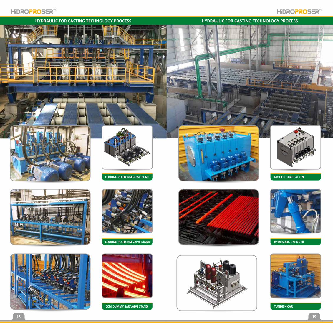
CCM-DUMMY BAR VALVE STAND TUNDISH CAR
COOLING PLATFORM VALVE STAND
COOLING PLATFORM POWER UNIT
HYDRAULIC CYLINDER
MOULD LUBRICATION
HYDRAULIC FOR CASTING TECHNOLOGY PROCESS HYDRAULIC FOR CASTING TECHNOLOGY PROCESS
18 19
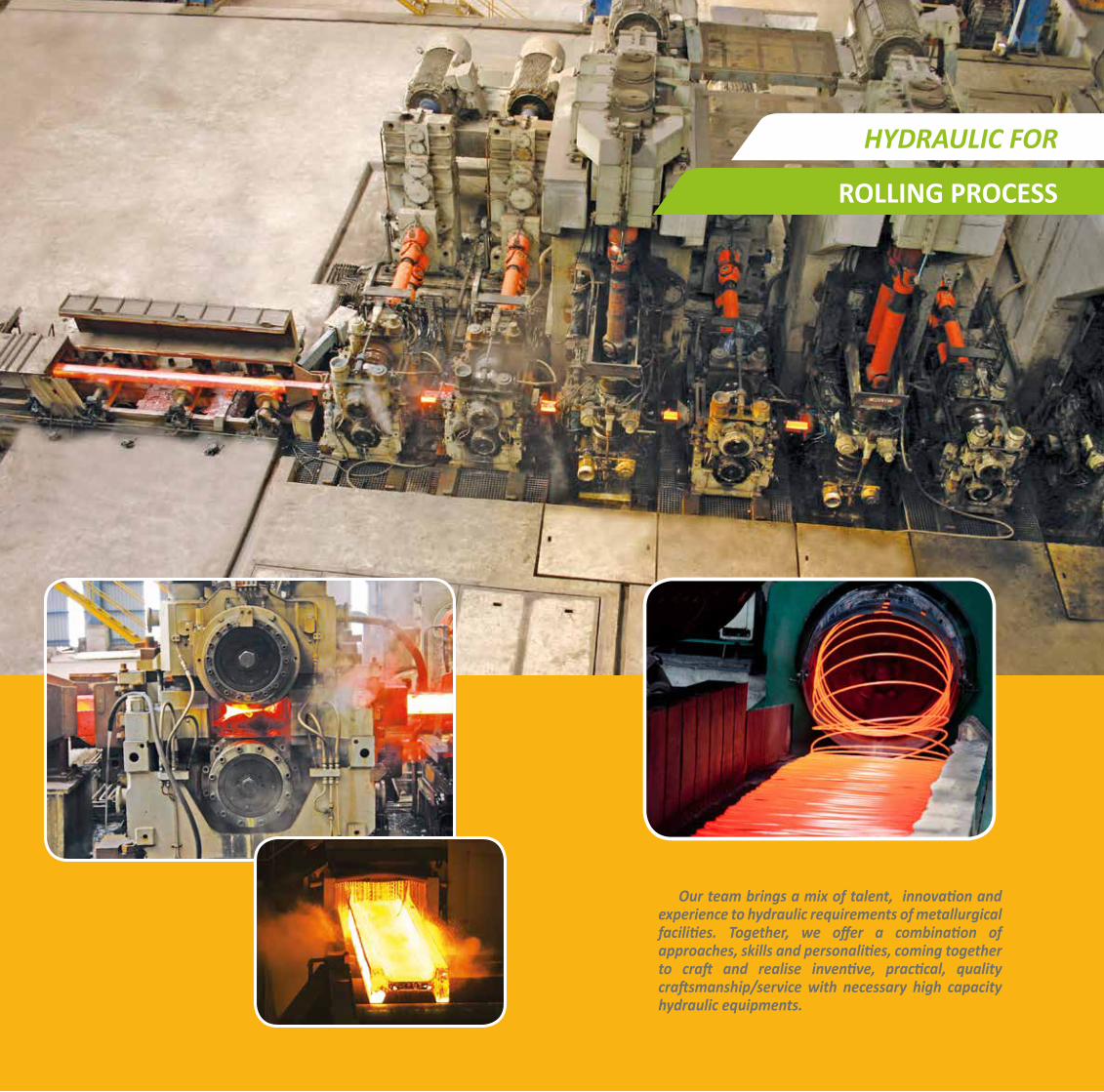
Our team brings a mix of talent, innovation and experience to hydraulic requirements of metallurgical facilities. Together, we offer a combination of approaches, skills and personalities, coming together to craft and realise inventive, practical, quality craftsmanship/service with necessary high capacity hydraulic equipments.
HYDRAULIC FOR
ROLLING PROCESS
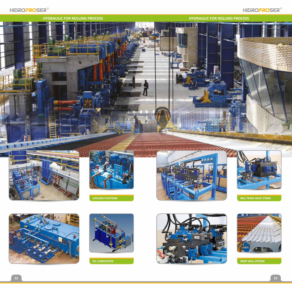
HYDRAULIC FOR ROLLING PROCESS HYDRAULIC FOR ROLLING PROCESS
OIL LUBRICATION DROP WALL SYSTEM
COOLING PLATFORM MILL TRAIN VALVE STAND
22 23
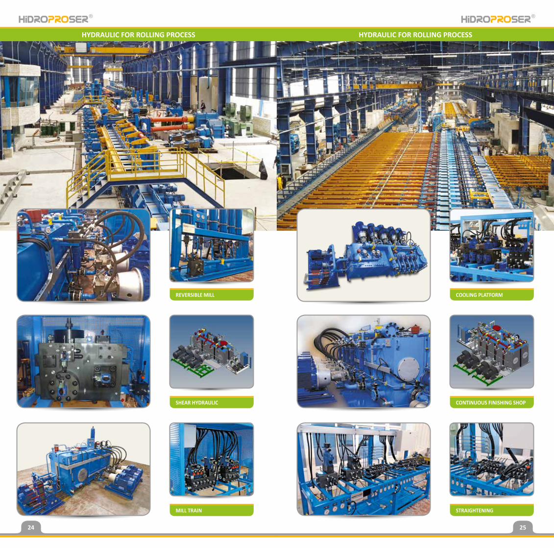
HYDRAULIC FOR ROLLING PROCESSHYDRAULIC FOR ROLLING PROCESS HYDRAULIC FOR ROLLING PROCESS
MILL TRAIN STRAIGHTENING
SHEAR HYDRAULIC
REVERSIBLE MILL
CONTINUOUS FINISHING SHOP
COOLING PLATFORM
24 25
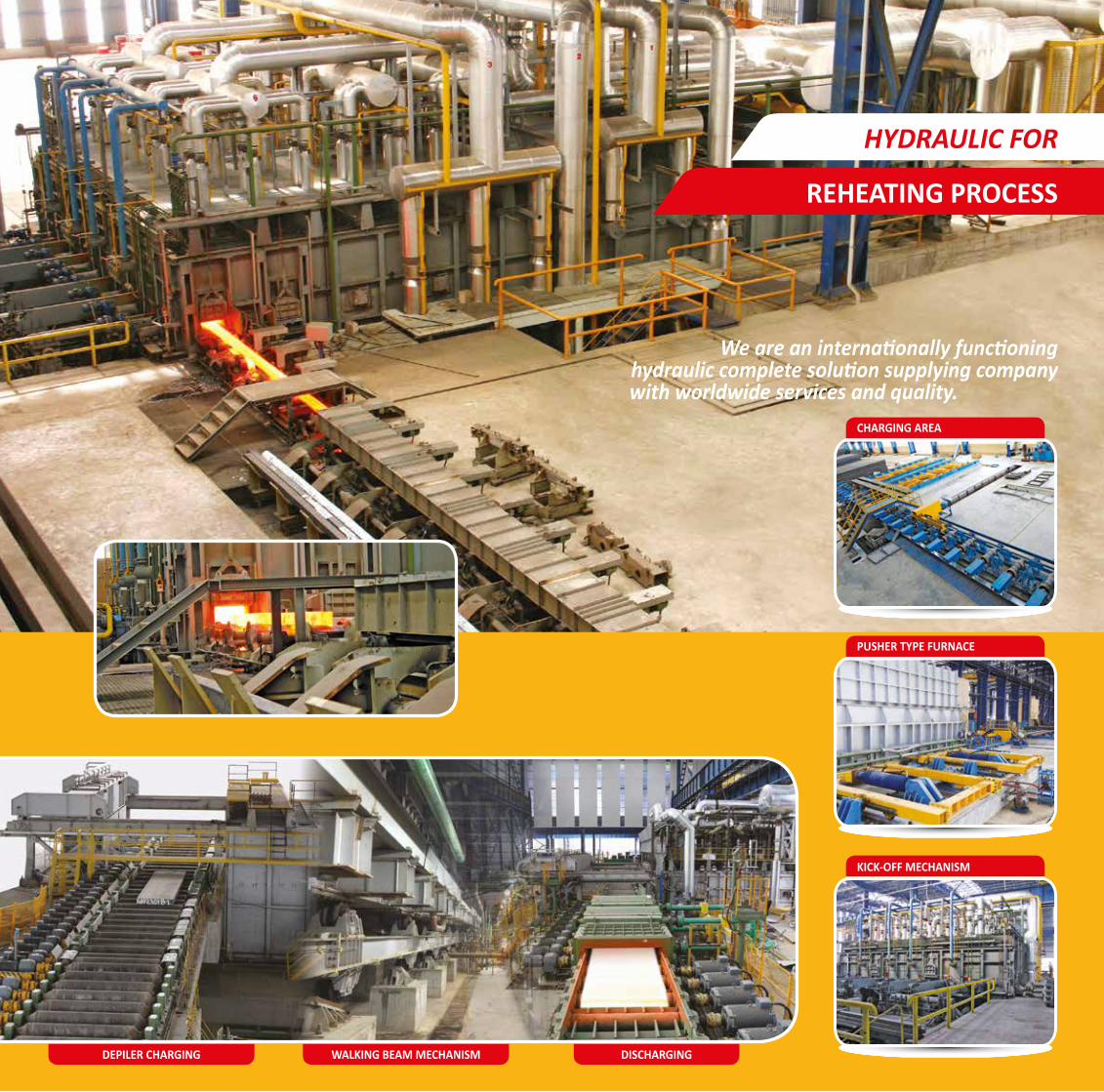
We are an internationally functioninghydraulic complete solution supplying company
with worldwide services and quality.CHARGING AREA
KICK-OFF MECHANISM
WALKING BEAM MECHANISM DISCHARGING
PUSHER TYPE FURNACE
HYDRAULIC FOR
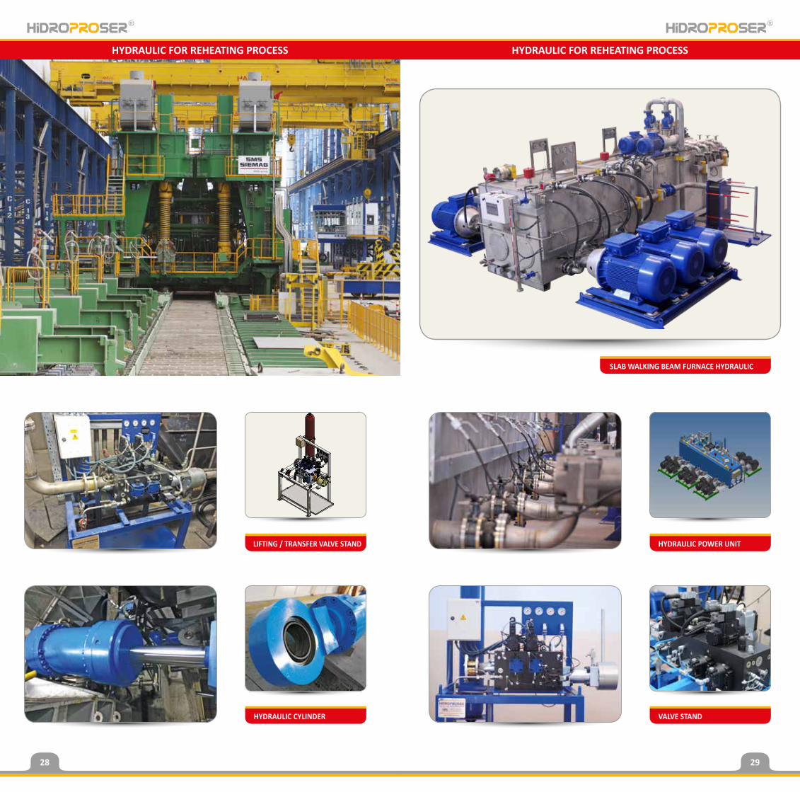
REHEATING PROCESS
DEPILER CHARGING
HYDRAULIC FOR REHEATING PROCESS HYDRAULIC FOR REHEATING PROCESS
HYDRAULIC CYLINDER VALVE STAND
LIFTING / TRANSFER VALVE STAND HYDRAULIC POWER UNIT
SLAB WALKING BEAM FURNACE HYDRAULIC
28 29
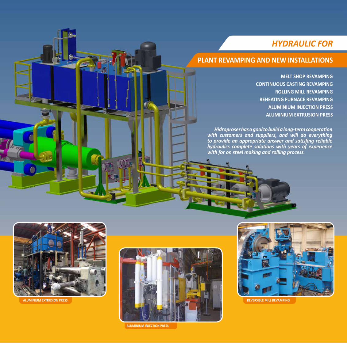
Hidroproser has a goal to build a long-term cooperation with customers and suppliers, and will do everything to provide an appropriate answer and satisfing reliable hydraulics complete solutions with years of experience with for on steel making and rolling process.
MELT SHOP REVAMPINGCONTINUOUS CASTING REVAMPING
ROLLING MILL REVAMPINGREHEATING FURNACE REVAMPING
ALUMINIUM INJECTION PRESSALUMINIUM EXTRUSION PRESS
HYDRAULIC FOR
PLANT REVAMPING AND NEW INSTALLATIONS
ALUMINIUM EXTRUSION PRESS
ALUMINIUM INJECTION PRESS
REVERSIBLE MILL REVAMPING

PRESS HYDRAULIC SYSTEMS PRESS HYDRAULIC SYSTEMS
ALUMINUM EXTRUSION PRESS
HYDRAULIC BILLET SHEAR
SCRAP PRESS
FORGING PRESS
32 33
35
www.completehydraulicsolutions.com www.completehydraulicsolutions.com
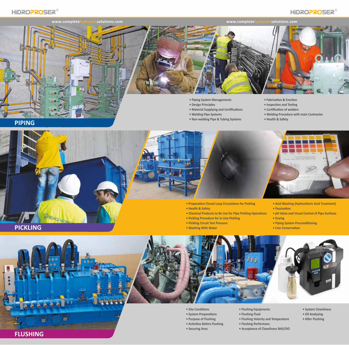
PIPING
FLUSHING
PICKLING
• Piping System Managements• Design Principles• Material Supplying and Certifications• Welding Pipe Systems• Non-welding Pipe & Tubing Systems
• Fabrication & Erection• Inspection and Testing• Certification of welders• Welding Procedure with main Contractor• Health & Safety
• Preparation Closed Loop Circulations for Pickling• Health & Safety• Chemical Products to Be Use for Pipe Pickling Operations• Pickling Procedure for in Line Pickling• Pickling Circuit Test Pressure• Washing With Water
• Acid Washing (Hydrochloric Acid Treatment)• Passivation• pH Value and Visual Control of Pipe Surfaces• Drying• Piping System Preconditioning• Line Conservation
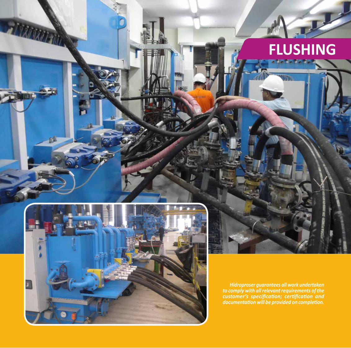
• Site Conditions• System Preparations• Purpose of Flushing• Activities Before Flushing• Securing Area
• Flushing Equipments• Flushing Fluid• Flushing Velocity and Temperature• Flushing Performans• Acceptance of Cleanliness NAS/ISO
• System Cleanliness• Oil Analyzing• After Flushing
36 37
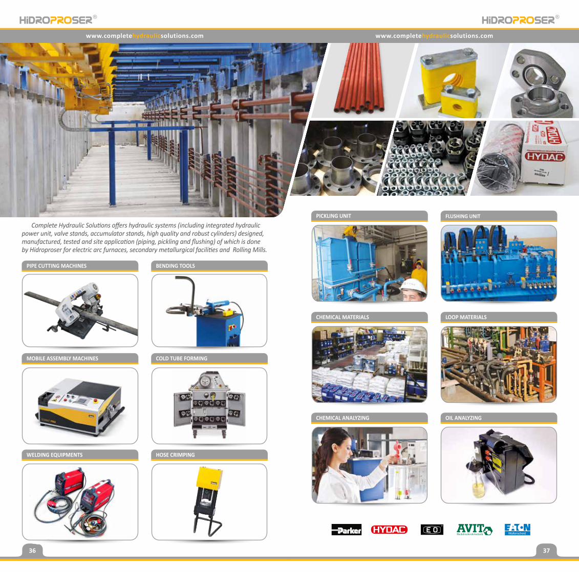
BENDING TOOLS
PICKLING UNIT FLUSHING UNIT
MOBILE ASSEMBLY MACHINES COLD TUBE FORMING
CHEMICAL MATERIALS LOOP MATERIALS
WELDING EQUIPMENTS HOSE CRIMPING
CHEMICAL ANALYZING OIL ANALYZING
www.completehydraulicsolutions.com www.completehydraulicsolutions.com
PIPE CUTTING MACHINES
Complete Hydraulic Solutions offers hydraulic systems (including integrated hydraulic power unit, valve stands, accumulator stands, high quality and robust cylinders) designed, manufactured, tested and site application (piping, pickling and flushing) of which is done by Hidroproser for electric arc furnaces, secondary metallurgical facilities and Rolling Mills.
38
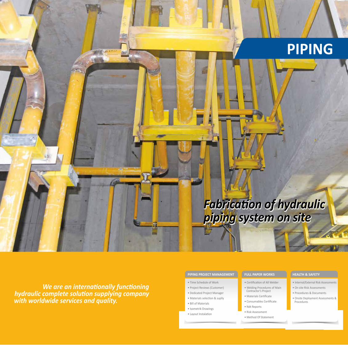
PIPING PROJECT MANAGEMENT
• Time Schedule of Work
• Project Reviews (Customer)
• Dedicated Project Manager
• Materials selection & suplly
• Bill of Materials
• Isometrik Drawings
• Layout Instalation
FULL PAPER WORKS
• Certification of All Welder
• Welding Procedures of Main Contractor’s Project
• Materials Certificate
• Consumables Certificate
• Ndt Reports
• Risk Assessment
• Method Of Statement
HEALTH & SAFETY
• Internal/External Risk Assessments
• On site Risk Assessments
• Procedures & Documents
• Onsite Deployment Assessments & Procedures
PIPING
We are an internationally functioninghydraulic complete solution supplying company
with worldwide services and quality.
Fabrication of hydraulic piping system on siteFabrication of hydraulic piping system on site

40 41
PIPING
PIPING
PIPING
PIPING PIPING
FITTINGS AND FLANGESPIPING SYSTEM DESIGN
Hydraulic systems are designed according to a working pressure that the required forces and torq are achieved. Hydraulic system are generaly designed much more approxiamately than 15-20 % the working pressure. All components should be selected to meet the maxiumum system pressure.
At the same time all design parameters have to be selected specifically for each the system and the customers’ requirements, rules, regulations and certifications.
SELECTION OF PIPE SIZEThe inner diameter and wall thickness of the pipes are determination of correct pipe size. The inner diameter selected according to on allowed pressure losses or on flow velocity. The wall thickness is selected according to on the required pressure rating.
PIPE AND TUBE MATERIALS
The recommended pipe and tube materials to be used in hydraulic applications are as follows:
FLOW VELOCITY
d = inner diameter of the pipe [mm]Qmax = maximum flow rate [Lpm]v = flow velocity [m/s]The Reynolds number can be determination of flow type inside of pipe.
• Laminar flow Re < 2300• Turbulent flow Re > 4000The critical Reynolds number should be Rekr for typical hydraulic pipe flow is 2500.
MECHANICAL DESIGN• Pipe & Tube Material• Connection System: Welding, Fittings, Flanges• Pipe Supports
PIPING
Steel Type Tensile Strength Yield Point Ductile Yield Condition
EN10220(st52-3 acc.to DIN2448) 490 N/mm² (St52.3) 345 N/mm² (St52.3) 20% min. (St52.3) Seamless non-alloy steel
tubes for pressure purposes
TUBINGSteel Type Tensile Strength Yield Point Ductile yield Condition
Fine grain E235N acc.to EN10305-4 (St.37.4 acc.to
DIN 1630/DIN2391)340 N/mm² 235 N/mm² 25 % min
Seamless, cold drawn, normal annealed, DIN EN 10305-1 and 4 Phosphated and
oiled
BUTT WELDING METHOD250 Bar 315 Bar 400 Bar
NominalSize
OutsideDiameter
(mm)
WallThickness
(mm)
OutsideDiameter
(mm)
WallThickness
(mm)
OutsideDiameter
(mm)
WallThickness
(mm)
DN 25 33,7 4,5 - - 42,4 8,8
DN 32 42,4 5,6 48,3 8 48,3 8,8
DN 40 60,3 8 60 10 60,3 11
DN 50 76,1 10 76,1 12,5 76,1 14,2
DN 65 88,9 12,5 88,9 14,2 101,6 20
DN 80 101,6 14,2 114,3 20 133 25
DN 100 139,7 20 152,5 28 152,4 30
DN 125 168,3 22 177,8 30 219,1 45
DN 150 193,7 25 219,1 38 - -
Q = V * Ad = 4 . Qmax
∏ . v
FLUID (OIL) VELOCITIESRecommended oil velocities to be utilized for initial pipe sizing in suction and pressure lines can be
250 Bar 315 Bar 400 BarOutside
Diameter(mm)
WallThickness
(mm)
OutsideDiameter
(mm)
WallThickness
(mm)
OutsideDiameter
(mm)
WallThickness
(mm)8 1 8 1,5 8 1,5
10 1 10 1,5 10 212 1,5 12 1,5 - -16 2 16 2 16 318 2 18 2,5 - -20 2 20 2,5 20 422 2,5 - - - -25 2,5 25 4 25 4,528 3 - - - -30 3 30 4 30 535 3 - - - -38 4 38 5 - -42 4 - - - -
PIPING Standard CarbonStainless
Austenitic Acid-proof
EN 10 027 E235 E355 - - -
DIN 1630 St 37.4 St 52.4 - - -
DIN 1629 St 35 St 52 - - -Material N. (EN) 1.0380 1.0580 1.4307 1.4571 1.4404ASTM/SAE A53Gr. A A252Gr. 3
Alloy Steel (EN) - - X2 CrNi 1811
X6 CrNiMoTi17 12 2
X2 CrNiMo17 13 2
AISI - - 304L 316Ti 316L
BUTT WELDING METHOD
SERIE 3000 PSI SERIE 6000 PSI
NominalSize
OutsideDiameter
(mm)
WallThickness
(mm)
OutsideDiameter
(mm)
WallThickness
(mm)
DN 25 33,7 4 33,7 5
DN 32 42,4 4 42,4 6,3
DN 40 48,3 4 48,3 7,1
DN 50 60,3 4,5 60,3 8
DN 65 76,1 4,5 76,1 10
DN 80 88,9 5 88,9 12,5
DN 100 114,3 3,6 - -
DN 125 139,7 4,5 - -
SOCKET WELDING METHOD
SERIE 3000 PSI SERIE 6000 PSI
NominalSize
OutsideDiameter
(mm)
WallThickness
(mm)
OutsideDiameter
(mm)
WallThickness
(mm)
DN 25 33,7 4 33,7 5
DN 32 42,4 4 42,4 6,3
DN 40 48,3 4 48,3 7,1
DN 50 60,3 4,5 60,3 8
Suction lines ≤ 1 m/snPressure lines ≤ 5 m/s.Return lines ≤ 3 m/s.
42 43
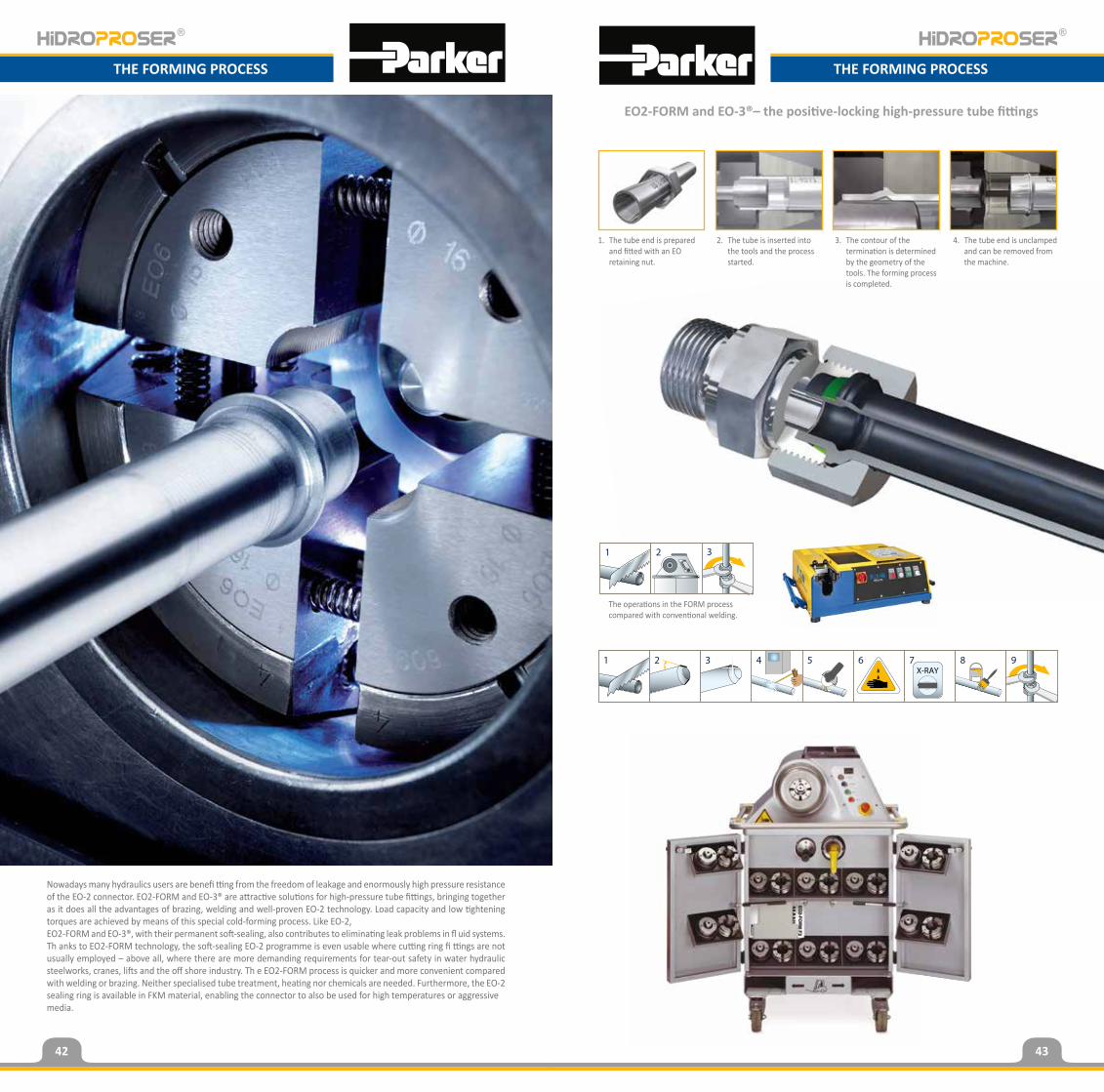
EO2-FORM and EO-3®– the positive-locking high-pressure tube fittings
Nowadays many hydraulics users are benefi tting from the freedom of leakage and enormously high pressure resistance of the EO-2 connector. EO2-FORM and EO-3® are attractive solutions for high-pressure tube fittings, bringing together as it does all the advantages of brazing, welding and well-proven EO-2 technology. Load capacity and low tightening torques are achieved by means of this special cold-forming process. Like EO-2,EO2-FORM and EO-3®, with their permanent soft-sealing, also contributes to eliminating leak problems in fl uid systems. Th anks to EO2-FORM technology, the soft-sealing EO-2 programme is even usable where cutting ring fi ttings are not usually employed – above all, where there are more demanding requirements for tear-out safety in water hydraulic steelworks, cranes, lifts and the off shore industry. Th e EO2-FORM process is quicker and more convenient compared with welding or brazing. Neither specialised tube treatment, heating nor chemicals are needed. Furthermore, the EO-2 sealing ring is available in FKM material, enabling the connector to also be used for high temperatures or aggressivemedia.
1. The tube end is prepared and fitted with an EO retaining nut.
The operations in the FORM processcompared with conventional welding.
2. The tube is inserted into the tools and the process started.
3. The contour of the termination is determined by the geometry of the tools. The forming process is completed.
4. The tube end is unclamped and can be removed from the machine.
THE FORMING PROCESSTHE FORMING PROCESS
44 45
PIPING PIPING
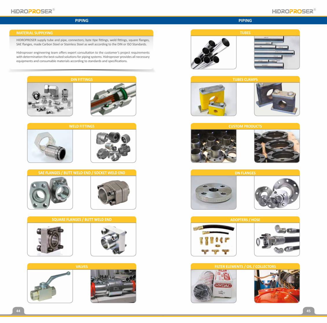
MATERIAL SUPPLYING
HIDROPROSER supply tube and pipe, connectors; byte tipe fittings, weld fittings, square flanges, SAE flanges, made Carbon Steel or Stainless Steel as well according to the DIN or ISO Standards.
Hidroproser engineering team offers expert consultation to the customer’s project requirements with determination the best-suited solutions for piping systems. Hidroproser provides all necessary equipments and consumable materials according to standards and specifications.
WELD FITTINGS
DIN FITTINGS
SAE FLANGES / BUTT WELD END / SOCKET WELD END
SQUARE FLANGES / BUTT WELD END
VALVES
TUBES
TUBES CLAMPS
CUSTOM PRODUCTS
DN FLANGES
ADOPTERS / HOSE
FILTER ELEMENTS / OIL / COLLECTORS
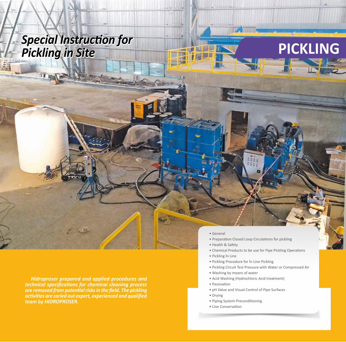
PICKLINGSpecial Instruction for Pickling in Site
• General• Preparation Closed Loop Circulations for pickling• Health & Safety• Chemical Products to be use for Pipe Pickling Operations• Pickling İn Line• Pickling Procedure for İn Line Pickling• Pickling Circuit Test Pressure with Water or Compressed Air• Washing by means of water• Acid Washing (Hydrochloric Acid treatment)• Passivation • pH Value and Visual Control of Pipe Surfaces • Drying• Piping System Preconditioning• Line Conservation
Hidroproser prepared and applied procedures and technical specifications for chemical cleaning process are removed from potential risks in the field. The pickling activities are caried out expert, experienced and qualified team by HIDROPROSER.
Special Instruction for Pickling in Site
FLUSHING
Hidroproser guarantees all work undertaken to comply with all relevant requirements of the customer’s specification; certification and documentation will be provided on completion.
50 51
FLUSHING
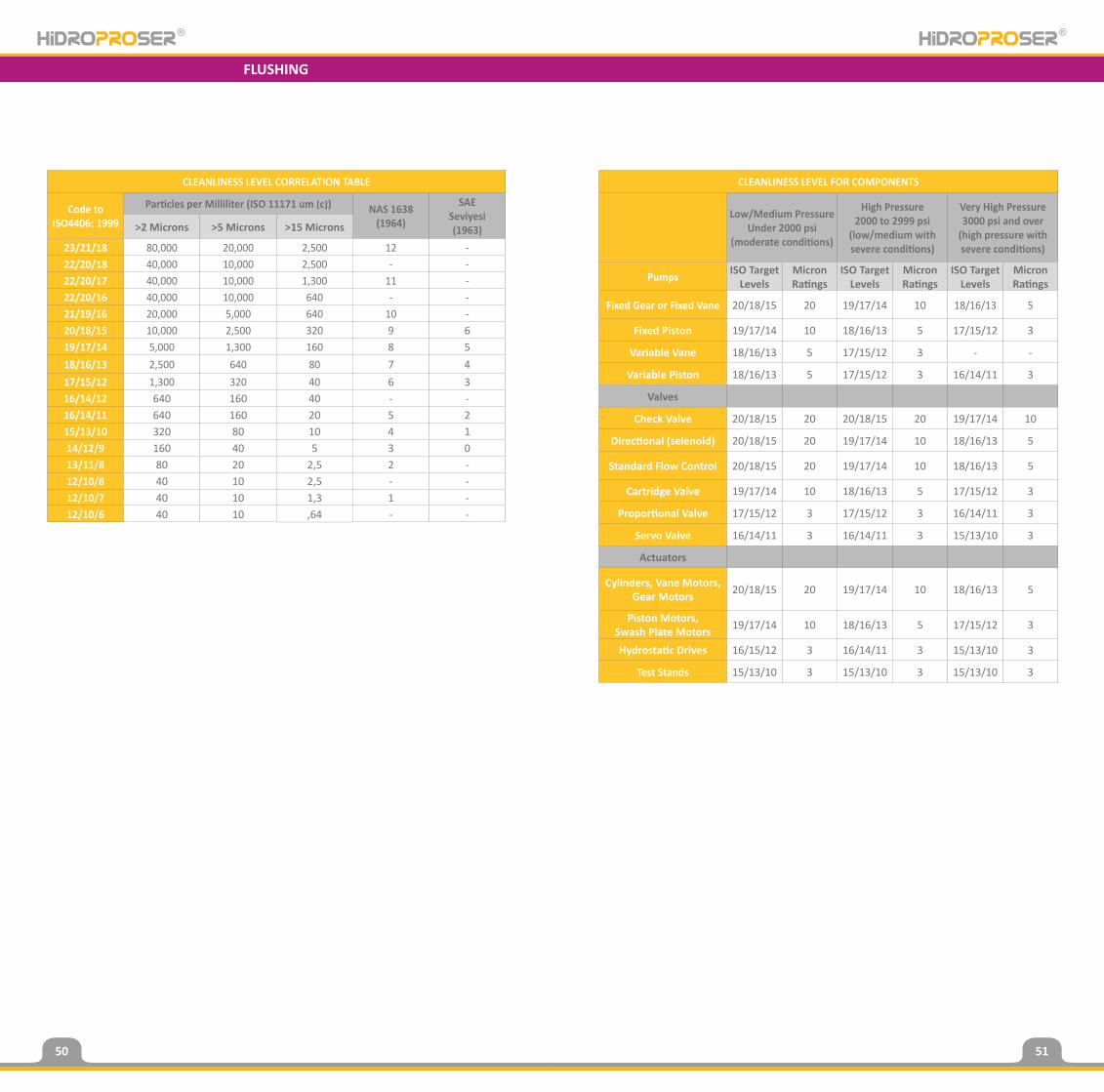
CLEANLINESS LEVEL CORRELATION TABLE
Code toISO4406: 1999
Particles per Milliliter (ISO 11171 um �c�) NAS 1638(1964)
SAESeviyesi(1963)>2 Microns >5 Microns >15 Microns
23/21/18 80,000 20,000 2,500 12 -22/20/18 40,000 10,000 2,500 - -22/20/17 40,000 10,000 1,300 11 -22/20/16 40,000 10,000 640 - -21/19/16 20,000 5,000 640 10 -20/18/15 10,000 2,500 320 9 619/17/14 5,000 1,300 160 8 518/16/13 2,500 640 80 7 417/15/12 1,300 320 40 6 316/14/12 640 160 40 - -16/14/11 640 160 20 5 215/13/10 320 80 10 4 114/12/9 160 40 5 3 013/11/8 80 20 2,5 2 -12/10/8 40 10 2,5 - -12/10/7 40 10 1,3 1 -12/10/6 40 10 ,64 - -
CLEANLINESS LEVEL FOR COMPONENTS
Low/Medium PressureUnder 2000 psi
(moderate conditions)
High Pressure2000 to 2999 psi
(low/medium with severe conditions)
Very High Pressure3000 psi and over
(high pressure with severe conditions)
Pumps ISO TargetLevels
Micron Ratings
ISO TargetLevels
Micron Ratings
ISO TargetLevels
Micron Ratings
Fixed Gear or Fixed Vane 20/18/15 20 19/17/14 10 18/16/13 5
Fixed Piston 19/17/14 10 18/16/13 5 17/15/12 3
Variable Vane 18/16/13 5 17/15/12 3 - -
Variable Piston 18/16/13 5 17/15/12 3 16/14/11 3
Valves
Check Valve 20/18/15 20 20/18/15 20 19/17/14 10
Directional (selenoid) 20/18/15 20 19/17/14 10 18/16/13 5
Standard Flow Control 20/18/15 20 19/17/14 10 18/16/13 5
Cartridge Valve 19/17/14 10 18/16/13 5 17/15/12 3
Proportional Valve 17/15/12 3 17/15/12 3 16/14/11 3
Servo Valve 16/14/11 3 16/14/11 3 15/13/10 3
Actuators
Cylinders, Vane Motors,Gear Motors 20/18/15 20 19/17/14 10 18/16/13 5
Piston Motors,Swash Plate Motors 19/17/14 10 18/16/13 5 17/15/12 3
Hydrostatic Drives 16/15/12 3 16/14/11 3 15/13/10 3
Test Stands 15/13/10 3 15/13/10 3 15/13/10 3
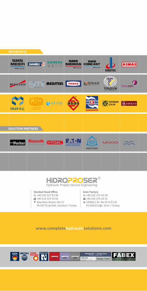
REFERENCES
SOLUTION PARTNERS
İstanbul Head Office+90 216 527 92 00+90 216 527 92 02Bayraktar Bulvarı No:57Pk:34775 Şerifali, İstanbul / Turkey
İzmir Factory+90 232 375 43 30+90 232 375 43 3110006/1 Sk. No:35 A.O.S.BPk:35620 Çiğli, İzmir / Turkey
www.completehydraulicsolutions.com