CHEETAH C4080 and C2880 Hardware User’s Manual · 2019-06-01 · CHEETAH Hardware User’s Manual...
154
CHEETAH Hardware User’s Manual IMPERX, Inc. Rev. 7.0 6421 Congress Ave. 6/13/2017 Boca Raton, FL 33487 +1 (561) 989-0006 1 of 154 CHEETAH C4080 and C2880 Hardware User’s Manual HIGH-SPEED, HIGH-RESOLUTION, AND VERSATILE CMOS DIGITAL CAMERAS CONFIDENTIAL NOTICE: These products are not intended for use in life support appliances, devices, or systems where malfunction of these products can reasonably be expected to result in personal injury. Imperx customers using or selling these products for use in such applications do so at their own risk and agree to fully indemnify Imperx for any damages resulting from such improper use or sale. Copyright © 2011, Imperx Inc. All rights reserved. All information provided in this manual is believed to be accurate and reliable. Imperx assumes no responsibility for its use. Imperx reserves the right to make changes to this information without notice. Redistribution of this manual in whole or in part, by any means, is prohibited without obtaining prior permission from Imperx.
Transcript of CHEETAH C4080 and C2880 Hardware User’s Manual · 2019-06-01 · CHEETAH Hardware User’s Manual...

CHEETAH Hardware User’s Manual
IMPERX, Inc. Rev. 7.0 6421 Congress Ave. 6/13/2017 Boca Raton, FL 33487 +1 (561) 989-0006 1 of 154
CHEETAH C4080 and C2880 Hardware User’s Manual
HIGH-SPEED, HIGH-RESOLUTION, AND VERSATILE CMOS DIGITAL
CAMERAS
CONFIDENTIAL NOTICE:
These products are not intended for use in life support appliances, devices, or systems where malfunction of these
products can reasonably be expected to result in personal injury. Imperx customers using or selling these products for
use in such applications do so at their own risk and agree to fully indemnify Imperx for any damages resulting from
such improper use or sale.
Copyright © 2011, Imperx Inc. All rights reserved. All information provided in this manual is believed to be accurate
and reliable. Imperx assumes no responsibility for its use. Imperx reserves the right to make changes to this information
without notice. Redistribution of this manual in whole or in part, by any means, is prohibited without obtaining prior
permission from Imperx.
CHEETAH Hardware User’s Manual
IMPERX, Inc. Rev. 7.0 6421 Congress Ave. 6/13/2017 Boca Raton, FL 33487 +1 (561) 989-0006 2 of 154
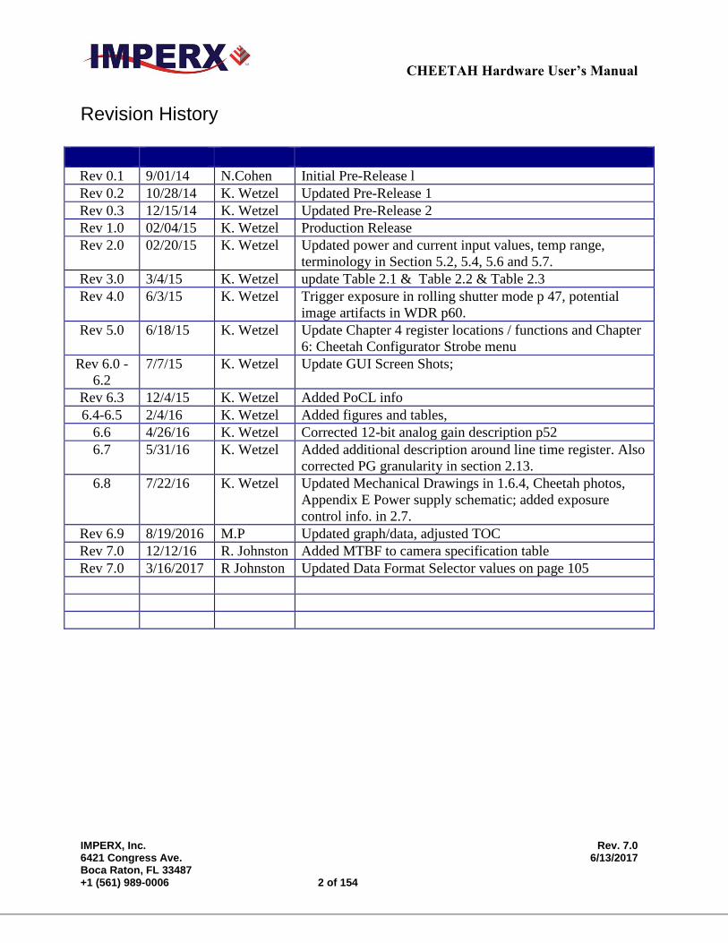
Revision History
Rev 0.1 9/01/14 N.Cohen Initial Pre-Release l
Rev 0.2 10/28/14 K. Wetzel Updated Pre-Release 1
Rev 0.3 12/15/14 K. Wetzel Updated Pre-Release 2
Rev 1.0 02/04/15 K. Wetzel Production Release
Rev 2.0 02/20/15 K. Wetzel Updated power and current input values, temp range,
terminology in Section 5.2, 5.4, 5.6 and 5.7.
Rev 3.0 3/4/15 K. Wetzel update Table 2.1 & Table 2.2 & Table 2.3
Rev 4.0 6/3/15 K. Wetzel Trigger exposure in rolling shutter mode p 47, potential
image artifacts in WDR p60.
Rev 5.0 6/18/15 K. Wetzel Update Chapter 4 register locations / functions and Chapter
6: Cheetah Configurator Strobe menu
Rev 6.0 -
6.2
7/7/15 K. Wetzel Update GUI Screen Shots;
Rev 6.3 12/4/15 K. Wetzel Added PoCL info
6.4-6.5 2/4/16 K. Wetzel Added figures and tables,
6.6 4/26/16 K. Wetzel Corrected 12-bit analog gain description p52
6.7 5/31/16 K. Wetzel Added additional description around line time register. Also
corrected PG granularity in section 2.13.
6.8 7/22/16 K. Wetzel Updated Mechanical Drawings in 1.6.4, Cheetah photos,
Appendix E Power supply schematic; added exposure
control info. in 2.7.
Rev 6.9 8/19/2016 M.P Updated graph/data, adjusted TOC
Rev 7.0 12/12/16 R. Johnston Added MTBF to camera specification table
Rev 7.0 3/16/2017 R Johnston Updated Data Format Selector values on page 105
CHEETAH Hardware User’s Manual
IMPERX, Inc. Rev. 7.0 6421 Congress Ave. 6/13/2017 Boca Raton, FL 33487 +1 (561) 989-0006 3 of 154
TABLE OF CONTENTS
Contents
CHAPTER 1 – INTRODUCTION 10
1.0 CHEETAH FAMILY 11
1.1 GENERAL DESCRIPTION 11
1.2 MAIN CHEETAH FEATURES 13
1.3 CHEETAH SPECIFICATIONS 14 1.3.1 General Information 14
1.3.2 Spectral Sensitivity Curves 17 1.3.3 Bayer Pattern Information 18
1.4 TECHNICAL SPECIFICATIONS 19
1.5 CAMERA CONNECTIVITY 21 1.5.1 CLF (Full) - Camera Link (CL) Output 21
1.5.2 Camera Link Full Signal Mapping 21 1.5.3 Camera Link Physical Layer to Camera Link Receiver Bits 24
1.5.4 Camera Link Bit to Port Bit assignments 24 1.5.4 Camera Link Port assignments based on selected output configuration 28
1.5.4 Camera Power Connector 29
1.6 MECHANICAL, OPTICAL, and ENVIRONMENTAL 30 1.6.1 Mechanical 30
1.6.2 Optical 30 1.6.3 Environmental 31 1.6.4 Mechanical Drawings 32
CHAPTER 2 – CAMERA FEATURES 34
2.1 DUAL VIDEO (FRAME A / FRAME B) 35 2.1.1 Frame A / Frame B Description 35
2.1.2 Dual Video: Frame A / Frame B Switching Options 36
2.2 GLOBAL/ ROLLING SHUTTER 37
2.3 A/D DIGITIZATION 37
CHEETAH Hardware User’s Manual
IMPERX, Inc. Rev. 7.0 6421 Congress Ave. 6/13/2017 Boca Raton, FL 33487 +1 (561) 989-0006 4 of 154
2.4 FRAME TIME CONTROL 37 2.4.1 Internal Line and Frame Time Control 37 2.4.2 Camera Output Control 38
2.5 AREA OF INTEREST 39 2.5.1 Overview 39
2.5.2 Horizontal and Vertical Window 39 2.5.3 Factors Impacting Frame Rate 40
2.6 SUBSAMPLING 42 2.6.1 Pixel Averaging 42 2.6.2 Sub-sampling Decimation 43
2.7 EXPOSURE CONTROL 44 2.7.1 Internal Exposure Control - Electronic Shutter 44 2.7.3 External exposure control 47 2.7.4 Variable Frame Time – Programmable Line and Frame Time 47
2.8 CAMERA TRIGGERING 48 2.8.1 Triggering Inputs 48
2.8.2 Acquisition and Exposure Control 48 2.8.3 Triggering modes 49
2.9 STROBES 51
2.10 VIDEO AMPLIFIER GAIN AND OFFSET 52 2.10.1 Analog Domain – manual control 52 2.10.2 Digital Domain – manual control 53
2.11 WIDE DYNAMIC RANGE (WDR) 53 2.11.1 Overview 53 2.11.2 Wide Dynamic Range Controls 59
2.11.3 Initial WDR Setup Recommendations 62 2.11.4 WDR at maximum frame rates (image artifact prevention) 63
2.12 DATA OUTPUT FORMAT 64 2.12.1 Bit Depth 64 2.12.2 Output Taps 66
2.13 PULSE GENERATOR 66
2.14 I/O CONTROL 67 2.14.1 Input / Output Mapping 67 2.14.2 Electrical Connectivity 67
2.15 TEST IMAGE PATTERNS 69
CHEETAH Hardware User’s Manual
IMPERX, Inc. Rev. 7.0 6421 Congress Ave. 6/13/2017 Boca Raton, FL 33487 +1 (561) 989-0006 5 of 154
2.15.1Test Image patterns 69
2.16 WHITE BALANCE AND COLOR CONVERSION 70 2.16.1 White Balance Correction 70
2.17 TRANSFER FUNCTION CORRECTION – USER LUT 70 2.17.1 Standard Gamma Correction 71
2.17.2 User Defined LUT 72
2.18 DEFECTIVE PIXEL CORRECTION 73 2.18.1 Static Pixel Correction 73 2.18.2 Dynamic Pixel Correction 74
2.19 CAMERA INTERFACE 74 2.19.1 Status LED 74
2.19.2 Temperature Monitor 74 2.19.3 Exposure Time Monitor 74 2.19.4 Frame Time Monitor 75
2.19.5 Current image size 75
CHAPTER 3 CAMERA CONFIGURATION 76
3.1 OVERVIEW 77
3.2 CAMERA CONFIGURATION 77 3.2.1 Configuration Memory – parameter FLASH 77 3.2.2 Camera Serial Protocol 78
3.3 CAMERA CONFIGURATION REGISTER DESCRIPTION 81 3.3.1 Startup Procedure 81 3.3.2 Saving and Restoring Settings 81
3.3.3 Retrieving Manufacturing Data 83 3.3.4 Camera Information Registers 85
3.3.5 Frame “A” Workspace Registers 87 3.3.6 Frame “B” Workspace Registers 93 3.3.7 Acquisition Control Registers 98 3.3.8 Triggering Workspace Registers 99 3.3.9 Strobe Control Registers 100
3.3.10 Pulse Generator Workspace Registers 102 3.3.11 Test Pattern Workspace Registers 103
3.3.12 Input/output Workspace Registers 103 3.3.13 Data Output Bit Depth/Format Selector 104 3.3.14 White Balance (WB) Workspace Registers 105 3.3.15 Data Correction Workspace Registers 106
CHEETAH Hardware User’s Manual
IMPERX, Inc. Rev. 7.0 6421 Congress Ave. 6/13/2017 Boca Raton, FL 33487 +1 (561) 989-0006 6 of 154
CHAPTER 4 CONFIGURATOR FOR CAMERALINK 108
4.1 OVERVIEW 109
4.2 DISCOVERY PROCEDURE 109
4.3 GRAPHICAL USER INTERFACE 110
4.4 MAIN GUI MENU 111
4.5 VIEW GUI WINDOWS 115
4.6 MENU HELP 116
4.7 PARAMETER WINDOWS 117 4.7.1 Dual Video (Frame A / Frame B) Window 117
4.7.2 Trigger Inputs 123 4.7.3 Pulse Generator 125
4.7.4 Strobe Control And Output Mapping 126 4.7.5 Data Output 127 4.7.6 Color 129
CHAPTER 5 CHEETAH WARRANTY AND SUPPORT 131
5.1 ORDERING INFORMATION 132
5.2 TECHNICAL SUPPORT 132
5.3 WARRANTY 133
APPENDIX A – CAMERA CONFIGURATION REFERENCE 134
A.0 ABBREVIATIONS 135
A.1 SAVING AND RESTORING REGISTERS 135
A.2 CAMERA INFORMATION REGISTERS 135
A.3 FRAME A REGISTERS (Stored in FLASH) 136
A.4 FRAME A WDR REGISTERS 137
A.5 FRAME B REGISTERS (Stored in FLASH) 138
A.6 FRAME B WDR REGISTERS 139

CHEETAH Hardware User’s Manual
IMPERX, Inc. Rev. 7.0 6421 Congress Ave. 6/13/2017 Boca Raton, FL 33487 +1 (561) 989-0006 7 of 154
A.7 DUAL VIDEO REGISTERS AND FRAME A/B COMMON REGISTERS 140
A.8 TRIGGER REGISTERS 140
A.9 PULSE GENERATOR REGISTERS 141
A.10 TEST PATTERN REGISTERS 141
A.11 STROBE REGISTERS 141
A.12 INPUT AND OUTPUT REGISTERS 142
A.13 OUTPUT DATA FORMAT REGISTERS 142
A.14 WB AND COLOR CORRECTION REGISTERS 142
A.15 DATA CORRECTION REGISTERS 143
A.16 MANUFACTURING DATA REGISTERS 143
APPENDIX B – CREATING LOOK UP TABLES 144
B.1 OVERVIEW 145
B.2 USING AN ASCII TEXT EDITOR 145
B.3 USING MICROSOFT EXCEL 146
APPENDIX C – CREATING DPC AND HPC TABLES 147
C.1 OVERVIEW 148
C.2 USING AN ASCII TEXT EDITOR 148
APPENDIX D – SOFTWARE INSTALLATION - CL 149
APPENDIX E – POWER SUPPLIES 151
CHEETAH Hardware User’s Manual
IMPERX, Inc. Rev. 7.0 6421 Congress Ave. 6/13/2017 Boca Raton, FL 33487 +1 (561) 989-0006 8 of 154
TABLES AND FIGURES
FIGURE 1.0A: GLOBAL SHUTTER DESCRIPTION 15 FIGURE 1.0B: ROLLING SHUTTER DESCRIPTION 15 FIGURE 1.1: CMOS IMAGE SENSOR ARCHITECTURE 17 FIGURE 1.2A: KAC-XX040 CMOS MONO SPECTRAL RESPONSE. 18 (MONOCHROME WITH THE COVER GLASS) 18 FIGURE 1.2B: KAC-XX040 CMOS TYPICAL COLOR SPECTRAL RESPONSE. 18 (COLOR WITH MICROLENS AND WITH COVER GLASS) 18 TABLE 1.1: CHEETAH GENERAL FEATURES 19 TABLE 1.2: CHEETAH C2880, C4080 CAMERA SPECIFICATIONS. 20 FIGURE 1.3: CLF CAMERA BACK PANEL / DECA, FULL, MEDIUM OR BASE 21 FIGURE 1.4A: CLF CAMERA OUTPUT CONNECTOR 1 22 TABLE 1.3A: CLF CAMERA OUTPUT CONNECTOR 1 – SIGNAL MAPPING 22 FIGURE 1.4B: CLF CAMERA OUTPUT CONNECTOR 2 23 TABLE 1.3B: CLF CAMERA OUTPUT CONNECTOR 2 – SIGNAL MAPPING 23 FIGURE 1.5: CAMERA LINK BIT SEQUENCE OVER THE PHYSICAL CONNECTION 24 TABLE 1.4A: CAMERA LINK CONNECTOR #1 (X0-X3) 25 TABLE 1.4B: CAMERA LINK CONNECTOR #2 (Y0-Y3) 26 TABLE 1.4C: CAMERA LINK CONNECTOR #2 (Z0-Z3) 27 TABLE 1.5A: IMAGE DATA BIT-TO-PORT ASSIGNMENTS PER THE CAMERA LINK SPECIFICATION – BASE MODES 28 TABLE 1.5B: IMAGE DATA BIT-TO-PORT ASSIGNMENTS PER THE CAMERA LINK SPECIFICATION – MEDIUM MODES 28 TABLE 1.5C: IMAGE DATA BIT-TO-PORT ASSIGNMENTS PER THE CAMERA LINK SPECIFICATION – FULL MODE 28 TABLE 1.5D: IMAGE DATA BIT-TO-PORT ASSIGNMENTS PER THE CAMERA LINK SPECIFICATION – DECA MODES 29 FIGURE 1.6– CAMERA POWER CONNECTOR 29 (VIEWED FROM REAR) 29 TABLE 1.6: CAMERA POWER CONNECTOR PIN MAPPING 30 FIGURE 1.7A: C4080 MECHANICAL DRAWINGS (F-MOUNT) 32 FIGURE 1.7B: C2880 MECHANICAL DRAWINGS (C-MOUNT) 33 FIGURE 2.0: DUAL VIDEO OPERATIONAL EXAMPLE 35 TABLE 2.0: C4080 FRAME RATE VS OUTPUT TAPS 38 TABLE 2.1: C2800 FRAME RATES VS OUTPUT TAPS 39 FIGURE 2.1: HORIZONTAL AND VERTICAL WINDOW POSITIONING. 40 TABLE 2.2: C4080 AOI FRAME RATE FOR VARIOUS AOIS 41 TABLE 2.3: C2880 MAXIMUM FRAME RATE FOR VARIOUS AOIS 42 FIGURE 2.2: MONOCHROME PIXEL AVERAGING 42 FIGURE 2.3: PRINCIPLE OF 4:1 AVERAGING FOR BAYER COLOR FILTER PATTERN 43 FIGURE 2.4A: MONOCHROME SUB-SAMPLING EXAMPLE WITH N = 2 AND M = 6. 44 FIGURE 2.4B: COLOR SUB-SAMPLING WITH N=2 AND M=4. 44 FIGURE 2.5A: ROLLING SHUTTER MODE WITH 8.33 MSEC EXPOSURE TIME 46 FIGURE 2.5B: GLOBAL SHUTTER WITH 8.33MS EXPOSURE TIME 46 FIGURE 2.5C: GLOBAL SHUTTER MODE WITH A LONG EXPOSURE PERIOD (INTEGRATION TIME) 47 FIGURE 2.6A: STANDARD TRIGGER MODE (INTERNAL EXPOSURE CONTROL) 50 FIGURE 2.6B: STANDARD TRIGGER MODE (GS TRIGGER PULSE WIDTH EXPOSURE CONTROL) 51 FIGURE 2.7: STROBE POSITIONING WITH RESPECT TO EXPOSURE START 52 TABLE 2.4: ANALOG GAIN STEPS 53 TABLE 2.5: DIGITAL GAIN RANGE AND STEP SIZE 53 FIGURE 2.8B: WDR MODE ENABLED 55 TABLE 2.6A: EXAMPLE OF POSSIBLE OUTPUT PARTITIONING FOR 2 INTENSITY SLOPES 56 TABLE 2.6B: EXAMPLE OF OUTPUT DATA PARTITIONING FOR 4 INTENSITY SLOPES 57
CHEETAH Hardware User’s Manual
IMPERX, Inc. Rev. 7.0 6421 Congress Ave. 6/13/2017 Boca Raton, FL 33487 +1 (561) 989-0006 9 of 154
FIGURE 2.9: DUAL SLOPE VS SINGLE SLOPE INTEGRATION 58 FIGURE 2.10: OUTPUT PARTITIONING USING HISTOGRAM 59 TABLE 2.6C: CAMERA OUTPUT ALLOCATION (%) 60 FIGURES 2.11A-D: A SINGLE KNEE POINT DEMONSTRATION OF THE WDR FUNCTION. 62 FIGURE 2.12: 12-BIT INTERNAL DIGITIZATION WITH 8, 10 AND 12-BIT OUTPUTS 65 FIGURE 2.13: 10-BIT INTERNAL DIGITIZATION WITH 8, 10 AND 12-BIT OUTPUTS 66 TABLE 2.7: DEPENDENCY OF LINE TIME AND FRAME RATE ON OUTPUT TAPS. 66 FIGURE 2.14: INTERNAL PULSE GENERATOR 67 TABLE 2.8A: CHEETAH INPUT MAPPING 67 TABLE 2.8B: CHEETAH OUTPUT MAPPING 67 FIGURE 2.15A: IN1 ELECTRICAL CONNECTION. 68 FIGURE 2.15B: IN 2 ELECTRICAL CONNECTION 68 FIGURE 2.15C: OUT 1 LVTTL ELECTRICAL CONNECTION. 69 FIGURE 2.15D: OUT 2 OPTO-ISOLATED ELECTRICAL CONNECTION 69 FIGURE 2.16: LOOK UP TABLE 71 FIGURE 2.17: GAMMA CORRECTED VIDEO SIGNAL 72 FIGURE 2.18: CUSTOM LUT 72 FIGURE 3.1: SERIAL PROTOCOL FORMAT 78 FIGURE 3.2: NORMAL WRITE CYCLE 79 FIGURE 3.3A: INVALID COMMAND ERROR 79 FIGURE 3.3B: RX TIMEOUT ERROR 79 FIGURE 3.4: NORMAL READ CYCLE 80 TABLE 3.0: CURRENT CAMERA TEMPERATURE VALUES 87 FIGURE 4.1: DISCOVERY PROCEDURE – SELECT PORT 110 FIGURE 4.2: CAMCONFIG GUI 111 FIGURE 4.3: MAIN MENU 112 FIGURE 4.4: DEFECTIVE PIXEL MAP 113 FIGURE 4.5: COMMAND TERMINAL 114 FIGURE 4.6: VIEW MENU 115 FIGURE 4.7: HELP MENU 116 FIGURE 4.8: ABOUT CAMCONFIG. 117 FIGURE 4.9: FRAME A/B OPTIONS MENU 118 FIGURE 4.10: EXPOSURE CONTROL WINDOW 119 FIGURE 4.11: AOI FUNCTIONS 120 FIGURE 4.12: SUBSAMPLING FUNCTIONS 120 FIGURE 4.13: VIDEO AMP PARAMETER WINDOW 121 FIGURE 4.14: WIDE DYNAMIC RANGE CONTROLS 122 FIGURE 4.15: TRIGGER PARAMETER WINDOW 123 FIGURE 4.16: PULSE GENERATOR WINDOW 125 FIGURE 4.17: STROBE CONTROL WINDOW 126 FIGURE 4.18: DATA OUTPUT WINDOW 128 FIGURE 4.19: COLOR WINDOW 130
CHEETAH Hardware User’s Manual
IMPERX, Inc. Rev. 7.0 6421 Congress Ave. 6/13/2017 Boca Raton, FL 33487 +1 (561) 989-0006 10 of 154
Chapter 1 – Introduction
Introduction
This chapter outlines the key features of the CHEETAH camera.
CHEETAH Hardware User’s Manual
IMPERX, Inc. Rev. 7.0 6421 Congress Ave. 6/13/2017 Boca Raton, FL 33487 +1 (561) 989-0006 11 of 154
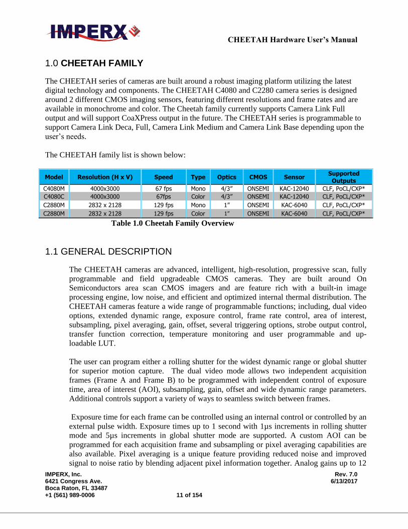
1.0 CHEETAH FAMILY
The CHEETAH series of cameras are built around a robust imaging platform utilizing the latest
digital technology and components. The CHEETAH C4080 and C2280 camera series is designed
around 2 different CMOS imaging sensors, featuring different resolutions and frame rates and are
available in monochrome and color. The Cheetah family currently supports Camera Link Full
output and will support CoaXPress output in the future. The CHEETAH series is programmable to
support Camera Link Deca, Full, Camera Link Medium and Camera Link Base depending upon the
user’s needs.
The CHEETAH family list is shown below:
Model Resolution (H x V) Speed Type Optics CMOS Sensor Supported
Outputs
C4080M 4000x3000 67 fps Mono 4/3” ONSEMI KAC-12040 CLF, PoCL/CXP*
C4080C 4000x3000 67fps Color 4/3” ONSEMI KAC-12040 CLF, PoCL/CXP*
C2880M 2832 x 2128 129 fps Mono 1” ONSEMI KAC-6040 CLF, PoCL/CXP*
C2880M 2832 x 2128 129 fps Color 1” ONSEMI KAC-6040 CLF, PoCL/CXP*
Table 1.0 Cheetah Family Overview
1.1 GENERAL DESCRIPTION
The CHEETAH cameras are advanced, intelligent, high-resolution, progressive scan, fully
programmable and field upgradeable CMOS cameras. They are built around On
Semiconductors area scan CMOS imagers and are feature rich with a built-in image
processing engine, low noise, and efficient and optimized internal thermal distribution. The
CHEETAH cameras feature a wide range of programmable functions; including, dual video
options, extended dynamic range, exposure control, frame rate control, area of interest,
subsampling, pixel averaging, gain, offset, several triggering options, strobe output control,
transfer function correction, temperature monitoring and user programmable and up-
loadable LUT.
The user can program either a rolling shutter for the widest dynamic range or global shutter
for superior motion capture. The dual video mode allows two independent acquisition
frames (Frame A and Frame B) to be programmed with independent control of exposure
time, area of interest (AOI), subsampling, gain, offset and wide dynamic range parameters.
Additional controls support a variety of ways to seamless switch between frames.
Exposure time for each frame can be controlled using an internal control or controlled by an
external pulse width. Exposure times up to 1 second with 1µs increments in rolling shutter
mode and 5µs increments in global shutter mode are supported. A custom AOI can be
programmed for each acquisition frame and subsampling or pixel averaging capabilities are
also available. Pixel averaging is a unique feature providing reduced noise and improved
signal to noise ratio by blending adjacent pixel information together. Analog gains up to 12
CHEETAH Hardware User’s Manual
IMPERX, Inc. Rev. 7.0 6421 Congress Ave. 6/13/2017 Boca Raton, FL 33487 +1 (561) 989-0006 12 of 154
dB (4x) in 12-bit digitization mode and 18 dB (8x) in 10-bit mode are available. Digital gain
controls allow further expansion of the low-end signal with 24dB (15.9x) of additional gain
available. The wide dynamic range capability features multi-integration times within one
frame period compressing bright areas into the available output range and extending the
visible dynamic range up to 100db (global shutter mode only) with up to 3 knee points.
A built-in Gamma correction and user-defined LUT capability optimizes the camera’s
dynamic range even further. Defective and hot pixel corrections can also be applied to
correct for pixels that are over-responding or under-responding. Auto-White Balance
(AWB) is available in color cameras to correct for color temperature. The cameras have a
Camera Link™ interface that includes 8/10/12 bits data transmission with two, four, eight or
ten output taps as well as camera control all on one or two cables. The cameras are fully
programmable via the Camera Link interface and support Power over Camera Link (PoCL).
The adaptability and flexibility of the camera allow it to be used in a wide and diverse range
of applications including machine vision, metrology high-definition imaging and
surveillance, medical and scientific imaging, intelligent transportation systems, aerial
imaging, character recognition, document processing and many more.

CHEETAH Hardware User’s Manual
IMPERX, Inc. Rev. 7.0 6421 Congress Ave. 6/13/2017 Boca Raton, FL 33487 +1 (561) 989-0006 13 of 154
1.2 MAIN CHEETAH FEATURES
Global shutter (GS) or rolling shutter (RS)
Monochrome or color
Large 4.7-micron pixels
Excellent near infrared (NIR) sensitivity
Ultra-low fixed pattern noise
Exceptional blooming suppression
Fast frame rates: 129 fps (C2880), 67 fps (C4080)
Dual Video Capability
o Independent control of resolution, gain, offset, pixel averaging, sub-sampling, area
of Interest (AOI) and WDR for two acquisition frames
o Seamless switching between frames
o Manual, auto or triggered frame switching
Extended Dynamic Range (WDR)
o 3 knee points, Piece-wise Linear
Color and monochrome pixel averaging (4x and 9x)
Sub-sampling up to 32x
Areas of Interest
Analog and Digital Gain Controls
Offset Control
Three selectable trigger sources: external, pulse generator or computer
Built-in pulse generator
Two programmable output strobes
Auto-white balance: once, static or tracking
Image Enhancements
o Horizontal and vertical flip
Two 12-bit look-up tables: one LUT pre-programmed with gamma 0.45.
Defective pixel correction, hot pixel correction
Two programmable external Inputs and two external outputs.
Camera Link Base, Medium, Full and Deca support, PoCL support
Temperature monitor
Field upgradeable firmware, LUT, DPC, HPC
CHEETAH Hardware User’s Manual
IMPERX, Inc. Rev. 7.0 6421 Congress Ave. 6/13/2017 Boca Raton, FL 33487 +1 (561) 989-0006 14 of 154
1.3 CHEETAH SPECIFICATIONS
1.3.1 General Information
A CMOS camera is an electronic device for converting light into an electrical signal.
The camera contains a light sensitive element CMOS (Charge Coupled Device) where
an electronic representation of the image is formed. The CMOS image sensor consists
of a two dimensional array of sensitive elements – silicon photodiodes, also known as
pixels. The photons falling on the CMOS surface create photoelectrons within the
pixels, where the number of photoelectrons is linearly proportional to the light level.
Although the number of electrons collected in each pixel is linearly proportional to the
light level and exposure time, the amount of electrons varies with the wavelength of
the incident light.
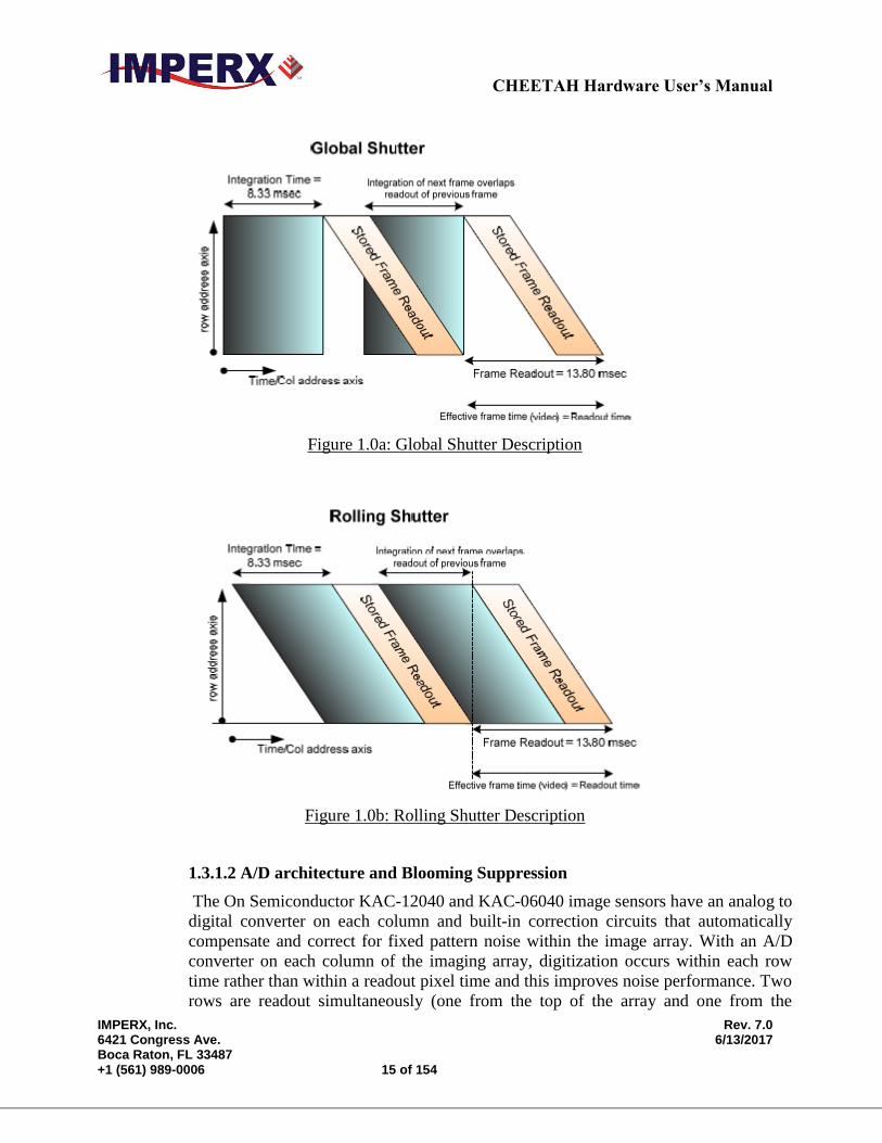
1.3.1.1 Rolling and Global Shutter Description
Cheetah C4080 and C2880 cameras support both global and rolling shutter readout
mode. In Global Shutter (GS) mode every pixel starts and stops integration at the same
time. This mode is excellent for clean capture of moving scenes without the need for a
mechanical shutter. When global shutter mode is used, all pixel data is stored in light
shielded regions within each pixel and held there until readout. (Figure 1.0a) In
Rolling Shutter (RS) mode each row of the image sensor is captured at a slightly
different time. (Figure 1.0b) This can cause distortions in the image, if an object is
moving very quickly and the integration time is short with respect to the frame readout
time. In rolling shutter mode, pixels in a row are cleared of charge, allowed to
integrate for the required exposure time and then the entire row is readout. The
resetting of each row ripples through the array and each row is exposed with a slight
time delay (equal to the line readout time) relative to the previous row. In RS mode,
the transistor within each pixel used to provide global shutter capability is used to
provide noise reduction.
CHEETAH Hardware User’s Manual
IMPERX, Inc. Rev. 7.0 6421 Congress Ave. 6/13/2017 Boca Raton, FL 33487 +1 (561) 989-0006 15 of 154
Figure 1.0a: Global Shutter Description
Figure 1.0b: Rolling Shutter Description
1.3.1.2 A/D architecture and Blooming Suppression
The On Semiconductor KAC-12040 and KAC-06040 image sensors have an analog to
digital converter on each column and built-in correction circuits that automatically
compensate and correct for fixed pattern noise within the image array. With an A/D
converter on each column of the imaging array, digitization occurs within each row
time rather than within a readout pixel time and this improves noise performance. Two
rows are readout simultaneously (one from the top of the array and one from the
CHEETAH Hardware User’s Manual
IMPERX, Inc. Rev. 7.0 6421 Congress Ave. 6/13/2017 Boca Raton, FL 33487 +1 (561) 989-0006 16 of 154
bottom of the array) during one line time readout. The camera takes care of all the
details of re-ordering the lines within frame grabber memory.
The A/D converter architecture allows the user to select between 8, 10 or 12-bit
digitization. The Cheetah C4080 supports both 10 and 12-bit digitization. In 12-bit
digitization mode, the A/D conversion time is longer than the minimum chip readout
time and this reduces maximum frame rates. In 10-bit digitization the A/D conversion
time is reduced increasing the maximum frame rate. The image sensor provides up to
eight LVDS readout banks and the time to readout one line from the image sensor is
less than the time necessary to output the data using Camera Link. The camera
compensates for this mismatch in data output rates by adding additional delay at the
end of each line.
Each pixel within the imaging array has extremely robust anti-blooming suppression
eliminating classic ‘black sun’ artifacts present in other CMOS imaging arrays. The
CMOS readout architecture also eliminates column smearing often seen in traditional
CCD image sensors under extremely bright exposure conditions.
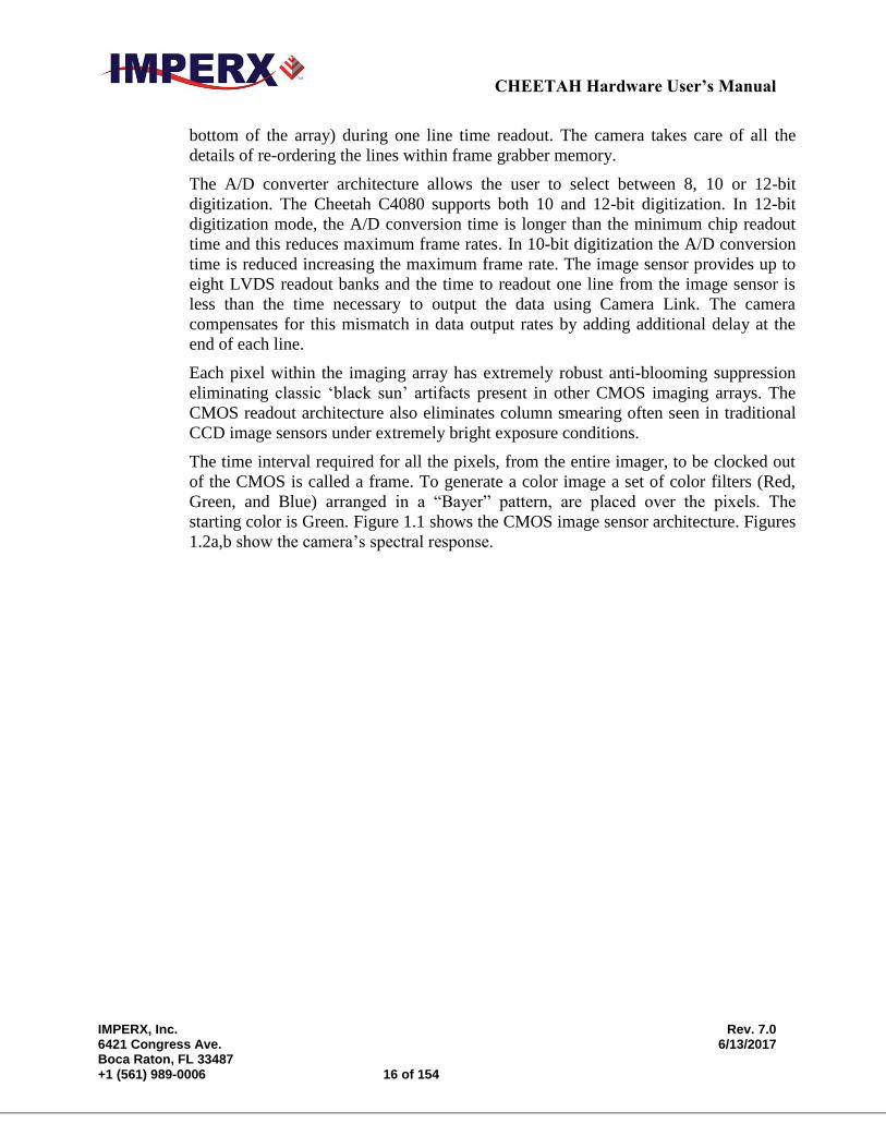
The time interval required for all the pixels, from the entire imager, to be clocked out
of the CMOS is called a frame. To generate a color image a set of color filters (Red,
Green, and Blue) arranged in a “Bayer” pattern, are placed over the pixels. The
starting color is Green. Figure 1.1 shows the CMOS image sensor architecture. Figures
1.2a,b show the camera’s spectral response.
CHEETAH Hardware User’s Manual
IMPERX, Inc. Rev. 7.0 6421 Congress Ave. 6/13/2017 Boca Raton, FL 33487 +1 (561) 989-0006 17 of 154
Figure 1.1: CMOS image sensor architecture
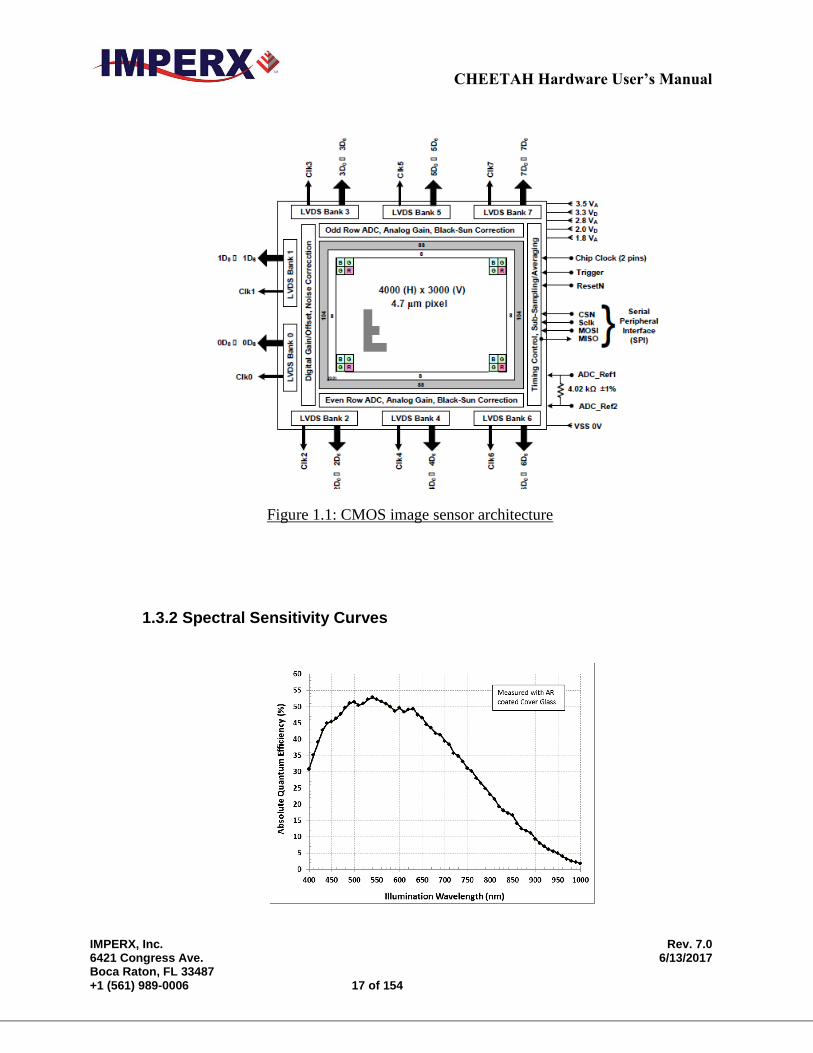
1.3.2 Spectral Sensitivity Curves
CHEETAH Hardware User’s Manual
IMPERX, Inc. Rev. 7.0 6421 Congress Ave. 6/13/2017 Boca Raton, FL 33487 +1 (561) 989-0006 18 of 154
Figure 1.2a: KAC-XX040 CMOS mono spectral response.
(Monochrome with the cover glass)
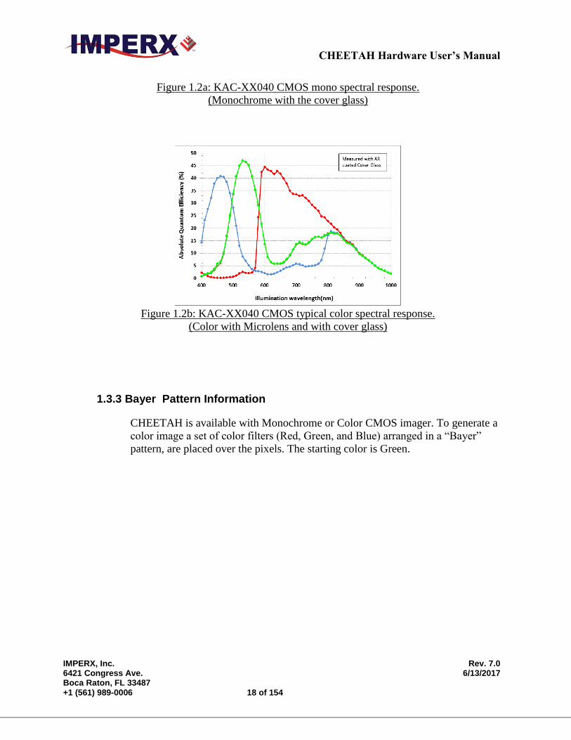
Figure 1.2b: KAC-XX040 CMOS typical color spectral response.
(Color with Microlens and with cover glass)
1.3.3 Bayer Pattern Information
CHEETAH is available with Monochrome or Color CMOS imager. To generate a
color image a set of color filters (Red, Green, and Blue) arranged in a “Bayer”
pattern, are placed over the pixels. The starting color is Green.
CHEETAH Hardware User’s Manual
IMPERX, Inc. Rev. 7.0 6421 Congress Ave. 6/13/2017 Boca Raton, FL 33487 +1 (561) 989-0006 19 of 154
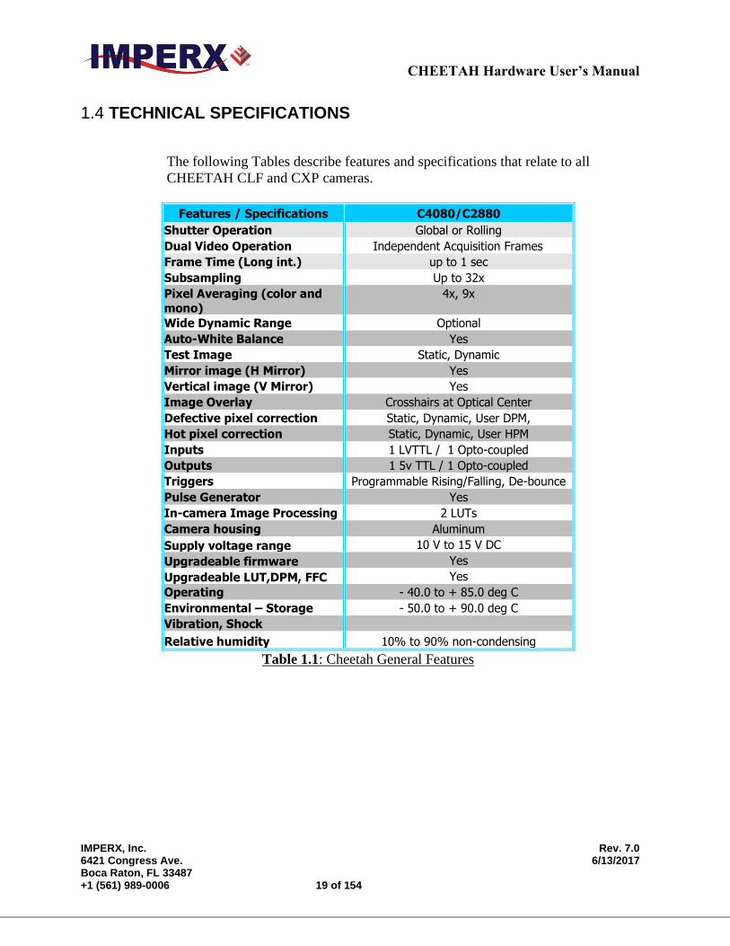
1.4 TECHNICAL SPECIFICATIONS
The following Tables describe features and specifications that relate to all
CHEETAH CLF and CXP cameras.
Features / Specifications C4080/C2880
Shutter Operation Global or Rolling
Dual Video Operation Independent Acquisition Frames
Frame Time (Long int.) up to 1 sec
Subsampling Up to 32x
Pixel Averaging (color and
mono)
4x, 9x
Wide Dynamic Range Optional
Auto-White Balance Yes
Test Image Static, Dynamic
Mirror image (H Mirror) Yes
Vertical image (V Mirror) Yes
Image Overlay Crosshairs at Optical Center
Defective pixel correction Static, Dynamic, User DPM,
Hot pixel correction Static, Dynamic, User HPM
Inputs 1 LVTTL / 1 Opto-coupled
Outputs 1 5v TTL / 1 Opto-coupled
Triggers Programmable Rising/Falling, De-bounce
Pulse Generator Yes
In-camera Image Processing 2 LUTs
Camera housing Aluminum
Supply voltage range 10 V to 15 V DC
Upgradeable firmware Yes
Upgradeable LUT,DPM, FFC Yes
Operating - 40.0 to + 85.0 deg C
Environmental – Storage - 50.0 to + 90.0 deg C
Vibration, Shock
Relative humidity 10% to 90% non-condensing
Table 1.1: Cheetah General Features
CHEETAH Hardware User’s Manual
IMPERX, Inc. Rev. 7.0 6421 Congress Ave. 6/13/2017 Boca Raton, FL 33487 +1 (561) 989-0006 20 of 154
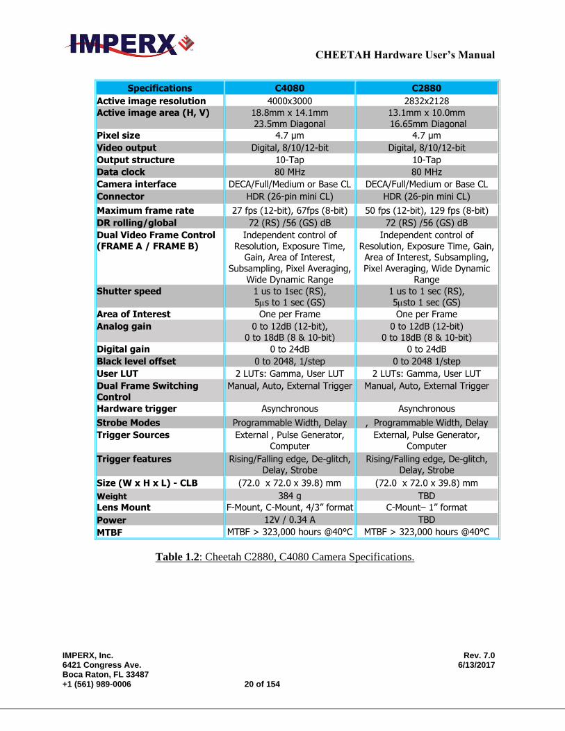
Specifications C4080 C2880
Active image resolution 4000x3000 2832x2128
Active image area (H, V) 18.8mm x 14.1mm
23.5mm Diagonal
13.1mm x 10.0mm
16.65mm Diagonal
Pixel size 4.7 μm 4.7 μm
Video output Digital, 8/10/12-bit Digital, 8/10/12-bit
Output structure 10-Tap 10-Tap
Data clock 80 MHz 80 MHz
Camera interface DECA/Full/Medium or Base CL DECA/Full/Medium or Base CL
Connector HDR (26-pin mini CL) HDR (26-pin mini CL)
Maximum frame rate 27 fps (12-bit), 67fps (8-bit) 50 fps (12-bit), 129 fps (8-bit)
DR rolling/global 72 (RS) /56 (GS) dB 72 (RS) /56 (GS) dB
Dual Video Frame Control
(FRAME A / FRAME B)
Independent control of
Resolution, Exposure Time, Gain, Area of Interest,
Subsampling, Pixel Averaging, Wide Dynamic Range
Independent control of
Resolution, Exposure Time, Gain, Area of Interest, Subsampling,
Pixel Averaging, Wide Dynamic Range
Shutter speed 1 us to 1sec (RS),
5s to 1 sec (GS)
1 us to 1 sec (RS),
5sto 1 sec (GS)
Area of Interest One per Frame One per Frame
Analog gain 0 to 12dB (12-bit),
0 to 18dB (8 & 10-bit)
0 to 12dB (12-bit)
0 to 18dB (8 & 10-bit)
Digital gain 0 to 24dB 0 to 24dB
Black level offset 0 to 2048, 1/step 0 to 2048 1/step
User LUT 2 LUTs: Gamma, User LUT 2 LUTs: Gamma, User LUT
Dual Frame Switching
Control
Manual, Auto, External Trigger Manual, Auto, External Trigger
Hardware trigger Asynchronous Asynchronous
Strobe Modes Programmable Width, Delay , Programmable Width, Delay
Trigger Sources External , Pulse Generator,
Computer
External, Pulse Generator,
Computer
Trigger features Rising/Falling edge, De-glitch, Delay, Strobe
Rising/Falling edge, De-glitch, Delay, Strobe
Size (W x H x L) - CLB (72.0 x 72.0 x 39.8) mm (72.0 x 72.0 x 39.8) mm
Weight 384 g TBD
Lens Mount F-Mount, C-Mount, 4/3” format C-Mount– 1” format
Power 12V / 0.34 A TBD
MTBF MTBF > 323,000 hours @40°C MTBF > 323,000 hours @40°C
Table 1.2: Cheetah C2880, C4080 Camera Specifications.
CHEETAH Hardware User’s Manual
IMPERX, Inc. Rev. 7.0 6421 Congress Ave. 6/13/2017 Boca Raton, FL 33487 +1 (561) 989-0006 21 of 154
1.5 CAMERA CONNECTIVITY
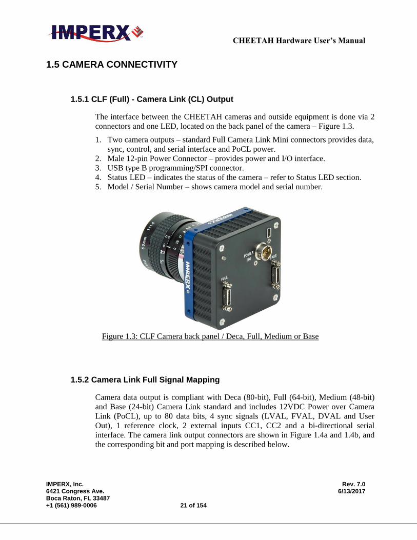
1.5.1 CLF (Full) - Camera Link (CL) Output
The interface between the CHEETAH cameras and outside equipment is done via 2
connectors and one LED, located on the back panel of the camera – Figure 1.3.
1. Two camera outputs – standard Full Camera Link Mini connectors provides data,
sync, control, and serial interface and PoCL power.
2. Male 12-pin Power Connector – provides power and I/O interface.
3. USB type B programming/SPI connector.
4. Status LED – indicates the status of the camera – refer to Status LED section.
5. Model / Serial Number – shows camera model and serial number.
Figure 1.3: CLF Camera back panel / Deca, Full, Medium or Base
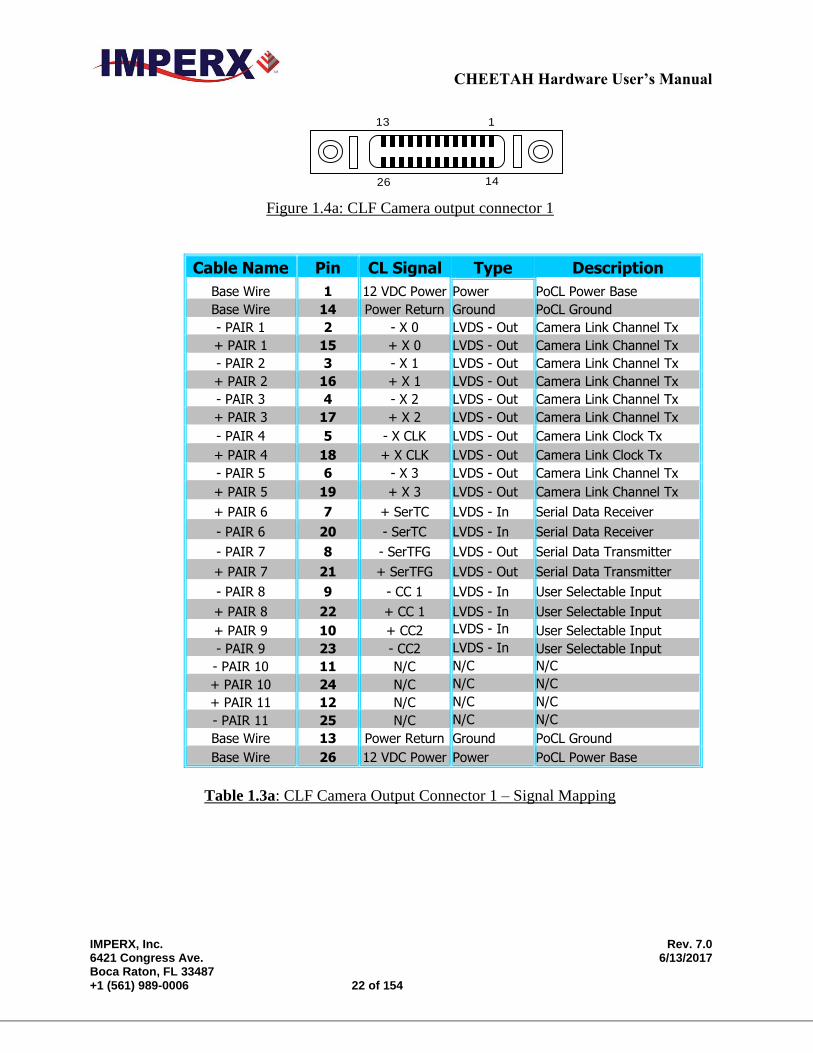
1.5.2 Camera Link Full Signal Mapping
Camera data output is compliant with Deca (80-bit), Full (64-bit), Medium (48-bit)
and Base (24-bit) Camera Link standard and includes 12VDC Power over Camera
Link (PoCL), up to 80 data bits, 4 sync signals (LVAL, FVAL, DVAL and User
Out), 1 reference clock, 2 external inputs CC1, CC2 and a bi-directional serial
interface. The camera link output connectors are shown in Figure 1.4a and 1.4b, and
the corresponding bit and port mapping is described below.
CHEETAH Hardware User’s Manual
IMPERX, Inc. Rev. 7.0 6421 Congress Ave. 6/13/2017 Boca Raton, FL 33487 +1 (561) 989-0006 22 of 154
1
14
13
26
Figure 1.4a: CLF Camera output connector 1
Cable Name Pin CL Signal Type Description
Base Wire 1 12 VDC Power Power PoCL Power Base
Base Wire 14 Power Return Ground PoCL Ground
- PAIR 1 2 - X 0 LVDS - Out Camera Link Channel Tx
+ PAIR 1 15 + X 0 LVDS - Out Camera Link Channel Tx
- PAIR 2 3 - X 1 LVDS - Out Camera Link Channel Tx
+ PAIR 2 16 + X 1 LVDS - Out Camera Link Channel Tx
- PAIR 3 4 - X 2 LVDS - Out Camera Link Channel Tx
+ PAIR 3 17 + X 2 LVDS - Out Camera Link Channel Tx
- PAIR 4 5 - X CLK LVDS - Out Camera Link Clock Tx
+ PAIR 4 18 + X CLK LVDS - Out Camera Link Clock Tx
- PAIR 5 6 - X 3 LVDS - Out Camera Link Channel Tx
+ PAIR 5 19 + X 3 LVDS - Out Camera Link Channel Tx
+ PAIR 6 7 + SerTC LVDS - In Serial Data Receiver
- PAIR 6 20 - SerTC LVDS - In Serial Data Receiver
- PAIR 7 8 - SerTFG LVDS - Out Serial Data Transmitter
+ PAIR 7 21 + SerTFG LVDS - Out Serial Data Transmitter
- PAIR 8 9 - CC 1 LVDS - In User Selectable Input
+ PAIR 8 22 + CC 1 LVDS - In User Selectable Input
+ PAIR 9 10 + CC2 LVDS - In User Selectable Input
- PAIR 9 23 - CC2 LVDS - In User Selectable Input
- PAIR 10 11 N/C N/C N/C
+ PAIR 10 24 N/C N/C N/C
+ PAIR 11 12 N/C N/C N/C
- PAIR 11 25 N/C N/C N/C
Base Wire 13 Power Return Ground PoCL Ground
Base Wire 26 12 VDC Power Power PoCL Power Base
Table 1.3a: CLF Camera Output Connector 1 – Signal Mapping
CHEETAH Hardware User’s Manual
IMPERX, Inc. Rev. 7.0 6421 Congress Ave. 6/13/2017 Boca Raton, FL 33487 +1 (561) 989-0006 23 of 154
1
14
13
26
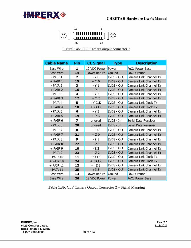
Figure 1.4b: CLF Camera output connector 2
Cable Name Pin CL Signal Type Description
Base Wire 1 12 VDC Power Power PoCL Power Base
Base Wire 14 Power Return Ground PoCL Ground
- PAIR 1 2 - Y 0 LVDS - Out Camera Link Channel Tx
+ PAIR 1 15 + Y 0 LVDS - Out Camera Link Channel Tx
- PAIR 2 3 - Y 1 LVDS - Out Camera Link Channel Tx
+ PAIR 2 16 + Y 1 LVDS - Out Camera Link Channel Tx
- PAIR 3 4 - Y 2 LVDS - Out Camera Link Channel Tx
+ PAIR 3 17 + Y 2 LVDS - Out Camera Link Channel Tx
- PAIR 4 5 - Y CLK LVDS - Out Camera Link Clock Tx
+ PAIR 4 18 + Y CLK LVDS - Out Camera Link Clock Tx
- PAIR 5 6 - Y 3 LVDS - Out Camera Link Channel Tx
+ PAIR 5 19 + Y 3 LVDS - Out Camera Link Channel Tx
+ PAIR 6 7 unused LVDS - In Serial Data Receiver
- PAIR 6 20 unused LVDS - In Serial Data Receiver
- PAIR 7 8 - Z 0 LVDS - Out Camera Link Channel Tx
+ PAIR 7 21 + Z 0 LVDS - Out Camera Link Channel Tx
- PAIR 8 9 - Z 1 LVDS - Out Camera Link Channel Tx
+ PAIR 8 22 + Z 1 LVDS - Out Camera Link Channel Tx
+ PAIR 9 10 - Z 2 LVDS - Out Camera Link Channel Tx
- PAIR 9 23 + Z 2 LVDS - Out Camera Link Channel Tx
- PAIR 10 11 -Z CLK LVDS - Out Camera Link Clock Tx
+ PAIR 10 24 + Z CLK LVDS - Out Camera Link Clock Tx
+ PAIR 11 12 - Z 3 LVDS - Out Camera Link Channel Tx
- PAIR 11 25 +Z 3 LVDS - Out Camera Link Channel Tx
Base Wire 13 Power Return Ground PoCL Ground
Base Wire 26 12 VDC Power Power PoCL Power Base
Table 1.3b: CLF Camera Output Connector 2 – Signal Mapping
CHEETAH Hardware User’s Manual
IMPERX, Inc. Rev. 7.0 6421 Congress Ave. 6/13/2017 Boca Raton, FL 33487 +1 (561) 989-0006 24 of 154
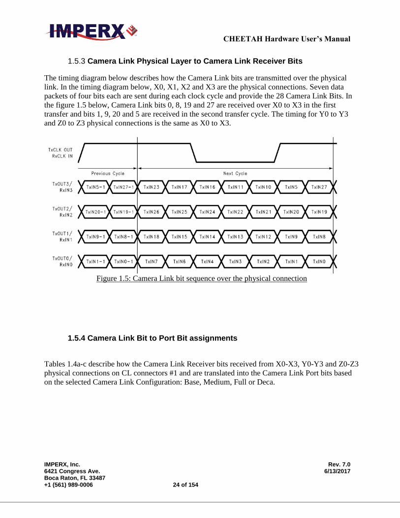
1.5.3 Camera Link Physical Layer to Camera Link Receiver Bits
The timing diagram below describes how the Camera Link bits are transmitted over the physical
link. In the timing diagram below, X0, X1, X2 and X3 are the physical connections. Seven data
packets of four bits each are sent during each clock cycle and provide the 28 Camera Link Bits. In
the figure 1.5 below, Camera Link bits 0, 8, 19 and 27 are received over X0 to X3 in the first
transfer and bits 1, 9, 20 and 5 are received in the second transfer cycle. The timing for Y0 to Y3
and Z0 to Z3 physical connections is the same as X0 to X3.
Figure 1.5: Camera Link bit sequence over the physical connection
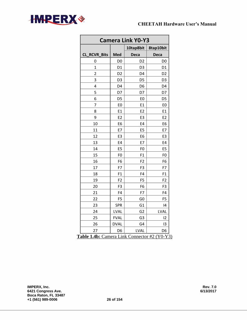
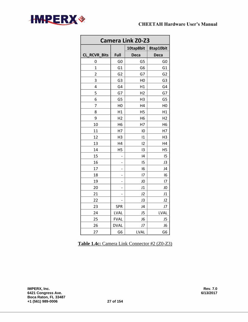
1.5.4 Camera Link Bit to Port Bit assignments
Tables 1.4a-c describe how the Camera Link Receiver bits received from X0-X3, Y0-Y3 and Z0-Z3
physical connections on CL connectors #1 and are translated into the Camera Link Port bits based
on the selected Camera Link Configuration: Base, Medium, Full or Deca.

CHEETAH Hardware User’s Manual
IMPERX, Inc. Rev. 7.0 6421 Congress Ave. 6/13/2017 Boca Raton, FL 33487 +1 (561) 989-0006 25 of 154
Camera Link X0-X3
CL_RCVR_Bits Base
10tap8bit 8tap10bit
Deca Deca
0 A0 A0 A0
1 A1 A1 A1
2 A2 A2 A2
3 A3 A3 A3
4 A4 A4 A4
5 A7 A5 A7
6 A5 A6 A5
7 B0 A7 B0
8 B1 B0 B1
9 B2 B1 B2
10 B6 B2 B6
11 B7 B3 B7
12 B3 B4 B3
13 B4 B5 B4
14 B5 B6 B5
15 C0 B7 C0
16 C6 C0 C6
17 C7 C1 C7
18 C1 C2 C1
19 C2 C3 C2
20 C3 C4 C3
21 C4 C5 C4
22 C5 C6 C5
23 SPR C7 I1
24 LVAL LVAL LVAL
25 FVAL FVAL FVAL
26 DVAL D0 I0
27 A6 D1 A6
Table 1.4a: Camera Link Connector #1 (X0-X3)
CHEETAH Hardware User’s Manual
IMPERX, Inc. Rev. 7.0 6421 Congress Ave. 6/13/2017 Boca Raton, FL 33487 +1 (561) 989-0006 26 of 154
Camera Link Y0-Y3
CL_RCVR_Bits Med
10tap8bit 8tap10bit
Deca Deca
0 D0 D2 D0
1 D1 D3 D1
2 D2 D4 D2
3 D3 D5 D3
4 D4 D6 D4
5 D7 D7 D7
6 D5 E0 D5
7 E0 E1 E0
8 E1 E2 E1
9 E2 E3 E2
10 E6 E4 E6
11 E7 E5 E7
12 E3 E6 E3
13 E4 E7 E4
14 E5 F0 E5
15 F0 F1 F0
16 F6 F2 F6
17 F7 F3 F7
18 F1 F4 F1
19 F2 F5 F2
20 F3 F6 F3
21 F4 F7 F4
22 F5 G0 F5
23 SPR G1 I4
24 LVAL G2 LVAL
25 FVAL G3 I2
26 DVAL G4 I3
27 D6 LVAL D6
Table 1.4b: Camera Link Connector #2 (Y0-Y3)
CHEETAH Hardware User’s Manual
IMPERX, Inc. Rev. 7.0 6421 Congress Ave. 6/13/2017 Boca Raton, FL 33487 +1 (561) 989-0006 27 of 154
Camera Link Z0-Z3
CL_RCVR_Bits Full
10tap8bit 8tap10bit
Deca Deca
0 G0 G5 G0
1 G1 G6 G1
2 G2 G7 G2
3 G3 H0 G3
4 G4 H1 G4
5 G7 H2 G7
6 G5 H3 G5
7 H0 H4 H0
8 H1 H5 H1
9 H2 H6 H2
10 H6 H7 H6
11 H7 I0 H7
12 H3 I1 H3
13 H4 I2 H4
14 H5 I3 H5
15 - I4 I5
16 - I5 J3
17 - I6 J4
18 - I7 I6
19 - J0 I7
20 - J1 J0
21 - J2 J1
22 - J3 J2
23 SPR J4 J7
24 LVAL J5 LVAL
25 FVAL J6 J5
26 DVAL J7 J6
27 G6 LVAL G6
Table 1.4c: Camera Link Connector #2 (Z0-Z3)
CHEETAH Hardware User’s Manual
IMPERX, Inc. Rev. 7.0 6421 Congress Ave. 6/13/2017 Boca Raton, FL 33487 +1 (561) 989-0006 28 of 154
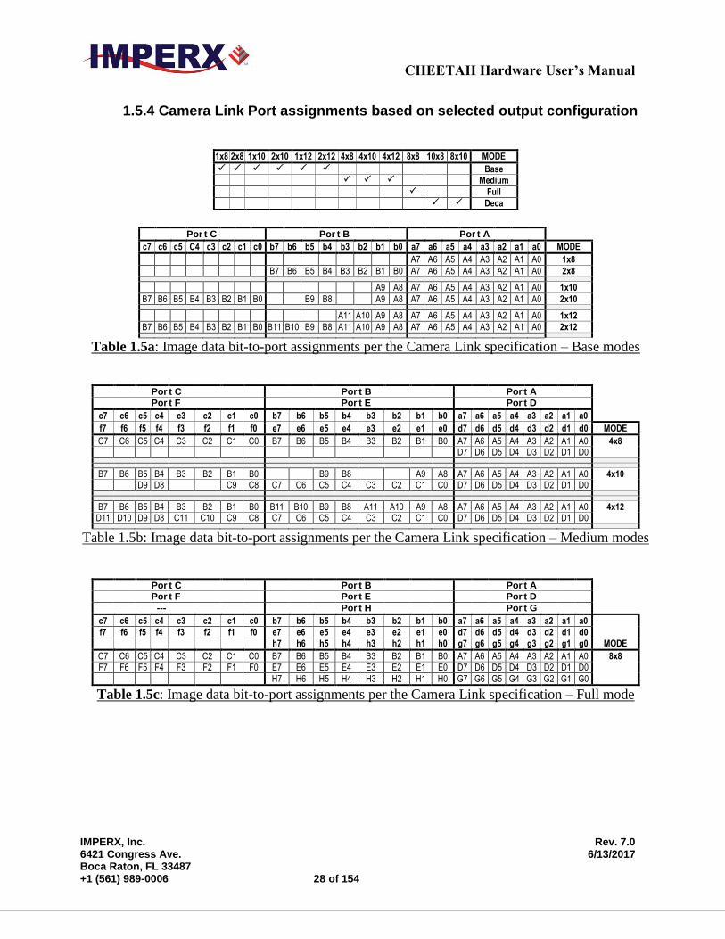
1.5.4 Camera Link Port assignments based on selected output configuration
1x8 2x8 1x10 2x10 1x12 2x12 4x8 4x10 4x12 8x8 10x8 8x10 MODE
Base
Medium
Full
Deca
Por t C Por t B Por t A
c7 c6 c5 C4 c3 c2 c1 c0 b7 b6 b5 b4 b3 b2 b1 b0 a7 a6 a5 a4 a3 a2 a1 a0 MODE
A7 A6 A5 A4 A3 A2 A1 A0 1x8
B7 B6 B5 B4 B3 B2 B1 B0 A7 A6 A5 A4 A3 A2 A1 A0 2x8
A9 A8 A7 A6 A5 A4 A3 A2 A1 A0 1x10
B7 B6 B5 B4 B3 B2 B1 B0 B9 B8 A9 A8 A7 A6 A5 A4 A3 A2 A1 A0 2x10
A11 A10 A9 A8 A7 A6 A5 A4 A3 A2 A1 A0 1x12
B7 B6 B5 B4 B3 B2 B1 B0 B11 B10 B9 B8 A11 A10 A9 A8 A7 A6 A5 A4 A3 A2 A1 A0 2x12
Table 1.5a: Image data bit-to-port assignments per the Camera Link specification – Base modes
Por t C Por t B Por t A
Por t F Por t E Por t D
c7 c6 c5 c4 c3 c2 c1 c0 b7 b6 b5 b4 b3 b2 b1 b0 a7 a6 a5 a4 a3 a2 a1 a0
f7 f6 f5 f4 f3 f2 f1 f0 e7 e6 e5 e4 e3 e2 e1 e0 d7 d6 d5 d4 d3 d2 d1 d0 MODE
C7 C6 C5 C4 C3 C2 C1 C0 B7 B6 B5 B4 B3 B2 B1 B0 A7 A6 A5 A4 A3 A2 A1 A0 4x8 D7 D6 D5 D4 D3 D2 D1 D0
B7 B6 B5 B4 B3 B2 B1 B0 B9 B8 A9 A8 A7 A6 A5 A4 A3 A2 A1 A0 4x10 D9 D8 C9 C8 C7 C6 C5 C4 C3 C2 C1 C0 D7 D6 D5 D4 D3 D2 D1 D0
B7 B6 B5 B4 B3 B2 B1 B0 B11 B10 B9 B8 A11 A10 A9 A8 A7 A6 A5 A4 A3 A2 A1 A0 4x12 D11 D10 D9 D8 C11 C10 C9 C8 C7 C6 C5 C4 C3 C2 C1 C0 D7 D6 D5 D4 D3 D2 D1 D0
Table 1.5b: Image data bit-to-port assignments per the Camera Link specification – Medium modes
Por t C Por t B Por t A Por t F Por t E Por t D
--- Por t H Por t G
c7 c6 c5 c4 c3 c2 c1 c0 b7 b6 b5 b4 b3 b2 b1 b0 a7 a6 a5 a4 a3 a2 a1 a0
f7 f6 f5 f4 f3 f2 f1 f0 e7 e6 e5 e4 e3 e2 e1 e0 d7 d6 d5 d4 d3 d2 d1 d0
h7 h6 h5 h4 h3 h2 h1 h0 g7 g6 g5 g4 g3 g2 g1 g0 MODE
C7 C6 C5 C4 C3 C2 C1 C0 B7 B6 B5 B4 B3 B2 B1 B0 A7 A6 A5 A4 A3 A2 A1 A0 8x8
F7 F6 F5 F4 F3 F2 F1 F0 E7 E6 E5 E4 E3 E2 E1 E0 D7 D6 D5 D4 D3 D2 D1 D0
H7 H6 H5 H4 H3 H2 H1 H0 G7 G6 G5 G4 G3 G2 G1 G0
Table 1.5c: Image data bit-to-port assignments per the Camera Link specification – Full mode
CHEETAH Hardware User’s Manual
IMPERX, Inc. Rev. 7.0 6421 Congress Ave. 6/13/2017 Boca Raton, FL 33487 +1 (561) 989-0006 29 of 154
Por t C Por t B Por t A
Por t F Por t E Por t D
Por t I Por t H Por t G
--- --- Por t J
c7 c6 c5 c4 c3 c2 c1 c0 b7 b6 b5 b4 b3 b2 b1 b0 a7 a6 a5 a4 a3 a2 a1 a0
f7 f6 f5 f4 f3 f2 f1 f0 e7 e6 e5 e4 e3 e2 e1 e0 d7 d6 d5 d4 d3 d2 d1 d0
i7 i6 i5 i4 i3 i2 i1 i0 h7 h6 h5 h4 h3 h2 h1 h0 g7 g6 g5 g4 g3 g2 g1 g0
j7 j6 j5 j4 j3 j2 j1 j0 MODE
C7 C6 C5 C4 C3 C2 C1 C0 B7 B6 B5 B4 B3 B2 B1 B0 A7 A6 A5 A4 A3 A2 A1 A0 10x8
F7 F6 F5 F4 F3 F2 F1 F0 E7 E6 E5 E4 E3 E2 E1 E0 D7 D6 D5 D4 D3 D2 D1 D0
I7 I6 I5 I4 I3 I2 I1 I0 H7 H6 H5 H4 H3 H2 H1 H0 G7 G6 G5 G4 G3 G2 G1 G0
J7 J6 J5 J4 J3 J2 J1 J0
C9 C8 C7 C6 C5 C4 C3 C2 B9 B8 B7 B6 B5 B4 B3 B2 A9 A8 A7 A6 A5 A4 A3 A2 8x10
F9 F8 F7 F6 F5 F4 F3 F2 E9 E8 E7 E6 E5 E4 E3 E2 D9 D8 D7 D6 D5 D4 D3 D2
D1 D0 C1 C0 B1 B0 A1 A0 H9 H8 H7 H6 H5 H4 H3 H2 G9 G8 G7 G6 G5 G4 G3 G2
H1 H0 G1 G0 F1 F0 E1 E0
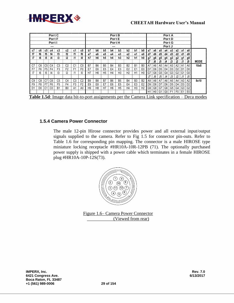
Table 1.5d: Image data bit-to-port assignments per the Camera Link specification – Deca modes
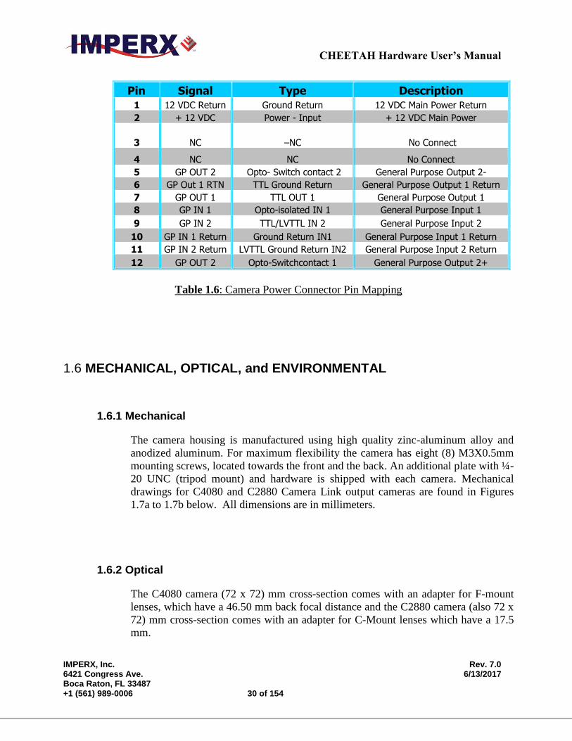
1.5.4 Camera Power Connector
The male 12-pin Hirose connector provides power and all external input/output
signals supplied to the camera. Refer to Fig 1.5 for connector pin-outs. Refer to
Table 1.6 for corresponding pin mapping. The connector is a male HIROSE type
miniature locking receptacle #HR10A-10R-12PB (71). The optionally purchased
power supply is shipped with a power cable which terminates in a female HIROSE
plug #HR10A-10P-12S(73).
Figure 1.6– Camera Power Connector
(Viewed from rear)
CHEETAH Hardware User’s Manual
IMPERX, Inc. Rev. 7.0 6421 Congress Ave. 6/13/2017 Boca Raton, FL 33487 +1 (561) 989-0006 30 of 154
Pin Signal Type Description
1 12 VDC Return Ground Return 12 VDC Main Power Return
2 + 12 VDC Power - Input + 12 VDC Main Power
3 NC –NC No Connect
4 NC NC No Connect
5 GP OUT 2 Opto- Switch contact 2 General Purpose Output 2-
6 GP Out 1 RTN TTL Ground Return General Purpose Output 1 Return
7 GP OUT 1 TTL OUT 1 General Purpose Output 1
8 GP IN 1 Opto-isolated IN 1 General Purpose Input 1
9 GP IN 2 TTL/LVTTL IN 2 General Purpose Input 2
10 GP IN 1 Return Ground Return IN1 General Purpose Input 1 Return
11 GP IN 2 Return LVTTL Ground Return IN2 General Purpose Input 2 Return
12 GP OUT 2 Opto-Switchcontact 1 General Purpose Output 2+
Table 1.6: Camera Power Connector Pin Mapping
1.6 MECHANICAL, OPTICAL, and ENVIRONMENTAL
1.6.1 Mechanical
The camera housing is manufactured using high quality zinc-aluminum alloy and
anodized aluminum. For maximum flexibility the camera has eight (8) M3X0.5mm
mounting screws, located towards the front and the back. An additional plate with ¼-
20 UNC (tripod mount) and hardware is shipped with each camera. Mechanical
drawings for C4080 and C2880 Camera Link output cameras are found in Figures
1.7a to 1.7b below. All dimensions are in millimeters.
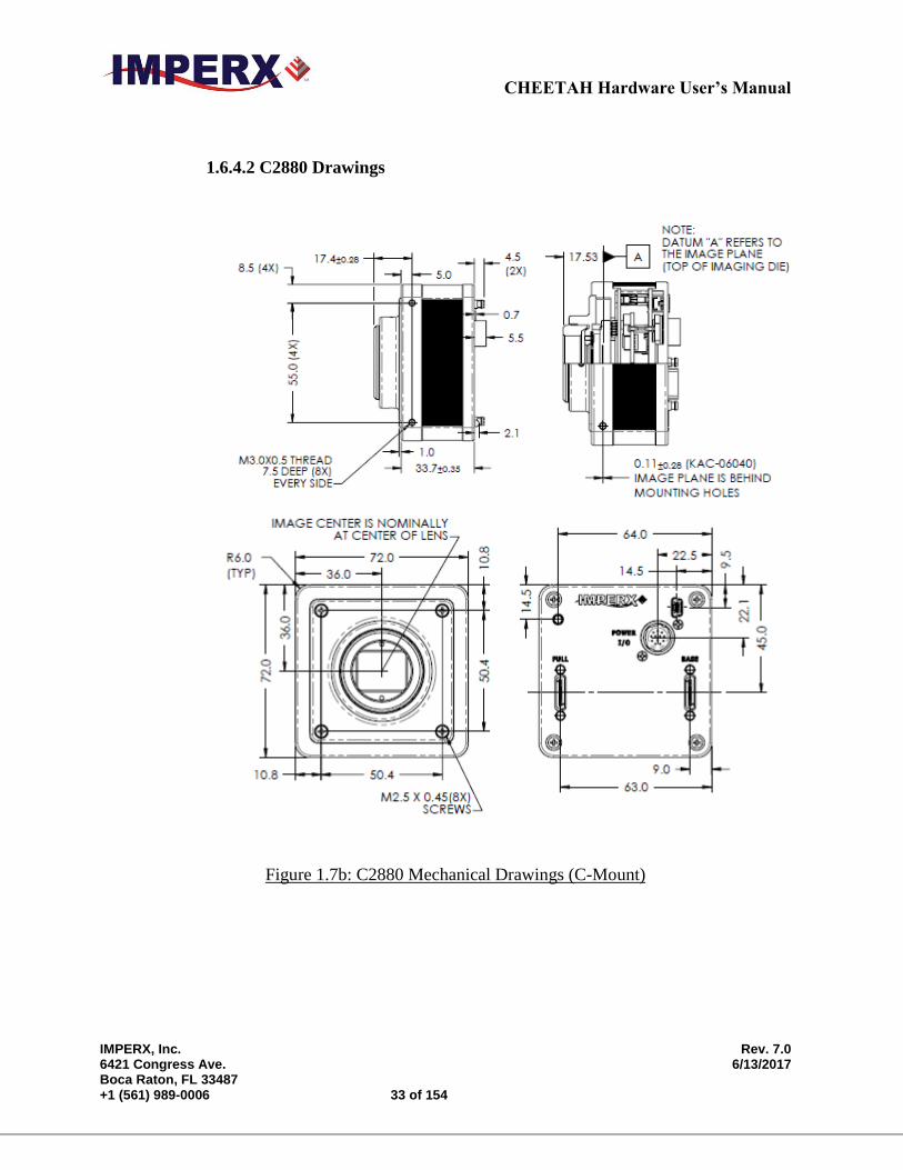
1.6.2 Optical
The C4080 camera (72 x 72) mm cross-section comes with an adapter for F-mount
lenses, which have a 46.50 mm back focal distance and the C2880 camera (also 72 x
72) mm cross-section comes with an adapter for C-Mount lenses which have a 17.5
mm.
CHEETAH Hardware User’s Manual
IMPERX, Inc. Rev. 7.0 6421 Congress Ave. 6/13/2017 Boca Raton, FL 33487 +1 (561) 989-0006 31 of 154
The camera performance and signal to noise ratio depends on the illumination
(amount of light) reaching the sensor and the exposure time. Always try to balance
these two factors. Unnecessarily long exposure will increase the amount of noise and
thus decrease the signal to noise ratio.
The cameras are very sensitive in the IR spectral region. All color cameras have and
IR cut-off filter installed. The monochrome cameras are without IR filter. If
necessary, an IR filter (1 mm thickness or less) can be inserted under the front lens
bezel.
CAUTION NOTE
1. Avoid direct exposure to a high intensity light source (such as a laser beam).
This may damage the camera optical sensor!
2. Avoid foreign particles on the surface of the imager.
1.6.3 Environmental
The camera is designed to operate from -400 to 850 C in a dry environment. The
relative humidity should not exceed 80% non-condensing. Always keep the camera
as cool as possible. Always allow sufficient time for temperature equalization, if the
camera was kept below 00 C!
The camera should be stored in a dry environment with the temperature ranging
from -500 to + 900 C.
CAUTION NOTE
1. Avoid direct exposure to moisture and liquids. The camera housing is not
hermetically sealed and any exposure to liquids may damage the camera
electronics!
2. Avoid operating in an environment without any air circulation, in close
proximity to an intensive heat source, strong magnetic or electric fields.
3. Avoid touching or cleaning the front surface of the optical sensor. If the sensor
needs to be cleaned, use soft lint free cloth and an optical cleaning fluid. Do not
use methylated alcohol!
CHEETAH Hardware User’s Manual
IMPERX, Inc. Rev. 7.0 6421 Congress Ave. 6/13/2017 Boca Raton, FL 33487 +1 (561) 989-0006 32 of 154
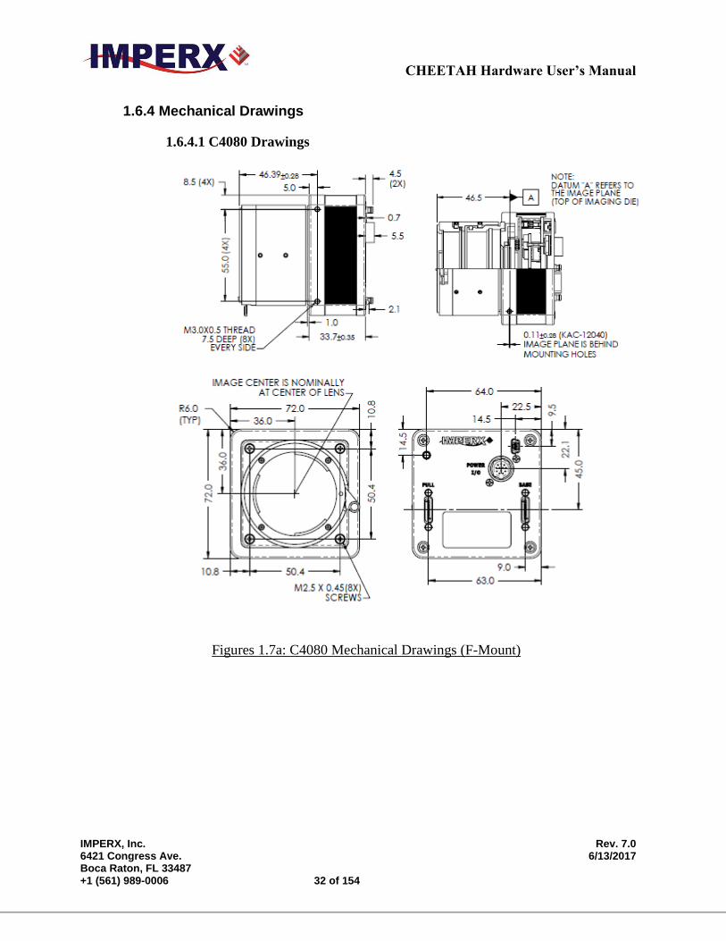
1.6.4 Mechanical Drawings
1.6.4.1 C4080 Drawings
Figures 1.7a: C4080 Mechanical Drawings (F-Mount)
CHEETAH Hardware User’s Manual
IMPERX, Inc. Rev. 7.0 6421 Congress Ave. 6/13/2017 Boca Raton, FL 33487 +1 (561) 989-0006 33 of 154
1.6.4.2 C2880 Drawings
Figure 1.7b: C2880 Mechanical Drawings (C-Mount)
CHEETAH Hardware User’s Manual
IMPERX, Inc. Rev. 7.0 6421 Congress Ave. 6/13/2017 Boca Raton, FL 33487 +1 (561) 989-0006 34 of 154
Chapter 2 – Camera Features
Camera Features
This chapter discusses the camera’s features and their use.
CHEETAH Hardware User’s Manual
IMPERX, Inc. Rev. 7.0 6421 Congress Ave. 6/13/2017 Boca Raton, FL 33487 +1 (561) 989-0006 35 of 154
2.1 DUAL VIDEO (FRAME A / FRAME B)
2.1.1 Frame A / Frame B Description
The camera provides two user defined frames (Frame A and Frame B) and the ability
to switch seamlessly between the two frames either manually, automatically or
triggered. See Section 2.1.2 Frame Switching Options. The user can program each
frame with independent control of the following functions:
Exposure Time
Frame Period
Area of Interest (AOI)
Averaging
Subsampling
Gain
Offset
Wide Dynamic Range
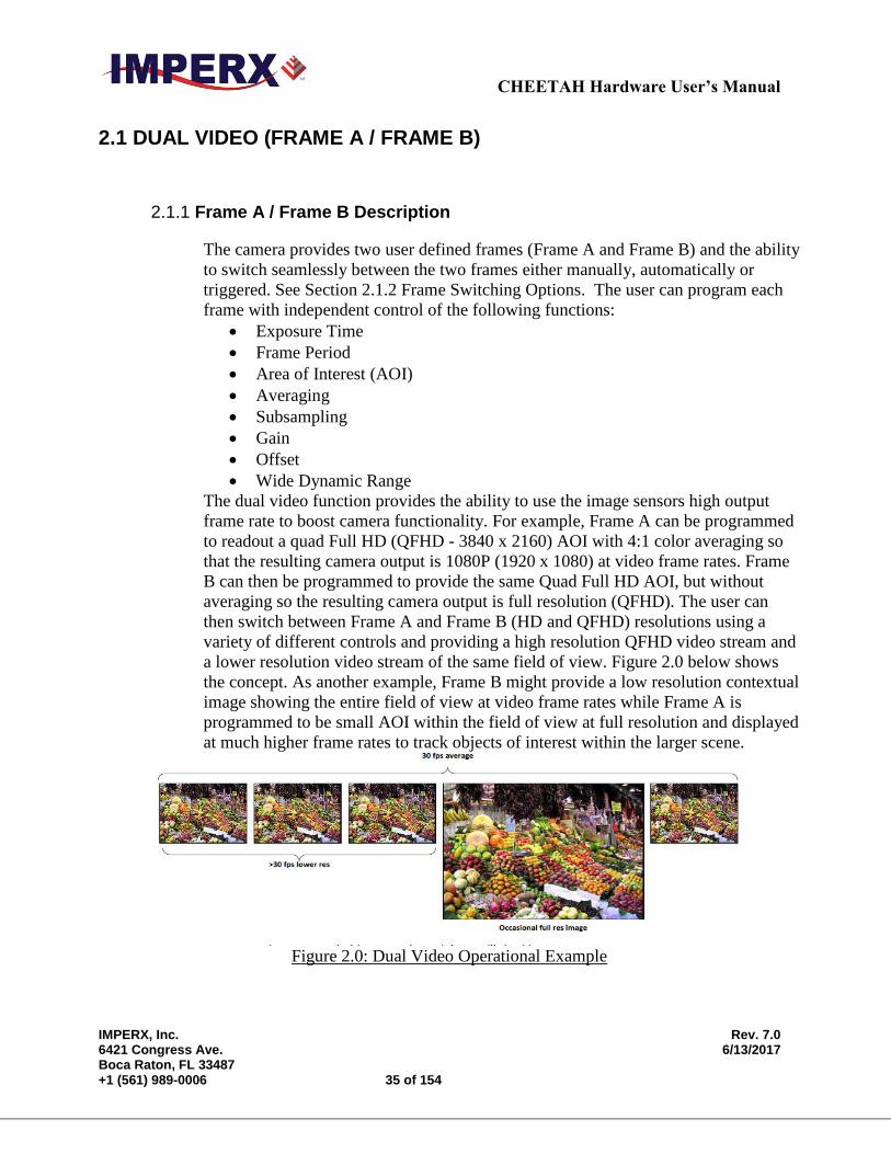
The dual video function provides the ability to use the image sensors high output
frame rate to boost camera functionality. For example, Frame A can be programmed
to readout a quad Full HD (QFHD - 3840 x 2160) AOI with 4:1 color averaging so
that the resulting camera output is 1080P (1920 x 1080) at video frame rates. Frame
B can then be programmed to provide the same Quad Full HD AOI, but without
averaging so the resulting camera output is full resolution (QFHD). The user can
then switch between Frame A and Frame B (HD and QFHD) resolutions using a
variety of different controls and providing a high resolution QFHD video stream and
a lower resolution video stream of the same field of view. Figure 2.0 below shows
the concept. As another example, Frame B might provide a low resolution contextual
image showing the entire field of view at video frame rates while Frame A is
programmed to be small AOI within the field of view at full resolution and displayed
at much higher frame rates to track objects of interest within the larger scene.
Figure 2.0: Dual Video Operational Example

CHEETAH Hardware User’s Manual
IMPERX, Inc. Rev. 7.0 6421 Congress Ave. 6/13/2017 Boca Raton, FL 33487 +1 (561) 989-0006 36 of 154
2.1.2 Dual Video: Frame A / Frame B Switching Options
The cameras provides several options for switching between Frame A and Frame B
(Dual Video).
Manual
Automatic
Triggered
Manual switching uses the computer software to switch between Frame A and
Frame B.
Automatic switching: The camera outputs a user defined number of frame As
(‘M’ frame As) followed by a user defined number of Frame Bs (‘N’ Frame Bs)
with this sequence repeated continuously. For example, the camera can be
programmed to output one Frame B for every sixty (60) Frame A’s. The camera
can be programmed to provide up to two hundred fifty-six (256) Frame “A’s”
followed by two hundred fifty-six (256) Frame “B’s”. The camera continues to
output ‘M’ Frame As followed by ‘N’ Frame Bs continuously.
Triggered Switching: There are two dual video triggered modes: Dual Video
and Dual Video Triggered.
Frame A / Frame B: With trigger enabled and in Frame A or Frame B
mode, the camera captures one frame of the selected Frame A or Frame
B and outputs it on each trigger.
Dual Video: With the trigger enabled and Dual Video selected, the
camera waits for trigger. On receipt of trigger, the camera outputs a user
selected number (‘M’) Frame As followed by a user selected number
(‘N’) Frame Bs then waits for trigger.
Dual Video Triggered: With trigger enabled and Dual Video Triggered
mode selected, the camera outputs Frame As continuously until a trigger
is received. Upon receipt of trigger, the camera outputs a user defined
number (‘N’) of Frame Bs then returns to outputting Frame As awaiting
the next trigger pulse. Valid Trigger sources as described in the Section
2.6: External Trigger.

CHEETAH Hardware User’s Manual
IMPERX, Inc. Rev. 7.0 6421 Congress Ave. 6/13/2017 Boca Raton, FL 33487 +1 (561) 989-0006 37 of 154
2.2 GLOBAL/ ROLLING SHUTTER
The camera supports both rolling and global shutter operational modes. In global shutter
operational mode, all lines (and all pixels) within the imaging array are reset at the same
time and then exposed. Readout follows exposure and lines are readout of the array
sequentially. In this mode, every pixel in the array is exposed during the same time period as
determined by the cameras exposure control setting. This is useful if an object within the
scene is moving, since all pixels within the array capture the image at the same instant in
time. Global shutter mode introduces more noise into the image and therefore is not as
sensitive as rolling shutter operation. In rolling shutter mode, each line with imaging array is
reset and exposed at a slightly different time period. If there is motion within the scene, this
can result in distortions to the object in motion, but the size of these distortions will vary
based on the readout rate of the camera and the speed of the object in motion. Many
applications are not sensitive to these slight distortions. Rolling shutter mode has much
more sensitivity as compared to global shutter mode and is useful in light starved
applications.
2.3 A/D DIGITIZATION
The user has the ability to select the ADC digitization level within the image sensor to trade-
off dynamic range for frame rate. When the user selects 12-bit digitization level, the
maximum frame rate is reduced to about 26 frames per second limited by the ADC settling
time. When the ADC selector is set to 10-bits, the A/D converter settling time is reduced
and the maximum camera output frame rate increases.
2.4 FRAME TIME CONTROL
2.4.1 Internal Line and Frame Time Control
The camera speed (frame rate) depends on the CMOS “read-out” time – the time
necessary to read all the pixels out of the CMOS imager. The frame rate can be
calculated using the following Formula 1.1:
Frame rate [fps] = 1 / read-out time [sec] (1.1)
The user can program the camera to run slower than the nominal speed preserving
the camera full resolution by extending the camera line time (the time required to
read one line out of the CMOS imager) and camera frame time (the time required to
read the entire frame out of the CMOS imager). Since the image sensor readout
CHEETAH Hardware User’s Manual
IMPERX, Inc. Rev. 7.0 6421 Congress Ave. 6/13/2017 Boca Raton, FL 33487 +1 (561) 989-0006 38 of 154
speed exceeds the Camera Link interface output rate, the camera automatically sets a
minimum line time based on the number of output taps and bit depth selected and
this sets the maximum frame rate consistent with the available bandwidth of the
output interface. If the frame grabber is losing data, increase the line time control to
match the frame grabber acquisition rate to the Cheetah output rate.
When the Fixed Frame Period control is enabled, the user can increase the frame
time from the camera determined minimum frame time to a maximum of 1 sec, with
a precision of ~ 1.0us. In this way, the user can reduce the camera output frame rate
to match the application requirements.
2.4.2 Camera Output Control
CHEETAH camera supports the following Camera Link Outputs: Single Tap, 2-Tap,
4-Tap, 8-Tap or 10-Tap Output. This corresponds to Base, Medium, Full or Deca
Output. These camera settings combined with the output bit-depth (8, 10 or 12-bit)
to control the total the interface bandwidth. The output interface clock speed for the
Cheetah Camera is 85-MHz (Camera Link Spec is 85 MHz maximum) It is
important to match the camera’s output to the frame grabber.
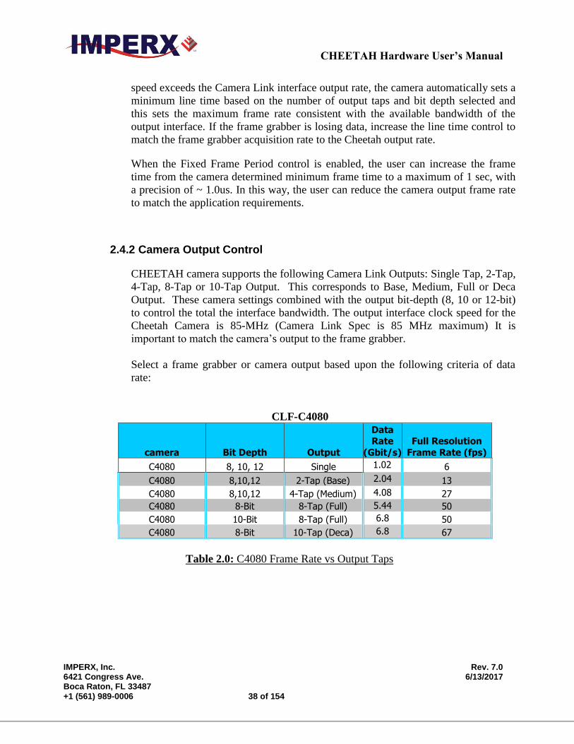
Select a frame grabber or camera output based upon the following criteria of data
rate:
CLF-C4080
camera Bit Depth Output
Data Rate
(Gbit/s)
Full Resolution
Frame Rate (fps)
C4080 8, 10, 12 Single 1.02 6
C4080 8,10,12 2-Tap (Base) 2.04 13
C4080 8,10,12 4-Tap (Medium) 4.08 27
C4080 8-Bit 8-Tap (Full) 5.44 50
C4080 10-Bit 8-Tap (Full) 6.8 50
C4080 8-Bit 10-Tap (Deca) 6.8 67
Table 2.0: C4080 Frame Rate vs Output Taps
CHEETAH Hardware User’s Manual
IMPERX, Inc. Rev. 7.0 6421 Congress Ave. 6/13/2017 Boca Raton, FL 33487 +1 (561) 989-0006 39 of 154
CLF-C2880
camera Bit Depth Output
Data
Rate (Gbit/s)
Full Resolution Frame Rate (fps)
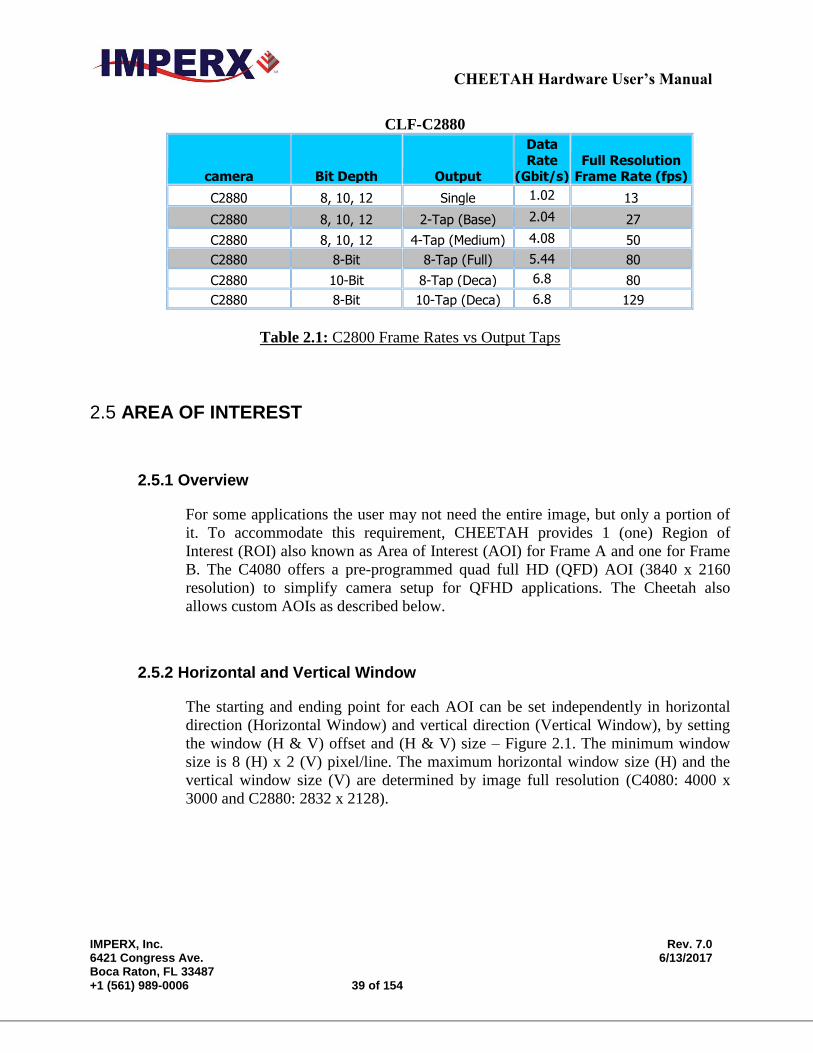
C2880 8, 10, 12 Single 1.02 13
C2880 8, 10, 12 2-Tap (Base) 2.04 27
C2880 8, 10, 12 4-Tap (Medium) 4.08 50
C2880 8-Bit 8-Tap (Full) 5.44 80
C2880 10-Bit 8-Tap (Deca) 6.8 80
C2880 8-Bit 10-Tap (Deca) 6.8 129
Table 2.1: C2800 Frame Rates vs Output Taps
2.5 AREA OF INTEREST
2.5.1 Overview
For some applications the user may not need the entire image, but only a portion of
it. To accommodate this requirement, CHEETAH provides 1 (one) Region of
Interest (ROI) also known as Area of Interest (AOI) for Frame A and one for Frame
B. The C4080 offers a pre-programmed quad full HD (QFD) AOI (3840 x 2160
resolution) to simplify camera setup for QFHD applications. The Cheetah also
allows custom AOIs as described below.
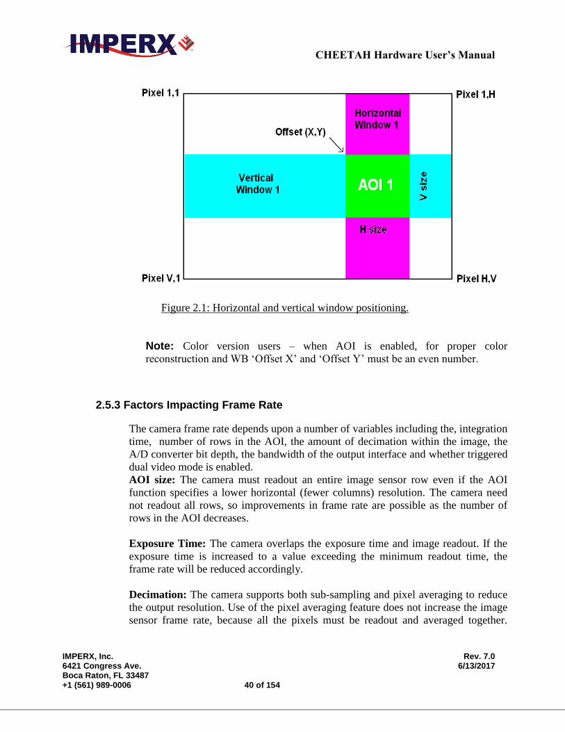
2.5.2 Horizontal and Vertical Window
The starting and ending point for each AOI can be set independently in horizontal
direction (Horizontal Window) and vertical direction (Vertical Window), by setting
the window (H & V) offset and (H & V) size – Figure 2.1. The minimum window
size is 8 (H) x 2 (V) pixel/line. The maximum horizontal window size (H) and the
vertical window size (V) are determined by image full resolution (C4080: 4000 x
3000 and C2880: 2832 x 2128).
CHEETAH Hardware User’s Manual
IMPERX, Inc. Rev. 7.0 6421 Congress Ave. 6/13/2017 Boca Raton, FL 33487 +1 (561) 989-0006 40 of 154
Figure 2.1: Horizontal and vertical window positioning.
Note: Color version users – when AOI is enabled, for proper color
reconstruction and WB ‘Offset X’ and ‘Offset Y’ must be an even number.
2.5.3 Factors Impacting Frame Rate
The camera frame rate depends upon a number of variables including the, integration
time, number of rows in the AOI, the amount of decimation within the image, the
A/D converter bit depth, the bandwidth of the output interface and whether triggered
dual video mode is enabled.
AOI size: The camera must readout an entire image sensor row even if the AOI
function specifies a lower horizontal (fewer columns) resolution. The camera need
not readout all rows, so improvements in frame rate are possible as the number of
rows in the AOI decreases.
Exposure Time: The camera overlaps the exposure time and image readout. If the
exposure time is increased to a value exceeding the minimum readout time, the
frame rate will be reduced accordingly.
Decimation: The camera supports both sub-sampling and pixel averaging to reduce
the output resolution. Use of the pixel averaging feature does not increase the image
sensor frame rate, because all the pixels must be readout and averaged together.
CHEETAH Hardware User’s Manual
IMPERX, Inc. Rev. 7.0 6421 Congress Ave. 6/13/2017 Boca Raton, FL 33487 +1 (561) 989-0006 41 of 154
However, sub-sampling decimation can offer a frame rate improvement by reducing
the number of rows readout from the image sensor.
A/D Bit Depth: The image sensor has an A/D converter on each column of the
image sensor and reads out two rows simultaneously. There is a finite time required
to reach convergence depending upon the A/D digitization level selected and this can
impact the maximum frame rate.
1) 8-bit digitization: ~9 micro-seconds
2) 10-bit digitization: ~9 micro-seconds
3) 12-bit digitization: ~20 micro-seconds
For example, if 12-bit digitization is selected, then two rows can be digitized in
20 micro-seconds. Since 3136 rows in the C4080 camera must be readout, digitizing
the entire image array consumes 31mS per frame and the frame rate is accordingly
limited.
Output Interface Bandwidth: The bandwidth of the output interface can also
impact the maximum achievable frame rate. For example, with Camera Link Base (2
taps selected) and with 10-bit digitization and 10-bit output mode selected, the
camera will output 13 full-frames per second limited by the output interface
bandwidth of 2.04 Gbps.
Triggered Dual Video Mode: The camera normally overlaps the exposure time
of one frame with the readout of the previous frame. In Triggered Dual Video Mode,
the exposure time and readout time are not overlapped and the total readout time is
the sum of the exposure and readout times.
2.5.3.1 AOI Frame Rate Examples
The Tables below describe resulting frame rate (FR) for various AOIs using Camera
Link Deca output. The frame grabber speed will impact results and values below
assume an x8 speed frame grabber. The camera will calculate and display the actual
frame rate at any horizontal and vertical window selection.
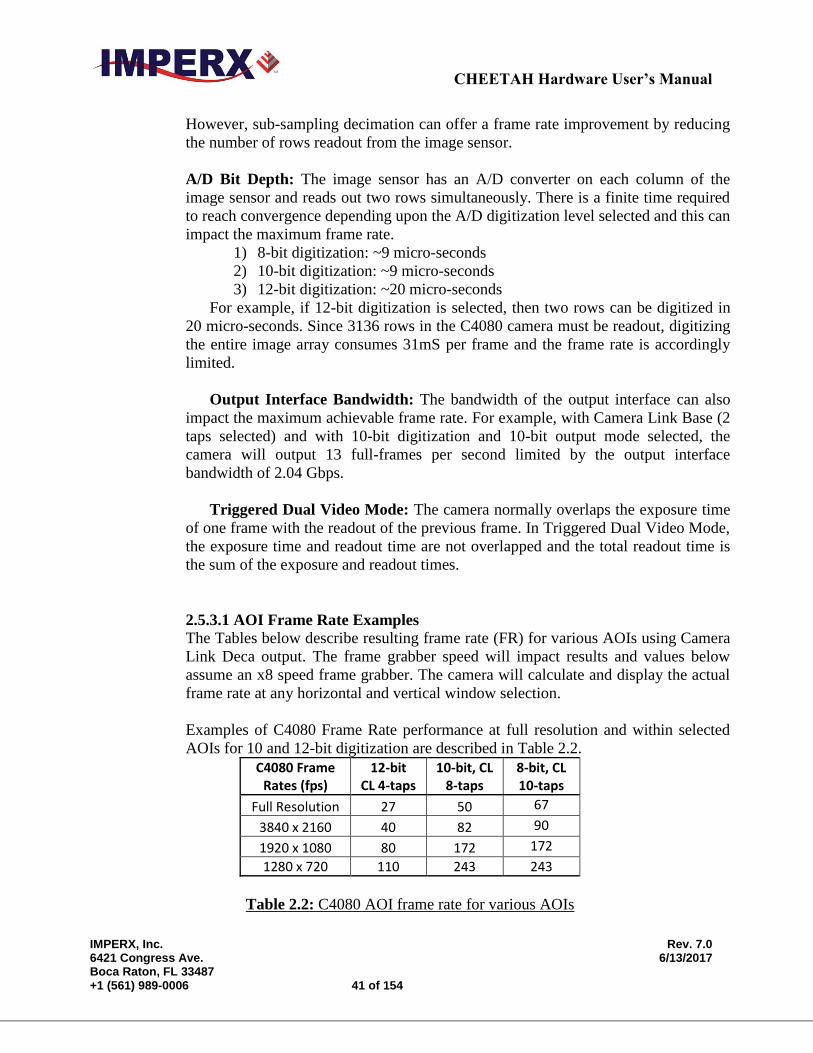
Examples of C4080 Frame Rate performance at full resolution and within selected
AOIs for 10 and 12-bit digitization are described in Table 2.2.
C4080 Frame Rates (fps)
12-bit CL 4-taps
10-bit, CL 8-taps
8-bit, CL 10-taps
Full Resolution 27 50 67
3840 x 2160 40 82 90
1920 x 1080 80 172 172
1280 x 720 110 243 243
Table 2.2: C4080 AOI frame rate for various AOIs
CHEETAH Hardware User’s Manual
IMPERX, Inc. Rev. 7.0 6421 Congress Ave. 6/13/2017 Boca Raton, FL 33487 +1 (561) 989-0006 42 of 154
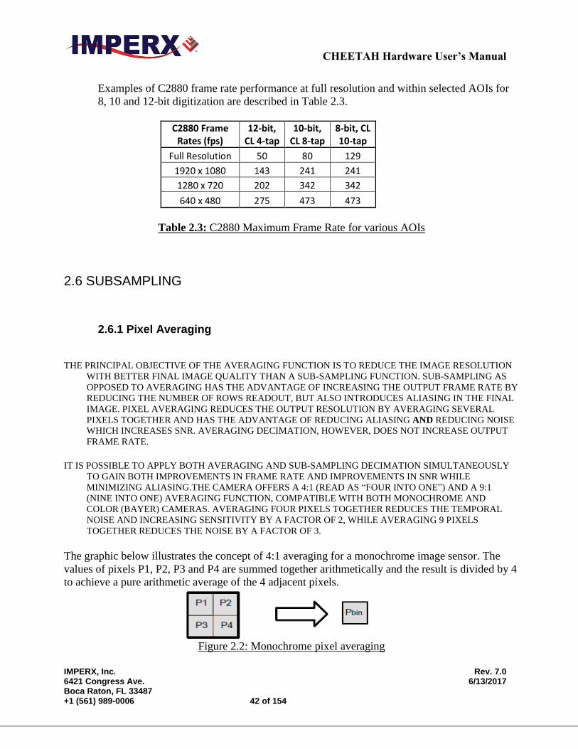
Examples of C2880 frame rate performance at full resolution and within selected AOIs for
8, 10 and 12-bit digitization are described in Table 2.3.
C2880 Frame Rates (fps)
12-bit, CL 4-tap
10-bit, CL 8-tap
8-bit, CL 10-tap
Full Resolution 50 80 129
1920 x 1080 143 241 241
1280 x 720 202 342 342
640 x 480 275 473 473
Table 2.3: C2880 Maximum Frame Rate for various AOIs
2.6 SUBSAMPLING
2.6.1 Pixel Averaging
THE PRINCIPAL OBJECTIVE OF THE AVERAGING FUNCTION IS TO REDUCE THE IMAGE RESOLUTION
WITH BETTER FINAL IMAGE QUALITY THAN A SUB-SAMPLING FUNCTION. SUB-SAMPLING AS
OPPOSED TO AVERAGING HAS THE ADVANTAGE OF INCREASING THE OUTPUT FRAME RATE BY
REDUCING THE NUMBER OF ROWS READOUT, BUT ALSO INTRODUCES ALIASING IN THE FINAL
IMAGE. PIXEL AVERAGING REDUCES THE OUTPUT RESOLUTION BY AVERAGING SEVERAL
PIXELS TOGETHER AND HAS THE ADVANTAGE OF REDUCING ALIASING AND REDUCING NOISE
WHICH INCREASES SNR. AVERAGING DECIMATION, HOWEVER, DOES NOT INCREASE OUTPUT
FRAME RATE.
IT IS POSSIBLE TO APPLY BOTH AVERAGING AND SUB-SAMPLING DECIMATION SIMULTANEOUSLY
TO GAIN BOTH IMPROVEMENTS IN FRAME RATE AND IMPROVEMENTS IN SNR WHILE
MINIMIZING ALIASING.THE CAMERA OFFERS A 4:1 (READ AS “FOUR INTO ONE”) AND A 9:1
(NINE INTO ONE) AVERAGING FUNCTION, COMPATIBLE WITH BOTH MONOCHROME AND
COLOR (BAYER) CAMERAS. AVERAGING FOUR PIXELS TOGETHER REDUCES THE TEMPORAL
NOISE AND INCREASING SENSITIVITY BY A FACTOR OF 2, WHILE AVERAGING 9 PIXELS
TOGETHER REDUCES THE NOISE BY A FACTOR OF 3.
The graphic below illustrates the concept of 4:1 averaging for a monochrome image sensor. The
values of pixels P1, P2, P3 and P4 are summed together arithmetically and the result is divided by 4
to achieve a pure arithmetic average of the 4 adjacent pixels.
Figure 2.2: Monochrome pixel averaging
CHEETAH Hardware User’s Manual
IMPERX, Inc. Rev. 7.0 6421 Congress Ave. 6/13/2017 Boca Raton, FL 33487 +1 (561) 989-0006 43 of 154
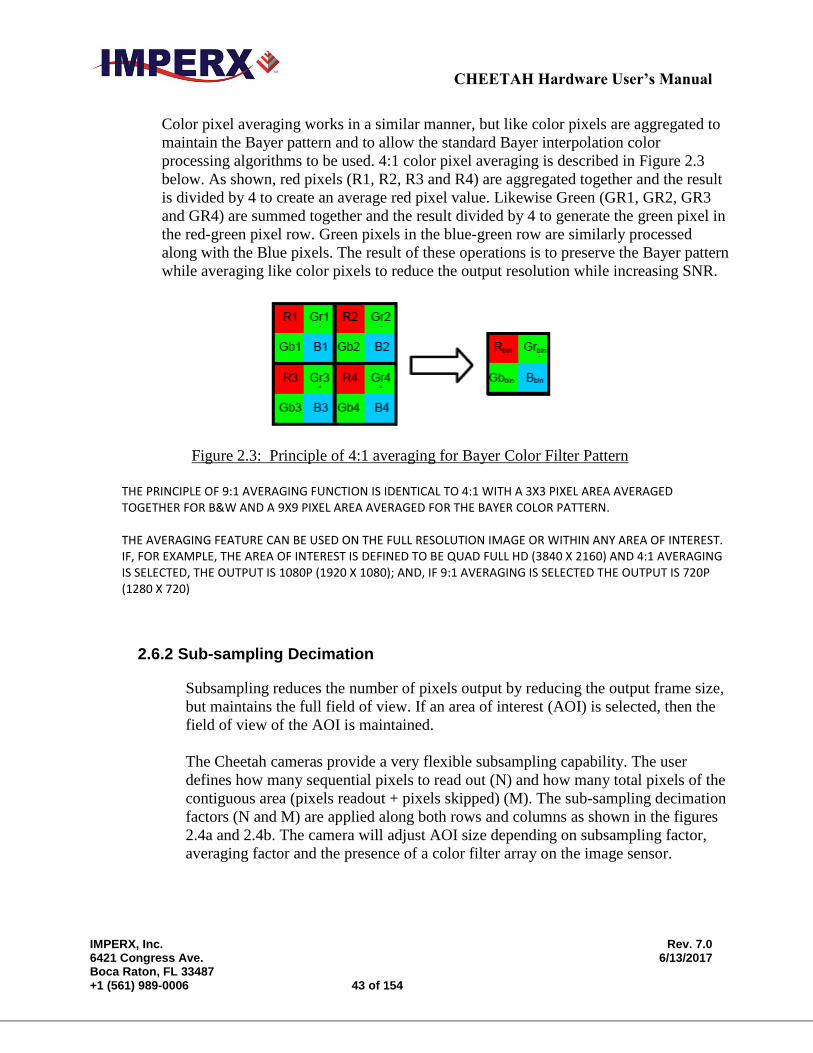
Color pixel averaging works in a similar manner, but like color pixels are aggregated to
maintain the Bayer pattern and to allow the standard Bayer interpolation color
processing algorithms to be used. 4:1 color pixel averaging is described in Figure 2.3
below. As shown, red pixels (R1, R2, R3 and R4) are aggregated together and the result
is divided by 4 to create an average red pixel value. Likewise Green (GR1, GR2, GR3
and GR4) are summed together and the result divided by 4 to generate the green pixel in
the red-green pixel row. Green pixels in the blue-green row are similarly processed
along with the Blue pixels. The result of these operations is to preserve the Bayer pattern
while averaging like color pixels to reduce the output resolution while increasing SNR.
Figure 2.3: Principle of 4:1 averaging for Bayer Color Filter Pattern
THE PRINCIPLE OF 9:1 AVERAGING FUNCTION IS IDENTICAL TO 4:1 WITH A 3X3 PIXEL AREA AVERAGED
TOGETHER FOR B&W AND A 9X9 PIXEL AREA AVERAGED FOR THE BAYER COLOR PATTERN. THE AVERAGING FEATURE CAN BE USED ON THE FULL RESOLUTION IMAGE OR WITHIN ANY AREA OF INTEREST.
IF, FOR EXAMPLE, THE AREA OF INTEREST IS DEFINED TO BE QUAD FULL HD (3840 X 2160) AND 4:1 AVERAGING IS SELECTED, THE OUTPUT IS 1080P (1920 X 1080); AND, IF 9:1 AVERAGING IS SELECTED THE OUTPUT IS 720P (1280 X 720)
2.6.2 Sub-sampling Decimation
Subsampling reduces the number of pixels output by reducing the output frame size,
but maintains the full field of view. If an area of interest (AOI) is selected, then the
field of view of the AOI is maintained.
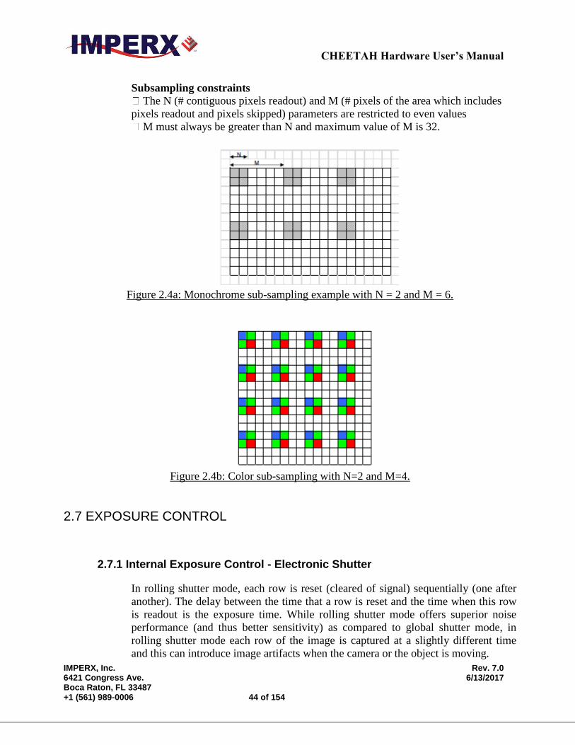
The Cheetah cameras provide a very flexible subsampling capability. The user
defines how many sequential pixels to read out (N) and how many total pixels of the
contiguous area (pixels readout + pixels skipped) (M). The sub-sampling decimation
factors (N and M) are applied along both rows and columns as shown in the figures
2.4a and 2.4b. The camera will adjust AOI size depending on subsampling factor,
averaging factor and the presence of a color filter array on the image sensor.
CHEETAH Hardware User’s Manual
IMPERX, Inc. Rev. 7.0 6421 Congress Ave. 6/13/2017 Boca Raton, FL 33487 +1 (561) 989-0006 44 of 154
Subsampling constraints The N (# contiguous pixels readout) and M (# pixels of the area which includes
pixels readout and pixels skipped) parameters are restricted to even values
M must always be greater than N and maximum value of M is 32.
Figure 2.4a: Monochrome sub-sampling example with N = 2 and M = 6.
Figure 2.4b: Color sub-sampling with N=2 and M=4.
2.7 EXPOSURE CONTROL
2.7.1 Internal Exposure Control - Electronic Shutter
In rolling shutter mode, each row is reset (cleared of signal) sequentially (one after
another). The delay between the time that a row is reset and the time when this row
is readout is the exposure time. While rolling shutter mode offers superior noise
performance (and thus better sensitivity) as compared to global shutter mode, in
rolling shutter mode each row of the image is captured at a slightly different time
and this can introduce image artifacts when the camera or the object is moving.

CHEETAH Hardware User’s Manual
IMPERX, Inc. Rev. 7.0 6421 Congress Ave. 6/13/2017 Boca Raton, FL 33487 +1 (561) 989-0006 45 of 154
In global shutter mode, all pixels in the array are reset at the same time, allowed to
collect signal during the exposure time and then readout sequentially. In this way, all
pixels capture the image during the same time period reducing any image artifacts
due to motion within the scene or the camera.
In free-running mode for both global and rolling shutter modes, the exposure time
overlaps the camera readout and is positioned to occur at the end of the frame
readout. The internal exposure control timer controls the exposure and is organized
into two counters: a line counter and a partial-line (sub-line) counter. In free-running
mode, frames are readout one after another so the maximum exposure time is equal
to the frame time. With no frame period control (Fixed Frame Period disabled), there
are 1146 lines per frame. Increasing the frame period using the Fixed Frame Period
control, adds additional lines (vertical blanking) to the frame readout increasing the
frame period and also increasing the maximum exposure time.
The exposure time can be computed by first converting the contents of the
Integration Lines counter and Integration Clocks (partial line) counter to time using
the following Frame A exposure time equation. (Frame B is the same, save the
register addresses have different values)
1) Exposure Time = (Integration Lines Counter [e.g., Reg 0728] x Line
Time[e.g., Reg 0710]) + (Integration Clocks (Partial Line) Counter[e.g., Reg
072C] x 6.25 nS ) [Note: all register values must be converted from hex to
decimal]
2) Line Time:
The line time can be computed in one of two ways:
A) Reading the contents of Line Time register (Reg: 0710 for Frame A or
Reg 0714 for Frame B), converting the hex number to decimal and
multiplying by 6.25nS
B) Measuring the frame time (GUI monitor screen) in free running mode
with the fixed frame period disabled and dividing by 1146 lines per
frame.
The minimum exposure in global shutter mode is 5 microseconds and 1
microsecond in rolling shutter mode.
As mentioned above, the exposure time cannot exceed the frame time. To increase
the exposure time, first increase the frame period to the maximum desired exposure
time and then adjust the exposure time.
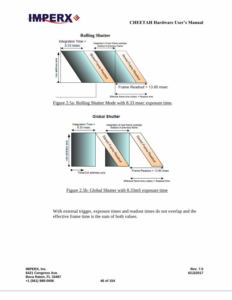
In free-running (non-triggered) operation, the camera overlaps the exposure and
readout times for both global and rolling shutter modes as shown in Figure 2.5a and
Figure 2.5b. Both figures show an 8.33mS exposure time overlapping with the 13.8
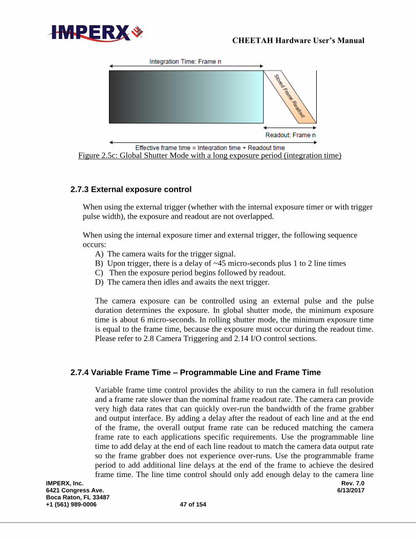
ms readout time. Figure 2.5c shows non-overlap exposure and readout in using an
Trigger.
CHEETAH Hardware User’s Manual
IMPERX, Inc. Rev. 7.0 6421 Congress Ave. 6/13/2017 Boca Raton, FL 33487 +1 (561) 989-0006 46 of 154
Rolling Shutter
Figure 2.5a: Rolling Shutter Mode with 8.33 msec exposure time.
Figure 2.5b: Global Shutter with 8.33mS exposure time
With external trigger, exposure times and readout times do not overlap and the
effective frame time is the sum of both values.
CHEETAH Hardware User’s Manual
IMPERX, Inc. Rev. 7.0 6421 Congress Ave. 6/13/2017 Boca Raton, FL 33487 +1 (561) 989-0006 47 of 154
Figure 2.5c: Global Shutter Mode with a long exposure period (integration time)
2.7.3 External exposure control
When using the external trigger (whether with the internal exposure timer or with trigger
pulse width), the exposure and readout are not overlapped.
When using the internal exposure timer and external trigger, the following sequence
occurs:
A) The camera waits for the trigger signal.
B) Upon trigger, there is a delay of ~45 micro-seconds plus 1 to 2 line times
C) Then the exposure period begins followed by readout.
D) The camera then idles and awaits the next trigger.
The camera exposure can be controlled using an external pulse and the pulse
duration determines the exposure. In global shutter mode, the minimum exposure
time is about 6 micro-seconds. In rolling shutter mode, the minimum exposure time
is equal to the frame time, because the exposure must occur during the readout time.
Please refer to 2.8 Camera Triggering and 2.14 I/O control sections.
2.7.4 Variable Frame Time – Programmable Line and Frame Time
Variable frame time control provides the ability to run the camera in full resolution
and a frame rate slower than the nominal frame readout rate. The camera can provide
very high data rates that can quickly over-run the bandwidth of the frame grabber
and output interface. By adding a delay after the readout of each line and at the end
of the frame, the overall output frame rate can be reduced matching the camera
frame rate to each applications specific requirements. Use the programmable line
time to add delay at the end of each line readout to match the camera data output rate
so the frame grabber does not experience over-runs. Use the programmable frame
period to add additional line delays at the end of the frame to achieve the desired
frame time. The line time control should only add enough delay to the camera line
CHEETAH Hardware User’s Manual
IMPERX, Inc. Rev. 7.0 6421 Congress Ave. 6/13/2017 Boca Raton, FL 33487 +1 (561) 989-0006 48 of 154
time to match the frame grabber data capture rate. Adding additional line delay will
decrease overall camera performance by increasing dark current within the image.
CAUTION NOTE
1. If the frame time is greater than 50ms the camera has to be kept still otherwise a
motion smear will appear on the image.
2.8 CAMERA TRIGGERING
2.8.1 Triggering Inputs
In the normal mode of operation, the camera is free running. Using the trigger mode
allows the camera to be synchronized to an external timing pulse. Trigger inputs can
be used to control the exposure times of Frame A and Frame B or can be used to
control Dual Video mode switching. In Dual Video mode, enabling the trigger input
causes the camera to output a user defined number of Frame As followed by a user
defined number of Frame Bs upon receipt of Trigger. In Dual Video Trigger mode,
the camera outputs Frame As until trigger is received and then outputs a user defined
number of Frame Bs.
There are three input modes available for external triggering – computer (CC),
internal (pulse generator), and external. Please note that the desired trigger input has
to be mapped to corresponding camera input. For more information, please refer to
Section 2.14: I/O Control.
- “External” – the camera receives the trigger signal coming from the connector
located on the back of the camera.
- “Computer” – the camera receives the trigger signal command from the CC
signals. .
- “Internal” – the camera has a built in programmable pulse generator – refer to
“Pulse Generator” section. In Internal triggering mode the camera receives the
trigger signal from the internal pulse generator.
2.8.2 Acquisition and Exposure Control
For each trigger input the user can set the trigger edge, and the de-bounce (de-glitch)
time/
1. “Triggering Edge” – the user can select the active triggering edge:
- “Rising” – the rising edge will be used for triggering
CHEETAH Hardware User’s Manual
IMPERX, Inc. Rev. 7.0 6421 Congress Ave. 6/13/2017 Boca Raton, FL 33487 +1 (561) 989-0006 49 of 154
- “Falling” – the falling edge will be used for triggering
2. “De-bounce” – the trigger inputs are de-bounced to prevent multiple triggering
from ringing triggering pulses. The user has eight choices of de-bounce interval:
- “Off” – no de-bounce (default)
- “10” s, “50” s, “100” s, “500” s de-bounce interval
- “1.0” ms, “5.0” ms, “10.0” ms de-bounce interval
- .
3. “Exposure Time” – the exposure for all frames can be set in two ways:
- “Pulse Width” – the trigger pulse width (duration) determines the exposure
subject to limitations. In GS mode, the minimum exposure is about 6 micro-
seconds. In RS mode, the minimum exposure is equal to the minimum frame
time.
- “Internal” – the camera internal exposure register determines the exposure.
CAUTION NOTE
1. The de-bounce interval MUST be smaller than the trigger pulse duration. Adjust
the interval accordingly.
2. When Triggering is enabled “Programmable Integration” is not active
2.8.3 Triggering modes
A. Exposure Control
When Trigger mode is enabled, the trigger can be used to control the integration
time of Frame A and / or Frame B using the Exposure Control Trigger Pulse Width
control. The trigger can also be used to switch between Frame A to Frame B in dual
video Trigger mode. The Exposure Control Trigger Pulse Width option is only
available when single video (either Frame A or Frame B) is selected. Control of the
exposure using the trigger pulse width is not available in Dual Video or Dual
Video Trigger modes.
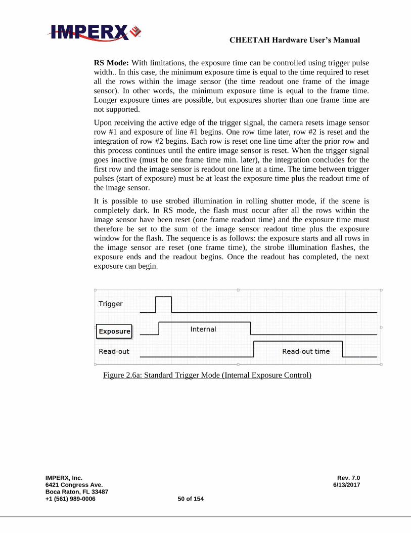
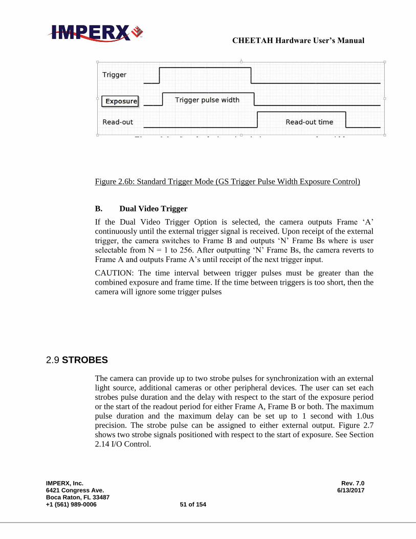
GS Mode: When the trigger pulse width is used to control the exposure time in GS
mode, the camera idles and waits for a trigger signal. Upon receiving the trigger
signal, the camera starts integration for the frame, completes the integration and the
image is readout. There is small delay between the trigger active edge and the
exposure start as shown in the figure below. The exposure time can be set manually
using the internal exposure register setting as shown in Figure 2.6a or set by the
duration of the trigger pulse as shown in Figure 2.6b. The minimum exposure time
using the trigger pulse width is 2 micro-seconds. Upon completing the readout, the
trigger cycle is completed and the camera idles awaiting the next trigger pulse.
CHEETAH Hardware User’s Manual
IMPERX, Inc. Rev. 7.0 6421 Congress Ave. 6/13/2017 Boca Raton, FL 33487 +1 (561) 989-0006 50 of 154
RS Mode: With limitations, the exposure time can be controlled using trigger pulse
width.. In this case, the minimum exposure time is equal to the time required to reset
all the rows within the image sensor (the time readout one frame of the image
sensor). In other words, the minimum exposure time is equal to the frame time.
Longer exposure times are possible, but exposures shorter than one frame time are
not supported.
Upon receiving the active edge of the trigger signal, the camera resets image sensor
row #1 and exposure of line #1 begins. One row time later, row #2 is reset and the
integration of row #2 begins. Each row is reset one line time after the prior row and
this process continues until the entire image sensor is reset. When the trigger signal
goes inactive (must be one frame time min. later), the integration concludes for the
first row and the image sensor is readout one line at a time. The time between trigger
pulses (start of exposure) must be at least the exposure time plus the readout time of
the image sensor.
It is possible to use strobed illumination in rolling shutter mode, if the scene is
completely dark. In RS mode, the flash must occur after all the rows within the
image sensor have been reset (one frame readout time) and the exposure time must
therefore be set to the sum of the image sensor readout time plus the exposure
window for the flash. The sequence is as follows: the exposure starts and all rows in
the image sensor are reset (one frame time), the strobe illumination flashes, the
exposure ends and the readout begins. Once the readout has completed, the next
exposure can begin.
Figure 2.6a: Standard Trigger Mode (Internal Exposure Control)
CHEETAH Hardware User’s Manual
IMPERX, Inc. Rev. 7.0 6421 Congress Ave. 6/13/2017 Boca Raton, FL 33487 +1 (561) 989-0006 51 of 154
Figure 2.6b: Standard Trigger Mode (GS Trigger Pulse Width Exposure Control)
B. Dual Video Trigger
If the Dual Video Trigger Option is selected, the camera outputs Frame ‘A’
continuously until the external trigger signal is received. Upon receipt of the external
trigger, the camera switches to Frame B and outputs ‘N’ Frame Bs where is user
selectable from N = 1 to 256. After outputting ‘N’ Frame Bs, the camera reverts to
Frame A and outputs Frame A’s until receipt of the next trigger input.
CAUTION: The time interval between trigger pulses must be greater than the
combined exposure and frame time. If the time between triggers is too short, then the
camera will ignore some trigger pulses
2.9 STROBES
The camera can provide up to two strobe pulses for synchronization with an external
light source, additional cameras or other peripheral devices. The user can set each
strobes pulse duration and the delay with respect to the start of the exposure period
or the start of the readout period for either Frame A, Frame B or both. The maximum
pulse duration and the maximum delay can be set up to 1 second with 1.0us
precision. The strobe pulse can be assigned to either external output. Figure 2.7
shows two strobe signals positioned with respect to the start of exposure. See Section
2.14 I/O Control.
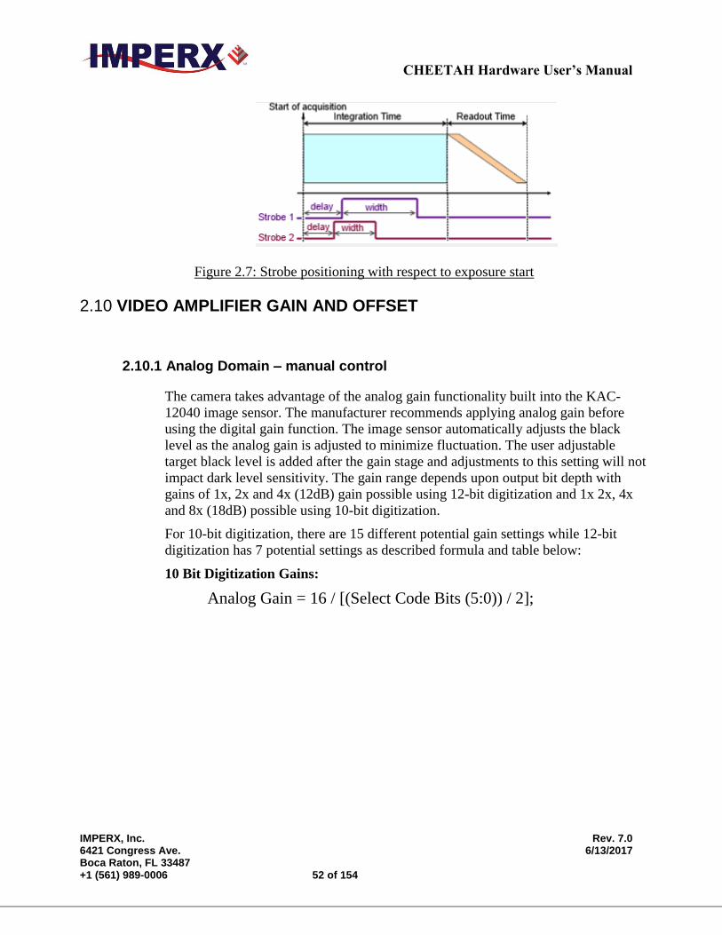
CHEETAH Hardware User’s Manual
IMPERX, Inc. Rev. 7.0 6421 Congress Ave. 6/13/2017 Boca Raton, FL 33487 +1 (561) 989-0006 52 of 154
Figure 2.7: Strobe positioning with respect to exposure start
2.10 VIDEO AMPLIFIER GAIN AND OFFSET
2.10.1 Analog Domain – manual control
The camera takes advantage of the analog gain functionality built into the KAC-
12040 image sensor. The manufacturer recommends applying analog gain before
using the digital gain function. The image sensor automatically adjusts the black
level as the analog gain is adjusted to minimize fluctuation. The user adjustable
target black level is added after the gain stage and adjustments to this setting will not
impact dark level sensitivity. The gain range depends upon output bit depth with
gains of 1x, 2x and 4x (12dB) gain possible using 12-bit digitization and 1x 2x, 4x
and 8x (18dB) possible using 10-bit digitization.
For 10-bit digitization, there are 15 different potential gain settings while 12-bit
digitization has 7 potential settings as described formula and table below:
10 Bit Digitization Gains:
Analog Gain = 16 / [(Select Code Bits (5:0)) / 2];
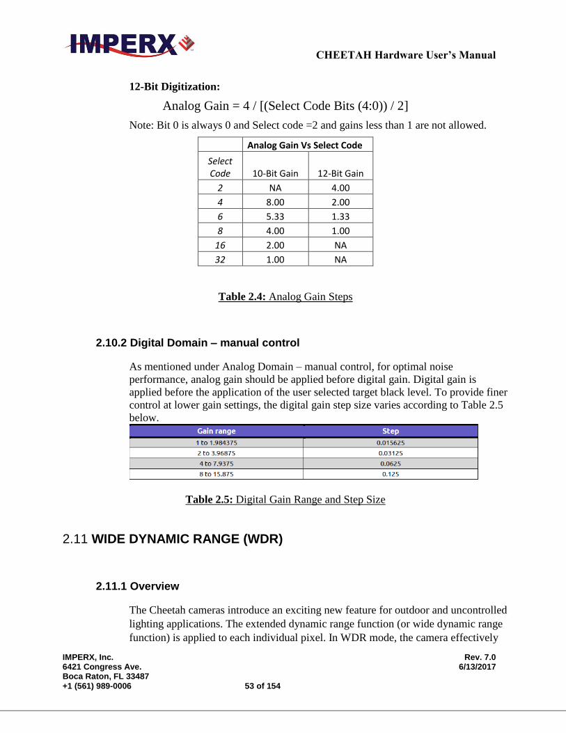
CHEETAH Hardware User’s Manual
IMPERX, Inc. Rev. 7.0 6421 Congress Ave. 6/13/2017 Boca Raton, FL 33487 +1 (561) 989-0006 53 of 154
12-Bit Digitization:
Analog Gain = 4 / [(Select Code Bits (4:0)) / 2]
Note: Bit 0 is always 0 and Select code =2 and gains less than 1 are not allowed.
Analog Gain Vs Select Code
Select Code 10-Bit Gain 12-Bit Gain
2 NA 4.00
4 8.00 2.00
6 5.33 1.33
8 4.00 1.00
16 2.00 NA
32 1.00 NA
Table 2.4: Analog Gain Steps
2.10.2 Digital Domain – manual control
As mentioned under Analog Domain – manual control, for optimal noise
performance, analog gain should be applied before digital gain. Digital gain is
applied before the application of the user selected target black level. To provide finer
control at lower gain settings, the digital gain step size varies according to Table 2.5
below.
Table 2.5: Digital Gain Range and Step Size
2.11 WIDE DYNAMIC RANGE (WDR)
2.11.1 Overview
The Cheetah cameras introduce an exciting new feature for outdoor and uncontrolled
lighting applications. The extended dynamic range function (or wide dynamic range
function) is applied to each individual pixel. In WDR mode, the camera effectively
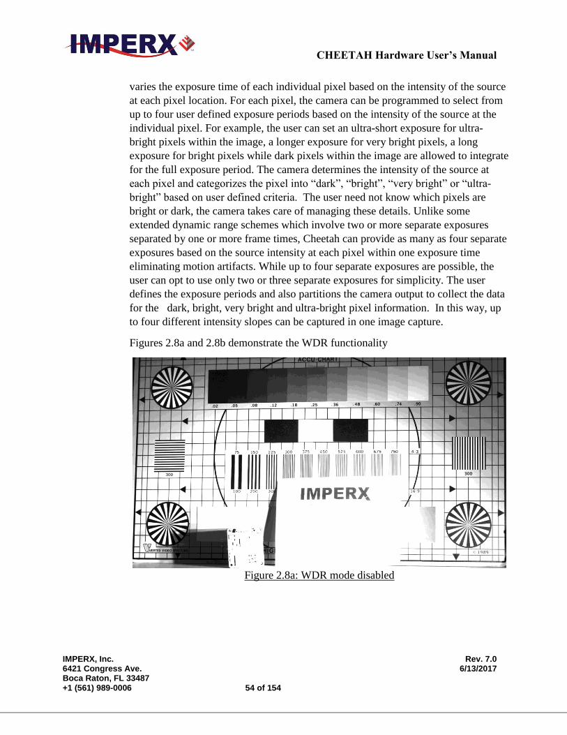
CHEETAH Hardware User’s Manual
IMPERX, Inc. Rev. 7.0 6421 Congress Ave. 6/13/2017 Boca Raton, FL 33487 +1 (561) 989-0006 54 of 154
varies the exposure time of each individual pixel based on the intensity of the source
at each pixel location. For each pixel, the camera can be programmed to select from
up to four user defined exposure periods based on the intensity of the source at the
individual pixel. For example, the user can set an ultra-short exposure for ultra-
bright pixels within the image, a longer exposure for very bright pixels, a long
exposure for bright pixels while dark pixels within the image are allowed to integrate
for the full exposure period. The camera determines the intensity of the source at
each pixel and categorizes the pixel into “dark”, “bright”, “very bright” or “ultra-
bright” based on user defined criteria. The user need not know which pixels are
bright or dark, the camera takes care of managing these details. Unlike some
extended dynamic range schemes which involve two or more separate exposures
separated by one or more frame times, Cheetah can provide as many as four separate
exposures based on the source intensity at each pixel within one exposure time
eliminating motion artifacts. While up to four separate exposures are possible, the
user can opt to use only two or three separate exposures for simplicity. The user
defines the exposure periods and also partitions the camera output to collect the data
for the dark, bright, very bright and ultra-bright pixel information. In this way, up
to four different intensity slopes can be captured in one image capture.
Figures 2.8a and 2.8b demonstrate the WDR functionality
Figure 2.8a: WDR mode disabled
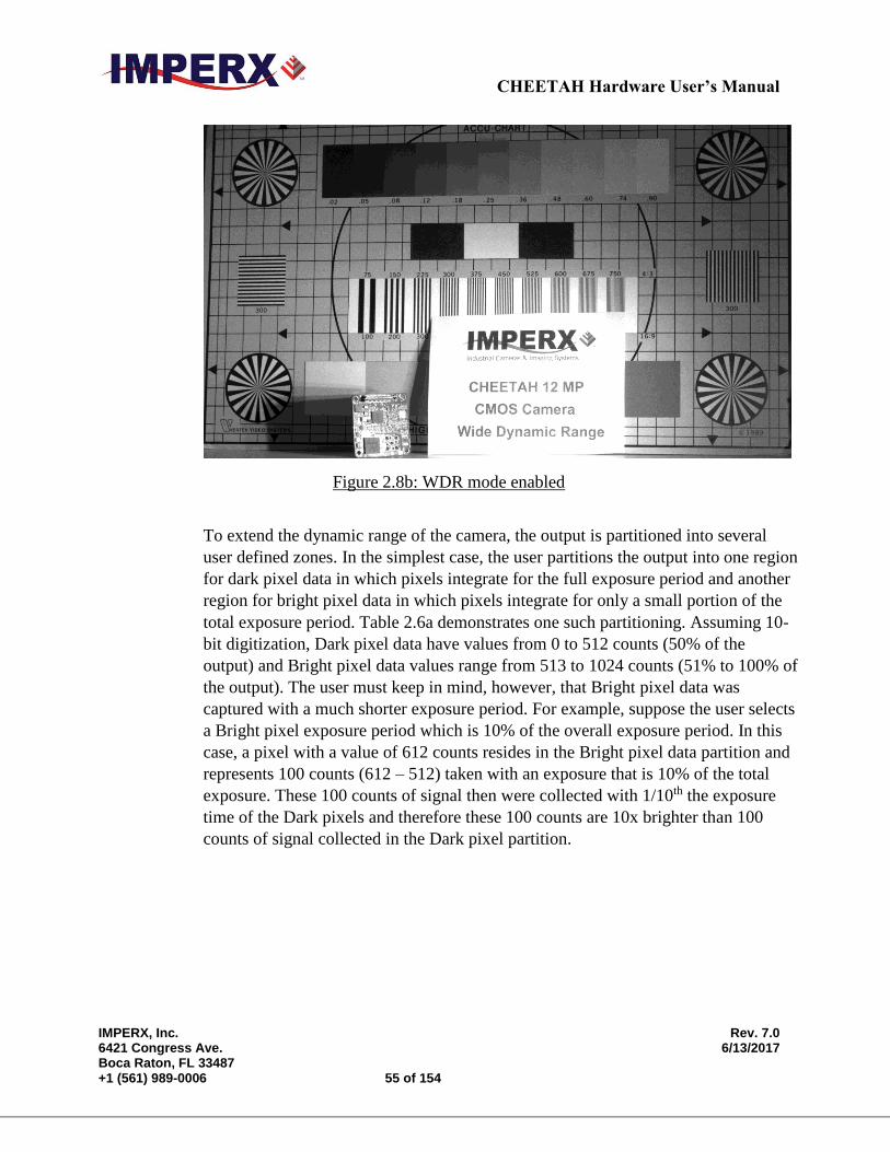
CHEETAH Hardware User’s Manual
IMPERX, Inc. Rev. 7.0 6421 Congress Ave. 6/13/2017 Boca Raton, FL 33487 +1 (561) 989-0006 55 of 154
Figure 2.8b: WDR mode enabled
To extend the dynamic range of the camera, the output is partitioned into several
user defined zones. In the simplest case, the user partitions the output into one region
for dark pixel data in which pixels integrate for the full exposure period and another
region for bright pixel data in which pixels integrate for only a small portion of the
total exposure period. Table 2.6a demonstrates one such partitioning. Assuming 10-
bit digitization, Dark pixel data have values from 0 to 512 counts (50% of the
output) and Bright pixel data values range from 513 to 1024 counts (51% to 100% of
the output). The user must keep in mind, however, that Bright pixel data was
captured with a much shorter exposure period. For example, suppose the user selects
a Bright pixel exposure period which is 10% of the overall exposure period. In this
case, a pixel with a value of 612 counts resides in the Bright pixel data partition and
represents 100 counts (612 – 512) taken with an exposure that is 10% of the total
exposure. These 100 counts of signal then were collected with 1/10th the exposure
time of the Dark pixels and therefore these 100 counts are 10x brighter than 100
counts of signal collected in the Dark pixel partition.

CHEETAH Hardware User’s Manual
IMPERX, Inc. Rev. 7.0 6421 Congress Ave. 6/13/2017 Boca Raton, FL 33487 +1 (561) 989-0006 56 of 154
Percentage of Output Pixel Data
100%
Bright Pixel Data
51%
50%
Dark Pixel Data
0%
Table 2.6a: Example of possible output partitioning for 2 intensity slopes
Table 2.6b is just one example of how the output can be partitioned into four
separate exposure zones. To reinforce the concept of output partitioning, let’s
suppose that the user selects the partitioning in Table 2.6b with 10-bit digitization
and selects the total exposure to be 50ms (Dark pixels), the Bright pixel exposure to
be 5ms, the Very Bright pixel exposure to be 0.5ms and the Ultra-Bright pixel
exposure to be 0.05ms. In this example (See Table 2.6b), Dark pixels with a 50ms
exposure are contained between 0 to 300 output counts (30% of output), Bright pixel
data with a 5ms exposure have counts between 301 to 600, Very Bright pixel data
with 0.5ms exposures have counts between 601 to 800 and Ultra-Bright pixel data
with 0.05ms exposures have counts between 800 to 1000. A single count in the
Ultra-Bright pixel data region represents signal that is 1,000x higher intensity (50ms
/ 0.05ms) than a single count in the Dark pixel data region.
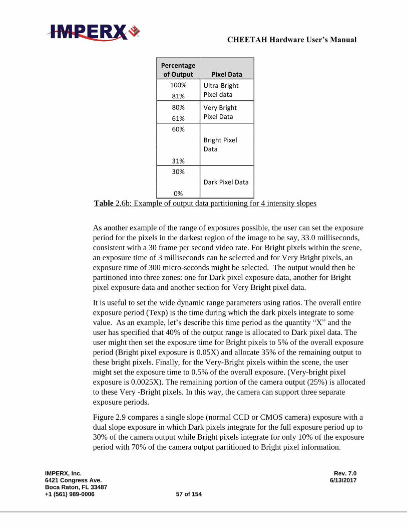
CHEETAH Hardware User’s Manual
IMPERX, Inc. Rev. 7.0 6421 Congress Ave. 6/13/2017 Boca Raton, FL 33487 +1 (561) 989-0006 57 of 154
Percentage of Output Pixel Data
100% Ultra-Bright Pixel data 81%
80% Very Bright Pixel Data 61%
60%
Bright Pixel Data
31%
30%
Dark Pixel Data
0%
Table 2.6b: Example of output data partitioning for 4 intensity slopes
As another example of the range of exposures possible, the user can set the exposure
period for the pixels in the darkest region of the image to be say, 33.0 milliseconds,
consistent with a 30 frame per second video rate. For Bright pixels within the scene,
an exposure time of 3 milliseconds can be selected and for Very Bright pixels, an
exposure time of 300 micro-seconds might be selected. The output would then be
partitioned into three zones: one for Dark pixel exposure data, another for Bright
pixel exposure data and another section for Very Bright pixel data.
It is useful to set the wide dynamic range parameters using ratios. The overall entire
exposure period (Texp) is the time during which the dark pixels integrate to some
value. As an example, let’s describe this time period as the quantity “X” and the
user has specified that 40% of the output range is allocated to Dark pixel data. The
user might then set the exposure time for Bright pixels to 5% of the overall exposure
period (Bright pixel exposure is 0.05X) and allocate 35% of the remaining output to
these bright pixels. Finally, for the Very-Bright pixels within the scene, the user
might set the exposure time to 0.5% of the overall exposure. (Very-bright pixel
exposure is 0.0025X). The remaining portion of the camera output (25%) is allocated
to these Very -Bright pixels. In this way, the camera can support three separate
exposure periods.
Figure 2.9 compares a single slope (normal CCD or CMOS camera) exposure with a
dual slope exposure in which Dark pixels integrate for the full exposure period up to
30% of the camera output while Bright pixels integrate for only 10% of the exposure
period with 70% of the camera output partitioned to Bright pixel information.

CHEETAH Hardware User’s Manual
IMPERX, Inc. Rev. 7.0 6421 Congress Ave. 6/13/2017 Boca Raton, FL 33487 +1 (561) 989-0006 58 of 154
0
0.2
0.4
0.6
0.8
1
0.1 0.2 0.3 0.4 0.5 0.6 0.7 0.8 0.9 1
Dual Slope Vs. Single Slope IntegrationsBright pixels integrate for 10% of exposure using 70% of
the output
Dark Pixels slope (WDR Mode) Bright Pixels slope (WDR mod)
Non-WDR mode slope
Figure 2.9: Dual Slope vs Single Slope Integration
The user can translate pixel data back to linear space by accounting for the different
exposure periods in each of the output partitions. For example, suppose Bright pixel
data is contained between 301 and 1000 of the camera output counts (10 bit system).
By subtracting, 300 from every pixel with a value greater than 300 counts and
multiplying the result by the ratio of the Total Exposure (Texp) period divided by the
Bright pixel exposure period, the Bright pixel data can be properly referenced to the
Dark pixel data.
Bright pixel (Linear) = (Bright pixel counts– Dark pixel max counts) x (Texp /
Bright pixel exposure period)
Another way to view the data partitioning concept is to use view the histogram of the
output data. In Figure 2.10, a histogram is shown with four output partitions. Again,
the user must bear in mind that each data region (Dark, Bright, Very Bright and
Ultra-Bright) has a different exposure time.
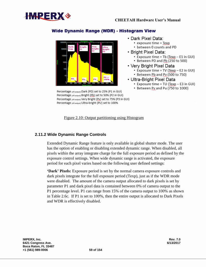
CHEETAH Hardware User’s Manual
IMPERX, Inc. Rev. 7.0 6421 Congress Ave. 6/13/2017 Boca Raton, FL 33487 +1 (561) 989-0006 59 of 154
Figure 2.10: Output partitioning using Histogram
2.11.2 Wide Dynamic Range Controls
Extended Dynamic Range feature is only available in global shutter mode. The user
has the option of enabling or disabling extended dynamic range. When disabled, all
pixels within the array integrate charge for the full exposure period as defined by the
exposure control settings. When wide dynamic range is activated, the exposure
period for each pixel varies based on the following user defined settings:
‘Dark’ Pixels: Exposure period is set by the normal camera exposure controls and
dark pixels integrate for the full exposure period (Texp), just as if the WDR mode
were disabled. The amount of the camera output allocated to dark pixels is set by
parameter P1 and dark pixel data is contained between 0% of camera output to the
P1 percentage level. P1 can range from 15% of the camera output to 100% as shown
in Table 2.6c. If P1 is set to 100%, then the entire output is allocated to Dark Pixels
and WDR is effectively disabled.
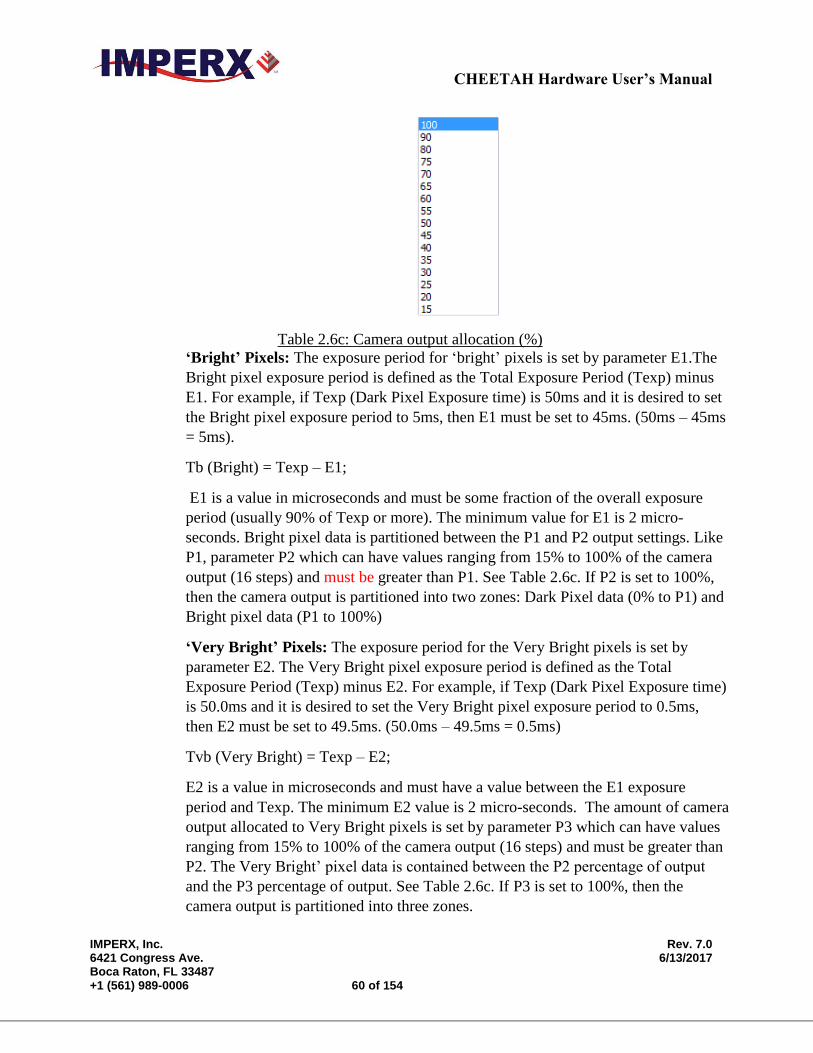
CHEETAH Hardware User’s Manual
IMPERX, Inc. Rev. 7.0 6421 Congress Ave. 6/13/2017 Boca Raton, FL 33487 +1 (561) 989-0006 60 of 154
Table 2.6c: Camera output allocation (%)
‘Bright’ Pixels: The exposure period for ‘bright’ pixels is set by parameter E1.The
Bright pixel exposure period is defined as the Total Exposure Period (Texp) minus
E1. For example, if Texp (Dark Pixel Exposure time) is 50ms and it is desired to set
the Bright pixel exposure period to 5ms, then E1 must be set to 45ms. (50ms – 45ms
= 5ms).
Tb (Bright) = Texp – E1;
E1 is a value in microseconds and must be some fraction of the overall exposure
period (usually 90% of Texp or more). The minimum value for E1 is 2 micro-
seconds. Bright pixel data is partitioned between the P1 and P2 output settings. Like
P1, parameter P2 which can have values ranging from 15% to 100% of the camera
output (16 steps) and must be greater than P1. See Table 2.6c. If P2 is set to 100%,
then the camera output is partitioned into two zones: Dark Pixel data (0% to P1) and
Bright pixel data (P1 to 100%)
‘Very Bright’ Pixels: The exposure period for the Very Bright pixels is set by
parameter E2. The Very Bright pixel exposure period is defined as the Total
Exposure Period (Texp) minus E2. For example, if Texp (Dark Pixel Exposure time)
is 50.0ms and it is desired to set the Very Bright pixel exposure period to 0.5ms,
then E2 must be set to 49.5ms. (50.0ms – 49.5ms = 0.5ms)
Tvb (Very Bright) = Texp – E2;
E2 is a value in microseconds and must have a value between the E1 exposure
period and Texp. The minimum E2 value is 2 micro-seconds. The amount of camera
output allocated to Very Bright pixels is set by parameter P3 which can have values
ranging from 15% to 100% of the camera output (16 steps) and must be greater than
P2. The Very Bright’ pixel data is contained between the P2 percentage of output
and the P3 percentage of output. See Table 2.6c. If P3 is set to 100%, then the
camera output is partitioned into three zones.
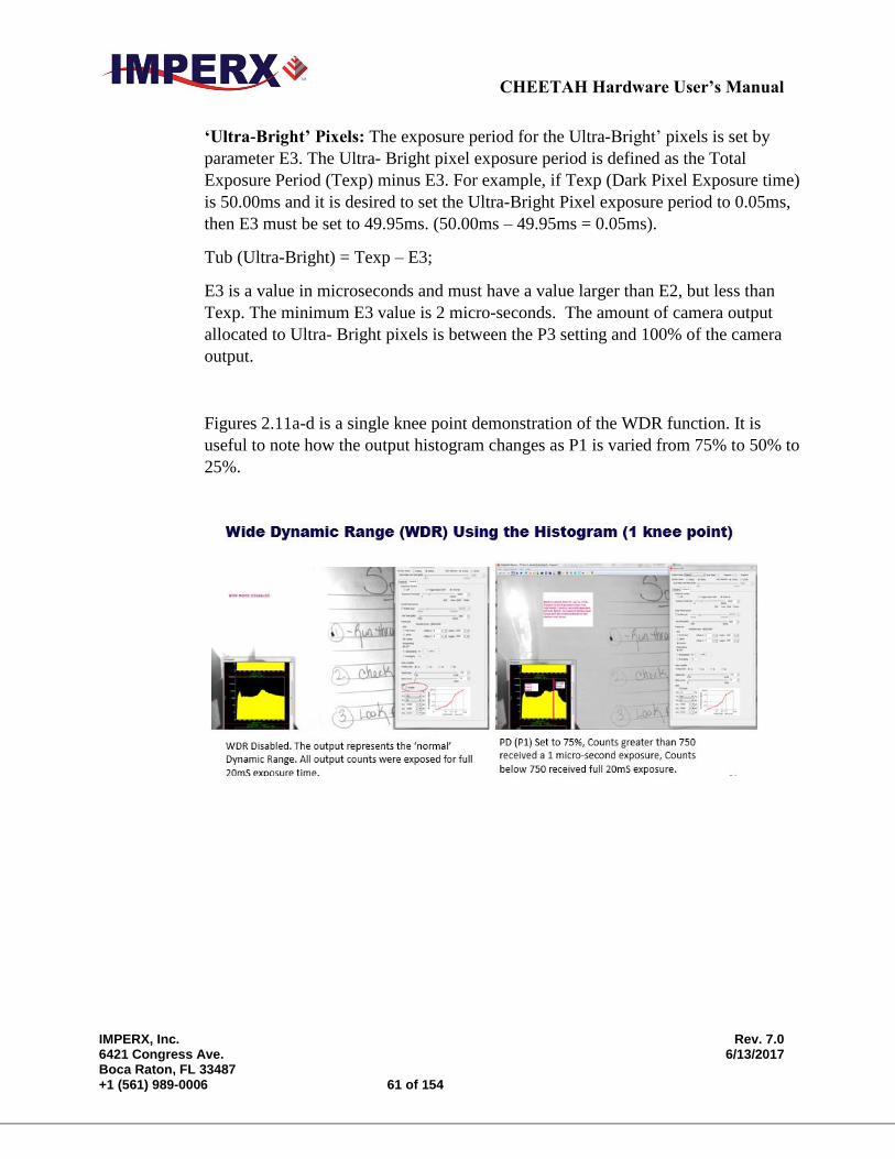
CHEETAH Hardware User’s Manual
IMPERX, Inc. Rev. 7.0 6421 Congress Ave. 6/13/2017 Boca Raton, FL 33487 +1 (561) 989-0006 61 of 154
‘Ultra-Bright’ Pixels: The exposure period for the Ultra-Bright’ pixels is set by
parameter E3. The Ultra- Bright pixel exposure period is defined as the Total
Exposure Period (Texp) minus E3. For example, if Texp (Dark Pixel Exposure time)
is 50.00ms and it is desired to set the Ultra-Bright Pixel exposure period to 0.05ms,
then E3 must be set to 49.95ms. (50.00ms – 49.95ms = 0.05ms).
Tub (Ultra-Bright) = Texp – E3;
E3 is a value in microseconds and must have a value larger than E2, but less than
Texp. The minimum E3 value is 2 micro-seconds. The amount of camera output
allocated to Ultra- Bright pixels is between the P3 setting and 100% of the camera
output.
Figures 2.11a-d is a single knee point demonstration of the WDR function. It is
useful to note how the output histogram changes as P1 is varied from 75% to 50% to
25%.
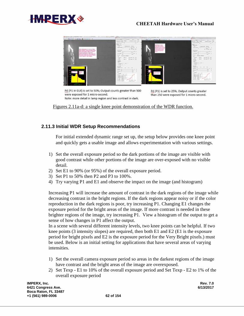
CHEETAH Hardware User’s Manual
IMPERX, Inc. Rev. 7.0 6421 Congress Ave. 6/13/2017 Boca Raton, FL 33487 +1 (561) 989-0006 62 of 154
Figures 2.11a-d: a single knee point demonstration of the WDR function.
2.11.3 Initial WDR Setup Recommendations
For initial extended dynamic range set up, the setup below provides one knee point
and quickly gets a usable image and allows experimentation with various settings.
1) Set the overall exposure period so the dark portions of the image are visible with
good contrast while other portions of the image are over-exposed with no visible
detail.
2) Set E1 to 90% (or 95%) of the overall exposure period.
3) Set P1 to 50% then P2 and P3 to 100%.
4) Try varying P1 and E1 and observe the impact on the image (and histogram)
Increasing P1 will increase the amount of contrast in the dark regions of the image while
decreasing contrast in the bright regions. If the dark regions appear noisy or if the color
reproduction in the dark regions is poor, try increasing P1. Changing E1 changes the
exposure period for the bright areas of the image. If more contrast is needed in these
brighter regions of the image, try increasing P1. View a histogram of the output to get a
sense of how changes in P1 affect the output.
In a scene with several different intensity levels, two knee points can be helpful. If two
knee points (3 intensity slopes) are required, then both E1 and E2 (E1 is the exposure
period for bright pixels and E2 is the exposure period for the Very Bright pixels.) must
be used. Below is an initial setting for applications that have several areas of varying
intensities.
1) Set the overall camera exposure period so areas in the darkest regions of the image
have contrast and the bright areas of the image are overexposed.
2) Set Texp - E1 to 10% of the overall exposure period and Set Texp - E2 to 1% of the
overall exposure period
CHEETAH Hardware User’s Manual
IMPERX, Inc. Rev. 7.0 6421 Congress Ave. 6/13/2017 Boca Raton, FL 33487 +1 (561) 989-0006 63 of 154
3) Set P1 to 40%, P2 to 70% and P3 to 100%.
Extended dynamic range images will look ‘flat’ and ‘dark’, because the bright areas of
the image have been compressed into the camera’s output range. Viewing the histogram
of the output is a very useful tool for seeing the impact of changes to P1, P2 and P3
settings. The LUT function can be used to stretch the image and increase the image
‘brightness’, if needed, keeping in mind that data is not linear and is partitioned into
different exposure ranges.
2.11.4 WDR at maximum frame rates (image artifact prevention)
To provide the highest frame rates, the exposure time and readout time overlap- meaning
while Frame 1 is being readout out, Frame 2 is being exposed. The exposure period for
Frame 2 is always positioned at the end of the Frame 1 and any additional WDR exposures
(E1, E2 and E3) are positioned at the very end of the overall exposure time.
When the application demands maximum frame rate, then the exposure period of Frame 2
overlaps with the readout of Frame 1. (For lower frame rate applications, the exposure for
Frame 2 will occur after Frame 1 is readout (non-overlapping)). An image artifact (a faint
horizontal line) may be seen at the beginning of the WDR (E1, E2 and E3) exposures, if the
WDR exposures for Frame 2 overlap with the Frame 1 readout time. At maximum frame
rate, these artifacts typically occur very near the bottom of the image.
For example, suppose the camera is providing a system constrained maximum frame rate of
50 fps (20,000 micro-second frame time). Let’s also suppose that the exposure time (Texp)
is set to 5,000 micro-seconds and two additional WDR exposures (E1 and E2) are used. E1
is set to 4,000 micro-seconds (a WDR exposure of 1,000 micro-seconds) and E2 is set to
4,900 micro-seconds (a 2nd WDR exposure of 100 micro-seconds). Let’s also assume a full
4000 x 3000 resolution image is readout from the C4080 camera and Frame 1 begins
reading out at time equals 0 seconds. In this example, the exposure for Frame 2 begins 15,
000 micro-seconds after the Frame 1 readout begins (5,000 microseconds before the end of
the Frame 1 readout time) and the first WDR exposure (E1) begins 1,000 micro-seconds
before the end of Frame 1 readout. Finally, the 2nd WDR exposure (E2) begins 100 micro-
seconds before the end of the Frame 1 readout. In this example, two line artifacts may be
seen. These artifacts will be located where they occurred with respect to the readout of
Frame 1 in time. For the E1 exposure, the artifact may be seen at image line 150 (1000
micro-seconds before the end of the frame readout) and, for the E2 exposure, an artifact at
line 15 (100 micro-seconds before the end of the Frame 1 readout) maybe observed. If the
E1 and E2 exposures do not overlap with the readout of Frame 1, no artifacts will be
observed.
To eliminate these artifacts when trying to achieve maximum frame rates:
CHEETAH Hardware User’s Manual
IMPERX, Inc. Rev. 7.0 6421 Congress Ave. 6/13/2017 Boca Raton, FL 33487 +1 (561) 989-0006 64 of 154
Enable the Fixed Frame Period control to increase the frame time slightly so
the WDR exposures occur after the frame readout ends. For example, if the
minimum frame time is 20ms (50 fps) and the longest WDR exposure desired is
2ms (so the WDR exposure occurs 2ms before the end of the frame time), then
use the Fixed Frame Period control to increase the frame time by 2ms to 22ms.
Use trigger mode, WDR image artifacts will never be present, because the
exposure and readout are not overlapped in triggered mode.
2.12 DATA OUTPUT FORMAT
2.12.1 Bit Depth
The internal digitization level within the image sensor can be varied to improve
frame rate. 10-bit digitization level allows the on-chip A/D converters to settle more
quickly enabling higher frame rates while 12-bit digitization levels provides higher
dynamic range at the expense of frame rate. The camera can output the data in 12, 10
or 8 bit format. In 8-bit output, standard bit reduction process is used and the least
significant bits are truncated
- “12-bit” digitization (See Figure 2.12)
If the camera is set to output 12-bit data, the image sensor data bits are
mapped to D0 (LSB) to D11 (MSB) output bits.
If the camera is set to output 10-bit data, the image sensor most-
significant data bits [D2 to D11] are mapped to the D0 (LSB) to D9
(MSB) output bits.
If the camera is set to output 8-bit data, the image sensor most significant
data bits [D4 to D11] are mapped to D0 (LSB) to D7 (MSB)
- “10-bit” digitization (See Figure 2.13)
If the camera is set to output 12-bit data, the image sensor data bits are
mapped to the D2 (LSB) to D11 (MSB) output bits and output bits D0
and D1 are set to zero.
If the camera is set to output 10-bit data, the image sensor data bits are
mapped directly to D0 (LSB) to D9 (MSB)
If the camera is set to output 8-bit data, the image sensor data most
significant data bits (D2 to D9) are mapped to D0 (LSB) to D7 (MSB).
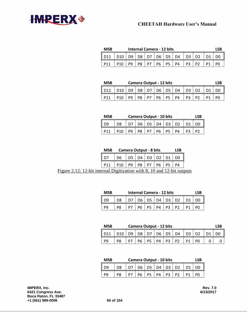
CHEETAH Hardware User’s Manual
IMPERX, Inc. Rev. 7.0 6421 Congress Ave. 6/13/2017 Boca Raton, FL 33487 +1 (561) 989-0006 65 of 154
MSB Internal Camera - 12 bits
LSB
D11 D10 D9 D8 D7 D6 D5 D4 D3 D2 D1 D0
P11 P10 P9 P8 P7 P6 P5 P4 P3 P2 P1 P0
MSB Camera Output - 12 bits
LSB
D11 D10 D9 D8 D7 D6 D5 D4 D3 D2 D1 D0
P11 P10 P9 P8 P7 P6 P5 P4 P3 P2 P1 P0
MSB Camera Output - 10 bits
LSB
D9 D8 D7 D6 D5 D4 D3 D2 D1 D0
P11 P10 P9 P8 P7 P6 P5 P4 P3 P2
MSB Camera Output - 8 bits LSB
D7 D6 D5 D4 D3 D2 D1 D0
P11 P10 P9 P8 P7 P6 P5 P4 Figure 2.12: 12-bit internal Digitization with 8, 10 and 12-bit outputs
MSB Internal Camera - 12 bits
LSB
D9 D8 D7 D6 D5 D4 D3 D2 D1 D0
P9 P8 P7 P6 P5 P4 P3 P2 P1 P0
MSB Camera Output - 12 bits
LSB
D11 D10 D9 D8 D7 D6 D5 D4 D3 D2 D1 D0
P9 P8 P7 P6 P5 P4 P3 P2 P1 P0 0 0
MSB Camera Output - 10 bits
LSB
D9 D8 D7 D6 D5 D4 D3 D2 D1 D0
P9 P8 P7 P6 P5 P4 P3 P2 P1 P0
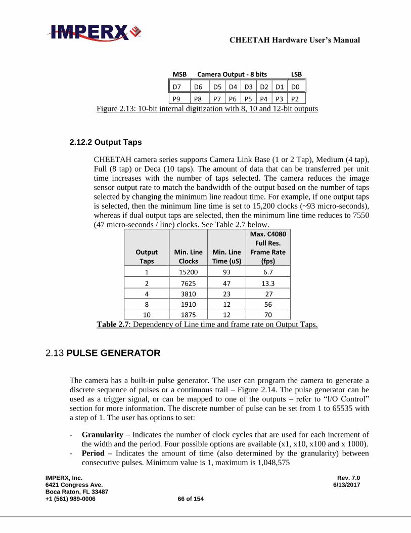
CHEETAH Hardware User’s Manual
IMPERX, Inc. Rev. 7.0 6421 Congress Ave. 6/13/2017 Boca Raton, FL 33487 +1 (561) 989-0006 66 of 154
MSB Camera Output - 8 bits LSB
D7 D6 D5 D4 D3 D2 D1 D0
P9 P8 P7 P6 P5 P4 P3 P2 Figure 2.13: 10-bit internal digitization with 8, 10 and 12-bit outputs
2.12.2 Output Taps
CHEETAH camera series supports Camera Link Base (1 or 2 Tap), Medium (4 tap),
Full (8 tap) or Deca (10 taps). The amount of data that can be transferred per unit
time increases with the number of taps selected. The camera reduces the image
sensor output rate to match the bandwidth of the output based on the number of taps
selected by changing the minimum line readout time. For example, if one output taps
is selected, then the minimum line time is set to 15,200 clocks (~93 micro-seconds),
whereas if dual output taps are selected, then the minimum line time reduces to 7550
(47 micro-seconds / line) clocks. See Table 2.7 below.
Output Taps
Min. Line Clocks
Min. Line Time (uS)
Max. C4080 Full Res.
Frame Rate (fps)
1 15200 93 6.7
2 7625 47 13.3
4 3810 23 27
8 1910 12 56
10 1875 12 70
Table 2.7: Dependency of Line time and frame rate on Output Taps.
2.13 PULSE GENERATOR
The camera has a built-in pulse generator. The user can program the camera to generate a
discrete sequence of pulses or a continuous trail – Figure 2.14. The pulse generator can be
used as a trigger signal, or can be mapped to one of the outputs – refer to “I/O Control”
section for more information. The discrete number of pulse can be set from 1 to 65535 with
a step of 1. The user has options to set:
- Granularity – Indicates the number of clock cycles that are used for each increment of
the width and the period. Four possible options are available (x1, x10, x100 and x 1000).
- Period – Indicates the amount of time (also determined by the granularity) between
consecutive pulses. Minimum value is 1, maximum is 1,048,575
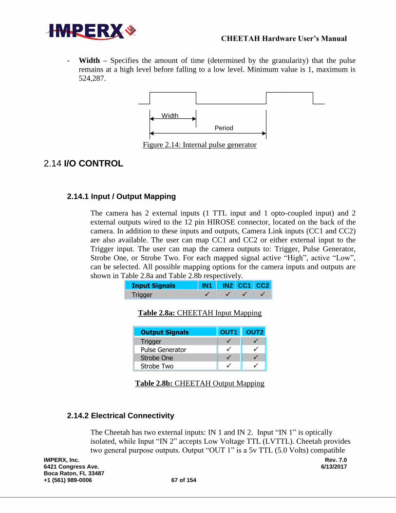
CHEETAH Hardware User’s Manual
IMPERX, Inc. Rev. 7.0 6421 Congress Ave. 6/13/2017 Boca Raton, FL 33487 +1 (561) 989-0006 67 of 154
- Width – Specifies the amount of time (determined by the granularity) that the pulse
remains at a high level before falling to a low level. Minimum value is 1, maximum is
524,287.
Period
Width
Figure 2.14: Internal pulse generator
2.14 I/O CONTROL
2.14.1 Input / Output Mapping
The camera has 2 external inputs (1 TTL input and 1 opto-coupled input) and 2
external outputs wired to the 12 pin HIROSE connector, located on the back of the
camera. In addition to these inputs and outputs, Camera Link inputs (CC1 and CC2)
are also available. The user can map CC1 and CC2 or either external input to the
Trigger input. The user can map the camera outputs to: Trigger, Pulse Generator,
Strobe One, or Strobe Two. For each mapped signal active “High”, active “Low”,
can be selected. All possible mapping options for the camera inputs and outputs are
shown in Table 2.8a and Table 2.8b respectively.
Input Signals IN1 IN2 CC1 CC2
Trigger
Table 2.8a: CHEETAH Input Mapping
Output Signals OUT1 OUT2
Trigger
Pulse Generator
Strobe One
Strobe Two
Table 2.8b: CHEETAH Output Mapping
2.14.2 Electrical Connectivity
The Cheetah has two external inputs: IN 1 and IN 2. Input “IN 1” is optically
isolated, while Input “IN 2” accepts Low Voltage TTL (LVTTL). Cheetah provides
two general purpose outputs. Output “OUT 1” is a 5v TTL (5.0 Volts) compatible
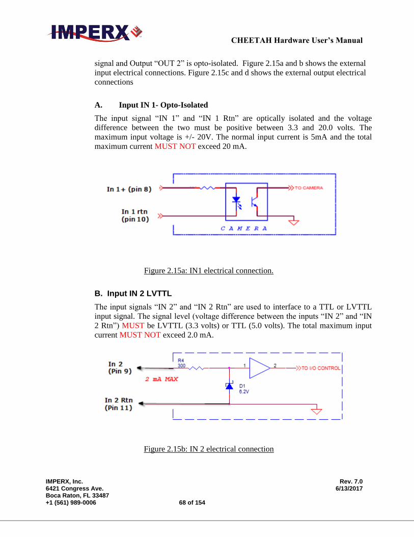
CHEETAH Hardware User’s Manual
IMPERX, Inc. Rev. 7.0 6421 Congress Ave. 6/13/2017 Boca Raton, FL 33487 +1 (561) 989-0006 68 of 154
signal and Output “OUT 2” is opto-isolated. Figure 2.15a and b shows the external
input electrical connections. Figure 2.15c and d shows the external output electrical
connections
A. Input IN 1- Opto-Isolated
The input signal “IN 1” and “IN 1 Rtn” are optically isolated and the voltage
difference between the two must be positive between 3.3 and 20.0 volts. The
maximum input voltage is +/- 20V. The normal input current is 5mA and the total
maximum current MUST NOT exceed 20 mA.
Figure 2.15a: IN1 electrical connection.
B. Input IN 2 LVTTL
The input signals “IN 2” and “IN 2 Rtn” are used to interface to a TTL or LVTTL
input signal. The signal level (voltage difference between the inputs “IN 2” and “IN
2 Rtn”) MUST be LVTTL (3.3 volts) or TTL (5.0 volts). The total maximum input
current MUST NOT exceed 2.0 mA.
Figure 2.15b: IN 2 electrical connection
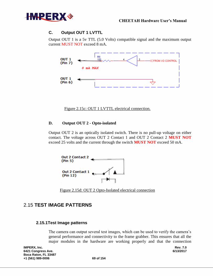
CHEETAH Hardware User’s Manual
IMPERX, Inc. Rev. 7.0 6421 Congress Ave. 6/13/2017 Boca Raton, FL 33487 +1 (561) 989-0006 69 of 154
C. Output OUT 1 LVTTL
Output OUT 1 is a 5v TTL (5.0 Volts) compatible signal and the maximum output
current MUST NOT exceed 8 mA.
Figure 2.15c: OUT 1 LVTTL electrical connection.
D. Output OUT 2 - Opto-isolated
Output OUT 2 is an optically isolated switch. There is no pull-up voltage on either
contact. The voltage across OUT 2 Contact 1 and OUT 2 Contact 2 MUST NOT
exceed 25 volts and the current through the switch MUST NOT exceed 50 mA.
Figure 2.15d: OUT 2 Opto-Isolated electrical connection
2.15 TEST IMAGE PATTERNS
2.15.1Test Image patterns
The camera can output several test images, which can be used to verify the camera’s
general performance and connectivity to the frame grabber. This ensures that all the
major modules in the hardware are working properly and that the connection
CHEETAH Hardware User’s Manual
IMPERX, Inc. Rev. 7.0 6421 Congress Ave. 6/13/2017 Boca Raton, FL 33487 +1 (561) 989-0006 70 of 154
between the frame grabber and the camera is synchronized – i.e., the image framing,
output mode, communication rate, etc. are properly configured. Please note that the
test image patterns do not exercise and verify the image sensor functionality.
The following test images are available:
- H Ramp Still – displays a stationary horizontal ramp image
- V Ramp Still – displays a stationary vertical ramp image
- H Ramp Move – displays a moving horizontal ramp image
- V Ramp Move – displays a moving vertical ramp image
- Cross-hairs – displays a cross-hair in the absolute center of the image (2000 x
1500). A live image is superimposed under the cross-hair pattern. (Cross-hair has
a thickness of 2 pixels)
2.16 WHITE BALANCE AND COLOR CONVERSION
2.16.1 White Balance Correction
The color representation in the image depends on the color temperature of the light
source and CHEETAH has a built-in algorithm to compensate for this effect. When
white balance correction is enabled, the camera collects the luminance data for each
of the primary colors R, G and B, analyzes it, and adjusts the color setting in order to
preserve the original colors and make white objects appear white. The algorithm
collects data from the entire image, and can work in four different modes – “Off”,
“Once”, “AWB Tracking” and “Manual”. When set to “Off”, no color correction is
performed. When set to “Once” the camera analyzes one image frame, calculates
only one set correction coefficients, and all subsequent frames are corrected with this
set of coefficients. When set to “Manual” the camera uses the correction coefficients
as entered from the user. In “Tracking” mode the camera analyzes every frame, a set
of correction coefficients are derived for each frame and applied to the next frame.
When “Auto-White Balance (AWB) Tracking” mode is selected, the user can select
5 tracking speeds from slow to fastest.
2.17 TRANSFER FUNCTION CORRECTION – USER LUT
The user defined LUT (Lookup Table) feature allows the user to modify and transform the
original video data into any arbitrary value – Figure 2.16. Any 12-bit value can be
transformed into any other 12-bit value. The camera supports two separate lookup tables,
each consisting of 4096 entries, with each entry being 12 bits wide. The first LUT is factory
programmed with a standard Gamma 0.45. The second LUT is not pre-programmed in the

CHEETAH Hardware User’s Manual
IMPERX, Inc. Rev. 7.0 6421 Congress Ave. 6/13/2017 Boca Raton, FL 33487 +1 (561) 989-0006 71 of 154
factory. Both LUT’s are available for modifications, and the user can generate and upload
his own custom LUT using the CHEETAH Configuration software – refer to Appendix B.
LUT12 bit input
data
12 bit output
data
Figure 2.16: Look up table
2.17.1 Standard Gamma Correction
The image generated by the camera is normally viewed on a CRT (or LCD) display,
does not have a linear transfer function – i.e., the display brightness is not linearly
proportional to the scene brightness (as captured by the camera). As the object
brightness is lowered, the brightness of the display correspondingly lowers. At a
certain brightness level, the scene brightness decrease does not lead to a
corresponding display brightness decrease. The same is valid if the brightness is
increased. This is because the display has a nonlinear transfer function and a
brightness dynamic range much lower than the camera. The camera has a built-in
transfer function to compensate for this non-linearity, which is called gamma
correction. If enabled, the video signal is transformed by a non-linear function close
to the square root function (0.45 power) – formula 2.4. In the digital domain this is a
nonlinear conversion from 12-bit to 12-bit – Figure 2.17.
Output signal [V] = (input signal [V]) 0.45 (2.4)
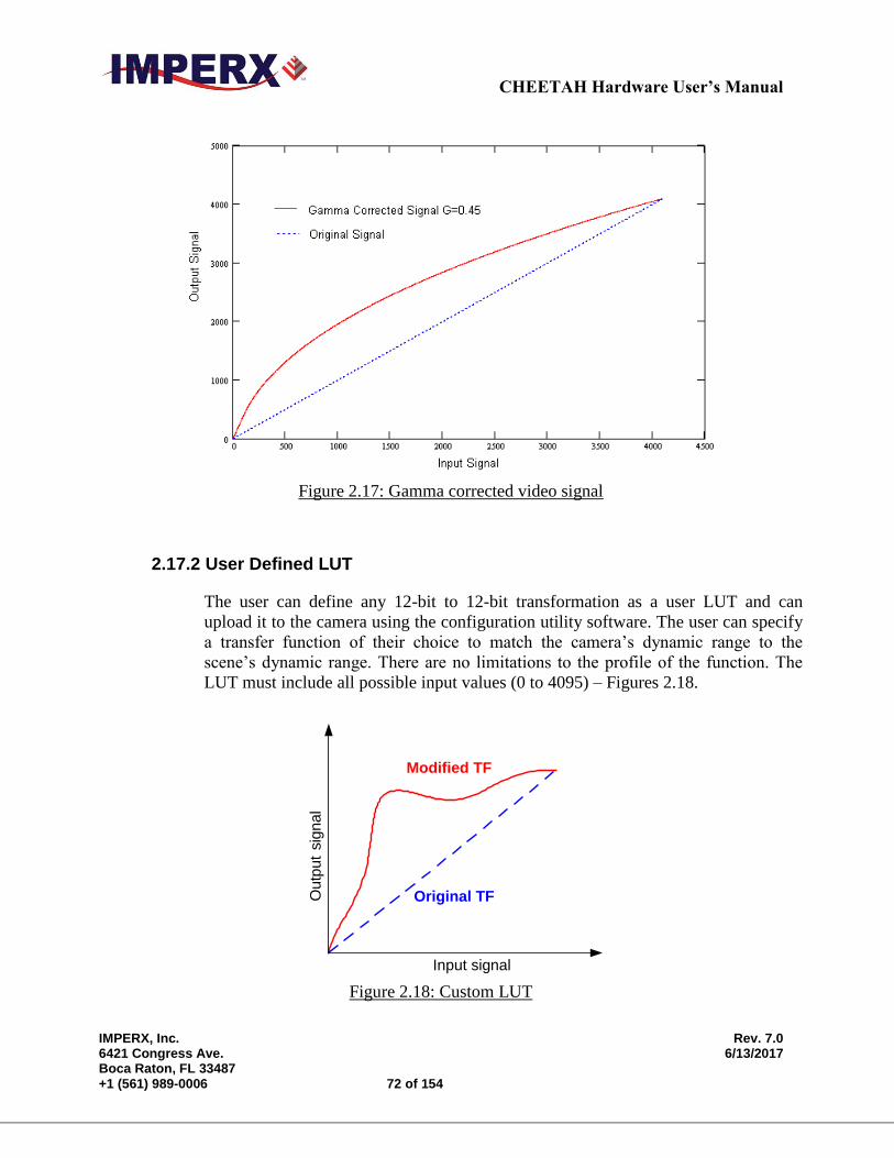
CHEETAH Hardware User’s Manual
IMPERX, Inc. Rev. 7.0 6421 Congress Ave. 6/13/2017 Boca Raton, FL 33487 +1 (561) 989-0006 72 of 154
Figure 2.17: Gamma corrected video signal
2.17.2 User Defined LUT
The user can define any 12-bit to 12-bit transformation as a user LUT and can
upload it to the camera using the configuration utility software. The user can specify
a transfer function of their choice to match the camera’s dynamic range to the
scene’s dynamic range. There are no limitations to the profile of the function. The
LUT must include all possible input values (0 to 4095) – Figures 2.18.
Input signal
Outp
ut
sig
nal
Original TF
Modified TF
Figure 2.18: Custom LUT
CHEETAH Hardware User’s Manual
Imperx, Inc. Rev. 7.0 6421 Congress Ave. 6/13/2017 Boca Raton, FL 33487 +1 (561) 989-0006 73 of 154
2.18 DEFECTIVE PIXEL CORRECTION
A CMOS imager is composed of a two-dimensional array of light sensitive pixels. In
general, the majority of the pixels have similar sensitivity. Unfortunately, there are some
pixels which sensitivity deviates from the average pixel sensitivity. A defective pixel is
defined as a pixel whose response deviates by more than 15% from the average response.
In extreme cases these pixels can be stuck ‘black’ or stuck ‘white’ and are non-responsive
to light. There are two major types of pixel defects – “Defective” and “Hot”.
1. ”Defective” – these are pixels which sensitivity deviates more than 15% due to
fluctuations in the CMOS manufacturing process. During final camera testing at the
factory up to 1024 defective pixels are identified and will be automatically corrected
if defective pixel correction is enabled. Two type of defective pixels are possible:
a. “DARK” is defined as a pixel, whose sensitivity is lower than the sensitivity of
the adjacent pixels. In some cases this pixel will have no response (completely
dark).
b. “BRIGHT” is defined as a pixel, whose sensitivity is higher than the sensitivity
of the adjacent pixels. In some cases this pixel will have full response (completely
bright).
2. “Hot” – these are pixels, which in normal camera operation behaves as normal pixel
(the sensitivity is equal to the one of the adjacent pixels), but during long time
integration behaves as a high intensity bright pixel. In some cases this pixel will have
full response (completely bright). During final camera testing at the factory, up to
8192 hot pixels will be identified and will be automatically corrected, if hot pixel
correction is enabled.
2.18.1 Static Pixel Correction
Static defective and Hot pixel correction works with predetermined and preloaded
Defective and Hot pixel maps. During factory final testing, our manufacturing
engineers run a program specially designed to identify these ‘defective’ and “hot”
pixels. The program creates a map file which lists the coordinates (i.e. row and
column) of every defective pixel. This file, called the Defect Pixel Map, is then
downloaded into the camera’s non-volatile memory. Users may wish, however, to
create and to upload their own DPM file because of the uniqueness of their
operating environment or camera use. When ‘Defective Pixel Correction’ is
enabled, the camera will compare each pixel’s coordinates with entries in the
‘defect’ map. If a match is found, then the camera will ‘correct’ the defective
pixel. When ‘Hot Pixel Correction’ is enabled, the camera will compare each
pixel’s coordinates with entries in the ‘defect’ map. If a match is found, then the
camera will ‘correct’ the hot pixel. The "Defective/Hot Pixel Map" can be
displayed upon user request.
CHEETAH Hardware User’s Manual
IMPERX, Inc. Rev. 7.0 6421 Congress Ave. 6/13/2017 Boca Raton, FL 33487 +1 (561) 989-0006 74 of 154
2.18.2 Dynamic Pixel Correction
Dynamic pixel correction works without preloaded pixel maps. When this option
is enabled, the camera determines which pixel needs correction and performs the
correction automatically. Static and Dynamic “Defective Pixel Correction” and
“Hot Pixel Correction” can be enabled independently or simultaneously. The
Dynamic Threshold can be set to have a value between 0 to 4096 (12-bit). This
threshold determines how much a pixel can deviate from neighboring pixels
(either brighter or darker) before a pixel is considered to be defective and
correction is applied to this pixel.
2.19 CAMERA INTERFACE
2.19.1 Status LED
The camera has a dual red-green LED, located on the back panel. The LED color
and light pattern indicate the camera status and mode of operation:
GREEN is steady ON – Normal operation. The user is expected to see a normal
image coming out of the camera.
GREEN blinks with frequency ~ 0.5 Hz – indicates trigger is enabled.
RED is steady ON – Test mode enabled.
LED is OFF – Power not present error. The camera has no power or indicates a
camera power supply failure. A faulty external AC adapter could also cause this.
To restore the camera operation, re-power the camera and load the factory
settings. If the LED is still “OFF”, please contact the factory for RMA.
2.19.2 Temperature Monitor
The camera has a built in temperature sensor which monitors the internal camera
temperature. The sensor is placed on the hottest spot in the camera. The internal
camera temperature is displayed on the Camera Configuration Utility screen and
can be queried by the user at any time – refer to Camera Configuration section.
2.19.3 Exposure Time Monitor
The camera has a built in exposure time monitor. In any mode of operation (i.e.
normal, AOI, etc.) the user can query the camera for the current exposure time by
CHEETAH Hardware User’s Manual
IMPERX, Inc. Rev. 7.0 6421 Congress Ave. 6/13/2017 Boca Raton, FL 33487 +1 (561) 989-0006 75 of 154
issuing a command – refer to the Exposure Control section. The current camera
integration time in units of microseconds will be returned.
2.19.4 Frame Time Monitor
The camera has a built in frame rate monitor. In any mode of operation (i.e.
normal, AOI, etc.) the user can query the camera for the current frame rate by
issuing a command – refer to the Exposure Control section. The current camera
speed in units of frames per second will be returned.
2.19.5 Current image size
The camera image size can change based on a camera feature selected. In any
mode of operation (i.e. normal, AOI, etc.) the user can query the camera for the
current image size by issuing a command – refer to the Image Size section. The
current camera image size in (pixels x lines) will be returned.
CHEETAH Hardware User’s Manual
IMPERX, Inc. Rev. 7.0 6421 Congress Ave. 6/13/2017 Boca Raton, FL 33487 +1 (561) 989-0006 76 of 154
Chapter 3 Camera Configuration
Camera Configuration
This chapter discusses how to communicate with the camera and configure
the camera’s operating parameters.

CHEETAH Hardware User’s Manual
IMPERX, Inc. Rev. 7.0 6421 Congress Ave. 6/13/2017 Boca Raton, FL 33487 +1 (561) 989-0006 77 of 154
3.1 OVERVIEW
The CHEETAH series of cameras are highly programmable and flexible. All of the
cameras resources (internal registers, video amplifiers and parameter FLASH) can be
controlled by the user. The user communicates with the camera using a simple, register-
based, command protocol via the Camera Link’s serial interface. The interface is bi-
directional with the user issuing ‘commands’ to the camera and the camera issuing
‘responses’ (either status or info) to the user. The entire camera registers and resources
can be configured and monitored by the user. The camera’s parameters can be
programmed using the CHEETAH Configurator graphical user interface.
3.2 CAMERA CONFIGURATION
3.2.1 Configuration Memory – parameter FLASH
The camera has a built-in configuration memory divided into 4 segments: ‘work-
space’, ‘factory-space’, ‘user-space #1’ and ‘user-space #2’. The ‘work-space’
segment contains the current camera settings while the camera is powered-up and
operational. All camera registers are located in this space. These registers can be
programmed and retrieved via commands issued by the user. The workspace is
RAM based and upon power down all camera registers are cleared. The ‘factory-
space’ segment is ROM based, write protected and contains the default camera
settings. This space is available for read operations only. The ‘user-space #1’ and
‘user-space #2’ are non-volatile, FLASH based and used to store two user defined
configurations. Upon power up, the camera firmware loads the work-space
registers from the factory-space, user-space #1 or user-space #2 as determined by
a ‘boot control’ register located in the configuration memory. The ‘boot control’
register can be programmed by the user (refer to Camera Configuration Section).
The user can, at any time, instruct the camera to loads its workspace with the
contents of the ‘factory-space’, ‘user-space #1’ or ‘user-space #2’. Similarly, the
user can instruct the camera to save the current workspace settings into either the
‘user-space #1’ or ‘user-space #2’.
The non-volatile parameter FLASH memory also contains Defective Pixel Map,
Hot Pixel Map, LUT 1 and LUT 2, which can be loaded to the camera internal
memory upon enabling the corresponding camera feature. The user can create its
own DPM, HPM, and LUT tables and upload them to the parameter FLASH
using the CHEETAH Configurator graphical user interface.

CHEETAH Hardware User’s Manual
IMPERX, Inc. Rev. 7.0 6421 Congress Ave. 6/13/2017 Boca Raton, FL 33487 +1 (561) 989-0006 78 of 154
3.2.2 Camera Serial Protocol
In order to access the camera registers and resources a sequence of bytes needs to
be transmitted to the camera via the Camera Link serial interface. This is an
RS232, asynchronous, full-duplex, serial protocol, with 1 start bit, 8 data bits, 1
stop bit, no hand shake, and no parity – Figure 4.1. The default baud rate is
configurable (9600, 19200, 38400, 57600 and 115200 – default).
Figure 3.1: Serial protocol format
Each camera control register can be updated independently. In terms of the serial
protocol, all registers are defined as 16-bit address (hex format), and 32-bit data
(hex format). Camera registers using less than 32-bits in width must be padded
with ‘0’s on writes, and unused bits are ignored on reads. Register data is always
“packed low” within 32-bit data words for registers defined less than 32-bits.
There is a latency delay for each command due to command execution and data
transmission over the serial port. This latency varies from command to command
because of resource location and command response length.
3.2.2.1 Write Operation
In order to write to any given camera register, a sequence of 7 bytes should be
sent to the camera. If there is no error the camera returns one byte
acknowledge for the write command <Ack> - Figure 4.2. If there is an error
the camera returns two bytes not-acknowledge for the write command – the
first byte is <Nac> <Err>, the second is the error code – Figure 4.3a,b:
Write to camera (7 Bytes): <Write_Cmd> <Address> <Data>
1st
byte: 0x57 (Write Command)
2nd
byte: <Register Address_High> MSB
3rd
byte: <Register Address_Low> LSB
4th
byte: <Register Data Byte 4> MSB
5th
byte: <Register Data Byte 3> …
6th
byte: <Register Data Byte 2> …
7th
byte: <Register Data Byte 1> LSB

CHEETAH Hardware User’s Manual
IMPERX, Inc. Rev. 7.0 6421 Congress Ave. 6/13/2017 Boca Raton, FL 33487 +1 (561) 989-0006 79 of 154
Write Acknowledge (1 Byte): <Ack>
1st
byte: 0x06 (Acknowledge)
57 04 10 11 22 33 44
06
Rx
Tx
Wr_Cmd Addr Data
Ack
Figure 3.2: Normal write cycle
Write Not-acknowledge (2 Bytes): <Nac> <Error Code>
1st
byte: 0x15 (Not-acknowledge)
2nd
byte: <XX> (Nac Error Code. See Error Code Description section)
47 04 10 11 22
15
Rx
Tx
Cmd
Nak
01
Invalid Cmd
These characters are dropped
33 44
* * * * All subsequent Rx characters are
dropped until the receipt of a valid
( 52 or 57 ) command
* * * *
Figure 3.3a: Invalid command error
Tx
57 04 10 11 22
15
Rx
Wr_Cmd Addr
Nak
02
Timeoutt=0 t=100 mS
33 44
These characters
are dropped
* * * *
* * * * All subsequent Rx characters are
dropped until the receipt of a valid
( 52 or 57 ) command
Figure 3.3b: Rx timeout error
Example: Write to register address 0x0410, data value = 0x11223344:
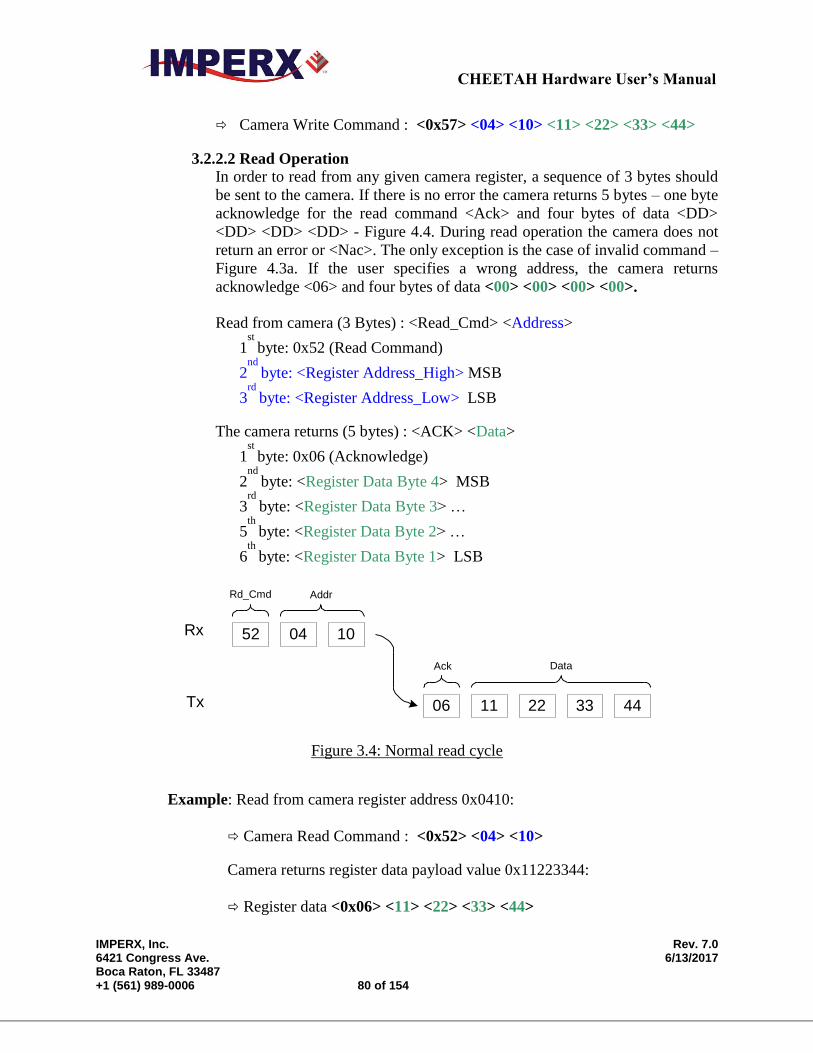
CHEETAH Hardware User’s Manual
IMPERX, Inc. Rev. 7.0 6421 Congress Ave. 6/13/2017 Boca Raton, FL 33487 +1 (561) 989-0006 80 of 154
Camera Write Command : <0x57> <04> <10> <11> <22> <33> <44>
3.2.2.2 Read Operation
In order to read from any given camera register, a sequence of 3 bytes should
be sent to the camera. If there is no error the camera returns 5 bytes – one byte
acknowledge for the read command <Ack> and four bytes of data <DD>
<DD> <DD> <DD> - Figure 4.4. During read operation the camera does not
return an error or <Nac>. The only exception is the case of invalid command –
Figure 4.3a. If the user specifies a wrong address, the camera returns
acknowledge <06> and four bytes of data <00> <00> <00> <00>.
Read from camera (3 Bytes) : <Read_Cmd> <Address>
1st
byte: 0x52 (Read Command)
2nd
byte: <Register Address_High> MSB
3rd
byte: <Register Address_Low> LSB
The camera returns (5 bytes) : <ACK> <Data>
1st
byte: 0x06 (Acknowledge)
2nd
byte: <Register Data Byte 4> MSB
3rd
byte: <Register Data Byte 3> …
5th
byte: <Register Data Byte 2> …
6th
byte: <Register Data Byte 1> LSB
52 04 10
11 22 33 4406
Rd_Cmd Addr
DataAck
Rx
Tx
Figure 3.4: Normal read cycle
Example: Read from camera register address 0x0410:
Camera Read Command : <0x52> <04> <10>
Camera returns register data payload value 0x11223344:
Register data <0x06> <11> <22> <33> <44>
CHEETAH Hardware User’s Manual
IMPERX, Inc. Rev. 7.0 6421 Congress Ave. 6/13/2017 Boca Raton, FL 33487 +1 (561) 989-0006 81 of 154
3.2.2.3 Error Code Description
To manage camera reliability, not-acknowledge error codes are defined as
follows:
x00 – No error
x01 – Invalid command. An invalid command (not 52 or 57) has been sent to
the camera.
x02 – Time-out.
x03 – Checksum error
x04 – Value less then minimum
x05 – Value higher than maximum
x06 – AGC error
x07 – Supervisor mode error
x08 – Mode not supported error
3.3 CAMERA CONFIGURATION REGISTER DESCRIPTION
3.3.1 Startup Procedure
Upon power on or receipt of a ‘SW_Reset’ command, the camera performs the
following steps:
1. Boot loader checks Program FLASH memory for a valid Firmware image and
loads it into the FPGA.
2. The camera reads the ‘Boot From’ register from the parameter FLASH and
loads its workspace from one of the configuration spaces as determined by the
‘Boot From’ data. The available configuration spaces are: ‘Factory…’, ‘User #1…’, ‘User #2…’
3. The camera is initialized and ready to accept user commands.
3.3.2 Saving and Restoring Settings
Operational settings for the camera may be stored for later retrieval in its non-
volatile memory. Three separate configuration spaces exist for storing these
settings: ‘factory’ space, ‘user #1’ space and ‘user #2’ space. The factory space is
pre-programmed by factory personnel during the manufacturing process. This
space is write protected and cannot be altered by the user. Two user spaces are
also provided allowing the user to store his/her own preferences. The camera can
be commanded to load its internal workspace, from either of the three
configuration spaces, at any time. The user can also define from which space the
CHEETAH Hardware User’s Manual
IMPERX, Inc. Rev. 7.0 6421 Congress Ave. 6/13/2017 Boca Raton, FL 33487 +1 (561) 989-0006 82 of 154
camera should automatically load itself following a power cycle or receipt of a
reset (‘SW_Reset’) command.
3.3.2.1 Boot From
This register determines which configuration space (factory, user#1 or user
#2) should be loaded into the camera following a power cycle or reset
(‘SW_Reset’) command. Upon a power cycle or reset, the camera reads the
‘boot from’ value from non-volatile memory and loads the appropriate
configuration space.
Address : 0x6000
Data (1- 0) : 00 – Boot from Factory
01 – Boot from User #1
: 10 – Boot from User #2
Data (31- 2) : N/A
3.3.2.2 Load From Factory
The ‘Load From Factory’ command instructs the camera to load its
workspace from the factory space. All current workspace settings will be
replaced with the contents of the factory space. This is a command, not a
register. The act of writing to this location initiates the load from the factory.
Address : 0x6060
3.3.2.3 Load From User #1
The ‘Load From User #1’ command instructs the camera to load its
workspace from the user #1 space. All current workspace settings will be
replaced with the contents of the user #1 space. This is a command, not a
register. The act of writing to this location initiates the load from the user #1.
Address : 0x6064
3.3.2.4 Load From User #2
The ‘Load From User #2’ command instructs the camera to load its
workspace from the user #2 space. All current workspace settings will be
replaced with the contents of the user #2 space. This is a command, not a
register. The act of writing to this location initiates the load from the user #2.
Address : 0x6068
CHEETAH Hardware User’s Manual
IMPERX, Inc. Rev. 7.0 6421 Congress Ave. 6/13/2017 Boca Raton, FL 33487 +1 (561) 989-0006 83 of 154
3.3.2.5 Save to User #1
The ‘Save To User #1’ command instructs the camera to save its
workspace to the user #1 space. All current workspace settings will be saved
to the user #1 space. This is a command, not a register. The act of writing to
this location initiates the save to user #1 space.
Address : 0x6074
3.3.2.6 Save to User #2
The ‘Save To User #2’ command instructs the camera to save its
workspace to the user #2 space. All current workspace settings will be saved
to the user #2 space. This is a command, not a register. The act of writing to
this location initiates the save to user #2 space.
Address : 0x6078
3.3.2.7 SW_Reset
The ‘SW_Reset’ command instructs the camera to initiate software reset,
which resets the camera and loads its workspace from one of the configuration
spaces as determined by the ‘Boot From’ data. Although, this is a command,
the user MUST write a specific data 0xDEADBEEF in order to initiate the
reset sequence.
Address : 0x601C
Data : 0xDEADBEEF
3.3.3 Retrieving Manufacturing Data
The camera contains non-volatile memory that stores manufacturing related
information. This information is programmed in the factory during the
manufacturing process.
3.3.3.1 Firmware Revision
This register returns the camera main firmware revision.
Address : 0x6004
Data (31:28) : <FW image>
Data (27:24) : <CMOS Type>
Data (23:0) : <FW revision>
CHEETAH Hardware User’s Manual
IMPERX, Inc. Rev. 7.0 6421 Congress Ave. 6/13/2017 Boca Raton, FL 33487 +1 (561) 989-0006 84 of 154
3.3.3.2 Firmware Build Number
This register returns the firmware build number, which tracks custom
firmware for specific applications.
Address : 0x6038
Data : <FPGA, EPCS ID, Customer ID>
3.3.3.3 Assembly Part Number
This register returns the camera assembly part number – the complete
assembly part number is 4 registers.
Address : 0x7004, 0x7008, 0x700C, 0x7010
Data : <Assembly Part Number>
3.3.3.4 Camera Serial Number
This register returns the camera serial number – the complete serial number is
2 registers.
Address : 0x7014, 0x7018
Data : <Camera Serial Number>
3.3.3.5 CMOS Serial Number
This register returns the CMOS imager number – the complete CMOS number
is 2 registers.
Address : 0x701C, 0x7020
Data : <CMOS Image Sensor Serial Number>
3.3.3.6 Date of Manufacture
This register returns the camera date of manufacture – The complete date of
manufacture is 2 registers.
Address : 0x7024, 0x7028
Data : <Date of Manufacture>
3.3.3.7 Camera Type
This register returns the camera type – The complete assembly is 4 registers.
Address : 0x7040,
Data : <Camera Type: 0x0 = Mono, 0xC= Color>
Sensor Type ( 0x7040 ) 0x0=Mono, 0xC=Color
CHEETAH Hardware User’s Manual
IMPERX, Inc. Rev. 7.0 6421 Congress Ave. 6/13/2017 Boca Raton, FL 33487 +1 (561) 989-0006 85 of 154
3.3.4 Camera Information Registers
The camera has a set of information registers, which provide information for the
camera current status, frame rate, exposure time, image size, etc.
3.3.4.1 Current Frame “A” Horizontal Frame Size
This register returns the current horizontal image frame size in pixels.
Address : 0x6090
Data (15:0) : <Current Horizontal Size>
Data (31:16) : <N/A>
3.3.4.2 Current Frame “A” Vertical Frame Size
This register returns the current vertical image frame size in lines.
Address : 0x6094
Data (15:0) : <Current Vertical Size>
Data (31:16) : <N/A>
3.3.4.3 Current Frame “B” Horizontal Frame Size
This register returns the current horizontal image frame size in pixels.
Address : 0x6098
Data (15:0) : <Current Horizontal Size>
Data (31:16) : <N/A>
3.3.4.4 Current Frame “B” Vertical Frame Size
This register returns the current vertical image frame size in lines.
Address : 0x609C
Data (15:0) : <Current Vertical Size>
Data (31:16) : <N/A>
3.3.4.5 Current Frame “A” Frame Time
This register returns the current frame time for Frame A in us.
Address : 0x6084
Data (23:0) : < Frame Time>
Data (31:24) : N/A
3.3.4.6 Current Frame “B” Frame Time
This register returns the current frame time for Frame B in us.
Address : 0x608C
Data (23:0) : < Frame Time>

CHEETAH Hardware User’s Manual
IMPERX, Inc. Rev. 7.0 6421 Congress Ave. 6/13/2017 Boca Raton, FL 33487 +1 (561) 989-0006 86 of 154
Data (31:24) : N/A
3.3.4.7 Current Minimum Frame “A” Line Time
This register returns the current minimum line time for Frame “A” in pixel
clocks (160 Mhz, 6.25nS)
Address : 0x60B0
Data (15:0) : <Minimum Line Time>
Data (31- 16) : N/A
3.3.4.8 Current Minimum Frame “B” Line Time
This register returns the current minimum line time for Frame “B” in pixel
clocks (160 MHz, 6.25nS)
Address : 0x60B4
Data (15:0) : <Minimum Line Time>
Data (31- 16) : N/A
3.3.4.9 Current Frame “A” Exposure
This register returns the current Frame A camera exposure time in us.
Address : 0x6080
Data (23:0) : <Camera Exposure>
Data (31:24) : N/A
3.3.4.10 Current Frame “B” Exposure
This register returns the current Frame B camera exposure time in us.
Address : 0x6088
Data (23:0) : <Camera Exposure>
Data (31:24) : N/A
3.3.4.11 Horizontal Image Size Maximum
This register returns the maximum horizontal image size in pixels.
Address : 0x60A4
Data (15:0) : <Maximum Horizontal Size>
Data (31:16) : N/A
3.3.4.12 Vertical Image Size Maximum
This register returns the maximum vertical image size in pixels
Address : 0x60A8
Data (15:0) : < Maximum Vertical Size>
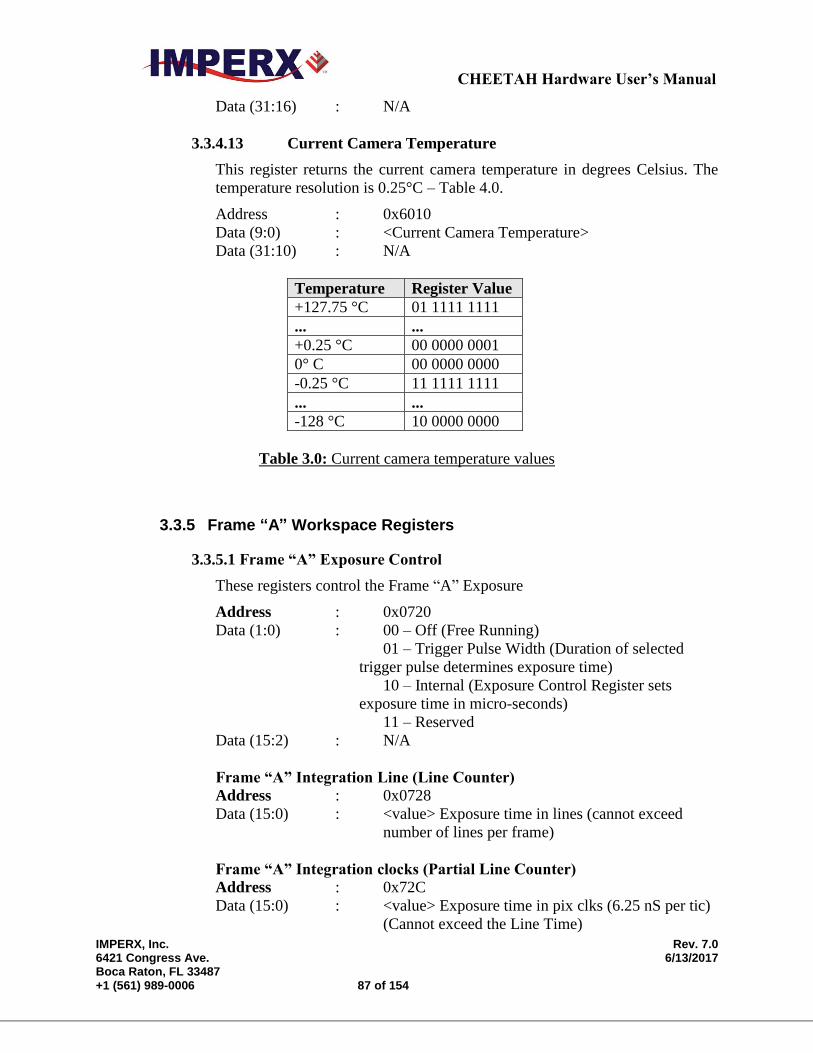
CHEETAH Hardware User’s Manual
IMPERX, Inc. Rev. 7.0 6421 Congress Ave. 6/13/2017 Boca Raton, FL 33487 +1 (561) 989-0006 87 of 154
Data (31:16) : N/A
3.3.4.13 Current Camera Temperature
This register returns the current camera temperature in degrees Celsius. The
temperature resolution is 0.25°C – Table 4.0.
Address : 0x6010
Data (9:0) : <Current Camera Temperature>
Data (31:10) : N/A
Temperature Register Value
+127.75 °C 01 1111 1111
... ...
+0.25 °C 00 0000 0001
0° C 00 0000 0000
-0.25 °C 11 1111 1111
... ...
-128 °C 10 0000 0000
Table 3.0: Current camera temperature values
3.3.5 Frame “A” Workspace Registers
3.3.5.1 Frame “A” Exposure Control
These registers control the Frame “A” Exposure
Address : 0x0720
Data (1:0) : 00 – Off (Free Running)
01 – Trigger Pulse Width (Duration of selected
trigger pulse determines exposure time)
10 – Internal (Exposure Control Register sets
exposure time in micro-seconds)
11 – Reserved
Data (15:2) : N/A
Frame “A” Integration Line (Line Counter)
Address : 0x0728
Data (15:0) : <value> Exposure time in lines (cannot exceed
number of lines per frame)
Frame “A” Integration clocks (Partial Line Counter)
Address : 0x72C
Data (15:0) : <value> Exposure time in pix clks (6.25 nS per tic)
(Cannot exceed the Line Time)
CHEETAH Hardware User’s Manual
IMPERX, Inc. Rev. 7.0 6421 Congress Ave. 6/13/2017 Boca Raton, FL 33487 +1 (561) 989-0006 88 of 154
3.3.5.2 Frame “A” Fixed Frame Period Enable
This register enables the Frame A Fixed Frame Period
Address : 0x0700
Data (0) : 0 – disable
1 – enable
Data (31:1) : N/A
3.3.5.3 Frame “A” Fixed Frame Period (Adds V-blanking lines)
This register sets the Frame “A” period
Address : 0x0704
Data (15:0) : <value> frame period in lines (65,535 maximum)
Data (31:16) : N/A
3.3.5.4 Frame “A” Line Time
This register sets the Frame “A” line time by adding additional clocks to each
line readout. Frame “A” line time must be greater than or equal to Minimum
Frame “A” line time is specified in Register 60B0. Each pixel clock is 6.25nS.
Address : 0x0710
Data (15:0) : <value> line time in pixel clks (65,535 maximum)
Data (31:16) : N/A
3.3.5.5 Frame “A” Area of Interest
These set of registers defines the Area of Interest and sets the appropriate
window size and offset in horizontal and vertical direction.
Frame “A” AOI Horizontal Offset
Address : 0x0008
Data (11:0) : <value> AOI horizontal offset (multiple of 8)
Data (31:12) : N/A
Frame “A” AOI Horizontal Width
Address : 0x000C
Data (12:0) : <value> AOI horizontal width (multiple of 8)
Data (31:13) : N/A
Frame “A” AOI Vertical Offset
Address : 0x0000
Data (11:0) : <value> AOI vertical offset (multiple of 2)
Data (31:12) : N/A
CHEETAH Hardware User’s Manual
IMPERX, Inc. Rev. 7.0 6421 Congress Ave. 6/13/2017 Boca Raton, FL 33487 +1 (561) 989-0006 89 of 154
Frame “A” AOI Vertical Height
Address : 0x0004
Data (11:0) : <value> AOI vertical height (multiple of 2)
Data (31:12) : N/A
3.3.5.6 Frame “A” Decimation (Averaging or Subsampling)
Frame “A” Decimation Mode
This register sets Frame “A” decimation mode: Averaging or Subsampling
Address : 0x073C
Data (1:0) : 00 – decimation off
01 – Subsampling enable
10 – Averaging enable
11 – N/A
Data (31:2) N/A
Frame “A” Subsampling Parameter N
This register sets Frame “A” subsampling parameter N
Address : 0x0740
Data (3:0) : <Frame “A” subsampling parameter N value>
Data (31:4) : N/A
Frame “A” Subsampling Parameter M
This register sets the Frame “A” subsampling parameter M. (M>N)
Address : 0x0744
Data (3:0) : <Frame “A” subsampling parameter M value>
Data (31:4) : N/A
Frame “A” Averaging Type
This register sets the Frame A averaging level.
Address : 0x0778
Data (0) : 0 – 4 into 1
1 – 9 into 1
CHEETAH Hardware User’s Manual
IMPERX, Inc. Rev. 7.0 6421 Congress Ave. 6/13/2017 Boca Raton, FL 33487 +1 (561) 989-0006 90 of 154
Data (31:1) : N/A
3.3.5.7 Frame “A” Black Level
This register controls the Frame A Black Level.
Address : 0x0050
Data (13:0) : <value> Target Black Level in DN
Data (15:14) : N/A
3.3.5.8 Frame “A” Analog & Digital Gain
Frame “A” Analog Gain
This register controls the Frame A analog gains. Analog gains should always
be applied before digital gain.
Address : 0x0748
Data (5:0) : < analog gain value>
Data (31:6) : N/A
Frame “A” Digital Gain (Fine Control)
This register sets the Frame “A” digital gain fine control
Address : 0x074C
Data (5:0) : <digital gain fine value>
Data (31:6) : N/A
Frame “A” Digital Gain (Course Control)
This register sets Frame “A” Course Digital Gain
Address : 0x0750
Data (1:0) : 00 - Course gain 1x to 2x
01 - Course gain 2x to 4x
10 – Course gain 4x to 8x
11 – Course gain 8x to 15x
Data (31:2) : N/A
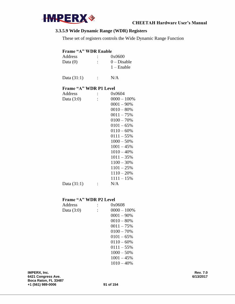
CHEETAH Hardware User’s Manual
IMPERX, Inc. Rev. 7.0 6421 Congress Ave. 6/13/2017 Boca Raton, FL 33487 +1 (561) 989-0006 91 of 154
3.3.5.9 Wide Dynamic Range (WDR) Registers
These set of registers controls the Wide Dynamic Range Function
Frame “A” WDR Enable
Address : 0x0600
Data (0) : 0 – Disable
1 – Enable
Data (31:1) : N/A
Frame “A” WDR P1 Level
Address : 0x0604
Data (3:0) : 0000 – 100%
0001 – 90%
0010 – 80%
0011 – 75%
0100 – 70%
0101 – 65%
0110 – 60%
0111 – 55%
1000 – 50%
1001 – 45%
1010 – 40%
1011 – 35%
1100 – 30%
1101 – 25%
1110 – 20%
1111 – 15%
Data (31:1) : N/A
Frame “A” WDR P2 Level
Address : 0x0608
Data (3:0) : 0000 – 100%
0001 – 90%
0010 – 80%
0011 – 75%
0100 – 70%
0101 – 65%
0110 – 60%
0111 – 55%
1000 – 50%
1001 – 45%
1010 – 40%

CHEETAH Hardware User’s Manual
IMPERX, Inc. Rev. 7.0 6421 Congress Ave. 6/13/2017 Boca Raton, FL 33487 +1 (561) 989-0006 92 of 154
1011 – 35%
1100 – 30%
1101 – 25%
1110 – 20%
1111 – 15%
Data (31:1) : N/A
Frame “A” WDR P3 Level
Address : 0x060C
Data (3:0) : 0000 – 100%
0001 – 90%
0010 – 80%
0011 – 75%
0100 – 70%
0101 – 65%
0110 – 60%
0111 – 55%
1000 – 50%
1001 – 45%
1010 – 40%
1011 – 35%
1100 – 30%
1101 – 25%
1110 – 20%
1111 – 15%
Data (31:1) : N/A
Frame “A” WDR E1 (Bright Pixel exposure period)
Address : 0x0610
Data (19:0) : <value> E1 exposure time in micro-sec., 1 sec max
Data (31:20) : N/A
Frame “A” WDR E2 (Very-Bright Pixel Exposure period)
Address : 0x0614
Data (19:0) : <value> E2 exposure time in micro-sec., 1 sec max
Data (31:20) : N/A
Frame “A” WDR E3 (Ultra-Bright Pixel Exposure period)
Address : 0x0660
Data (19:0) : <value> E3 exposure time in micro-sec., 1 sec max
Data (31:20) : N/A
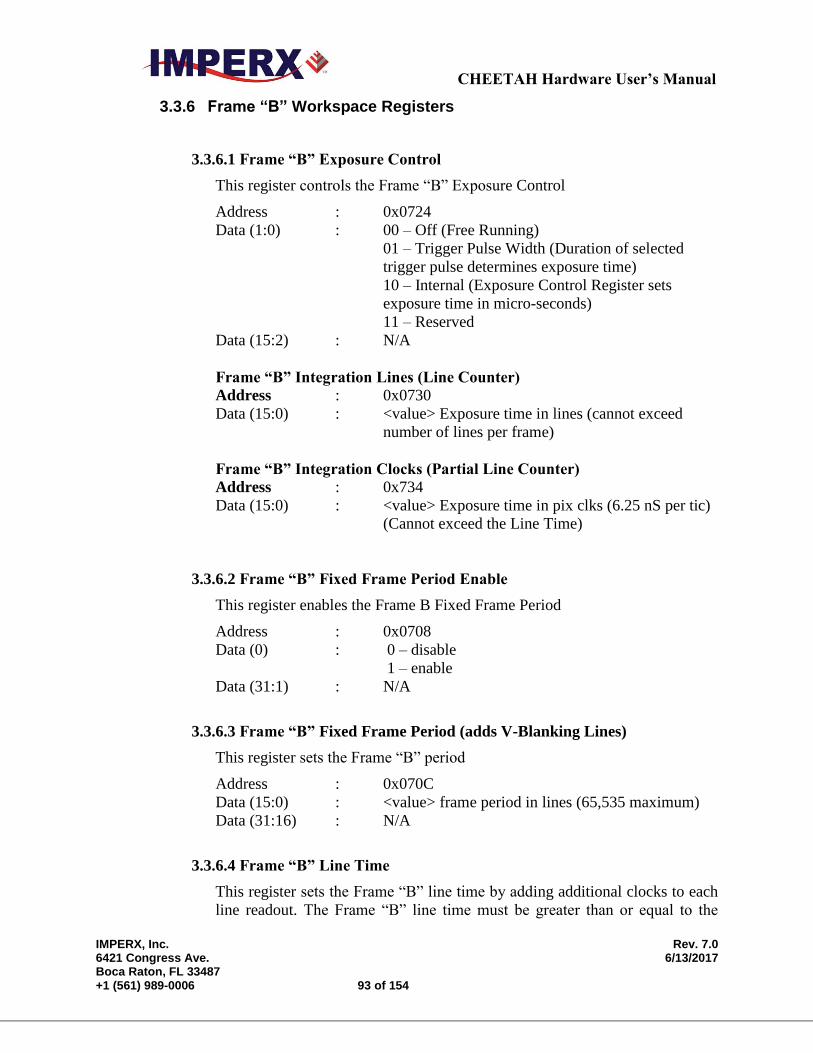
CHEETAH Hardware User’s Manual
IMPERX, Inc. Rev. 7.0 6421 Congress Ave. 6/13/2017 Boca Raton, FL 33487 +1 (561) 989-0006 93 of 154
3.3.6 Frame “B” Workspace Registers
3.3.6.1 Frame “B” Exposure Control
This register controls the Frame “B” Exposure Control
Address : 0x0724
Data (1:0) : 00 – Off (Free Running)
01 – Trigger Pulse Width (Duration of selected
trigger pulse determines exposure time)
10 – Internal (Exposure Control Register sets
exposure time in micro-seconds)
11 – Reserved
Data (15:2) : N/A
Frame “B” Integration Lines (Line Counter)
Address : 0x0730
Data (15:0) : <value> Exposure time in lines (cannot exceed
number of lines per frame)
Frame “B” Integration Clocks (Partial Line Counter)
Address : 0x734
Data (15:0) : <value> Exposure time in pix clks (6.25 nS per tic)
(Cannot exceed the Line Time)
3.3.6.2 Frame “B” Fixed Frame Period Enable
This register enables the Frame B Fixed Frame Period
Address : 0x0708
Data (0) : 0 – disable
1 – enable
Data (31:1) : N/A
3.3.6.3 Frame “B” Fixed Frame Period (adds V-Blanking Lines)
This register sets the Frame “B” period
Address : 0x070C
Data (15:0) : <value> frame period in lines (65,535 maximum)
Data (31:16) : N/A
3.3.6.4 Frame “B” Line Time
This register sets the Frame “B” line time by adding additional clocks to each
line readout. The Frame “B” line time must be greater than or equal to the
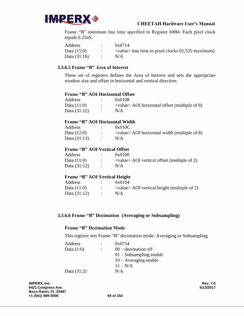
CHEETAH Hardware User’s Manual
IMPERX, Inc. Rev. 7.0 6421 Congress Ave. 6/13/2017 Boca Raton, FL 33487 +1 (561) 989-0006 94 of 154
Frame “B” minimum line time specified in Register 60B4. Each pixel clock
equals 6.25nS.
Address : 0x0714
Data (15:0) : <value> line time in pixel clocks 65,535 maximum)
Data (31:16) : N/A
3.3.6.5 Frame “B” Area of Interest
These set of registers defines the Area of Interest and sets the appropriate
window size and offset in horizontal and vertical direction.
Frame “B” AOI Horizontal Offset
Address : 0x0108
Data (11:0) : <value> AOI horizontal offset (multiple of 8)
Data (31:12) : N/A
Frame “B” AOI Horizontal Width
Address : 0x010C
Data (12:0) : <value> AOI horizontal width (multiple of 8)
Data (31:13) : N/A
Frame “B” AOI Vertical Offset
Address : 0x0100
Data (11:0) : <value> AOI vertical offset (multiple of 2)
Data (31:12) : N/A
Frame “B” AOI Vertical Height
Address : 0x0104
Data (11:0) : <value> AOI vertical height (multiple of 2)
Data (31:12) : N/A
3.3.6.6 Frame “B” Decimation (Averaging or Subsampling)
Frame “B” Decimation Mode
This register sets Frame “B” decimation mode: Averaging or Subsampling
Address : 0x0754
Data (1:0) : 00 – decimation off
01 – Subsampling enable
10 – Averaging enable
11 – N/A
Data (31:2) N/A
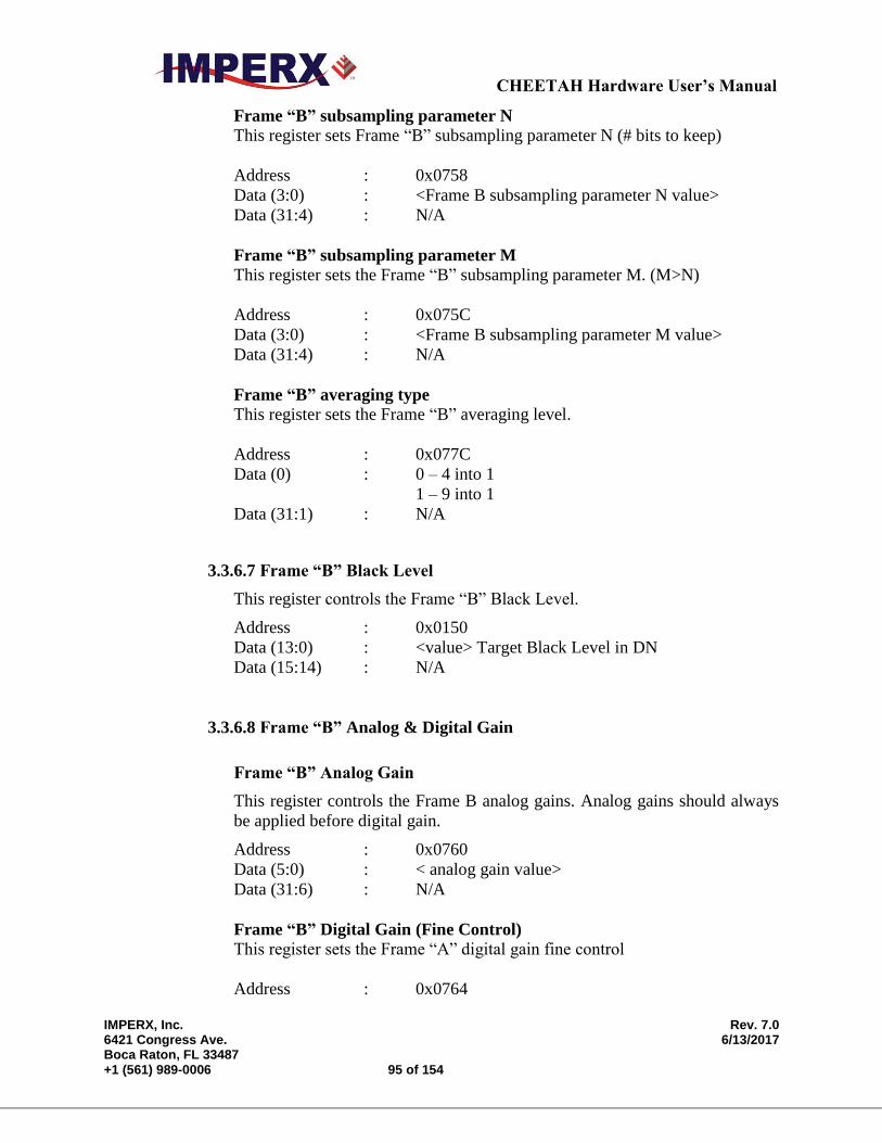
CHEETAH Hardware User’s Manual
IMPERX, Inc. Rev. 7.0 6421 Congress Ave. 6/13/2017 Boca Raton, FL 33487 +1 (561) 989-0006 95 of 154
Frame “B” subsampling parameter N
This register sets Frame “B” subsampling parameter N (# bits to keep)
Address : 0x0758
Data (3:0) : <Frame B subsampling parameter N value>
Data (31:4) : N/A
Frame “B” subsampling parameter M
This register sets the Frame “B” subsampling parameter M. (M>N)
Address : 0x075C
Data (3:0) : <Frame B subsampling parameter M value>
Data (31:4) : N/A
Frame “B” averaging type
This register sets the Frame “B” averaging level.
Address : 0x077C
Data (0) : 0 – 4 into 1
1 – 9 into 1
Data (31:1) : N/A
3.3.6.7 Frame “B” Black Level
This register controls the Frame “B” Black Level.
Address : 0x0150
Data (13:0) : <value> Target Black Level in DN
Data (15:14) : N/A
3.3.6.8 Frame “B” Analog & Digital Gain
Frame “B” Analog Gain
This register controls the Frame B analog gains. Analog gains should always
be applied before digital gain.
Address : 0x0760
Data (5:0) : < analog gain value>
Data (31:6) : N/A
Frame “B” Digital Gain (Fine Control)
This register sets the Frame “A” digital gain fine control
Address : 0x0764
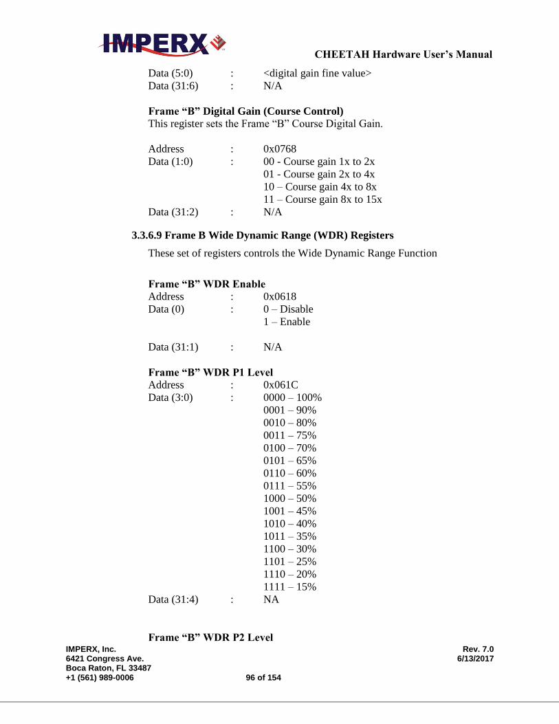
CHEETAH Hardware User’s Manual
IMPERX, Inc. Rev. 7.0 6421 Congress Ave. 6/13/2017 Boca Raton, FL 33487 +1 (561) 989-0006 96 of 154
Data (5:0) : <digital gain fine value>
Data (31:6) : N/A
Frame “B” Digital Gain (Course Control)
This register sets the Frame “B” Course Digital Gain.
Address : 0x0768
Data (1:0) : 00 - Course gain 1x to 2x
01 - Course gain 2x to 4x
10 – Course gain 4x to 8x
11 – Course gain 8x to 15x
Data (31:2) : N/A
3.3.6.9 Frame B Wide Dynamic Range (WDR) Registers
These set of registers controls the Wide Dynamic Range Function
Frame “B” WDR Enable
Address : 0x0618
Data (0) : 0 – Disable
1 – Enable
Data (31:1) : N/A
Frame “B” WDR P1 Level
Address : 0x061C
Data (3:0) : 0000 – 100%
0001 – 90%
0010 – 80%
0011 – 75%
0100 – 70%
0101 – 65%
0110 – 60%
0111 – 55%
1000 – 50%
1001 – 45%
1010 – 40%
1011 – 35%
1100 – 30%
1101 – 25%
1110 – 20%
1111 – 15%
Data (31:4) : NA
Frame “B” WDR P2 Level
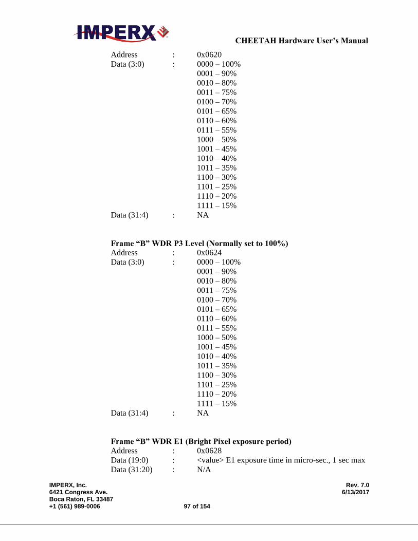
CHEETAH Hardware User’s Manual
IMPERX, Inc. Rev. 7.0 6421 Congress Ave. 6/13/2017 Boca Raton, FL 33487 +1 (561) 989-0006 97 of 154
Address : 0x0620
Data (3:0) : 0000 – 100%
0001 – 90%
0010 – 80%
0011 – 75%
0100 – 70%
0101 – 65%
0110 – 60%
0111 – 55%
1000 – 50%
1001 – 45%
1010 – 40%
1011 – 35%
1100 – 30%
1101 – 25%
1110 – 20%
1111 – 15%
Data (31:4) : NA
Frame “B” WDR P3 Level (Normally set to 100%)
Address : 0x0624
Data (3:0) : 0000 – 100%
0001 – 90%
0010 – 80%
0011 – 75%
0100 – 70%
0101 – 65%
0110 – 60%
0111 – 55%
1000 – 50%
1001 – 45%
1010 – 40%
1011 – 35%
1100 – 30%
1101 – 25%
1110 – 20%
1111 – 15%
Data (31:4) : NA
Frame “B” WDR E1 (Bright Pixel exposure period)
Address : 0x0628
Data (19:0) : <value> E1 exposure time in micro-sec., 1 sec max
Data (31:20) : N/A
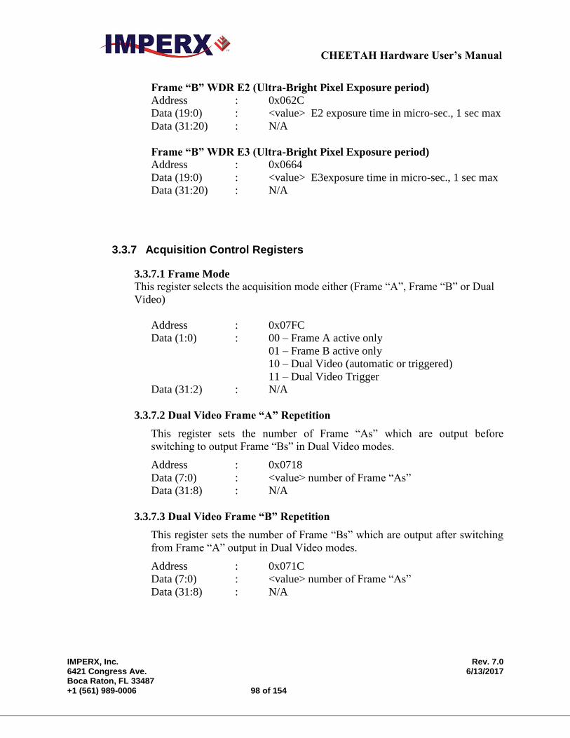
CHEETAH Hardware User’s Manual
IMPERX, Inc. Rev. 7.0 6421 Congress Ave. 6/13/2017 Boca Raton, FL 33487 +1 (561) 989-0006 98 of 154
Frame “B” WDR E2 (Ultra-Bright Pixel Exposure period)
Address : 0x062C
Data (19:0) : <value> E2 exposure time in micro-sec., 1 sec max
Data (31:20) : N/A
Frame “B” WDR E3 (Ultra-Bright Pixel Exposure period)
Address : 0x0664
Data (19:0) : <value> E3exposure time in micro-sec., 1 sec max
Data (31:20) : N/A
3.3.7 Acquisition Control Registers
3.3.7.1 Frame Mode
This register selects the acquisition mode either (Frame “A”, Frame “B” or Dual
Video)
Address : 0x07FC
Data (1:0) : 00 – Frame A active only
01 – Frame B active only
10 – Dual Video (automatic or triggered)
11 – Dual Video Trigger
Data (31:2) : N/A
3.3.7.2 Dual Video Frame “A” Repetition
This register sets the number of Frame “As” which are output before
switching to output Frame “Bs” in Dual Video modes.
Address : 0x0718
Data (7:0) : <value> number of Frame “As”
Data (31:8) : N/A
3.3.7.3 Dual Video Frame “B” Repetition
This register sets the number of Frame “Bs” which are output after switching
from Frame “A” output in Dual Video modes.
Address : 0x071C
Data (7:0) : <value> number of Frame “As”
Data (31:8) : N/A
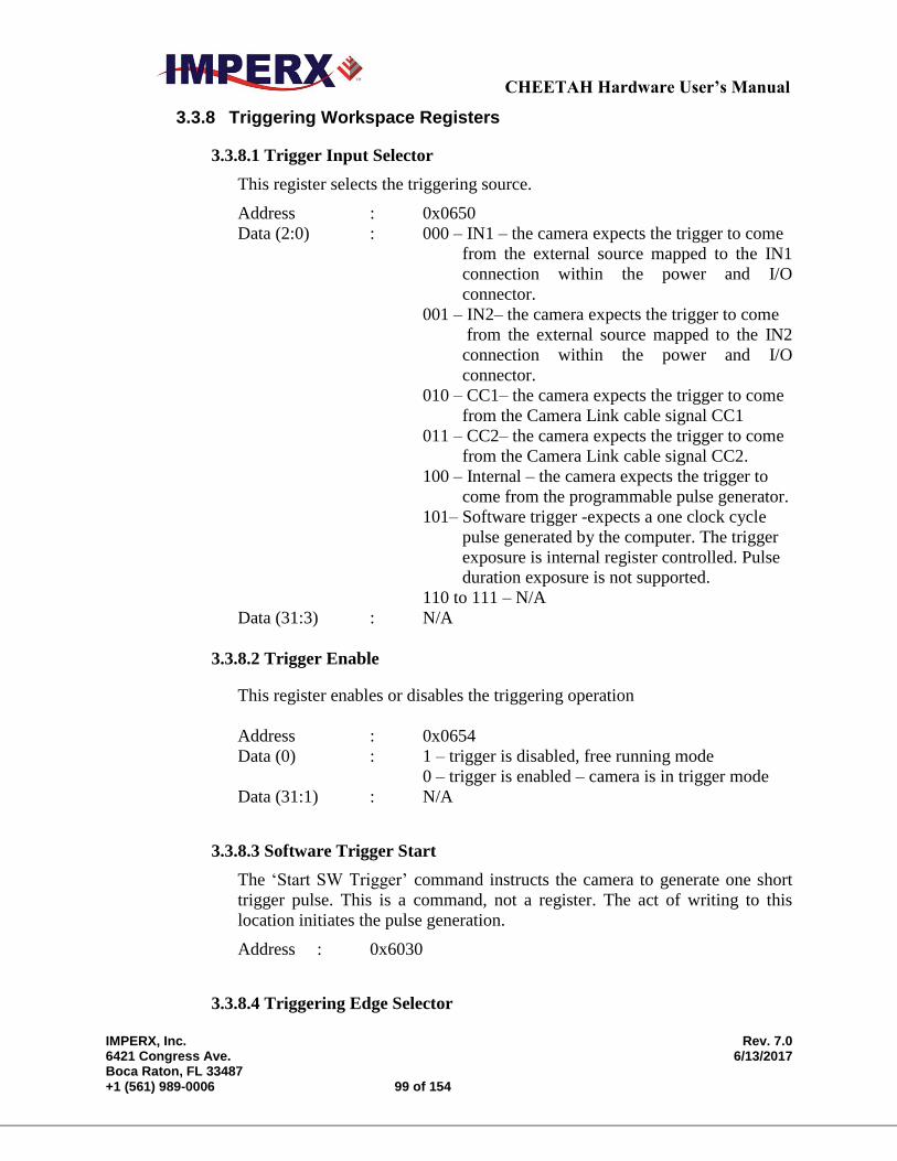
CHEETAH Hardware User’s Manual
IMPERX, Inc. Rev. 7.0 6421 Congress Ave. 6/13/2017 Boca Raton, FL 33487 +1 (561) 989-0006 99 of 154
3.3.8 Triggering Workspace Registers
3.3.8.1 Trigger Input Selector
This register selects the triggering source.
Address : 0x0650
Data (2:0) : 000 – IN1 – the camera expects the trigger to come
from the external source mapped to the IN1
connection within the power and I/O
connector.
001 – IN2– the camera expects the trigger to come
from the external source mapped to the IN2
connection within the power and I/O
connector.
010 – CC1– the camera expects the trigger to come
from the Camera Link cable signal CC1
011 – CC2– the camera expects the trigger to come
from the Camera Link cable signal CC2.
100 – Internal – the camera expects the trigger to
come from the programmable pulse generator.
101– Software trigger -expects a one clock cycle
pulse generated by the computer. The trigger
exposure is internal register controlled. Pulse
duration exposure is not supported.
110 to 111 – N/A
Data (31:3) : N/A
3.3.8.2 Trigger Enable
This register enables or disables the triggering operation
Address : 0x0654
Data (0) : 1 – trigger is disabled, free running mode
0 – trigger is enabled – camera is in trigger mode
Data (31:1) : N/A
3.3.8.3 Software Trigger Start
The ‘Start SW Trigger’ command instructs the camera to generate one short
trigger pulse. This is a command, not a register. The act of writing to this
location initiates the pulse generation.
Address : 0x6030
3.3.8.4 Triggering Edge Selector
CHEETAH Hardware User’s Manual
IMPERX, Inc. Rev. 7.0 6421 Congress Ave. 6/13/2017 Boca Raton, FL 33487 +1 (561) 989-0006 100 of 154
This register selects the triggering edge – Rising or Falling.
Address : 0x0658
Data (0) : 0 – rising edge
1 – falling edge
Data (31:1) : N/A
3.3.8.5 Trigger De-bounce Time
This register selects the trigger signal de-bounce time. Any subsequent trigger
signals coming to the camera within the de-bounce time interval will be
ignored.
Address : 0x065C
Data (2:0) : 000 – no de-bounce
100 – 10 s de-bounce time
101 – 50 s de-bounce time
001 – 100 s de-bounce time
110 – 500 s de-bounce time
010 – 1.0 ms de-bounce time
111 – 5.0 ms de-bounce time
011 – 10.0 ms de-bounce time
Data (31:3) : N/A
3.3.9 Strobe Control Registers
These registers enable and control the position and pulse width of the two
available strobes. The strobe signal is mapped to one or both of the available
strobe outputs.
3.3.9.1 Strobe 1 Enable
This register enables Strobe 1
Address : 0x0630
Data (1:0) : 00 – disable
01 – enable for Frame A only (exposure period)
10 – enable for Frame B only (exposure period)
11 – enable for both Frame A and B
Data (31:2) : N/A
3.3.9.2 Strobe 1 Reference Select
This register sets the reference for the strobe 1 Start.
Address : 0x0634
Data (0) : 0 – Exposure Start
CHEETAH Hardware User’s Manual
IMPERX, Inc. Rev. 7.0 6421 Congress Ave. 6/13/2017 Boca Raton, FL 33487 +1 (561) 989-0006 101 of 154
1 – Readout Start
Data (31:1) : N/A
3.3.9.3 Strobe 1 Delay
This register sets the strobe 1 delay from the selected Reference.
Address : 0x0638
Data (19:0) : <value> – delay in micro sec., 1 sec max.
Data (31:20) : N/A
3.3.9.4 Strobe 1 Width
This register sets the strobe 1 pulse duration.
Address : 0x063C
Data (19:0) : <value> –width in micro sec., 1 sec max.
Data (31:20) : N/A
3.3.9.5 Strobe 2 Enable
This register enables Strobe 2
Address : 0x0640
Data (1:0) : 00 – disable
01 – enable for Frame A only (exposure period)
10 – enable for Frame B only (exposure period)
11 – enable for both Frame A and B
Data (31:2) : N/A
3.3.9.6 Strobe 2 Reference Select
This register sets the reference for the strobe 2 start.
Address : 0x0644
Data (0) : 0 – Exposure Start
1 – Readout Start
Data (31:1) : N/A
3.3.9.7 Strobe 2 Delay
This register sets the strobe 2 delay from the selected Reference
Address : 0x0648
Data (19:0) : <value> – delay in micro sec., 1 sec max.
Data (31:20) : N/A
3.3.9.8 Strobe 2 Width
This register sets the strobe 2 pulse duration.
CHEETAH Hardware User’s Manual
IMPERX, Inc. Rev. 7.0 6421 Congress Ave. 6/13/2017 Boca Raton, FL 33487 +1 (561) 989-0006 102 of 154
Address : 0x064C
Data (19:0) : <value> – width in micro sec., 1 sec max.
Data (31:20) : N/A
3.3.10 Pulse Generator Workspace Registers
3.3.10.1 Pulse Generator Timing Granularity
This register sets the pulse generator main timing resolution. The main
resolution is in microseconds, and 4 granularity steps are possible – x1, x10,
x100, x1000 (x1000 is equal to 1ms timing resolution).
Address : 0x0690
Data (1:0) : 00 – x1
01 – x10
10 – x100
11 – x1000
Data (31:2) : N/A
3.3.10.2 Pulse Generator Pulse Width
This register sets the value of the pulse width in microseconds.
Address : 0x0694
Data (18:0) : <value> – pulse width in microseconds
Data (31:19) : N/A
3.3.10.3 Pulse Generator Pulse Period
This register sets the value of the pulse period in microseconds.
Address : 0x0698
Data (19:0) : <value> – pulse width in microseconds
Data (31:20) : N/A
3.3.10.4 Pulse Generator Number of Pulses
This register sets the number of the pulses generated when the Pulse
Generator Mode is set to Burst Mode (discrete number of pulses)
Address : 0x069C
Data (15:0) : <value> – number of discrete pulses
Data (31:16) : N/A
3.3.10.5 Pulse Generator Mode
This register sets the Pulse Generator to either continuous mode or burst
mode.
CHEETAH Hardware User’s Manual
IMPERX, Inc. Rev. 7.0 6421 Congress Ave. 6/13/2017 Boca Raton, FL 33487 +1 (561) 989-0006 103 of 154
Address : 0x06A4
Data (0) : 0 – Continuous Mode - continuous pulse generation
1 – Burst Mode - Generate discrete number of
pulses (see Pulse Generator Number of Pulses
section, register 0x069C)
Data(31:1) : N/A
3.3.10.6 Pulse Generator Enable
This register enables the pulse generator.
Address : 0x06A0
Data (0) : 0 – disable pulse generator operation
1 – enable pulse generator operation
Data (31:1) : N/A
3.3.11 Test Pattern Workspace Registers
3.3.11.1 Test Mode Select
This register selects the test mode pattern.
Address : 0x0428
Data (3:0) : 000 – no test pattern
001 – steady horizontal image ramp
010 – steady vertical image ramp
011 – moving horizontal image ramp
100 – moving vertical image ramp
101– crosshairs superimposed over live image
110 – reserved
111 – reserved
Data (31:4) : N/A
3.3.12 Input/output Workspace Registers
3.3.12.1 OUT1 Output Polarity
This register sets the polarity (active Low or High) for the OUT1 output.
Address : 0x0680
Data (0) : 0 – active LOW
1 – active HIGH

CHEETAH Hardware User’s Manual
IMPERX, Inc. Rev. 7.0 6421 Congress Ave. 6/13/2017 Boca Raton, FL 33487 +1 (561) 989-0006 104 of 154
Data (31:1) : N/A
3.3.12.2 OUT1 Output Mapping
This register maps the various internal signals to OUT1 camera output.
Address : 0x0684
Data (2:0) : 000 – no mapping
001 – trigger pulse
010 – pulse generator
011 – Strobe 1
100 – Strobe 2
1XX – reserved
Data (31:3) : N/A
3.3.12.3 OUT2 Output Polarity
This register sets the polarity (active Low or High) for the OUT2 output.
Address : 0x0688
Data (0) : 0 – active LOW
1 – active HIGH
Data (31:1) : N/A
3.3.12.4 OUT2 Output Mapping
This register maps the various internal signals to OUT2 camera output.
Address : 0x068C
Data (2:0) : 000 – no mapping
001 – trigger pulse
010 – pulse generator
011 – Strobe 1
100 – Strobe 2
1XX – Reserved
Data (31:3) : N/A
3.3.13 Data Output Bit Depth/Format Selector
This register selects the bit depth output for the camera.
Address : 0x040C
Data (1:0) : 00 – 8-bit
01 – 10-bit
10 – 12-bit
Data (31:2) : N/A
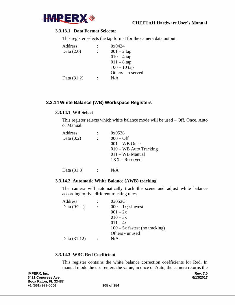
CHEETAH Hardware User’s Manual
IMPERX, Inc. Rev. 7.0 6421 Congress Ave. 6/13/2017 Boca Raton, FL 33487 +1 (561) 989-0006 105 of 154
3.3.13.1 Data Format Selector
This register selects the tap format for the camera data output.
Address : 0x0424
Data (2:0) : 001 – 2 tap
010 – 4 tap
011 – 8 tap
100 – 10 tap
Others – reserved
Data (31:2) : N/A
3.3.14 White Balance (WB) Workspace Registers
3.3.14.1 WB Select
This register selects which white balance mode will be used – Off, Once, Auto
or Manual.
Address : 0x0538
Data (0:2) : 000 – Off
001 – WB Once
010 – WB Auto Tracking
011 – WB Manual
1XX – Reserved
Data (31:3) : N/A
3.3.14.2 Automatic White Balance (AWB) tracking
The camera will automatically track the scene and adjust white balance
according to five different tracking rates.
Address : 0x053C
Data (0:2 ) : 000 – 1x; slowest
001 – 2x
010 – 3x
011 – 4x
100 – 5x fastest (no tracking)
Others - unused
Data (31:12) : N/A
3.3.14.3 WBC Red Coefficient
This register contains the white balance correction coefficients for Red. In
manual mode the user enters the value, in once or Auto, the camera returns the
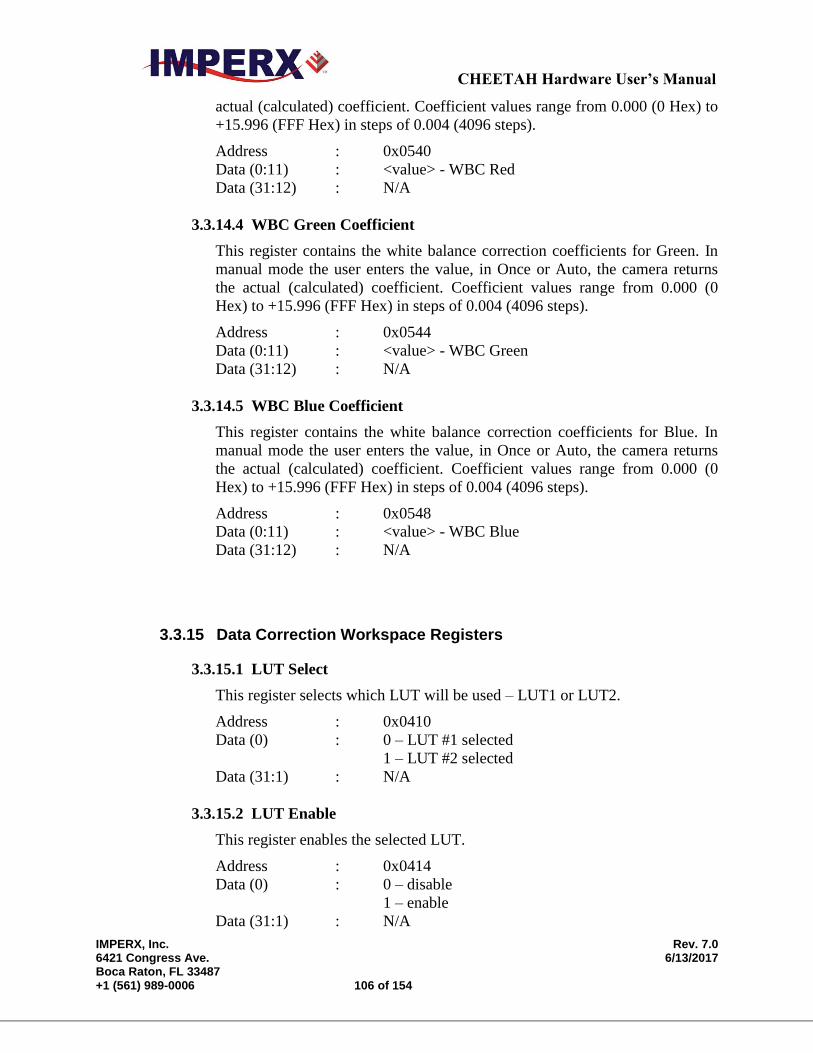
CHEETAH Hardware User’s Manual
IMPERX, Inc. Rev. 7.0 6421 Congress Ave. 6/13/2017 Boca Raton, FL 33487 +1 (561) 989-0006 106 of 154
actual (calculated) coefficient. Coefficient values range from 0.000 (0 Hex) to
+15.996 (FFF Hex) in steps of 0.004 (4096 steps).
Address : 0x0540
Data (0:11) : <value> - WBC Red
Data (31:12) : N/A
3.3.14.4 WBC Green Coefficient
This register contains the white balance correction coefficients for Green. In
manual mode the user enters the value, in Once or Auto, the camera returns
the actual (calculated) coefficient. Coefficient values range from 0.000 (0
Hex) to +15.996 (FFF Hex) in steps of 0.004 (4096 steps).
Address : 0x0544
Data (0:11) : <value> - WBC Green
Data (31:12) : N/A
3.3.14.5 WBC Blue Coefficient
This register contains the white balance correction coefficients for Blue. In
manual mode the user enters the value, in Once or Auto, the camera returns
the actual (calculated) coefficient. Coefficient values range from 0.000 (0
Hex) to +15.996 (FFF Hex) in steps of 0.004 (4096 steps).
Address : 0x0548
Data (0:11) : <value> - WBC Blue
Data (31:12) : N/A
3.3.15 Data Correction Workspace Registers
3.3.15.1 LUT Select
This register selects which LUT will be used – LUT1 or LUT2.
Address : 0x0410
Data (0) : 0 – LUT #1 selected
1 – LUT #2 selected
Data (31:1) : N/A
3.3.15.2 LUT Enable
This register enables the selected LUT.
Address : 0x0414
Data (0) : 0 – disable
1 – enable
Data (31:1) : N/A
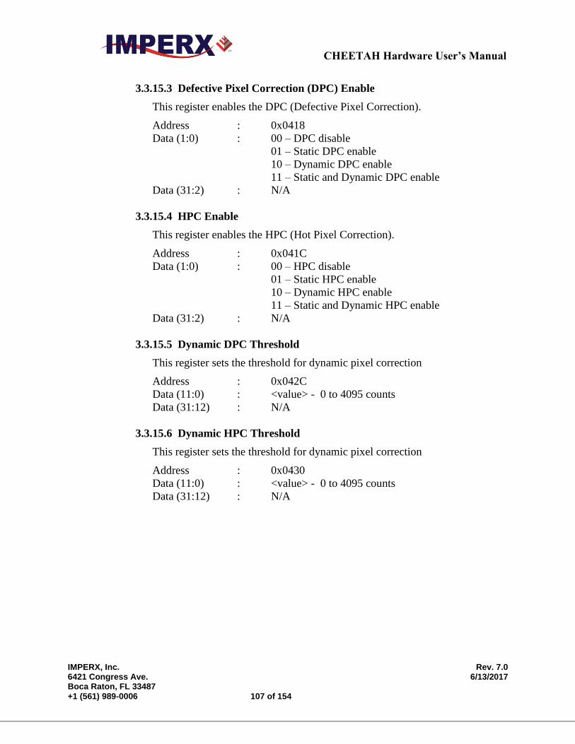
CHEETAH Hardware User’s Manual
IMPERX, Inc. Rev. 7.0 6421 Congress Ave. 6/13/2017 Boca Raton, FL 33487 +1 (561) 989-0006 107 of 154
3.3.15.3 Defective Pixel Correction (DPC) Enable
This register enables the DPC (Defective Pixel Correction).
Address : 0x0418
Data (1:0) : 00 – DPC disable
01 – Static DPC enable
10 – Dynamic DPC enable
11 – Static and Dynamic DPC enable
Data (31:2) : N/A
3.3.15.4 HPC Enable
This register enables the HPC (Hot Pixel Correction).
Address : 0x041C
Data (1:0) : 00 – HPC disable
01 – Static HPC enable
10 – Dynamic HPC enable
11 – Static and Dynamic HPC enable
Data (31:2) : N/A
3.3.15.5 Dynamic DPC Threshold
This register sets the threshold for dynamic pixel correction
Address : 0x042C
Data (11:0) : <value> - 0 to 4095 counts
Data (31:12) : N/A
3.3.15.6 Dynamic HPC Threshold
This register sets the threshold for dynamic pixel correction
Address : 0x0430
Data (11:0) : <value> - 0 to 4095 counts
Data (31:12) : N/A
CHEETAH Hardware User’s Manual
IMPERX, Inc. Rev. 7.0 6421 Congress Ave. 6/13/2017 Boca Raton, FL 33487 +1 (561) 989-0006 108 of 154
CHAPTER 4 Configurator for CameraLink
CHEETAH Configurator for CameraLink This chapter provides a quick reference to using the CHEETAH
Configurator camera configuration utility for the Camera Link series of
CHEETAH cameras.

CHEETAH Hardware User’s Manual
IMPERX, Inc. Rev. 7.0 6421 Congress Ave. 6/13/2017 Boca Raton, FL 33487 +1 (561) 989-0006 109 of 154
4.1 OVERVIEW
Camera configuration utility software and CHEETAH Camera Configurator
(CamConfig) are provided with each camera. After installing the program, the user can
program the camera, change its settings and save the settings in a file or in the camera.
The configuration utility includes an interactive help file, which will guide you through
the camera setup.
4.2 DISCOVERY PROCEDURE
The Imperx camera configurator utility (CamConfig) provides an intelligent, automated
method of ‘discovering’ and ‘searching’ all available UART components in your PC and
allowing you to select the one connected to the CHEETAH camera. CamConfig expects
the frame grabber’s serial interface DLL clserXXX.dll file to be located in
C:\Windows\System32. If the CamConfig software does not find your camera, it could be
because your frame grabber stored the clserXXX.dll file in a different directory on your
computer. You will need to locate the file and move it to C:\Windows\System32.
To search for the frame grabber’s clserXXX.dll file:
1. In Windows File Explore, click the C drive.
2. In the search field type clser* and press Enter.
3. After finding the appropriate file, move it to C:\Windows\System32.
The CamConfig engine not only finds the CamLink DLL port but also looks for any
available COM port installed on the PC as well. It will then communicate with each port
(.DLL and COM) and attempt to query the attached camera. After finding an attached
Imperx CHEETAH camera, CamConfig will read the ‘camera type’ information from the
camera. The CHEETAH camera name will appear in the list box, which includes all
DLLs, ports, and cameras discovered. The user can then select the DLL/port/camera of
interest by highlighting the entry and clicking the OK button. Clicking on the Rescan
Ports button causes the above discovery procedure to repeat. Note: the frame grabber has
to be Camera Link v1.0 (or later) compliant.
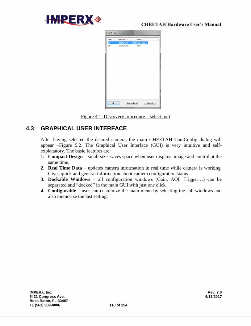
CHEETAH Hardware User’s Manual
IMPERX, Inc. Rev. 7.0 6421 Congress Ave. 6/13/2017 Boca Raton, FL 33487 +1 (561) 989-0006 110 of 154
Figure 4.1: Discovery procedure – select port
4.3 GRAPHICAL USER INTERFACE
After having selected the desired camera, the main CHEETAH CamConfig dialog will
appear –Figure 5.2. The Graphical User Interface (GUI) is very intuitive and self-
explanatory. The basic features are:
1. Compact Design – small size saves space when user displays image and control at the
same time.
2. Real Time Data – updates camera information in real time while camera is working.
Gives quick and general information about camera configuration status.
3. Dockable Windows – all configuration windows (Gain, AOI, Trigger…) can be
separated and “docked” in the main GUI with just one click.
4. Configurable – user can customize the main menu by selecting the sub windows and
also memorize the last setting.
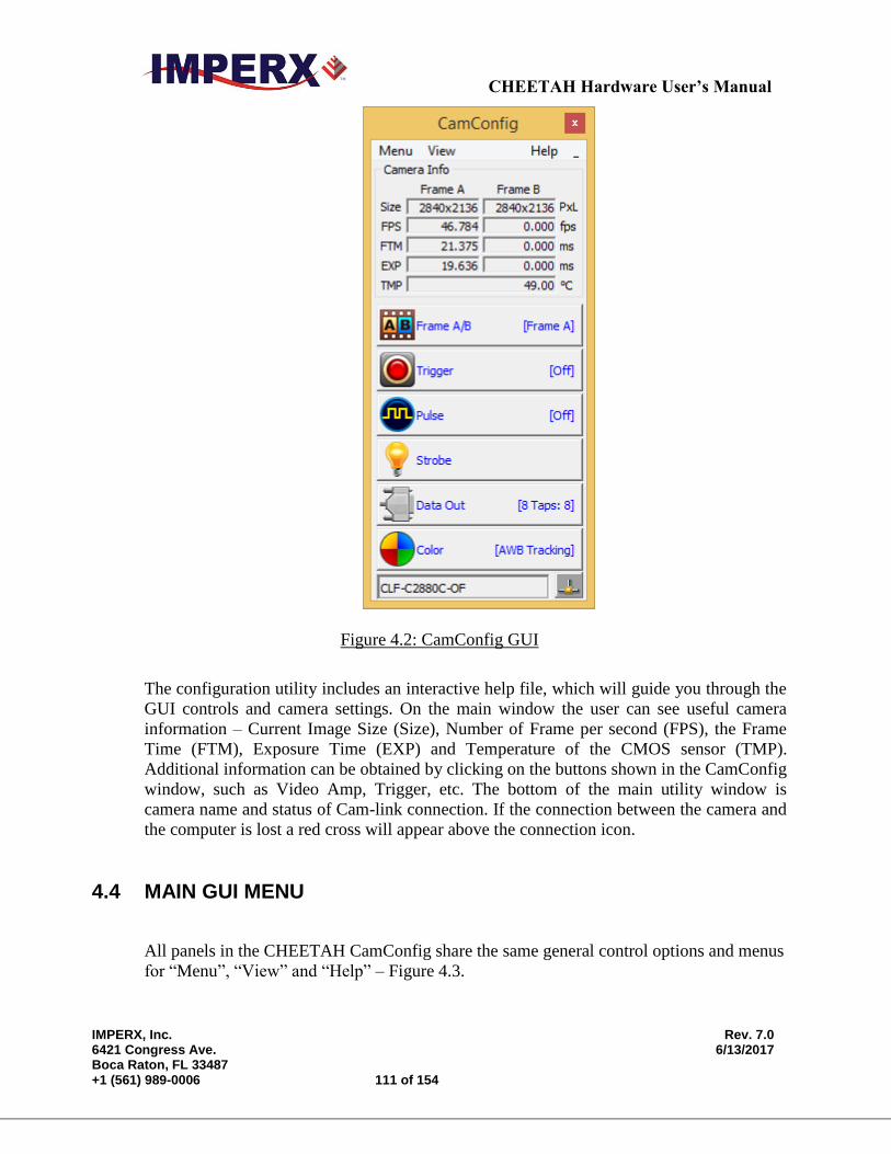
CHEETAH Hardware User’s Manual
IMPERX, Inc. Rev. 7.0 6421 Congress Ave. 6/13/2017 Boca Raton, FL 33487 +1 (561) 989-0006 111 of 154
Figure 4.2: CamConfig GUI
The configuration utility includes an interactive help file, which will guide you through the
GUI controls and camera settings. On the main window the user can see useful camera
information – Current Image Size (Size), Number of Frame per second (FPS), the Frame
Time (FTM), Exposure Time (EXP) and Temperature of the CMOS sensor (TMP).
Additional information can be obtained by clicking on the buttons shown in the CamConfig
window, such as Video Amp, Trigger, etc. The bottom of the main utility window is
camera name and status of Cam-link connection. If the connection between the camera and
the computer is lost a red cross will appear above the connection icon.
4.4 MAIN GUI MENU
All panels in the CHEETAH CamConfig share the same general control options and menus
for “Menu”, “View” and “Help” – Figure 4.3.
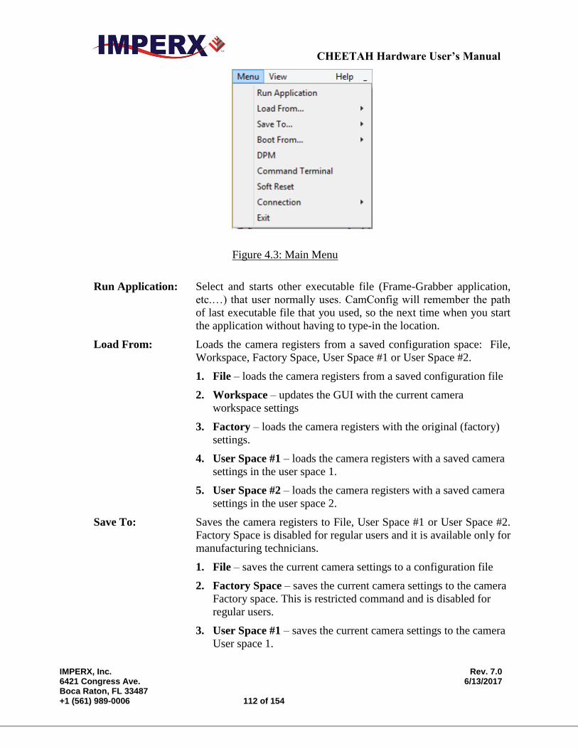
CHEETAH Hardware User’s Manual
IMPERX, Inc. Rev. 7.0 6421 Congress Ave. 6/13/2017 Boca Raton, FL 33487 +1 (561) 989-0006 112 of 154
Figure 4.3: Main Menu
Run Application: Select and starts other executable file (Frame-Grabber application,
etc.…) that user normally uses. CamConfig will remember the path
of last executable file that you used, so the next time when you start
the application without having to type-in the location.
Load From: Loads the camera registers from a saved configuration space: File,
Workspace, Factory Space, User Space #1 or User Space #2.
1. File – loads the camera registers from a saved configuration file
2. Workspace – updates the GUI with the current camera
workspace settings
3. Factory – loads the camera registers with the original (factory)
settings.
4. User Space #1 – loads the camera registers with a saved camera
settings in the user space 1.
5. User Space #2 – loads the camera registers with a saved camera
settings in the user space 2.
Save To: Saves the camera registers to File, User Space #1 or User Space #2.
Factory Space is disabled for regular users and it is available only for
manufacturing technicians.
1. File – saves the current camera settings to a configuration file
2. Factory Space – saves the current camera settings to the camera
Factory space. This is restricted command and is disabled for
regular users.
3. User Space #1 – saves the current camera settings to the camera
User space 1.
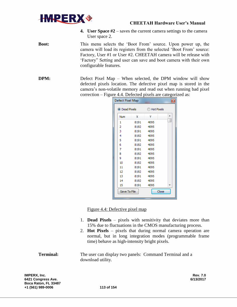
CHEETAH Hardware User’s Manual
IMPERX, Inc. Rev. 7.0 6421 Congress Ave. 6/13/2017 Boca Raton, FL 33487 +1 (561) 989-0006 113 of 154
4. User Space #2 – saves the current camera settings to the camera
User space 2.
Boot: This menu selects the ‘Boot From’ source. Upon power up, the
camera will load its registers from the selected ‘Boot From’ source:
Factory, User #1 or User #2. CHEETAH camera will be release with
‘Factory” Setting and user can save and boot camera with their own
configurable features.
DPM: Defect Pixel Map – When selected, the DPM window will show
defected pixels location. The defective pixel map is stored in the
camera’s non-volatile memory and read out when running bad pixel
correction – Figure 4.4. Defected pixels are categorized as:
Figure 4.4: Defective pixel map
1. Dead Pixels – pixels with sensitivity that deviates more than
15% due to fluctuations in the CMOS manufacturing process.
2. Hot Pixels – pixels that during normal camera operation are
normal, but in long integration modes (programmable frame
time) behave as high-intensity bright pixels.
Terminal: The user can display two panels: Command Terminal and a
download utility.
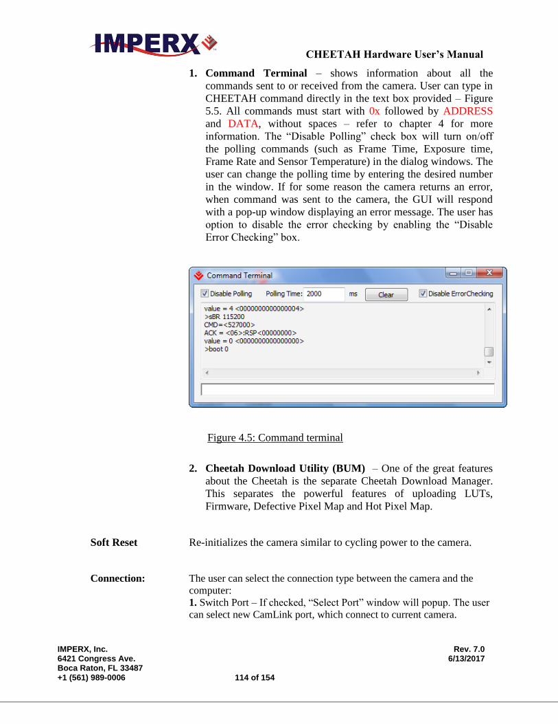
CHEETAH Hardware User’s Manual
IMPERX, Inc. Rev. 7.0 6421 Congress Ave. 6/13/2017 Boca Raton, FL 33487 +1 (561) 989-0006 114 of 154
1. Command Terminal – shows information about all the
commands sent to or received from the camera. User can type in
CHEETAH command directly in the text box provided – Figure
5.5. All commands must start with 0x followed by ADDRESS
and DATA, without spaces – refer to chapter 4 for more
information. The “Disable Polling” check box will turn on/off
the polling commands (such as Frame Time, Exposure time,
Frame Rate and Sensor Temperature) in the dialog windows. The
user can change the polling time by entering the desired number
in the window. If for some reason the camera returns an error,
when command was sent to the camera, the GUI will respond
with a pop-up window displaying an error message. The user has
option to disable the error checking by enabling the “Disable
Error Checking” box.
Figure 4.5: Command terminal
2. Cheetah Download Utility (BUM) – One of the great features
about the Cheetah is the separate Cheetah Download Manager.
This separates the powerful features of uploading LUTs,
Firmware, Defective Pixel Map and Hot Pixel Map.
Soft Reset Re-initializes the camera similar to cycling power to the camera.
Connection: The user can select the connection type between the camera and the
computer:
1. Switch Port – If checked, “Select Port” window will popup. The user
can select new CamLink port, which connect to current camera.
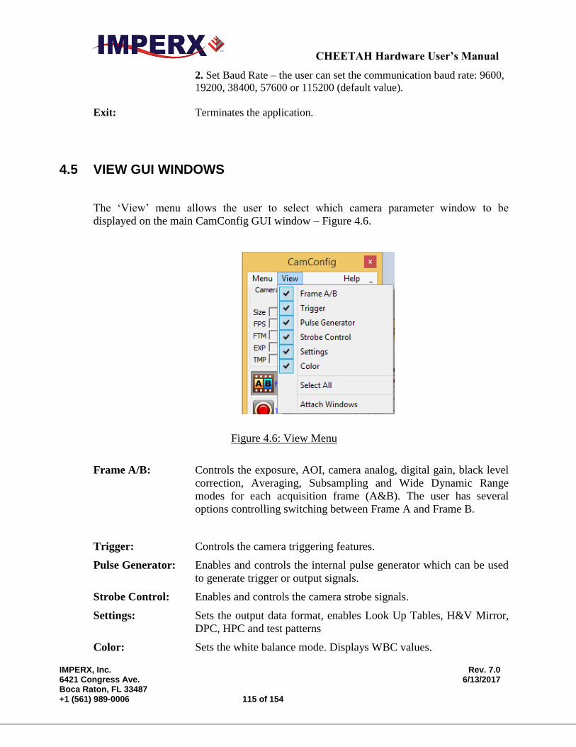
CHEETAH Hardware User’s Manual
IMPERX, Inc. Rev. 7.0 6421 Congress Ave. 6/13/2017 Boca Raton, FL 33487 +1 (561) 989-0006 115 of 154
2. Set Baud Rate – the user can set the communication baud rate: 9600,
19200, 38400, 57600 or 115200 (default value).
Exit: Terminates the application.
4.5 VIEW GUI WINDOWS
The ‘View’ menu allows the user to select which camera parameter window to be
displayed on the main CamConfig GUI window – Figure 4.6.
Figure 4.6: View Menu
Frame A/B: Controls the exposure, AOI, camera analog, digital gain, black level
correction, Averaging, Subsampling and Wide Dynamic Range
modes for each acquisition frame (A&B). The user has several
options controlling switching between Frame A and Frame B.
Trigger: Controls the camera triggering features.
Pulse Generator: Enables and controls the internal pulse generator which can be used
to generate trigger or output signals.
Strobe Control: Enables and controls the camera strobe signals.
Settings: Sets the output data format, enables Look Up Tables, H&V Mirror,
DPC, HPC and test patterns
Color: Sets the white balance mode. Displays WBC values.
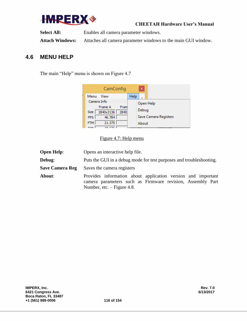
CHEETAH Hardware User’s Manual
IMPERX, Inc. Rev. 7.0 6421 Congress Ave. 6/13/2017 Boca Raton, FL 33487 +1 (561) 989-0006 116 of 154
Select All: Enables all camera parameter windows.
Attach Windows: Attaches all camera parameter windows to the main GUI window.
4.6 MENU HELP
The main “Help” menu is shown on Figure 4.7
Figure 4.7: Help menu
Open Help: Opens an interactive help file.
Debug: Puts the GUI in a debug mode for test purposes and troubleshooting.
Save Camera Reg Saves the camera registers
About: Provides information about application version and important
camera parameters such as Firmware revision, Assembly Part
Number, etc. – Figure 4.8.
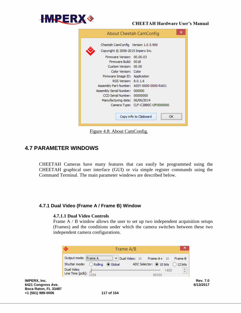
CHEETAH Hardware User’s Manual
IMPERX, Inc. Rev. 7.0 6421 Congress Ave. 6/13/2017 Boca Raton, FL 33487 +1 (561) 989-0006 117 of 154
Figure 4.8: About CamConfig.
4.7 PARAMETER WINDOWS
CHEETAH Cameras have many features that can easily be programmed using the
CHEETAH graphical user interface (GUI) or via simple register commands using the
Command Terminal. The main parameter windows are described below.
4.7.1 Dual Video (Frame A / Frame B) Window
4.7.1.1 Dual Video Controls
Frame A / B window allows the user to set up two independent acquisition setups
(Frames) and the conditions under which the camera switches between these two
independent camera configurations.
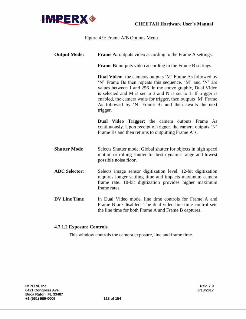
CHEETAH Hardware User’s Manual
IMPERX, Inc. Rev. 7.0 6421 Congress Ave. 6/13/2017 Boca Raton, FL 33487 +1 (561) 989-0006 118 of 154
Figure 4.9: Frame A/B Options Menu
Output Mode: Frame A: outputs video according to the Frame A settings.
Frame B: outputs video according to the Frame B settings.
Dual Video: the cameras outputs ‘M’ Frame As followed by
‘N’ Frame Bs then repeats this sequence. ‘M’ and ‘N’ are
values between 1 and 256. In the above graphic, Dual Video
is selected and M is set to 3 and N is set to 1. If trigger is
enabled, the camera waits for trigger, then outputs ‘M’ Frame
As followed by ‘N’ Frame Bs and then awaits the next
trigger.
Dual Video Trigger: the camera outputs Frame As
continuously. Upon receipt of trigger, the camera outputs ‘N’
Frame Bs and then returns to outputting Frame A’s.
Shutter Mode Selects Shutter mode. Global shutter for objects in high speed
motion or rolling shutter for best dynamic range and lowest
possible noise floor.
ADC Selector: Selects image sensor digitization level. 12-bit digitization
requires longer settling time and impacts maximum camera
frame rate. 10-bit digitization provides higher maximum
frame rates.
DV Line Time In Dual Video mode, line time controls for Frame A and
Frame B are disabled. The dual video line time control sets
the line time for both Frame A and Frame B captures.
4.7.1.2 Exposure Controls
This window controls the camera exposure, line and frame time.
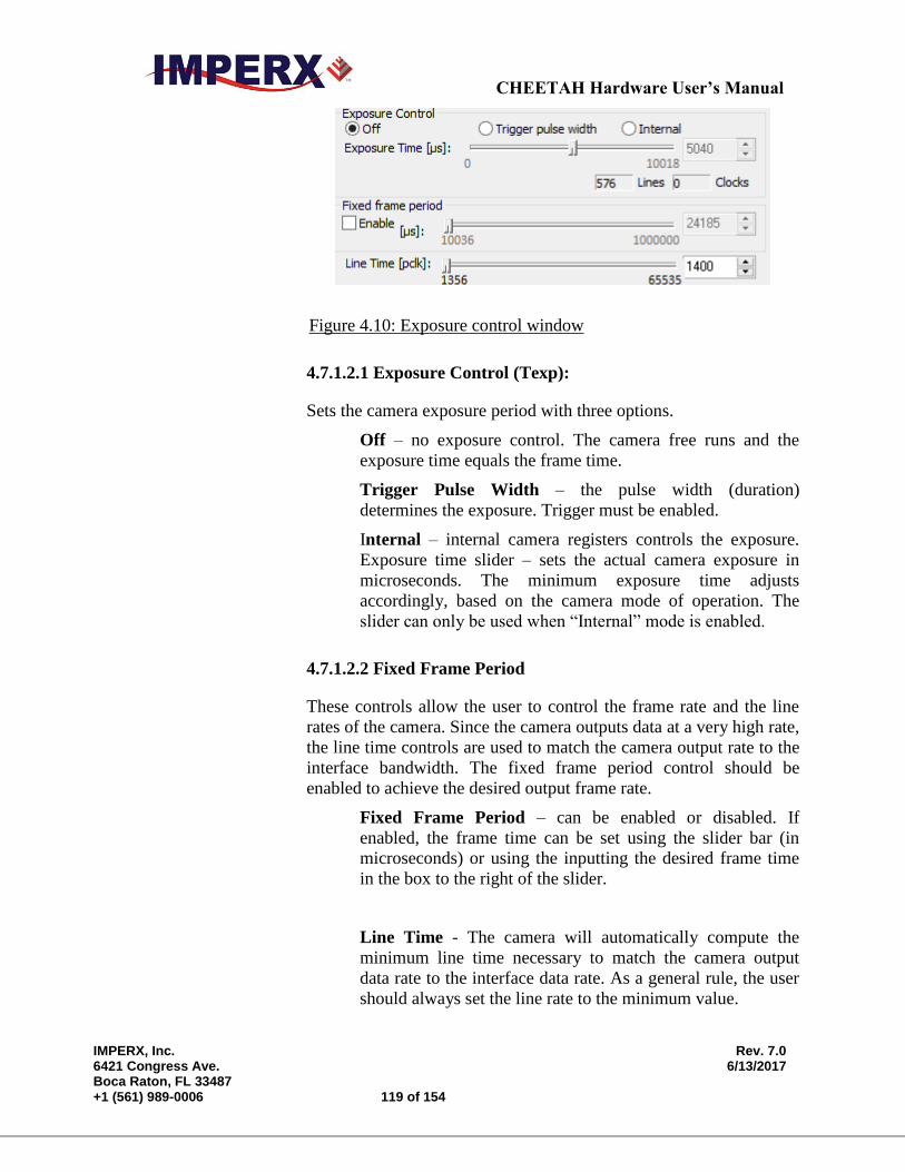
CHEETAH Hardware User’s Manual
IMPERX, Inc. Rev. 7.0 6421 Congress Ave. 6/13/2017 Boca Raton, FL 33487 +1 (561) 989-0006 119 of 154
Figure 4.10: Exposure control window
4.7.1.2.1 Exposure Control (Texp):
Sets the camera exposure period with three options.
Off – no exposure control. The camera free runs and the
exposure time equals the frame time.
Trigger Pulse Width – the pulse width (duration)
determines the exposure. Trigger must be enabled.
Internal – internal camera registers controls the exposure.
Exposure time slider – sets the actual camera exposure in
microseconds. The minimum exposure time adjusts
accordingly, based on the camera mode of operation. The
slider can only be used when “Internal” mode is enabled.
4.7.1.2.2 Fixed Frame Period
These controls allow the user to control the frame rate and the line
rates of the camera. Since the camera outputs data at a very high rate,
the line time controls are used to match the camera output rate to the
interface bandwidth. The fixed frame period control should be
enabled to achieve the desired output frame rate.
Fixed Frame Period – can be enabled or disabled. If
enabled, the frame time can be set using the slider bar (in
microseconds) or using the inputting the desired frame time
in the box to the right of the slider.
Line Time - The camera will automatically compute the
minimum line time necessary to match the camera output
data rate to the interface data rate. As a general rule, the user
should always set the line rate to the minimum value.

CHEETAH Hardware User’s Manual
IMPERX, Inc. Rev. 7.0 6421 Congress Ave. 6/13/2017 Boca Raton, FL 33487 +1 (561) 989-0006 120 of 154
4.7.1.3 Area of Interest (AOI)
AOI is used to select the area of the image sensor which will be output to
the user. The user chose to output the entire image sensor field of view or
any region within this field of view.
Figure 4.11: AOI Functions
Full Frame: This is a pre-programmed AOI providing the full
resolution of the camera.
QFHD: This is a pre-programmed AOI providing a Quad Full HD
(3840 x 2160) centered within the field of view available only on
the C4030 version
Custom: The user can enter the desired area of interest by setting the
active window size (Width, Height) and offset (X, Y). Image
location (1, 1) is top left corner. The user can set the desired window
size by inputting the numbers directly or use the scroll controls.
Horizontal offset value should be multiple of 8, horizontal offset
value should be multiple of 2
4.7.1.4 Subsampling and Averaging
Subsampling and Averaging functions are active within the defined AOI and
is used to reduce the output resolution while maintaining the desired field of
view. See Figure 4.12.
Figure 4.12: Subsampling Functions
Off: Both subsampling and averaging are disabled.
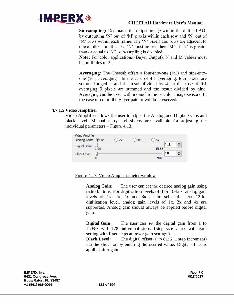
CHEETAH Hardware User’s Manual
IMPERX, Inc. Rev. 7.0 6421 Congress Ave. 6/13/2017 Boca Raton, FL 33487 +1 (561) 989-0006 121 of 154
Subsampling: Decimates the output image within the defined AOI
by outputting ‘N’ out of ‘M’ pixels within each row and ‘N’ out of
‘M’ rows within each frame. The ‘N’ pixels and rows are adjacent to
one another. In all cases, ‘N’ must be less then ‘M’. If ‘N’ is greater
than or equal to ‘M’, subsampling is disabled.
Note: For color applications (Bayer Output), N and M values must
be multiples of 2.
Averaging: The Cheetah offers a four-into-one (4:1) and nine-into-
one (9:1) averaging. In the case of 4:1 averaging, four pixels are
summed together and the result divided by 4. In the case of 9:1
averaging 9 pixels are summed and the result divided by nine.
Averaging can be used with monochrome or color image sensors. In
the case of color, the Bayer pattern will be preserved.
4.7.1.5 Video Amplifier
Video Amplifier allows the user to adjust the Analog and Digital Gains and
black level. Manual entry and sliders are available for adjusting the
individual parameters – Figure 4.13.
Figure 4.13: Video Amp parameter window
Analog Gain: The user can set the desired analog gain using
radio buttons. For digitization levels of 8 or 10-bits, analog gain
levels of 1x, 2x, 4x and 8x.can be selected. For 12-bit
digitization level, analog gain levels of 1x, 2x and 4x are
supported. Analog gain should always be applied before digital
gain.
Digital Gain: The user can set the digital gain from 1 to
15.88x with 128 individual steps. (Step size varies with gain
setting with finer steps at lower gain settings)
Black Level: The digital offset (0 to 8192, 1 step increment)
via the slider or by entering the desired value. Digital offset is
applied after gain.
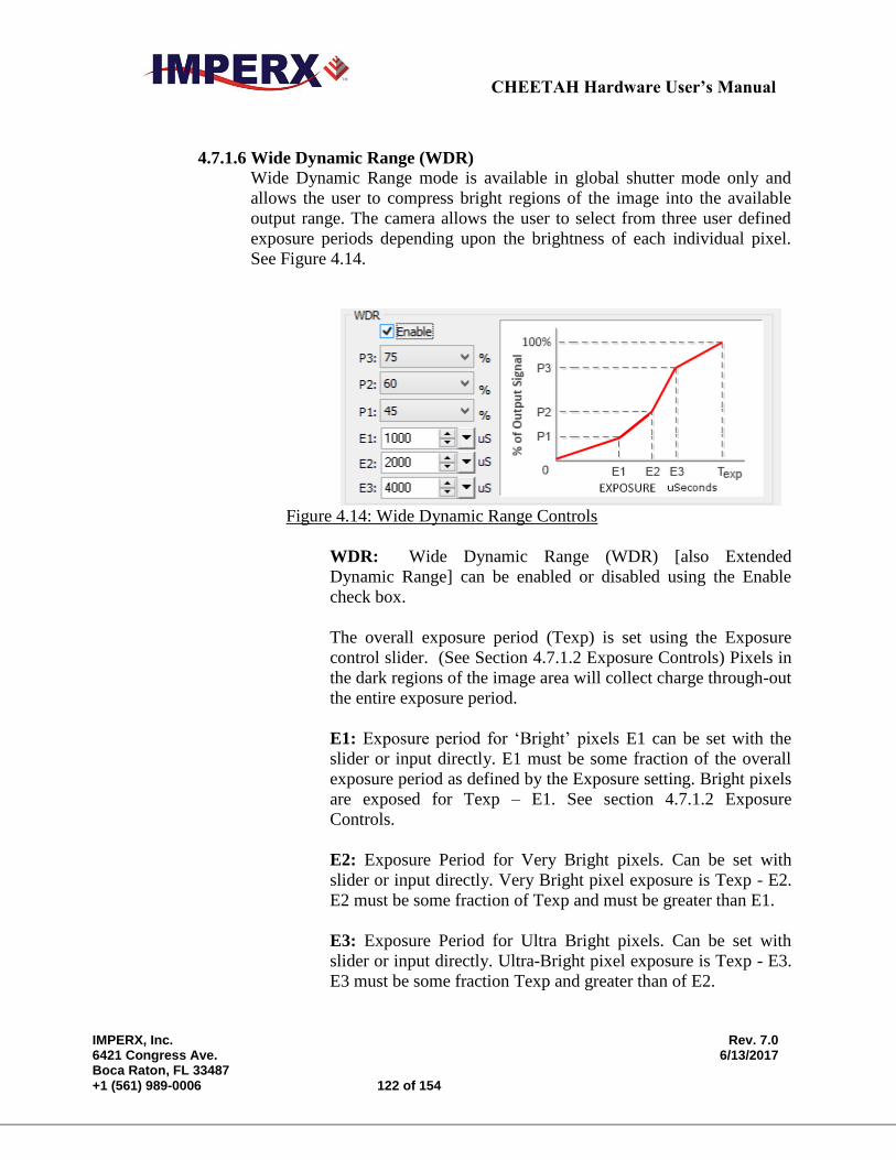
CHEETAH Hardware User’s Manual
IMPERX, Inc. Rev. 7.0 6421 Congress Ave. 6/13/2017 Boca Raton, FL 33487 +1 (561) 989-0006 122 of 154
4.7.1.6 Wide Dynamic Range (WDR)
Wide Dynamic Range mode is available in global shutter mode only and
allows the user to compress bright regions of the image into the available
output range. The camera allows the user to select from three user defined
exposure periods depending upon the brightness of each individual pixel.
See Figure 4.14.
Figure 4.14: Wide Dynamic Range Controls
WDR: Wide Dynamic Range (WDR) [also Extended
Dynamic Range] can be enabled or disabled using the Enable
check box.
The overall exposure period (Texp) is set using the Exposure
control slider. (See Section 4.7.1.2 Exposure Controls) Pixels in
the dark regions of the image area will collect charge through-out
the entire exposure period.
E1: Exposure period for ‘Bright’ pixels E1 can be set with the
slider or input directly. E1 must be some fraction of the overall
exposure period as defined by the Exposure setting. Bright pixels
are exposed for Texp – E1. See section 4.7.1.2 Exposure
Controls.
E2: Exposure Period for Very Bright pixels. Can be set with
slider or input directly. Very Bright pixel exposure is Texp - E2.
E2 must be some fraction of Texp and must be greater than E1.
E3: Exposure Period for Ultra Bright pixels. Can be set with
slider or input directly. Ultra-Bright pixel exposure is Texp - E3.
E3 must be some fraction Texp and greater than of E2.
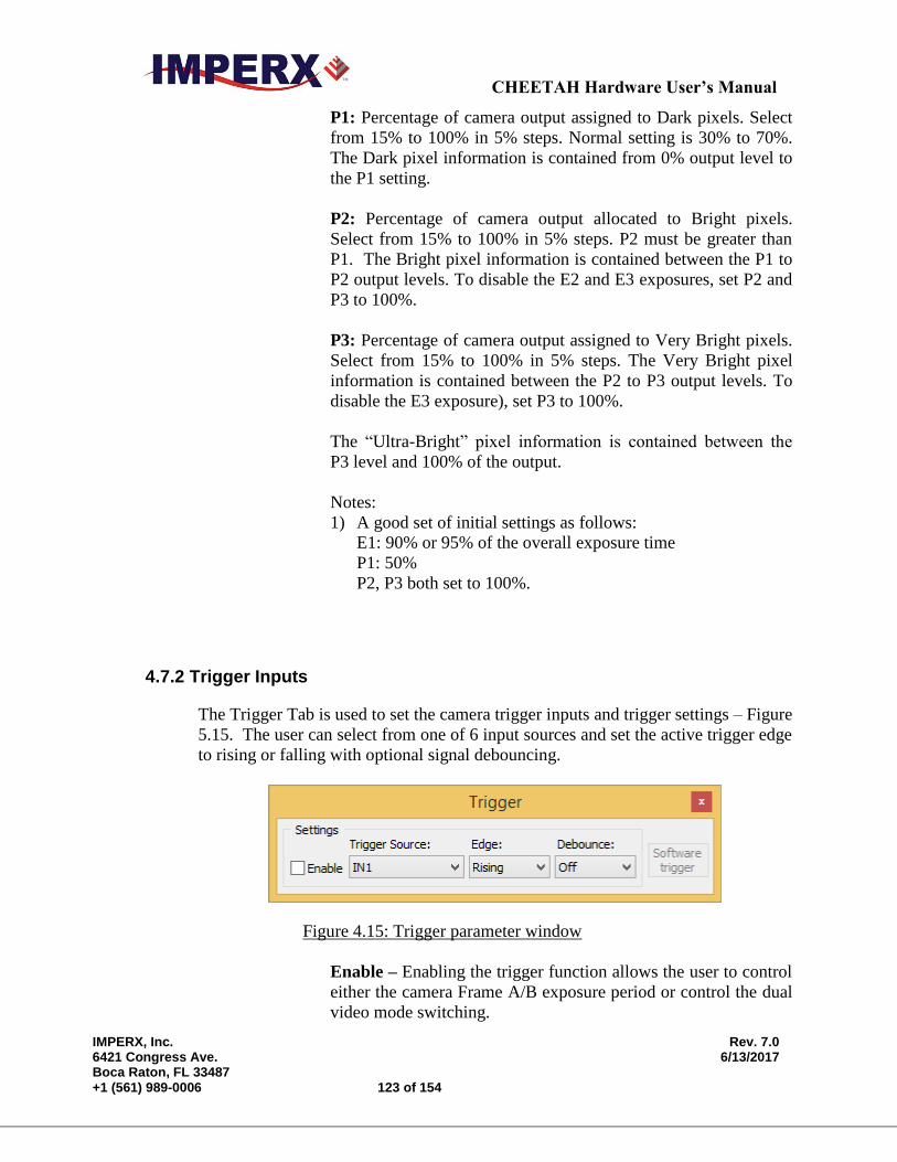
CHEETAH Hardware User’s Manual
IMPERX, Inc. Rev. 7.0 6421 Congress Ave. 6/13/2017 Boca Raton, FL 33487 +1 (561) 989-0006 123 of 154
P1: Percentage of camera output assigned to Dark pixels. Select
from 15% to 100% in 5% steps. Normal setting is 30% to 70%.
The Dark pixel information is contained from 0% output level to
the P1 setting.
P2: Percentage of camera output allocated to Bright pixels.
Select from 15% to 100% in 5% steps. P2 must be greater than
P1. The Bright pixel information is contained between the P1 to
P2 output levels. To disable the E2 and E3 exposures, set P2 and
P3 to 100%.
P3: Percentage of camera output assigned to Very Bright pixels.
Select from 15% to 100% in 5% steps. The Very Bright pixel
information is contained between the P2 to P3 output levels. To
disable the E3 exposure), set P3 to 100%.
The “Ultra-Bright” pixel information is contained between the
P3 level and 100% of the output.
Notes:
1) A good set of initial settings as follows:
E1: 90% or 95% of the overall exposure time
P1: 50%
P2, P3 both set to 100%.
4.7.2 Trigger Inputs
The Trigger Tab is used to set the camera trigger inputs and trigger settings – Figure
5.15. The user can select from one of 6 input sources and set the active trigger edge
to rising or falling with optional signal debouncing.
Figure 4.15: Trigger parameter window
Enable – Enabling the trigger function allows the user to control
either the camera Frame A/B exposure period or control the dual
video mode switching.
CHEETAH Hardware User’s Manual
IMPERX, Inc. Rev. 7.0 6421 Congress Ave. 6/13/2017 Boca Raton, FL 33487 +1 (561) 989-0006 124 of 154
Trigger Source – selects the active triggering input signal from
one of six sources.
In1 –External Camera Input 1
In2 – External Camera Input 2
CC1 – Camera Link Control 1
CC2 – Camera Link Control 2
Software – Software trigger button command that can be
sent by “Software trigger” button.
Pulse Gen – the internal pulse generator produces the trigger
signal.
Edge – the user can select the active triggering edge:
Rising – the rising edge is used for triggering.
Falling – the falling edge is used for triggering.
Debounce – the trigger inputs are de-bounced to prevent
multiple triggering from ringing triggering pulses. The user has
eight choices of de-bounce interval:
Off – No de-bounce
10.0 us – 10 microseconds de-bounce interval.
50.0 us – 50 microseconds de-bounce interval.
100.0 us – 100 microseconds de-bounce interval (default).
500.0 us – 500 microseconds de-bounce interval.
1.0 ms – 1 milliseconds de-bounce interval.
5.0 ms – 5 milliseconds de-bounce interval.
10.0 ms – 10 milliseconds de-bounce interval.
Software Trigger – this button only becomes active when the
Trigger source selected is ‘Software’. Pressing the Software
Trigger button triggers the camera one-time. This can be useful
in debugging operation.
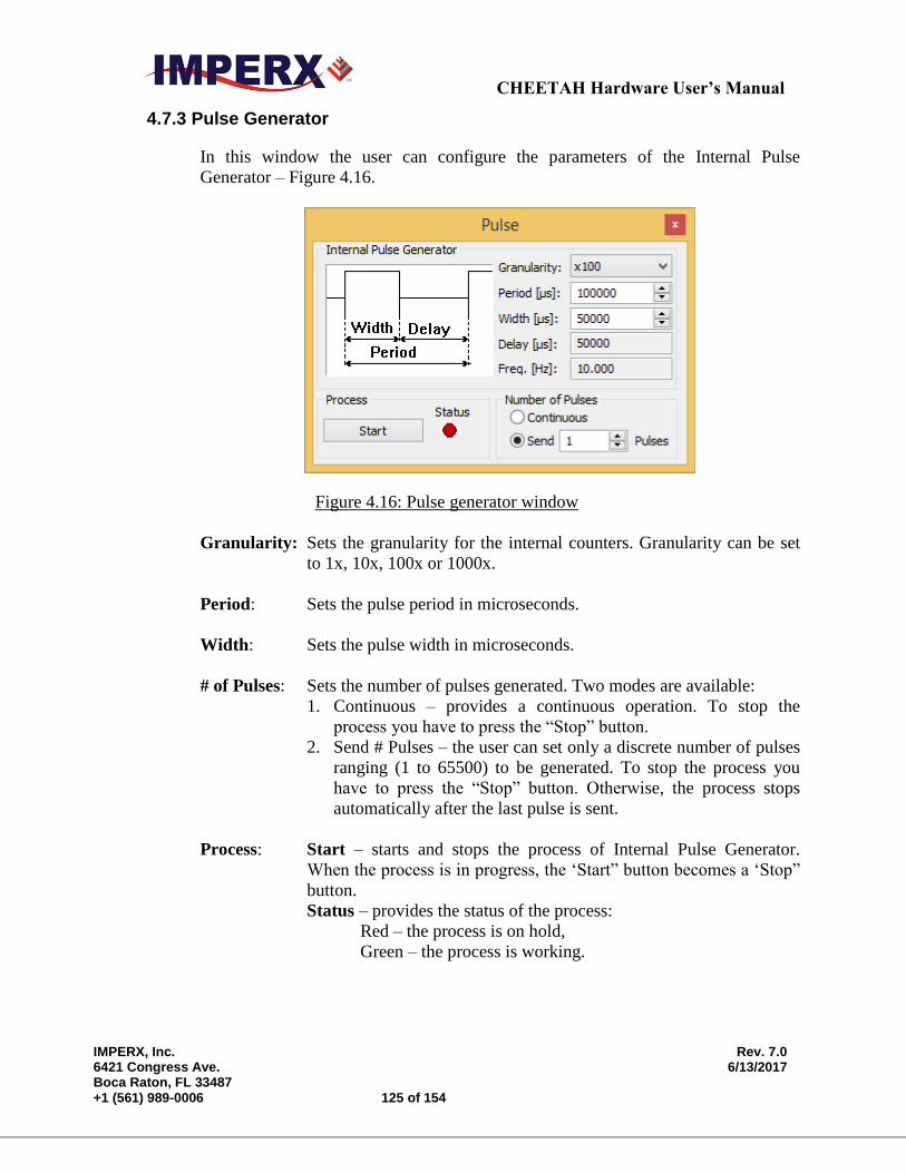
CHEETAH Hardware User’s Manual
IMPERX, Inc. Rev. 7.0 6421 Congress Ave. 6/13/2017 Boca Raton, FL 33487 +1 (561) 989-0006 125 of 154
4.7.3 Pulse Generator
In this window the user can configure the parameters of the Internal Pulse
Generator – Figure 4.16.
Figure 4.16: Pulse generator window
Granularity: Sets the granularity for the internal counters. Granularity can be set
to 1x, 10x, 100x or 1000x.
Period: Sets the pulse period in microseconds.
Width: Sets the pulse width in microseconds.
# of Pulses: Sets the number of pulses generated. Two modes are available:
1. Continuous – provides a continuous operation. To stop the
process you have to press the “Stop” button.
2. Send # Pulses – the user can set only a discrete number of pulses
ranging (1 to 65500) to be generated. To stop the process you
have to press the “Stop” button. Otherwise, the process stops
automatically after the last pulse is sent.
Process: Start – starts and stops the process of Internal Pulse Generator.
When the process is in progress, the ‘Start” button becomes a ‘Stop”
button.
Status – provides the status of the process:
Red – the process is on hold,
Green – the process is working.
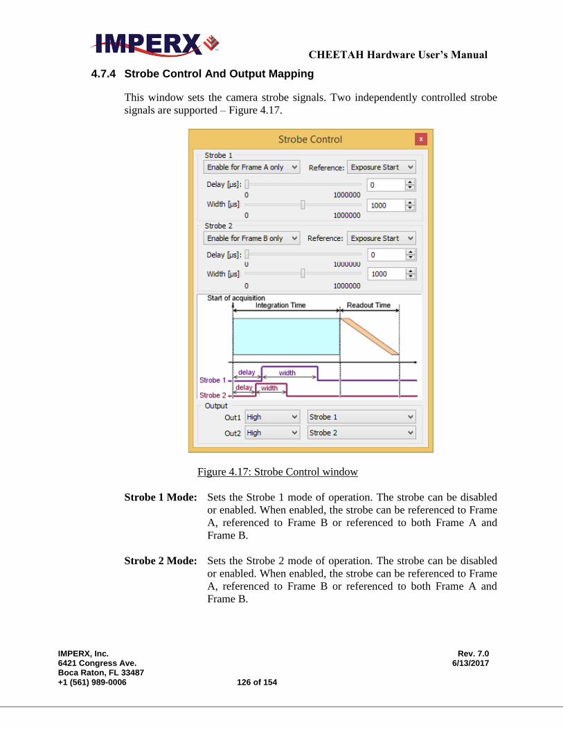
CHEETAH Hardware User’s Manual
IMPERX, Inc. Rev. 7.0 6421 Congress Ave. 6/13/2017 Boca Raton, FL 33487 +1 (561) 989-0006 126 of 154
4.7.4 Strobe Control And Output Mapping
This window sets the camera strobe signals. Two independently controlled strobe
signals are supported – Figure 4.17.
Figure 4.17: Strobe Control window
Strobe 1 Mode: Sets the Strobe 1 mode of operation. The strobe can be disabled
or enabled. When enabled, the strobe can be referenced to Frame
A, referenced to Frame B or referenced to both Frame A and
Frame B.
Strobe 2 Mode: Sets the Strobe 2 mode of operation. The strobe can be disabled
or enabled. When enabled, the strobe can be referenced to Frame
A, referenced to Frame B or referenced to both Frame A and
Frame B.
CHEETAH Hardware User’s Manual
IMPERX, Inc. Rev. 7.0 6421 Congress Ave. 6/13/2017 Boca Raton, FL 33487 +1 (561) 989-0006 127 of 154
Reference: Sets the reference for the Strobe pulse. Options are either the
beginning of the Frame “X” exposure period or the beginning of
the Frame “X” readout period.
Delay/Width: Sets the duration and delay of the strobe sent to the camera
output. The user can set the strobe pulse width and the delay
from 0 to 1,000,000 us.
OUTPUT MAPPING
Out1 External Output 1 can be mapped to the following:
No Mapping, Trigger Input (Mirror), Pulse Generator, Strobe 1
or Strobe 2
Out1 Polarity: External Output 1 polarity can be changed to be active High or
Low.
Out2 External Output 2 can be mapped to the following:
No Mapping, Trigger Input (Mirror), Pulse Generator, Strobe 1
or Strobe 2
Out2 Polarity: External Output 2 polarity can be changed to be active High or
Low.
4.7.5 Data Output
Data Output window provides full control of the camera digital data output – Figure
4.18.

CHEETAH Hardware User’s Manual
IMPERX, Inc. Rev. 7.0 6421 Congress Ave. 6/13/2017 Boca Raton, FL 33487 +1 (561) 989-0006 128 of 154
Figure 4.18: Data output window
Camera Link Settings: Sets the data format and camera speed. Refer to
Chapter 2 for more information.
Taps – sets the number of image taps used in the current
configuration. These are Camera Link Output Taps. In some
camera the tap selection is not available:
A: 1-Taps: Camera Link (CL) Base mode. Single – only one
CL tap is used. (24-bits)
B: 2-Taps: Camera Link Base (24-bits)
C: 4-Taps: Camera Link (48-bits)
D: 8-Taps: Camera Link Full (72-bits)
E: 10-Taps: Camera Link Deca (80-bits)
Depth – sets the output data bit depth, i.e. the number of output
bits per pixel and mapped to the camera link output. Options are
8, 10 or 12 bits.
LUT Settings: Enable: enables the usage of the selected Look-Up Table
(LUT).
LUT Select – selects which of the two supported LUTs will
be used. By default LUT #1 is factory programmed with standard
Gamma of 0.45. LUT #1 and LUT #2 can be reprogrammed by
the user.
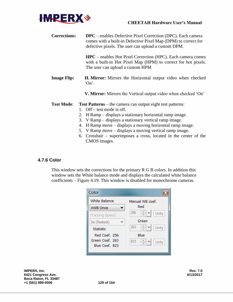
CHEETAH Hardware User’s Manual
IMPERX, Inc. Rev. 7.0 6421 Congress Ave. 6/13/2017 Boca Raton, FL 33487 +1 (561) 989-0006 129 of 154
Corrections: DPC – enables Defective Pixel Correction (DPC). Each camera
comes with a built-in Defective Pixel Map (DPM) to correct for
defective pixels. The user can upload a custom DPM.
HPC – enables Hot Pixel Correction (HPC). Each camera comes
with a built-in Hot Pixel Map (HPM) to correct for hot pixels.
The user can upload a custom HPM
Image Flip: H. Mirror: Mirrors the Horizontal output video when checked
‘On’.
V. Mirror: Mirrors the Vertical output video when checked ‘On’
Test Mode: Test Patterns – the camera can output eight test patterns:
1. Off – test mode is off.
2. H Ramp – displays a stationary horizontal ramp image.
3. V Ramp – displays a stationary vertical ramp image.
4. H Ramp move – displays a moving horizontal ramp image.
5. V Ramp move – displays a moving vertical ramp image.
6. Crosshair – superimposes a cross, located in the center of the
CMOS images.
4.7.6 Color
This window sets the corrections for the primary R G B colors. In addition this
window sets the White balance mode and displays the calculated white balance
coefficients – Figure 4.19. This window is disabled for monochrome cameras.

CHEETAH Hardware User’s Manual
IMPERX, Inc. Rev. 7.0 6421 Congress Ave. 6/13/2017 Boca Raton, FL 33487 +1 (561) 989-0006 130 of 154
Figure 4.19: Color window
White Balance: Sets the White balance mode of operation.
1. “Off” – No white balance is performed.
2. “AWB Once” – the camera analyzes only one image frame,
calculates only one set correction coefficients, and all
subsequent frames are corrected with this set of coefficients.
3. “AWB Tracking” – the camera analyzes every frame, a set of
correction coefficients are derived for each frame and applied
to the next frame.
4. “Manual” – the camera uses the correction coefficients as
entered from the user.
Manual WBC: The user enters manually the white balance coefficients for each
color. The range is from 0 to 255 (255 is equal to 1.0x). The user
has option to set all coefficients to “Zero”.
Tracking Speed: For Auto-White Balance (AWB), the user has the option of
selecting from five update rates. When 1x is selected, the AWB
algorithm responds slowly to any changes in the scene
illumination whereas 5x tracking provides most responsiveness.
Manual WB: The user can set individually the desired digital gain for each
primary color R G B (1.0x to 4.0x, 0.001x increment) via the
arrows or by entering the desired value. The user has option to
set all gains to “Unity” (1.0x)

CHEETAH Hardware User’s Manual
IMPERX, Inc. Rev. 7.0 6421 Congress Ave. 6/13/2017 Boca Raton, FL 33487 +1 (561) 989-0006 131 of 154
CHAPTER 5 Cheetah Warranty and Support
Cheetah Warranty and Support
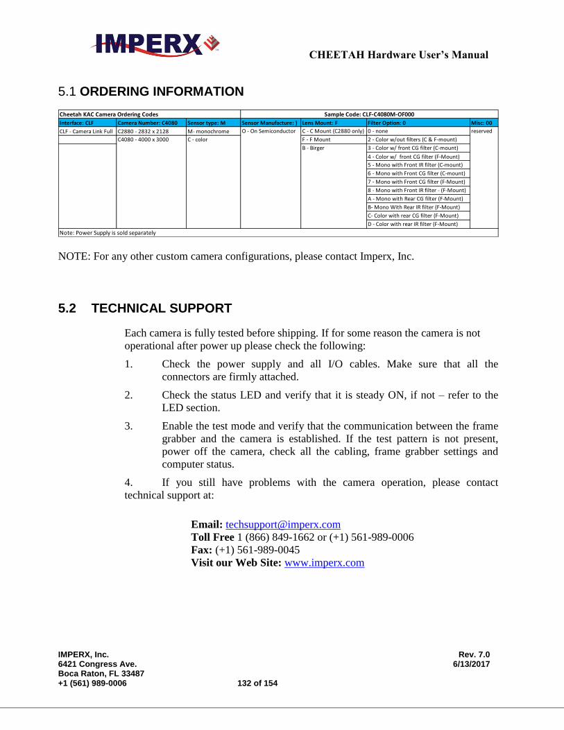
CHEETAH Hardware User’s Manual
IMPERX, Inc. Rev. 7.0 6421 Congress Ave. 6/13/2017 Boca Raton, FL 33487 +1 (561) 989-0006 132 of 154
5.1 ORDERING INFORMATION
Interface: CLF Camera Number: C4080 Sensor type: M Sensor Manufacture: ) Lens Mount: F Filter Option: 0 Misc: 00
CLF - Camera Link Full C2880 - 2832 x 2128 M- monochrome C - C Mount (C2880 only) 0 - none
F - F Mount 2 - Color w/out filters (C & F-mount)
3 - Color w/ front CG filter (C-mount)
4 - Color w/ front CG filter (F-Mount)
5 - Mono with Front IR filter (C-mount)
6 - Mono with Front CG filter (C-mount)
7 - Mono with Front CG filter (F-Mount)
8 - Mono with Front IR filter - (F-Mount)
A - Mono with Rear CG filter (F-Mount)
B- Mono With Rear IR filter (F-Mount)
C- Color with rear CG filter (F-Mount)
D - Color with rear IR filter (F-Mount)
Note: Power Supply is sold separately
Cheetah KAC Camera Ordering Codes Sample Code: CLF-C4080M-OF000
B - Birger
C4080 - 4000 x 3000 C - color
O - On Semiconductor reserved
NOTE: For any other custom camera configurations, please contact Imperx, Inc.
5.2 TECHNICAL SUPPORT
Each camera is fully tested before shipping. If for some reason the camera is not
operational after power up please check the following:
1. Check the power supply and all I/O cables. Make sure that all the
connectors are firmly attached.
2. Check the status LED and verify that it is steady ON, if not – refer to the
LED section.
3. Enable the test mode and verify that the communication between the frame
grabber and the camera is established. If the test pattern is not present,
power off the camera, check all the cabling, frame grabber settings and
computer status.
4. If you still have problems with the camera operation, please contact
technical support at:
Email: [email protected]
Toll Free 1 (866) 849-1662 or (+1) 561-989-0006
Fax: (+1) 561-989-0045
Visit our Web Site: www.imperx.com
CHEETAH Hardware User’s Manual
IMPERX, Inc. Rev. 7.0 6421 Congress Ave. 6/13/2017 Boca Raton, FL 33487 +1 (561) 989-0006 133 of 154
5.3 WARRANTY
Imperx warrants performance of its products and related software to the
specifications applicable at the time of sale in accordance with Imperx’s
standard warranty, which is 2 (two) years parts and labor. FOR GLASSLESS
CAMERAS THE CMOS IS NOT COVERED BY THE WARRANTY.
Do not open the housing of the camera. Warranty voids if the housing has
been open or tampered.
IMPORTANT NOTICE
This camera has been tested and complies with the limits of Class A digital
device, pursuant to part 15 of the FCC rules.
Copyright © 2013 Imperx Inc. All rights reserved. All information provided
in this manual is believed to be accurate and reliable. No responsibility is
assumed by Imperx for its use. Imperx reserves the right to make changes to
this information without notice. Redistribution of this manual in whole or in
part, by any means, is prohibited without obtaining prior permission from
Imperx. Imperx reserves the right to make changes to its products or to
discontinue any product or service without notice, and advises its customers to
obtain the latest version of relevant information to verify, before placing
orders, that the information being relied on is current.
IMPERX PRODUCTS ARE NOT DESIGNED, INTENDED,
AUTHORIZED, OR WARRANTED TO BE SUITABLE FOR USE IN
LIFE-SUPPORT APPLICATIONS, DEVICES OR SYSTEMS OR
OTHER CRITICAL APPLICATIONS, WHERE MALFUNCTION OF
THESE PRODUCTS CAN REASONABLY BE EXPECTED TO
RESULT IN PERSONAL INJURY. IMPERX CUSTOMERS USING OR
SELLING THESE PRODUCTS FOR USE IN SUCH APPLICATIONS
DO SO AT THEIR OWN RISK AND AGREE TO FULLY INDEMNIFY
IMPERX FOR ANY DAMAGES RESULTING FROM SUCH
IMPROPER USE OR SALE.
CHEETAH Hardware User’s Manual
IMPERX, Inc. Rev. 7.0 6421 Congress Ave. 6/13/2017 Boca Raton, FL 33487 +1 (561) 989-0006 134 of 154
Appendix A – Camera Configuration Reference
Camera Configuration Reference
This appendix provides a quick reference to the camera configuration
workspace registers.
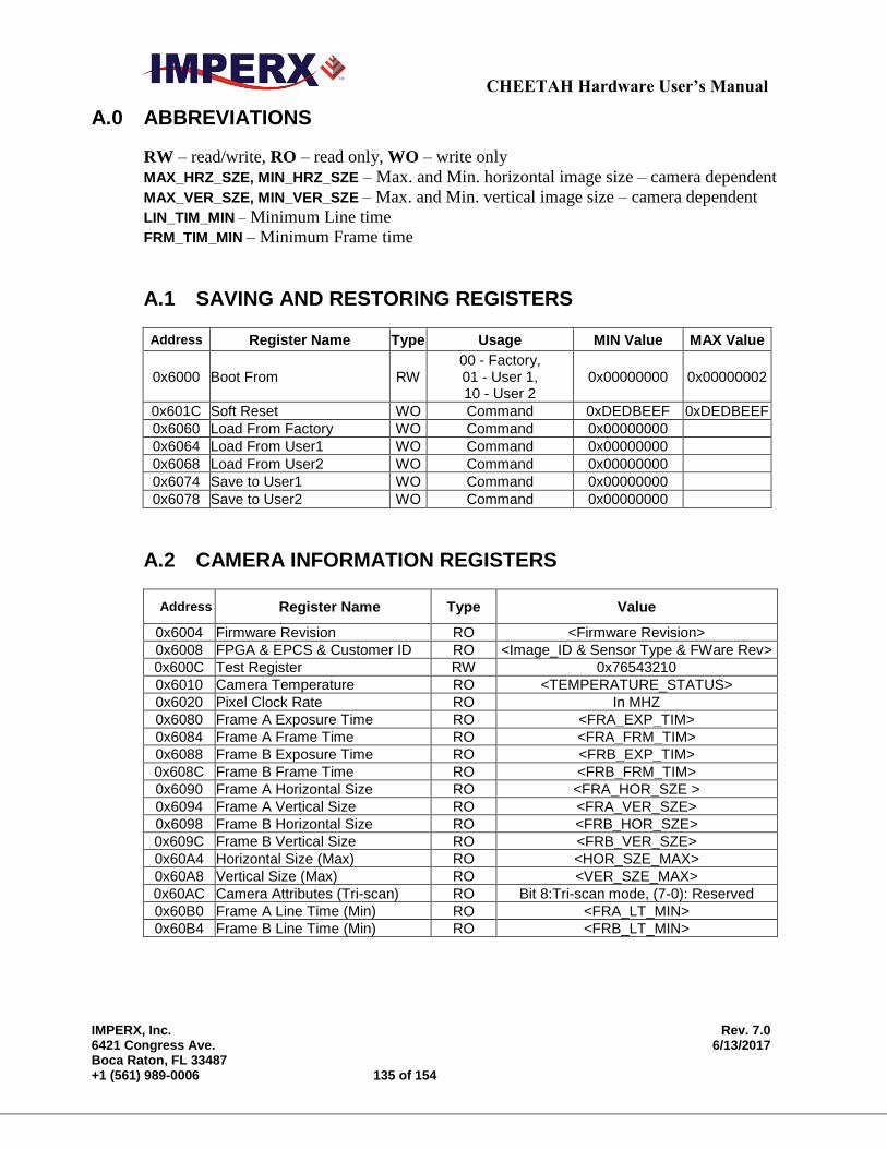
CHEETAH Hardware User’s Manual
IMPERX, Inc. Rev. 7.0 6421 Congress Ave. 6/13/2017 Boca Raton, FL 33487 +1 (561) 989-0006 135 of 154
A.0 ABBREVIATIONS
RW – read/write, RO – read only, WO – write only
MAX_HRZ_SZE, MIN_HRZ_SZE – Max. and Min. horizontal image size – camera dependent
MAX_VER_SZE, MIN_VER_SZE – Max. and Min. vertical image size – camera dependent
LIN_TIM_MIN – Minimum Line time
FRM_TIM_MIN – Minimum Frame time
A.1 SAVING AND RESTORING REGISTERS
Address Register Name Type Usage MIN Value MAX Value
0x6000 Boot From RW 00 - Factory, 01 - User 1, 10 - User 2
0x00000000 0x00000002
0x601C Soft Reset WO Command 0xDEDBEEF 0xDEDBEEF
0x6060 Load From Factory WO Command 0x00000000
0x6064 Load From User1 WO Command 0x00000000
0x6068 Load From User2 WO Command 0x00000000
0x6074 Save to User1 WO Command 0x00000000
0x6078 Save to User2 WO Command 0x00000000
A.2 CAMERA INFORMATION REGISTERS
Address Register Name Type Value
0x6004 Firmware Revision RO <Firmware Revision>
0x6008 FPGA & EPCS & Customer ID RO <Image_ID & Sensor Type & FWare Rev>
0x600C Test Register RW 0x76543210
0x6010 Camera Temperature RO <TEMPERATURE_STATUS>
0x6020 Pixel Clock Rate RO In MHZ
0x6080 Frame A Exposure Time RO <FRA_EXP_TIM>
0x6084 Frame A Frame Time RO <FRA_FRM_TIM>
0x6088 Frame B Exposure Time RO <FRB_EXP_TIM>
0x608C Frame B Frame Time RO <FRB_FRM_TIM>
0x6090 Frame A Horizontal Size RO <FRA_HOR_SZE >
0x6094 Frame A Vertical Size RO <FRA_VER_SZE>
0x6098 Frame B Horizontal Size RO <FRB_HOR_SZE>
0x609C Frame B Vertical Size RO <FRB_VER_SZE>
0x60A4 Horizontal Size (Max) RO <HOR_SZE_MAX>
0x60A8 Vertical Size (Max) RO <VER_SZE_MAX>
0x60AC Camera Attributes (Tri-scan) RO Bit 8:Tri-scan mode, (7-0): Reserved
0x60B0 Frame A Line Time (Min) RO <FRA_LT_MIN>
0x60B4 Frame B Line Time (Min) RO <FRB_LT_MIN>
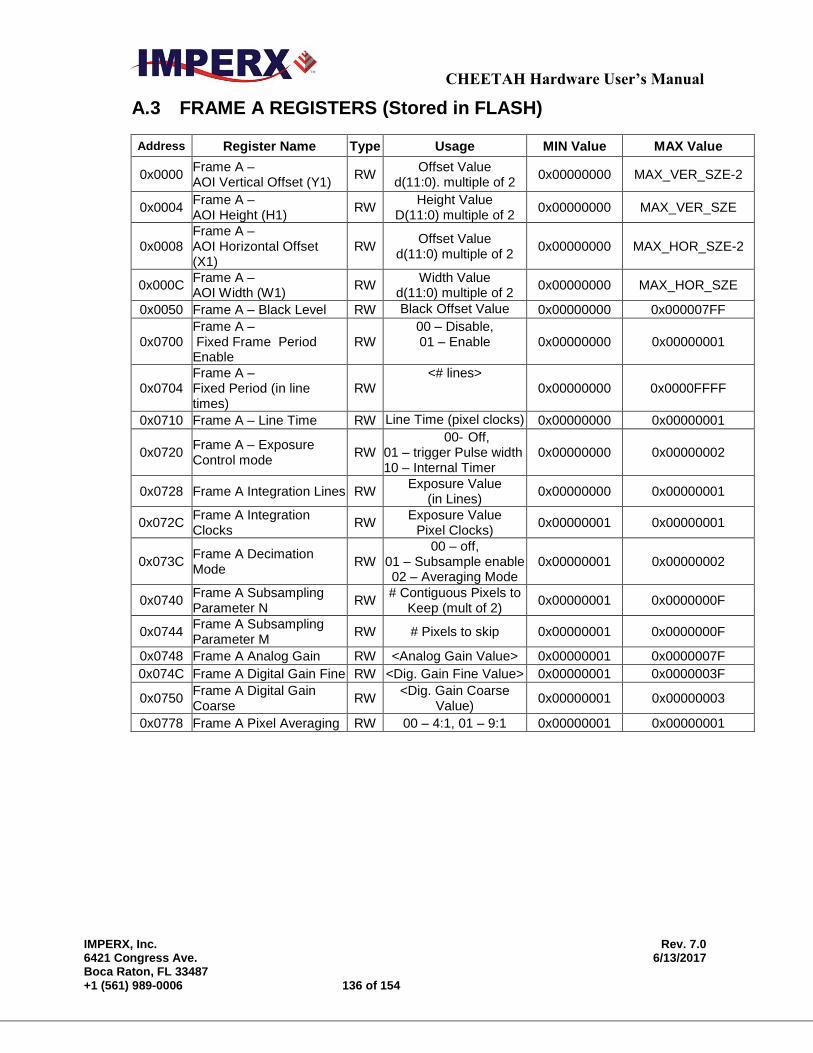
CHEETAH Hardware User’s Manual
IMPERX, Inc. Rev. 7.0 6421 Congress Ave. 6/13/2017 Boca Raton, FL 33487 +1 (561) 989-0006 136 of 154
A.3 FRAME A REGISTERS (Stored in FLASH)
Address Register Name Type Usage MIN Value MAX Value
0x0000 Frame A – AOI Vertical Offset (Y1)
RW Offset Value
d(11:0). multiple of 2 0x00000000 MAX_VER_SZE-2
0x0004 Frame A – AOI Height (H1)
RW Height Value
D(11:0) multiple of 2 0x00000000 MAX_VER_SZE
0x0008 Frame A – AOI Horizontal Offset (X1)
RW Offset Value
d(11:0) multiple of 2 0x00000000 MAX_HOR_SZE-2
0x000C Frame A – AOI Width (W1)
RW Width Value
d(11:0) multiple of 2 0x00000000 MAX_HOR_SZE
0x0050 Frame A – Black Level RW Black Offset Value 0x00000000 0x000007FF
0x0700 Frame A – Fixed Frame Period Enable
RW 00 – Disable, 01 – Enable 0x00000000 0x00000001
0x0704 Frame A – Fixed Period (in line times)
RW <# lines>
0x00000000 0x0000FFFF
0x0710 Frame A – Line Time RW Line Time (pixel clocks) 0x00000000 0x00000001
0x0720 Frame A – Exposure Control mode
RW 00- Off,
01 – trigger Pulse width 10 – Internal Timer
0x00000000 0x00000002
0x0728 Frame A Integration Lines RW Exposure Value
(in Lines) 0x00000000 0x00000001
0x072C Frame A Integration Clocks
RW Exposure Value
Pixel Clocks) 0x00000001 0x00000001
0x073C Frame A Decimation Mode
RW 00 – off,
01 – Subsample enable 02 – Averaging Mode
0x00000001 0x00000002
0x0740 Frame A Subsampling Parameter N
RW # Contiguous Pixels to
Keep (mult of 2) 0x00000001 0x0000000F
0x0744 Frame A Subsampling Parameter M
RW # Pixels to skip 0x00000001 0x0000000F
0x0748 Frame A Analog Gain RW <Analog Gain Value> 0x00000001 0x0000007F
0x074C Frame A Digital Gain Fine RW <Dig. Gain Fine Value> 0x00000001 0x0000003F
0x0750 Frame A Digital Gain Coarse
RW <Dig. Gain Coarse
Value) 0x00000001 0x00000003
0x0778 Frame A Pixel Averaging RW 00 – 4:1, 01 – 9:1 0x00000001 0x00000001

CHEETAH Hardware User’s Manual
IMPERX, Inc. Rev. 7.0 6421 Congress Ave. 6/13/2017 Boca Raton, FL 33487 +1 (561) 989-0006 137 of 154
A.4 FRAME A WDR REGISTERS
Address Register Name Typ
e Usage MIN Value MAX Value
0x0600 Frame A WDR Enable RW 00 – disable 01 –enable
0x00000000 0x00000001
0x0604 Frame A WDR P1 (Dark Pixel Allocation of Output Range)
RW
0000 – 100%, 0001 – 90% 0010 – 80%, 0011 – 75% 0100 – 70%, 0101 – 65% 0110 – 60%, 0111 – 55% 1000 – 50%, 1001 – 45% 1010 – 40%, 1011 – 35% 1100 – 30%, 1101 – 25% 1110 - 20%, 1111 - 15%
0x00000000 0x0000000F
0x0608 Frame A WDR P2 (Bright Pixel Allocation of Output Range)
RW
0000 – 100%, 0001 – 90% 0010 – 80%, 0011 – 75% 0100 – 70%, 0101 – 65% 0110 – 60%, 0111 – 55% 1000 – 50%, 1001 – 45% 1010 – 40%, 1011 – 35% 1100 – 30%, 1101 – 25% 1110 - 20%, 1111 - 15%
0x00000000 0x0000000F
0x060C Frame A WDR P3 (Set to 0000)
RW
0000 – 100%, 0001 – 90% 0010 – 80%, 0011 – 75% 0100 – 70%, 0101 – 65% 0110 – 60%, 0111 – 55% 1000 – 50%, 1001 – 45% 1010 – 40%, 1011 – 35% 1100 – 30%, 1101 – 25% 1110 - 20%, 1111 - 15%
0x00000000 0x0000000F
0x0610 Frame A WDR Bright Pixel Exposure (E1)
RW <Bright Pixel Exposure Time
(us)> 0x00000000 0x000FFFFF
0x0614 Frame A WDR Very-bright Pixel Exposure (E2)
RW <Very-Bright Pixel Exposure
Time (us)> 0x00000000 0x000FFFFF
0x0660 Frame A WDR Ultra-bright Pixel Exposure (E3)
RW <Ultra-Bright Pixel Exposure
Time (us)> 0x00000000 0x000FFFFF
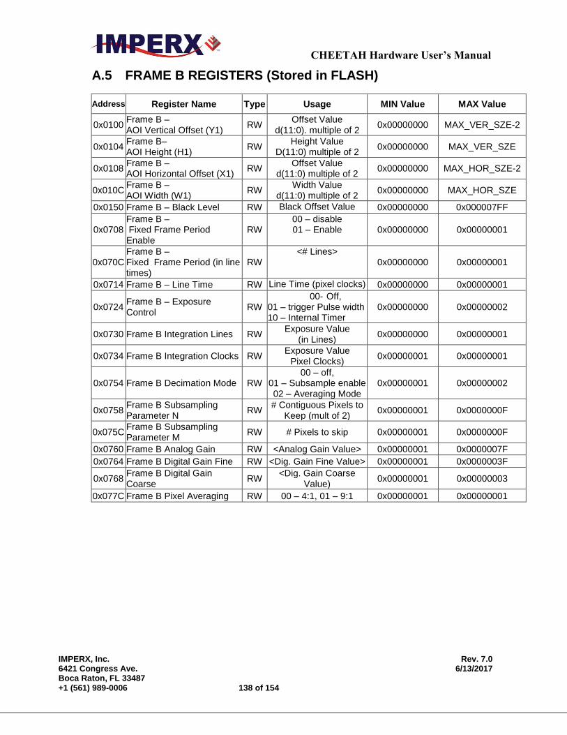
CHEETAH Hardware User’s Manual
IMPERX, Inc. Rev. 7.0 6421 Congress Ave. 6/13/2017 Boca Raton, FL 33487 +1 (561) 989-0006 138 of 154
A.5 FRAME B REGISTERS (Stored in FLASH)
Address Register Name Type Usage MIN Value MAX Value
0x0100 Frame B – AOI Vertical Offset (Y1)
RW Offset Value
d(11:0). multiple of 2 0x00000000 MAX_VER_SZE-2
0x0104 Frame B– AOI Height (H1)
RW Height Value
D(11:0) multiple of 2 0x00000000 MAX_VER_SZE
0x0108 Frame B – AOI Horizontal Offset (X1)
RW Offset Value
d(11:0) multiple of 2 0x00000000 MAX_HOR_SZE-2
0x010C Frame B – AOI Width (W1)
RW Width Value
d(11:0) multiple of 2 0x00000000 MAX_HOR_SZE
0x0150 Frame B – Black Level RW Black Offset Value 0x00000000 0x000007FF
0x0708 Frame B – Fixed Frame Period Enable
RW 00 – disable 01 – Enable 0x00000000 0x00000001
0x070C Frame B – Fixed Frame Period (in line times)
RW <# Lines>
0x00000000 0x00000001
0x0714 Frame B – Line Time RW Line Time (pixel clocks) 0x00000000 0x00000001
0x0724 Frame B – Exposure Control
RW 00- Off,
01 – trigger Pulse width 10 – Internal Timer
0x00000000 0x00000002
0x0730 Frame B Integration Lines RW Exposure Value
(in Lines) 0x00000000 0x00000001
0x0734 Frame B Integration Clocks RW Exposure Value
Pixel Clocks) 0x00000001 0x00000001
0x0754 Frame B Decimation Mode RW 00 – off,
01 – Subsample enable 02 – Averaging Mode
0x00000001 0x00000002
0x0758 Frame B Subsampling Parameter N
RW # Contiguous Pixels to
Keep (mult of 2) 0x00000001 0x0000000F
0x075C Frame B Subsampling Parameter M
RW # Pixels to skip 0x00000001 0x0000000F
0x0760 Frame B Analog Gain RW <Analog Gain Value> 0x00000001 0x0000007F
0x0764 Frame B Digital Gain Fine RW <Dig. Gain Fine Value> 0x00000001 0x0000003F
0x0768 Frame B Digital Gain Coarse
RW <Dig. Gain Coarse
Value) 0x00000001 0x00000003
0x077C Frame B Pixel Averaging RW 00 – 4:1, 01 – 9:1 0x00000001 0x00000001
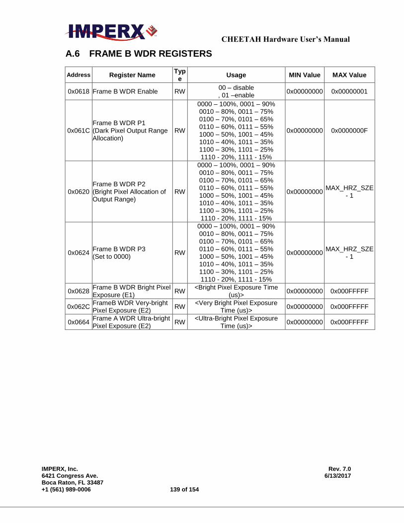
CHEETAH Hardware User’s Manual
IMPERX, Inc. Rev. 7.0 6421 Congress Ave. 6/13/2017 Boca Raton, FL 33487 +1 (561) 989-0006 139 of 154
A.6 FRAME B WDR REGISTERS
Address Register Name Typ
e Usage MIN Value MAX Value
0x0618 Frame B WDR Enable RW 00 – disable , 01 –enable
0x00000000 0x00000001
0x061C Frame B WDR P1 (Dark Pixel Output Range Allocation)
RW
0000 – 100%, 0001 – 90% 0010 – 80%, 0011 – 75% 0100 – 70%, 0101 – 65% 0110 – 60%, 0111 – 55% 1000 – 50%, 1001 – 45% 1010 – 40%, 1011 – 35% 1100 – 30%, 1101 – 25% 1110 - 20%, 1111 - 15%
0x00000000 0x0000000F
0x0620 Frame B WDR P2 (Bright Pixel Allocation of Output Range)
RW
0000 – 100%, 0001 – 90% 0010 – 80%, 0011 – 75% 0100 – 70%, 0101 – 65% 0110 – 60%, 0111 – 55% 1000 – 50%, 1001 – 45% 1010 – 40%, 1011 – 35% 1100 – 30%, 1101 – 25% 1110 - 20%, 1111 - 15%
0x00000000 MAX_HRZ_SZE
- 1
0x0624 Frame B WDR P3 (Set to 0000)
RW
0000 – 100%, 0001 – 90% 0010 – 80%, 0011 – 75% 0100 – 70%, 0101 – 65% 0110 – 60%, 0111 – 55% 1000 – 50%, 1001 – 45% 1010 – 40%, 1011 – 35% 1100 – 30%, 1101 – 25% 1110 - 20%, 1111 - 15%
0x00000000 MAX_HRZ_SZE
- 1
0x0628 Frame B WDR Bright Pixel Exposure (E1)
RW <Bright Pixel Exposure Time
(us)> 0x00000000 0x000FFFFF
0x062C FrameB WDR Very-bright Pixel Exposure (E2)
RW <Very Bright Pixel Exposure
Time (us)> 0x00000000 0x000FFFFF
0x0664 Frame A WDR Ultra-bright Pixel Exposure (E2)
RW <Ultra-Bright Pixel Exposure
Time (us)> 0x00000000 0x000FFFFF
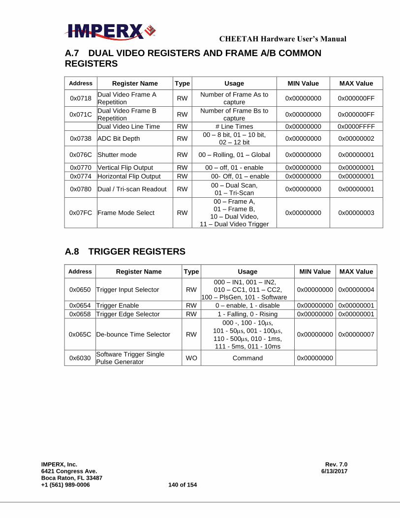
CHEETAH Hardware User’s Manual
IMPERX, Inc. Rev. 7.0 6421 Congress Ave. 6/13/2017 Boca Raton, FL 33487 +1 (561) 989-0006 140 of 154
A.7 DUAL VIDEO REGISTERS AND FRAME A/B COMMON REGISTERS
Address Register Name Type Usage MIN Value MAX Value
0x0718 Dual Video Frame A Repetition
RW Number of Frame As to
capture 0x00000000 0x000000FF
0x071C Dual Video Frame B Repetition
RW Number of Frame Bs to
capture 0x00000000 0x000000FF
Dual Video Line Time RW # Line Times 0x00000000 0x0000FFFF
0x0738 ADC Bit Depth RW 00 – 8 bit, 01 – 10 bit,
02 – 12 bit 0x00000000 0x00000002
0x076C Shutter mode RW 00 – Rolling, 01 – Global 0x00000000 0x00000001
0x0770 Vertical Flip Output RW 00 – off, 01 - enable 0x00000000 0x00000001
0x0774 Horizontal Flip Output RW 00- Off, 01 – enable 0x00000000 0x00000001
0x0780 Dual / Tri-scan Readout RW 00 – Dual Scan,
01 – Tri-Scan 0x00000000 0x00000001
0x07FC Frame Mode Select RW
00 – Frame A, 01 – Frame B,
10 – Dual Video, 11 – Dual Video Trigger
0x00000000 0x00000003
A.8 TRIGGER REGISTERS
Address Register Name Type Usage MIN Value MAX Value
0x0650 Trigger Input Selector RW 000 – IN1, 001 – IN2, 010 – CC1, 011 – CC2, 100 – PlsGen, 101 - Software
0x00000000 0x00000004
0x0654 Trigger Enable RW 0 – enable, 1 - disable 0x00000000 0x00000001
0x0658 Trigger Edge Selector RW 1 - Falling, 0 - Rising 0x00000000 0x00000001
0x065C De-bounce Time Selector RW
000 -, 100 - 10s,
101 - 50s, 001 - 100s,
110 - 500s, 010 - 1ms,
111 - 5ms, 011 - 10ms
0x00000000 0x00000007
0x6030 Software Trigger Single Pulse Generator
WO Command 0x00000000
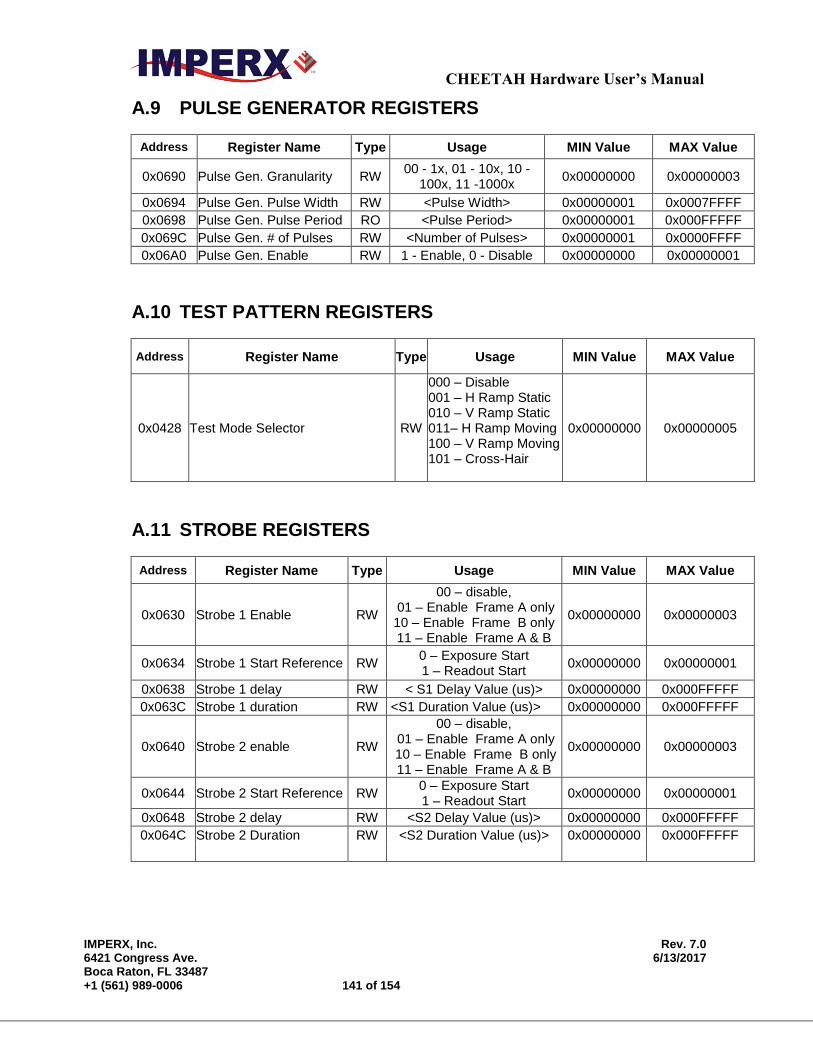
CHEETAH Hardware User’s Manual
IMPERX, Inc. Rev. 7.0 6421 Congress Ave. 6/13/2017 Boca Raton, FL 33487 +1 (561) 989-0006 141 of 154
A.9 PULSE GENERATOR REGISTERS
Address Register Name Type Usage MIN Value MAX Value
0x0690 Pulse Gen. Granularity RW 00 - 1x, 01 - 10x, 10 -
100x, 11 -1000x 0x00000000 0x00000003
0x0694 Pulse Gen. Pulse Width RW <Pulse Width> 0x00000001 0x0007FFFF
0x0698 Pulse Gen. Pulse Period RO <Pulse Period> 0x00000001 0x000FFFFF
0x069C Pulse Gen. # of Pulses RW <Number of Pulses> 0x00000001 0x0000FFFF
0x06A0 Pulse Gen. Enable RW 1 - Enable, 0 - Disable 0x00000000 0x00000001
A.10 TEST PATTERN REGISTERS
Address Register Name Type Usage MIN Value MAX Value
0x0428 Test Mode Selector RW
000 – Disable 001 – H Ramp Static 010 – V Ramp Static 011– H Ramp Moving 100 – V Ramp Moving 101 – Cross-Hair
0x00000000 0x00000005
A.11 STROBE REGISTERS
Address Register Name Type Usage MIN Value MAX Value
0x0630 Strobe 1 Enable RW
00 – disable, 01 – Enable Frame A only 10 – Enable Frame B only 11 – Enable Frame A & B
0x00000000 0x00000003
0x0634 Strobe 1 Start Reference RW 0 – Exposure Start 1 – Readout Start
0x00000000 0x00000001
0x0638 Strobe 1 delay RW < S1 Delay Value (us)> 0x00000000 0x000FFFFF
0x063C Strobe 1 duration RW <S1 Duration Value (us)> 0x00000000 0x000FFFFF
0x0640 Strobe 2 enable RW
00 – disable, 01 – Enable Frame A only 10 – Enable Frame B only 11 – Enable Frame A & B
0x00000000 0x00000003
0x0644 Strobe 2 Start Reference RW 0 – Exposure Start 1 – Readout Start
0x00000000 0x00000001
0x0648 Strobe 2 delay RW <S2 Delay Value (us)> 0x00000000 0x000FFFFF
0x064C Strobe 2 Duration RW <S2 Duration Value (us)> 0x00000000 0x000FFFFF
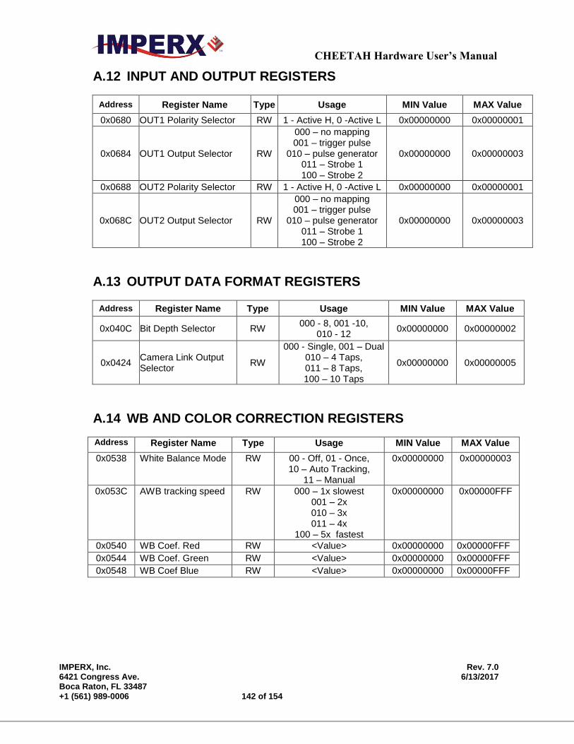
CHEETAH Hardware User’s Manual
IMPERX, Inc. Rev. 7.0 6421 Congress Ave. 6/13/2017 Boca Raton, FL 33487 +1 (561) 989-0006 142 of 154
A.12 INPUT AND OUTPUT REGISTERS
Address Register Name Type Usage MIN Value MAX Value
0x0680 OUT1 Polarity Selector RW 1 - Active H, 0 -Active L 0x00000000 0x00000001
0x0684 OUT1 Output Selector RW
000 – no mapping 001 – trigger pulse
010 – pulse generator 011 – Strobe 1 100 – Strobe 2
0x00000000 0x00000003
0x0688 OUT2 Polarity Selector RW 1 - Active H, 0 -Active L 0x00000000 0x00000001
0x068C OUT2 Output Selector RW
000 – no mapping 001 – trigger pulse
010 – pulse generator 011 – Strobe 1 100 – Strobe 2
0x00000000 0x00000003
A.13 OUTPUT DATA FORMAT REGISTERS
Address Register Name Type Usage MIN Value MAX Value
0x040C Bit Depth Selector RW 000 - 8, 001 -10,
010 - 12 0x00000000 0x00000002
0x0424 Camera Link Output Selector
RW
000 - Single, 001 – Dual 010 – 4 Taps, 011 – 8 Taps, 100 – 10 Taps
0x00000000 0x00000005
A.14 WB AND COLOR CORRECTION REGISTERS
Address Register Name Type Usage MIN Value MAX Value
0x0538 White Balance Mode RW 00 - Off, 01 - Once, 10 – Auto Tracking,
11 – Manual
0x00000000 0x00000003
0x053C AWB tracking speed RW 000 – 1x slowest 001 – 2x 010 – 3x 011 – 4x
100 – 5x fastest
0x00000000 0x00000FFF
0x0540 WB Coef. Red RW <Value> 0x00000000 0x00000FFF
0x0544 WB Coef. Green RW <Value> 0x00000000 0x00000FFF 0x0548 WB Coef Blue RW <Value> 0x00000000 0x00000FFF
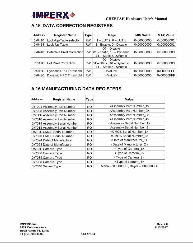
CHEETAH Hardware User’s Manual
IMPERX, Inc. Rev. 7.0 6421 Congress Ave. 6/13/2017 Boca Raton, FL 33487 +1 (561) 989-0006 143 of 154
A.15 DATA CORRECTION REGISTERS
Address Register Name Type Usage MIN Value MAX Value
0x0410 Look-Up-Table selector RW 1 – LUT 2, 0 – LUT 1 0x00000000 0x00000001
0x0414 Look-Up-Table RW 1 - Enable, 0 - Disable 0x00000000 0x00000001
0x0418 Defective Pixel Correction RW 00 – Disable
01 – Static, 10 – Dynamic 11 – Static & Dynamic
0x00000000 0x00000003
0x041C Hot Pixel Correction RW 00 – Disable
01 – Static, 10 – Dynamic, 11 – Static & Dynamic
0x00000000 0x00000003
0x042C Dynamic DPC Threshold RW <Value> 0x00000000 0x00000FFF
0x0430 Dynamic HPC Threshold RW <Value> 0x00000000 0x00000FFF
A.16 MANUFACTURING DATA REGISTERS
Address Register Name Type Value
0x7004 Assembly Part Number RO <Assembly Part Number_1>
0x7008 Assembly Part Number RO <Assembly Part Number_2>
0x700C Assembly Part Number RO <Assembly Part Number_3>
0x7010 Assembly Part Number RO <Assembly Part Number_4>
0x7014 Assembly Serial Number RO <Assembly Serial Number_1>
0x7018 Assembly Serial Number RO Assembly Serial Number_2
0x701C CMOS Serial Number RO <CMOS Serial Number_1>
0x7020 CMOS Serial Number RO <CMOS Serial Number_2>
0x7024 Date of Manufacturer RO <Date of Manufacturer_1>
0x7028 Date of Manufacturer RO <Date of Manufacturer_2>
0x702C Camera Type RO <Type of Camera_1>
0x7030 Camera Type RO <Type of Camera_2>
0x7034 Camera Type RO <Type of Camera_3>
0x7038 Camera Type RO <Type of camera_4>
0x7040 Sensor Type RO Mono – ‘0000000B’, Bayer – ‘0000000C’

CHEETAH Hardware User’s Manual
IMPERX, Inc. Rev. 7.0 6421 Congress Ave. 6/13/2017 Boca Raton, FL 33487 +1 (561) 989-0006 144 of 154
Appendix B – Creating Look Up Tables
Creating Look-Up Tables
This appendix provides a reference on how to create a lookup table using
both an ASCII editor and an Excel spreadsheet.

CHEETAH Hardware User’s Manual
IMPERX, Inc. Rev. 7.0 6421 Congress Ave. 6/13/2017 Boca Raton, FL 33487 +1 (561) 989-0006 145 of 154
B.1 OVERVIEW
The Lookup Table file can be created using any standard ASCII text editor or by
using Microsoft Excel. Additionally, any spreadsheet or mathematical program
capable of generating a comma delimited (.csv) file can be used.
See Appendix E for software load procedure.
B.2 USING AN ASCII TEXT EDITOR
A custom LUT (lookup table) can be prepared using any ASCII text editor, such as
“Notepad” or similar. Alternatively, any spreadsheet program (i.e. Microsoft Excel)
can be used by converting the spreadsheet into a comma delimited (.csv) file. In
either case, the file must be renamed to include the .lut extension. The .lut file has
two main sections: a header and a table. The ‘header’ section is a free text area of
up to 256 ASCII characters. Each line of the header section must be terminated in a
comma. The ‘table’ section of the file contains an array of 4096 lines with each line
containing an input value followed by a comma and an output value. The input
values represent incoming pixels and the output values represent what each
incoming pixel should be converted into as an output pixel.
The format of the .LUT file is as follows:
-- Look Up Table input file example,
-- lines beginning with two dashes are comments,
-- and are ignored by parser,
:Header,
-- this is the text that will get displayed with a 'glh' command,
Function is 'Negative Image',
Created by John Doe,
Date 1/14/09,
:Table,
-- input output,
0,4095
1,4094
2,4093
3,4092
4,4091
:
4095,0
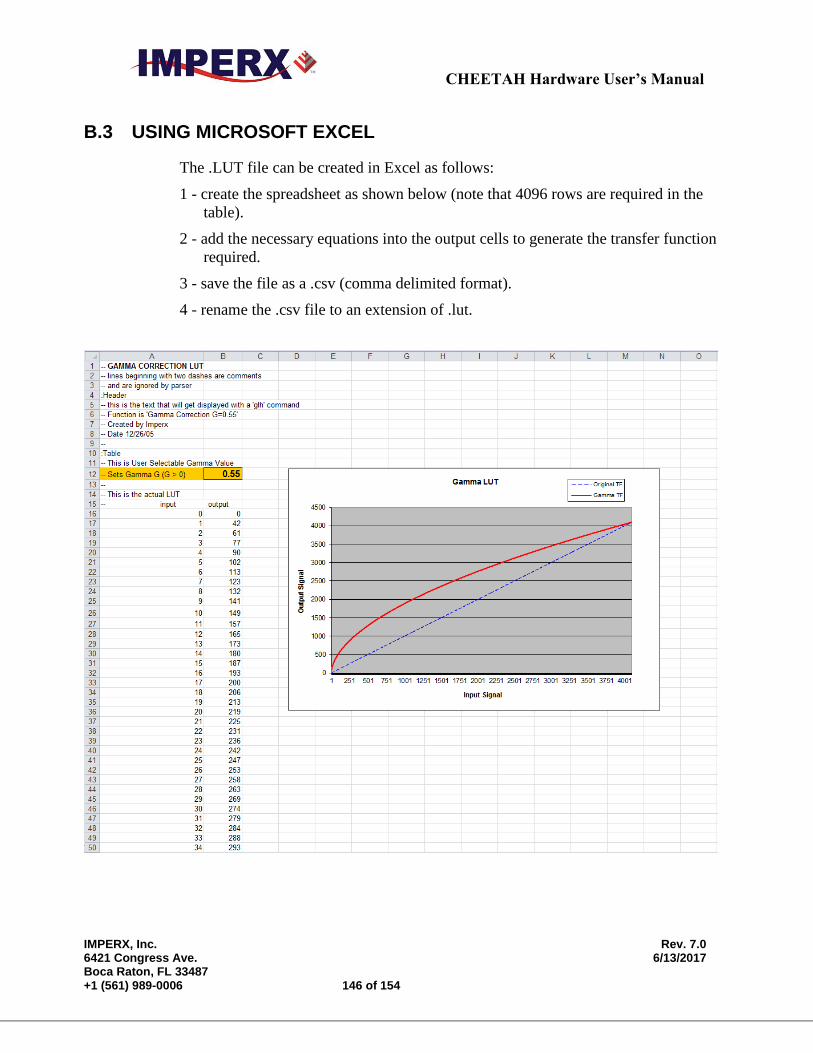
CHEETAH Hardware User’s Manual
IMPERX, Inc. Rev. 7.0 6421 Congress Ave. 6/13/2017 Boca Raton, FL 33487 +1 (561) 989-0006 146 of 154
B.3 USING MICROSOFT EXCEL
The .LUT file can be created in Excel as follows:
1 - create the spreadsheet as shown below (note that 4096 rows are required in the
table).
2 - add the necessary equations into the output cells to generate the transfer function
required.
3 - save the file as a .csv (comma delimited format).
4 - rename the .csv file to an extension of .lut.
CHEETAH Hardware User’s Manual
IMPERX, Inc. Rev. 7.0 6421 Congress Ave. 6/13/2017 Boca Raton, FL 33487 +1 (561) 989-0006 147 of 154
Appendix C – Creating DPC and HPC Tables
Creating DPC and HPC Tables
This appendix provides a reference on how to create a DPC and HPC table
using an ASCII editor.
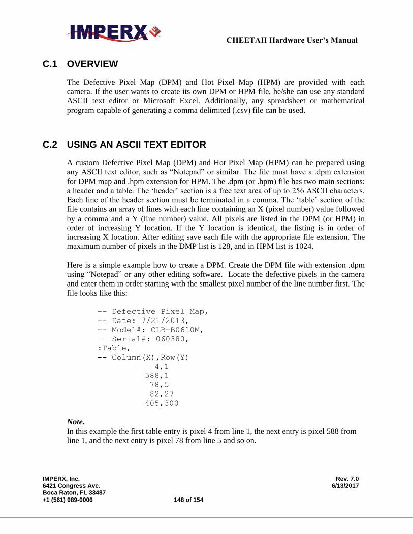
CHEETAH Hardware User’s Manual
IMPERX, Inc. Rev. 7.0 6421 Congress Ave. 6/13/2017 Boca Raton, FL 33487 +1 (561) 989-0006 148 of 154
C.1 OVERVIEW
The Defective Pixel Map (DPM) and Hot Pixel Map (HPM) are provided with each
camera. If the user wants to create its own DPM or HPM file, he/she can use any standard
ASCII text editor or Microsoft Excel. Additionally, any spreadsheet or mathematical
program capable of generating a comma delimited (.csv) file can be used.
C.2 USING AN ASCII TEXT EDITOR
A custom Defective Pixel Map (DPM) and Hot Pixel Map (HPM) can be prepared using
any ASCII text editor, such as “Notepad” or similar. The file must have a .dpm extension
for DPM map and .hpm extension for HPM. The .dpm (or .hpm) file has two main sections:
a header and a table. The ‘header’ section is a free text area of up to 256 ASCII characters.
Each line of the header section must be terminated in a comma. The ‘table’ section of the
file contains an array of lines with each line containing an X (pixel number) value followed
by a comma and a Y (line number) value. All pixels are listed in the DPM (or HPM) in
order of increasing Y location. If the Y location is identical, the listing is in order of
increasing X location. After editing save each file with the appropriate file extension. The
maximum number of pixels in the DMP list is 128, and in HPM list is 1024.
Here is a simple example how to create a DPM. Create the DPM file with extension .dpm
using “Notepad” or any other editing software. Locate the defective pixels in the camera
and enter them in order starting with the smallest pixel number of the line number first. The
file looks like this:
-- Defective Pixel Map,
-- Date: 7/21/2013,
-- Model#: CLB-B0610M,
-- Serial#: 060380,
:Table,
-- Column(X),Row(Y)
4,1
588,1
78,5
82,27
405,300
Note.
In this example the first table entry is pixel 4 from line 1, the next entry is pixel 588 from
line 1, and the next entry is pixel 78 from line 5 and so on.

CHEETAH Hardware User’s Manual
IMPERX, Inc. Rev. 7.0 6421 Congress Ave. 6/13/2017 Boca Raton, FL 33487 +1 (561) 989-0006 149 of 154
Appendix D – Software Installation - CL
Software Installation - CL
This appendix explains how to install the CHEETAH CamConfig software.
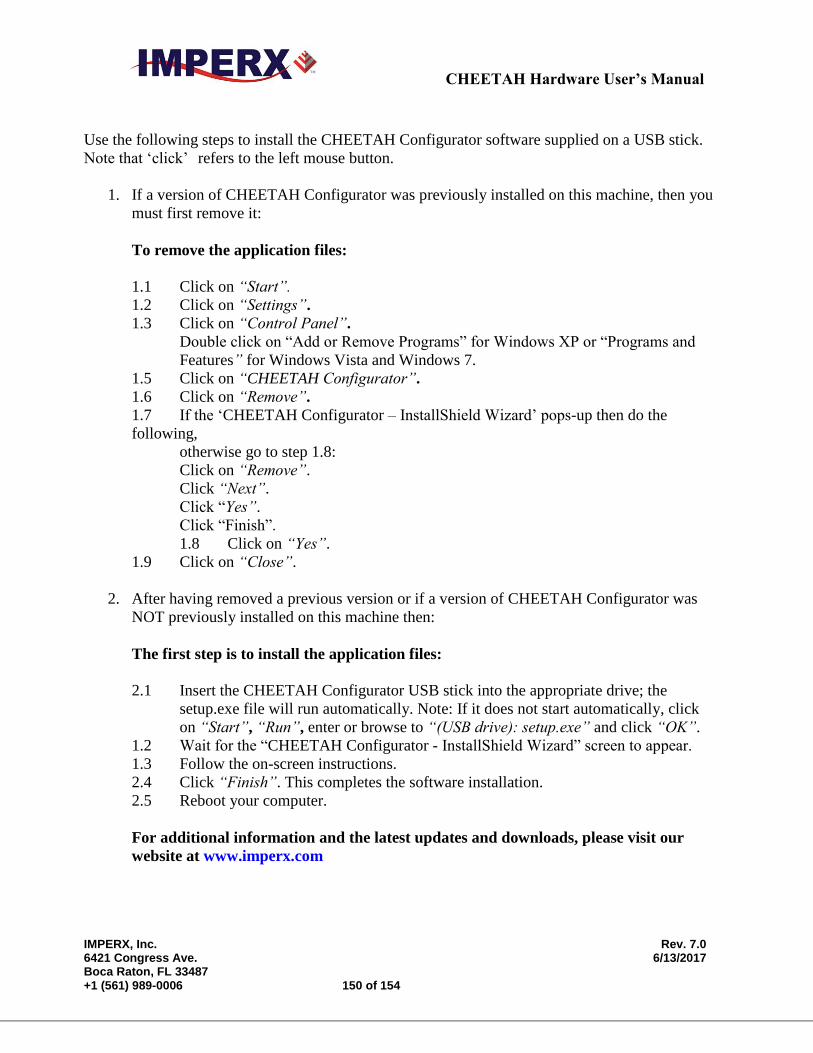
CHEETAH Hardware User’s Manual
IMPERX, Inc. Rev. 7.0 6421 Congress Ave. 6/13/2017 Boca Raton, FL 33487 +1 (561) 989-0006 150 of 154
Use the following steps to install the CHEETAH Configurator software supplied on a USB stick.
Note that ‘click’ refers to the left mouse button.
1. If a version of CHEETAH Configurator was previously installed on this machine, then you
must first remove it:
To remove the application files:
1.1 Click on “Start”.
1.2 Click on “Settings”.
1.3 Click on “Control Panel”.
Double click on “Add or Remove Programs” for Windows XP or “Programs and
Features” for Windows Vista and Windows 7.
1.5 Click on “CHEETAH Configurator”.
1.6 Click on “Remove”.
1.7 If the ‘CHEETAH Configurator – InstallShield Wizard’ pops-up then do the
following,
otherwise go to step 1.8:
Click on “Remove”.
Click “Next”.
Click “Yes”.
Click “Finish”.
1.8 Click on “Yes”.
1.9 Click on “Close”.
2. After having removed a previous version or if a version of CHEETAH Configurator was
NOT previously installed on this machine then:
The first step is to install the application files:
2.1 Insert the CHEETAH Configurator USB stick into the appropriate drive; the
setup.exe file will run automatically. Note: If it does not start automatically, click
on “Start”, “Run”, enter or browse to “(USB drive): setup.exe” and click “OK”.
1.2 Wait for the “CHEETAH Configurator - InstallShield Wizard” screen to appear.
1.3 Follow the on-screen instructions.
2.4 Click “Finish”. This completes the software installation.
2.5 Reboot your computer.
For additional information and the latest updates and downloads, please visit our
website at www.imperx.com

CHEETAH Hardware User’s Manual
IMPERX, Inc. Rev. 7.0 6421 Congress Ave. 6/13/2017 Boca Raton, FL 33487 +1 (561) 989-0006 151 of 154
Appendix E – Power Supplies
Power Supplies
This appendix has power supply models and connectors for CHEETAH series cameras.

CHEETAH Hardware User’s Manual
IMPERX, Inc. Rev. 7.0 6421 Congress Ave. 6/13/2017 Boca Raton, FL 33487 +1 (561) 989-0006 152 of 154
Model: PS12V04A CHEETAH standard power supply ordered separately.
Trigger & Strobe pigtail with Male BNC connectors
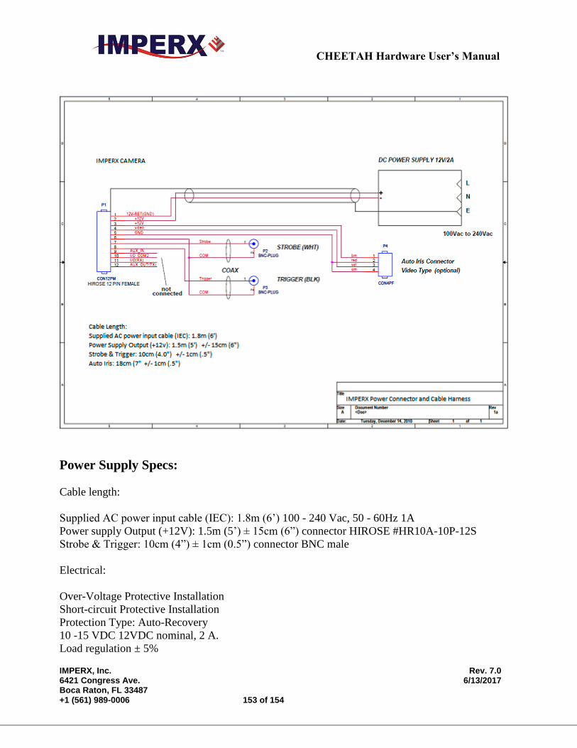
CHEETAH Hardware User’s Manual
IMPERX, Inc. Rev. 7.0 6421 Congress Ave. 6/13/2017 Boca Raton, FL 33487 +1 (561) 989-0006 153 of 154
Power Supply Specs:
Cable length:
Supplied AC power input cable (IEC): 1.8m (6’) 100 - 240 Vac, 50 - 60Hz 1A
Power supply Output (+12V): 1.5m (5’) ± 15cm (6”) connector HIROSE #HR10A-10P-12S
Strobe & Trigger: 10cm (4”) ± 1cm (0.5”) connector BNC male
Electrical:
Over-Voltage Protective Installation
Short-circuit Protective Installation
Protection Type: Auto-Recovery
10 -15 VDC 12VDC nominal, 2 A.
Load regulation ± 5%
CHEETAH Hardware User’s Manual
IMPERX, Inc. Rev. 7.0 6421 Congress Ave. 6/13/2017 Boca Raton, FL 33487 +1 (561) 989-0006 154 of 154
Ripple & Noise 1% Max.
Regulatory:
Class 1
Safety standards UL60950-1,EN60950-1,IEC60950-1
Safety (1) EMC UL/CUL,CE,TUV,DoIR+C-Tick,Semko,CCC,FCC
Safety (2) BSMI,FCC