checkSTRESS™ - SST SYSTEMS, Inc. · (for AVEVA’s PDMS) ... show !!checkSTRESS” on the command...
23
1 checkSTRESS™ ( for AVEVA’s PDMS) Introduction Under the “checkSTRESS” brand name, three products are available namely checkSTRESS (which generates only CAEPIPE input file), checkSTRESS II (which generates input files for both CAEPIPE and CAESAR II) and checkSTRESS Nuke (which generates input files for both CAEPIPE and PIPESTRESS). The following table lists the checkSTRESS products currently available for different 3D Plant Design Systems. Sl. No 3D Plant Design System Product Name Status 1 PDMS checkSTRESS Available 2 PDMS checkSTRESS II Available 3 PDMS checkSTRESS Nuke Available 4 CADMATIC checkSTRESS Available 5 CADMATIC checkSTRESS II Available 6 CADMATIC checkSTRESS Nuke Available 7 PDS checkSTRESS Available 8 PDS checkSTRESS II Available 9 PDS checkSTRESS Nuke Available 10 PCF checkSTRESS Available 11 PCF checkSTRESS II Available 12 PCF checkSTRESS Nuke Available This document describes the common features of checkSTRESS product(s) currently available for PDMS. Details related to the generation of CAESAR II input files by checkSTRESS II and PIPESTRESS input files by checkSTRESS Nuke are covered in a separate document titled “CIIModel.pdf” and “PSModel.pdf” respectively.
-
Upload
nguyentram -
Category
Documents
-
view
221 -
download
1
Transcript of checkSTRESS™ - SST SYSTEMS, Inc. · (for AVEVA’s PDMS) ... show !!checkSTRESS” on the command...
1
checkSTRESS™ (for AVEVA’s PDMS)
Introduction
Under the “checkSTRESS” brand name, three products are available namely checkSTRESS (which
generates only CAEPIPE input file), checkSTRESS II (which generates input files for both CAEPIPE and
CAESAR II) and checkSTRESS Nuke (which generates input files for both CAEPIPE and PIPESTRESS).
The following table lists the checkSTRESS products currently available for different 3D Plant Design
Systems.
Sl. No 3D Plant Design System Product Name Status
1 PDMS checkSTRESS Available
2 PDMS checkSTRESS II Available
3 PDMS checkSTRESS Nuke Available
4 CADMATIC checkSTRESS Available
5 CADMATIC checkSTRESS II Available
6 CADMATIC checkSTRESS Nuke Available
7 PDS checkSTRESS Available
8 PDS checkSTRESS II Available
9 PDS checkSTRESS Nuke Available
10 PCF checkSTRESS Available
11 PCF checkSTRESS II Available
12 PCF checkSTRESS Nuke Available
This document describes the common features of checkSTRESS product(s) currently available for PDMS.
Details related to the generation of CAESAR II input files by checkSTRESS II and PIPESTRESS input files
by checkSTRESS Nuke are covered in a separate document titled “CIIModel.pdf” and “PSModel.pdf”
respectively.

2
Installing Program
1 To install checkSTRESS (for PDMS) on Windows OS, load the product CD supplied and execute the
followings steps:
2 Browse the CD, and run the program "Setup.exe" and follow the instructions as they appear on the
screen.
3 Add the path of the installed directory to the "pmllib" path of the PDMS.
4 For example SET PMLLIB=C:\Progra~1\SST_Systems\checkSTRESSPDMS %1\pmllib (assuming
checkSTRESS is installed in the directory C:\Program Files\SST_Systems\checkSTRESSPDMS).
Note: For the program to work properly, avoid using space or special characters while entering the path
or file name.
5 Define an environmental variable with name as “checkSTRESS_PDMS” and the value as checkSTRESS
Installation path.
For example, set the value as “C:\Progra~1\SST_Systems\checkSTRESSPDMS” (assuming that the
product is installed in the directory “C:\ProgramFiles\SST_Systems\checkSTRESSPDMS).
6 The environment variables required by PDMS are also required for checkSTRESSPDMS. The PDMS
environment must exist as outlined in the appropriate PDMS Installation Guide.
7 Load PDMS and enter the Lexicon Module as a user who has Read-Write access to DICT Database and run the datal file checkSTRESS.DAT, to create the UDA: SUPCODE for ATTA elements, UDA :NX, :NY, :NZ and :NAL for Nozzle elements, UDA: :HNX, :HNY, :HNZ, :TNX, :TNY, :TNZ, :HNAL and :TNAL for Branch elements.
How to use checkSTRESS?
1 Add the ZONE/PIPES/BRANCHES need to be checked for stress using “Add CE” or CE Members”
button.
2 Branches selected for transfer need to be checked for the following.
TEMP, PRES attributes of the BRAN element
Each branch should have a valid PH OD
Each branch in the network should have a valid HSTU
Each branch should have a component
It is recommended to perform “DATA CONSISTENCY CHECK” for all Pipes/Branches selected for
transfer.
3 For transferring the support details, ATTA’s have to be created at support locations and the UDA
(:SUPCODE) should be set a value as given in the field #1 (i.e., “PdSupport” ) of the access db
“SupportType.mdb”.

3
4 To use checkSTRESS (for PDMS), type “show !!checkSTRESS” on the command line of PDMS Design
Module. The following form appears,
Specify/Change the Name of the file if you wish. Do not leave a blank space while giving the file
name / path. Program checks and generates error, if finds a space in the file name / path.

4
Select the Input units used in Project while entering “Pressure”, “Temperatures” and “Weight”
using the options as shown in the figure above. Please note, selecting wrong input units used in
project will results in incorrect output.
Select the piping code to be used for the analysis of the model from the list box.
Enter/modify the Static Seismic g’s. Available only for checkSTRESS Nuke.
Enter the Starting Node number and Node increment value in the appropriate field. By default,
the Starting Node number and Node increment are set to 10 and 10 respectively.
Enter the Specific Gravity of operating fluid with respect to water. By default the specific gravity
is set to 1.0.
Select Default Hanger to be used in checkSTRESS model. This Hanger type will be used only
when the hanger type in checkSTRESS corresponding to Plant Design hanger is not specified
/available in the Mapping DB. For details on transferring support from Plant Design to
checkSTRESS, refer Appendix D of checkSTRESS User’s manual (checkSTRESS.pdf).
When the “Identify Support ATTA’s with ATTYPE attribute set as” is entered with a Keyword,
then it will transfer support locations and its information from PDMS, only when the attribute
“ATTYPE” is filled with the string that matches the Keyword entered in the form. On the other
hand, leaving this text box empty (unfilled) will transfer all the ATTA from the PDMS for the
selected Pipes/Branches without checking its “ATTYPE” attribute. For example, if the Keyword is
specified as “SUPP” then the program will include ATTA’s for transfer, only when the ATTYPE
attribute is filled with the same Keyword “SUPP”, otherwise, it excludes them from transfer.
Select the units to be used for the checkSTRESS model.
Selecting the option “SI Units” transfers the Pipes/Branches details in SI units i.e. Length related
dimensions such as OD, Nominal Size etc in mm, Temperature in Deg C, Pressure in bar,
Weight in Kg, Density in Kg/m3, Translational Stiffness in N/mm, Rotational stiffness in N-m/deg
to the neutral file.
Similarly Selecting the option “ENGLISH Units” transfers Pipes/Branches details in ENGLISH
units i.e. Length related dimensions such as OD, Nominal Size etc in Inch, Temperature in Deg
F, Pressure in psi, Weight in lb, Density in lb/in3, Translational Stiffness in lb/in, Rotational
Stiffness in lb-in/deg to the neutral file.
Select the Boundary Conditions to be used from the form shown above. Refer the section titled
“Reference” for details.
If the user wishes to eliminate those elements whose Nominal size (NS) is less than 50mm / 2in,
then they can specify the value as “50” for SI Units and “2” for English Units in the field “Process
elements, if dia >”. In other words, the program will process only those elements whose nominal
size is greater than the value specified in the field above.

5
Specify how the 3 Way and 4 Way Valves to be transferred to checkSTRESS. Refer the section
titled “Reference” for details.
Navigate to the required ZONE/PIPE/BRANCH through the member list as shown in the figure
above.
Press the button “Add CE” to include and to perform the Stress Check for the selected
ZONE/PIPE/BRANCH.
User can also use the button “CE Members” to include all the members of SITE/ZONE/PIPE and
then exclude a few members using the “Remove” button if required. For example, if you wish to
add 8 PIPES out of 10 PIPES under a particular ZONE, navigate to the ZONE and press the
button “CE Members”. Highlight the PIPE (one at a time) in the included list and press the button
“Remove” to exclude them.
Choose the Global Vertical Axis for checkSTRESS model from the vertical Axis option. By
default, “Z Axis” shall be taken as Global Vertical Axis if not specified.
Note: Since PDMS always uses vertical global axis as “Z” and Stress Engineers from
different parts of the world use different coordinate systems, it is recommended that the
designers should consult with the stress department and choose the “Vertical Global
Axis” before saving the stress model in CAEPIPE/CAESAR II format (for Stress
department to carry out the detailed analysis). On the other hand, for performing the first
level stress check using checkSTRESS, designers shall continue to use “Z” as Global
Vertical Axis.
Press the button “Apply” to perform the Stress Check.

6
5 Response Spectrum load data can be added through Edit Layout > Misc > Response Spectrum. Once
added, the same can be applied in stress model through Edit Layout > Loads > Spectrum. Refer to
Appendix B for details on adding Spectrum.
6 Figure above shows the stress contour plot for the Expansion case. Sustained Stress plot can be seen
by selecting the option “Sustained Stress (Weight + Pressure)” as shown in the figure right above.
7 Designers can also plot and view the deflected shapes of the piping system under different loading
conditions using the options available in the heading titled “Deflected Shape” as shown in the figure on
the right above.
8 Designers can review the Nozzle / Anchor Qualification using the Option “Show Summary”.
9 Hanger selected by checkSTRESS for “to be designed” hangers can be viewed by selecting the option
“Show Hanger Report”.
10 Designers can generate the CAEPIPE mod file using the option “CAEPIPE 7.2x mod” for the Stress
Department to carry out the detailed analysis including stress report preparation.
11 Similarly, in order for the Stress Department to carry out the detailed analysis including stress report
preparation, designers can generate CAESAR II input files in checkSTRESS II product and
PIPESTRESS input files in checkSTRESS Nuke product respectively, by selecting the appropriate option
from the dialog box as shown above.
12 Using the option “Print”, designers can print the model data, code compliance for ten (10) high stress
nodes, Nozzle / Anchor Qualification and Status of Resting Support / Limit Stops.
13 Mode shapes reports using the option “Show Modes” are available only for checkSTRESS Nuke product.
Limitations
The following are not transferred to checkSTRESS from PDMS at this time. However user can add these in
checkSTRESS through Edit Layout->Misc->Section
1 Corrosion allowance and Mill tolerance.
2 Lining Density and Lining Thickness.
Reference
Loads
Temperature and Pressure values entered at Pipe/Branch level via TEMP and PRES attribute shall be
transferred to checkSTRESS. Hence, user should fill these attributes with appropriate values depending
upon the Units of transfer. I.e., If you wish to transfer the model in SI units, then the value entered for
Temperature and Pressure should be in Deg C and kg/cm2 respectively. On the other hand, if you wish to
transfer the model in English Units, then the Temperature and Pressure values shall be entered in Deg F and
psi respectively.

7
User can also add / modify the Temperature and Pressure values in checkSTRESS through Edit Layout-
>Misc->Loads.
Fluid Density
Even though the provision is available in PDMS Propcon Database to enter the Fluid density, most of the
users do not use such facility. Hence, provision is given to specify the Specific Gravity of the fluid (with
respect to water) during the transfer of the model.
Weight
The weights of Valves, Instruments, Flanges, etc. are extracted from the Propcon Database through the
“Cweight” attribute. If defined/available in the Propcon Database, the program extracts the information and
transfer to checkSTRESS. Care should be taken while filling the “Cweight” attribute in Propcon. i.e., the
values should be specified in Kg / lb, to transfer the same in SI / English units respectively.
User can add / modify the weight of components by selecting the component type such as Valve, Rigid,
Flange, etc. through Edit Layout->Window->List.
Wall Thickness
Since the Wall thickness of the Piping components is generally not available in PDMS, they are set to 0.0 by
default. However, user can transfer the Wall Thickness information to checkSTRESS properly from PDMS (if
they are specified) by modifying the variables defined in the program. Refer Appendix A for details on
modifying the program to extract Wall Thickness from PDMS.
User can also specify wall thickness of piping components through Mapping DB (Code.mdb) supplied along
with the project. For details refer to Appendix C of checkSTRESS User’s Manual (checkSTRESS.pdf).
In addition to the above options, user can also modify the Wall thickness of the piping components directly in
checkSTRESS through Edit Layout->Misc->Section.
OD and Nominal Size
OD and Nominal Size are extracted from the Paragon Database of PDMS. For reducers, the arrive OD and
Thickness shall be transferred to OD1 and Thk1 of the element in checkSTRESS and the leave OD and
Thickness shall be transferred as OD2 and Thk2 of the element in checkSTRESS.
User can also modify the OD and Nominal size of the piping components directly in checkSTRESS through
Edit Layout->Misc->Section.
Boundary Conditions
Selecting the option “Anchor end if connected to Nozzle or Pipelines” will Anchor the Pipe Ends only when
they are connected to a Nozzle or Pipelines, otherwise it leaves them as Free. On the other hand, if one end
of the pipe is connected to a Nozzle and the other end of Pipe is connected to a Branch and if that Branch is
not included as the part of the Stress model, then the program will anchor both the end automatically.
For more clarity, consider the following examples. If one end of the pipe is connected to a Pump Nozzle and
the other end is not connected to any Nozzle or Pipeline, then the program will anchor the first end and leave
8
the other end as free (i.e., do not create any support). On the other hand, if one end of the pipe is connected
to a Nozzle and the other end is connected to a Branch and that Branch is not included in the Stress model,
then the program will anchor both the ends automatically.
Similarly selecting the option “Anchor all Free Ends” will “Anchor” all the ends of the Branches automatically
irrespective of whether they are connected to Nozzle or Pipelines.
In addition to the above, user can also add / modify supports in piping system in checkSTRESS directly
through Edit Layout->Misc->Data Types.
Supports
Supports locations and its information are included for transfer from PDMS when the following conditions are
met.
Step 1: Include/Exclude ATTA’s for Transfer
Define ATTA and fill the attribute “ATTYPE” with an appropriate Keyword. Use the same Keyword in the text
box “Identify Support ATTA’s with ATTYPE attribute set as” (as shown in figure above). Mismatching of
Keywords will exclude the ATTA’s from transfer (or) fill the attribute “ATTYPE” with an appropriate Keyword
and leave the text box “Identify Support ATTA’s with ATTYPE attribute set as” empty (unfilled) to include all
ATTA’s for Transfer.
Step 2: Transfer Support Details
The program performs the following for transferring the support details to checkSTRESS.
Checks for user defined attribute (UDA) “:SUPCODE”. If available, then reads the details of support
from this attribute and write them to the neutral file.
If not available, then checks for user defined attribute “:KPSUPCODE”. If available, then read the
details from this attribute and transfer to checkSTRESS. Please note, this feature is included for
users who had used older versions of checkSTRESS. i.e., User who had used the older version of
checkSTRESS can continue to use the same user defined attribute “:KPSUPCODE” to transfer the
support details to checkSTRESS, without reentering the values to the new attribute.
Lastly, if both the attributes are not available in PDMS, then the program will read the support details
from the “STEXT” attribute of ATTA and transfer the same to checkSTRESS. This can be used in
situations where, the users do not have write access to Dictionary Database of PDMS to create the
User Defined attribute.
Any of the attributes defined above should be set a value as given in the field #1 i.e., “PdSupport” of the
access db “SupportType.mdb”, when the user selects the option “Use Mapping DB” for transferring the
support details to checkSTRESS. Otherwise, the attribute should be filled with values as specified in
Appendix E of checkSTRESS User’s Manual supplied along with the product. For details on transferring
supports “Without Using Mapping DB”, refer to Appendix D of checkSTRESS User’s Manual
(checkSTRESS.pdf).

9
In addition to the above, user can also add / modify supports in piping system in checkSTRESS directly
through Edit Layout->Misc->Data Types.
Material
Material description entered at XTEXT attribute of SMTE is extracted from the Paragon Database and the
material property is then obtained from the intermediate mapping db. For more details, refer Appendix B of
checkSTRESS User’s Manual supplied along with the product.
User can add / modify the Material properties in checkSTRESS through Edit Layout->Misc->Materials.
Thermal Anchor Movement (TAM)
Thermal Anchor Movement (TAM) values entered at UDA :NX, :NY, and NZ in global X, Y and Z directions
respectively at Equipment Nozzle where the piping layout (selected for transfer) is connecting to. These
values are then transferred to checkSTRESS. TAM values should be defined in “mm” for PDMS projects in
SI units and in “Inch” for PDMS project in English units.
If the Equipment Nozzle to which the Piping Layout is connecting to is not modeled in PDMS, then these
TAM values can be entered at UDA :HNX, :HNY and :HNX or :TNX, :TNY and :TNZ at PDMS Branch
corresponding to Head or Tail of pipe run. In other words, TAM at starting of the Pipe run should be entered
at :HNX, :HNY and :HNZ of PDMS Branch. On the other hand, TAM at the end of the Pipe run should be
entered at :TNX, TNY and TNZ of PDMS Branch.
User can also add / modify the Thermal Anchor Movement values through Edit Layout option. i.e., Click Edit
Layout then select “Anchor” and select “Edit data” through Layout > Edit. From the dialog box shown, click on
“Specified Displacement” and enter the TAM values.
User defined Equipment Nozzle Allowable Loads
Equipment Nozzle Allowable Loads (forces and moments) provided by the equipment manufacturer or
calculated using Applicable codes / Finite Element Methods can be entered at UDA :NAL in global X, Y and
Z directions at Equipment Nozzle in the format FX, FY, FZ, MX, MY and MZ. These values should be
separated using “,”. Please note, the force values should be entered in “lb” for English units and in “N” for SI
units. Similarly, the moment values should be entered in “ft-lb” for English units and in “Nm” for SI units.
If the Equipment Nozzle to which the Piping Layout is “Connecting To” is not modeled in PDMS, then these
Equipment Nozzle Allowable Loads can be entered at UDA :HNAL or :TNAL at PDMS Branch corresponding
to Head or Tail of the Pipe run. In other words, Allowable Loads at starting of the Pipe run should be entered
at :HNAL of PDMS Branch. On the other hand, Allowable Loads at the end of the Pipe run should be entered
at :TNAL of PDMS Branch.
Example:
For Nozzle, enter the values of FX, FY, FZ, MX, MY and MZ as “:NAL ‘3000,3000,6000,500,500,2000’”
For PDMS Branch Head, enter the values of FX, FY, FZ, MX, MY and MZ as “:HNAL
‘3000,3000,6000,500,500,2000’” and

10
For PDMS Branch Tail, enter the values of FX, FY, FZ, MX, MY and MZ as “:HNAL
‘3000,3000,6000,500,500,2000’”
The allowables thus defined are compared against calculated loads and shown / printed in Support Load
Summary outputs (can be viewed / printed through “Show Summary” option). If the calculated loads exceed
the allowables, they are highlighted in red.

11
PDMS to checkSTRESS component Mapping
The types of components available in PDMS are simulated as tabulated below in checkSTRESSPDMS.
PDMS Component
Description
Connection Points Component in
checkSTRESS
Keyword used
in Neutral File
Cap
Butt weld
Rigid Element RB
Cap compression
Rigid Element RB
Cap Screwed
Rigid Element RB
Cap Socket Weld
Rigid Element RB
Closure
Pipe Block
Rigid Element RB
Pipe Block Variable Length
Rigid Element RB
Coupling
Nipple – Screwed, Coupling
Compression, Coupling
Screwed, Coupling Socket
weld, Butt weld Elbolet, Socket
Weld Elbolet, Screwed Elbolet
Reducer Concentric RD
Cross
Butt Weld, Socket Weld,
Compression, Flanged,
Screwed
Four Pipes with Branch
SIF (Welding TEE) CR

12
PDMS Component
Description
Connection Points Component in
checkSTRESS
Keyword used
in Neutral File
Set on, Set on Reinforced
Four Pipes with Branch
SIF (Welding TEE) CR
Blind Flange
Flange – Blind
Rigid Element or Pipe
with Flange FL
Flange - Reducing Concentric
Rigid Element or Pipe
with Flange FL
Flange Reducing Eccentric
NA NA
Fixed Length Tube
Fixed length Pipe with Flanged
ends and without Flanged ends.
Pipe PI
Lap Joint and Stub End
Lap Joint Ring Loose
Rigid Element or Pipe
with Flange FL
Lap Joint Stub End Loose
Rigid Element or Pipe
with Flange FL
PCOMponent
Block – Angle
Pipe PI
Expansion Bellows, Flame
Trap, Flexible Hose, Hose
Coupling, Non – Category item,
Pipe PI

13
PDMS Component
Description
Connection Points Component in
checkSTRESS
Keyword used
in Neutral File
Restrictor Plate, Tundish
Plug
Pipe PI
Sight Glass
Pipe PI
Slip Plate, Slip Ring, Spectacle
Blind
Pipe PI
Reducer Concentric
Reducer Concentric Butt Weld,
Fabricated from Plate, Swaged
from Pipe, Compression,
Flanged, Fabricated from Plate
Flanged, Swaged from Pipe
Flanged, Nipple, Screwed,
Socket Weld Bush, Socket
Weld & Special Reducing
Flange
Reducer Concentric RD
Reducer Concentric with a Butt
Weld Connection, Fabricated
Plate Connection, Connection
Swaged from Pipe, Connection
Flanged, Connection Fabricated
from Plate Flanged, Connection
Swaged from Pipe Flanged,
Screwed Connection and
Connection Socket Weld
Reducer Concentric RD
Reducer Eccentric
Reducer eccentric Buttweld,
Fabricated from Plate and
Swaged from Pipe.
Reducer Eccentric ER

14
PDMS Component
Description
Connection Points Component in
checkSTRESS
Keyword used
in Neutral File
Reducer Eccentric with a
Connection Butt Weld,
Connection Fabricated from
Plate, Connection Swaged from
Pipe, Connection Flanged,
Connection fabricated from
Plate Flanged and Connection
Swaged from Pipe Flanged
NA NA NA
Eccentric Screwed, Flanged,
Fabricated from Plate Flanged
and Swaged from Pipe Flanged
Reducer Eccentric
ER
TRAP
Trap – In Line
Pipe
PI
Trap – Angle
Pipe PI
Trap – Offset, Trap – Return NA NA NA
UNION
Union – Screwed, Socket Weld
Rigid Element RB
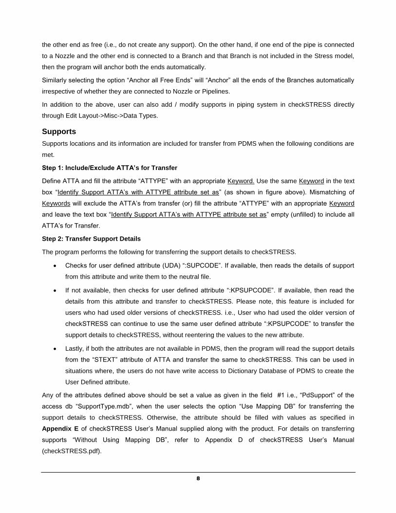
TEE or OLET
Olet - Half Coupling, Nipolet
(Screwed, Plain Ended),
Sockolet, Thredolet, Weldolet,
Tee- Set-on, Set-on Reinforced
and Tee Pulled
Pipe(s) with Branch SIF
(Welding TEE) or
(Weldolet)
TU/TW/TF/TO
15
PDMS Component
Description
Connection Points Component in
checkSTRESS
Keyword used
in Neutral File
Olet – Latrolet (Butt Weld,
Screwed & Socket Weld)
Pipe(s) with Branch SIF
(Welding TEE) or
(Weldolet)
TU/TW/TF/TO
Olet – Instrument Flanged, Tee
– Butt Weld, Compression,
Flanged, Screwed, Socket
Weld, Swept Branch Butt Weld,
Swept Branch Flanged, Swept
Branch Compression and
Swept Branch Socket Weld
Pipe(s) with Branch SIF
(Welding TEE) or
(Weldolet)
TU/TW/TF/TO
Valve
Valve – Angle (Pressure
Reducing, Relief/Vent,
Valve VA
Valve – Ball, Basic, Butterfly,
Cock, Diaphragm, Gate, Globe,
Needle, Plug, Pressure
Reducing, Relief/Vent and Slide
Valve VA
Valve – Check
Valve VA
VENT
Rupture Disk
Rigid Element RB
Four Way Valve
Valve – 4 Way
Four Rigid Elements or
Four Pipes with
Concentrated Mass
4W
16
PDMS Component
Description
Connection Points Component in
checkSTRESS
Keyword used
in Neutral File
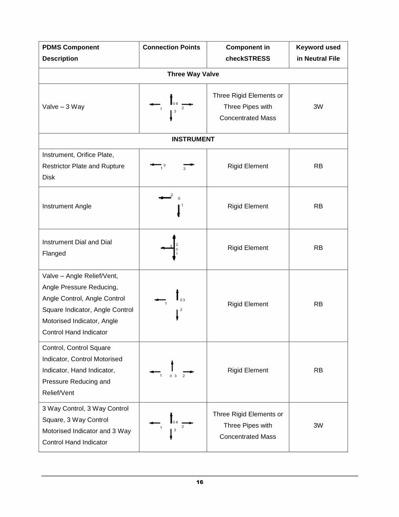
Three Way Valve
Valve – 3 Way
Three Rigid Elements or
Three Pipes with
Concentrated Mass
3W
INSTRUMENT
Instrument, Orifice Plate,
Restrictor Plate and Rupture
Disk
Rigid Element RB
Instrument Angle
Rigid Element RB
Instrument Dial and Dial
Flanged
Rigid Element RB
Valve – Angle Relief/Vent,
Angle Pressure Reducing,
Angle Control, Angle Control
Square Indicator, Angle Control
Motorised Indicator, Angle
Control Hand Indicator
Rigid Element RB
Control, Control Square
Indicator, Control Motorised
Indicator, Hand Indicator,
Pressure Reducing and
Relief/Vent
Rigid Element RB
3 Way Control, 3 Way Control
Square, 3 Way Control
Motorised Indicator and 3 Way
Control Hand Indicator
Three Rigid Elements or
Three Pipes with
Concentrated Mass
3W

17
PDMS Component
Description
Connection Points Component in
checkSTRESS
Keyword used
in Neutral File
4 Way Control Square Indicator,
4 Way Control, 4 Way Control
Motorised Indicator, 4 Way
Control Hand Indicator
Four Rigid Elements or
Four Pipes with
Concentrated Mass
4W
ELBOW or BEND
Elbow – Butt Weld(90 and 45
Deg), Screwed with Female
Ends, Elbow Compression,
Screwed with Male Ends, Elbow
Socket Weld, Elbow Reducing,
Bend – Mitre, Lobster Back Butt
weld and Lobster Back Bend
and Pulled
Bend EL
Butt Weld with a Connection,
Compression with a
Connection, Screwed Female
with a Connection, Socket Weld
with a Connection, Bend
Flanged with a Connection,
Bend – Mitre with a Connection
Flanged, Butt Weld Bend –
Mitre with a Connection,
Lobster Back with a Connection
and Pulled with a Connection
Pipes with Branch SIF
(Welding TEE) TW
Butt Weld 180 Deg Return,
Flanged 180 Deg Return and
Pulled 180 Deg Return
Bend EL
FILTER
Filter/Strainer- Straight Through
Rigid Element RB

18
PDMS Component
Description
Connection Points Component in
checkSTRESS
Keyword used
in Neutral File
Filter / Strainer Angle
Rigid Element RB
Flange
Flange Blind, Flared/Loose
Backing, Flange Backing,
Flange Reducing Concentric,
Screwed, Slip On, Slip On with
‘J’ Type Weld, Socket Weld and
Weld Neck
or
Rigid Element or Pipe
with Flange
FL
Orifice Slip On Flange and
Orifice Weld Neck
Rigid Element with
Tapping OF
19
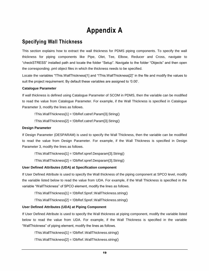
Appendix A
Specifying Wall Thickness
This section explains how to extract the wall thickness for PDMS piping components. To specify the wall
thickness for piping components like Pipe, Olet, Tee, Elbow, Reducer and Cross, navigate to
“checkSTRESS” installed path and locate the folder “Setup”. Navigate to the folder “Objects” and then open
the corresponding .pml object files in which the thickness needs to be specified.
Locate the variables “!This.WallThickness[1] and “!This.WallThickness[2]” in the file and modify the values to
suit the project requirement. By default these variables are assigned to ‘0.00’.
Catalogue Parameter
If wall thickness is defined using Catalogue Parameter of SCOM in PDMS, then the variable can be modified
to read the value from Catalogue Parameter. For example, if the Wall Thickness is specified in Catalogue
Parameter 3, modify the lines as follows.
!This.WallThickness[1] = !DbRef.catref.Param[3].String()
!This.WallThickness[2] = !DbRef.catref.Param[3].String()
Design Parameter
If Design Parameter (DESPARAM) is used to specify the Wall Thickness, then the variable can be modified
to read the value from Design Parameter. For example, if the Wall Thickness is specified in Design
Parameter 3, modify the lines as follows.
!This.WallThickness[1] = !DbRef.spref.Desparam[3].String()
!This.WallThickness[2] = !DbRef.spref.Desparam[3].String()
User Defined Attributes (UDA) at Specification component
If User Defined Attribute is used to specify the Wall thickness of the piping component at SPCO level, modify
the variable listed below to read the value from UDA. For example, if the Wall Thickness is specified in the
variable “WallThickness” of SPCO element, modify the lines as follows.
!This.WallThickness[1] = !DbRef.Spref.:WallThickness.string()
!This.WallThickness[2] = !DbRef.Spref.:WallThickness.string()
User Defined Attributes (UDA) at Piping Component
If User Defined Attribute is used to specify the Wall thickness at piping component, modify the variable listed
below to read the value from UDA. For example, if the Wall Thickness is specified in the variable
“WallThickness” of piping element, modify the lines as follows.
!This.WallThickness[1] = !DbRef.:WallThickness.string()
!This.WallThickness[2] = !DbRef.:WallThickness.string()

20
Appendix B
Response Spectrum

21
.Spectrums.
A (uniform response) spectrum is a table of maximum response versus natural frequency for a specific excitation in single degree-of-freedom systems. You can input spectrums in three ways:
1. Input spectrums directly into the model.
2. Create a spectrum library and load spectrums from it.
3. Input spectrums from a text file.
When you use the first two methods, you may use menu Options > Spectrum command to set the different units for the X- and the Y-axes, and also choose the interpolation method.
1. Input spectrums directly into the model
Select Spectrums from the Misc menu. You are shown the List window for spectrums. Start typing pairs of values into it. The frequencies or periods do not have to be in any order; checkSTRESS will sort them later. You can input as many pairs of values as required.
22
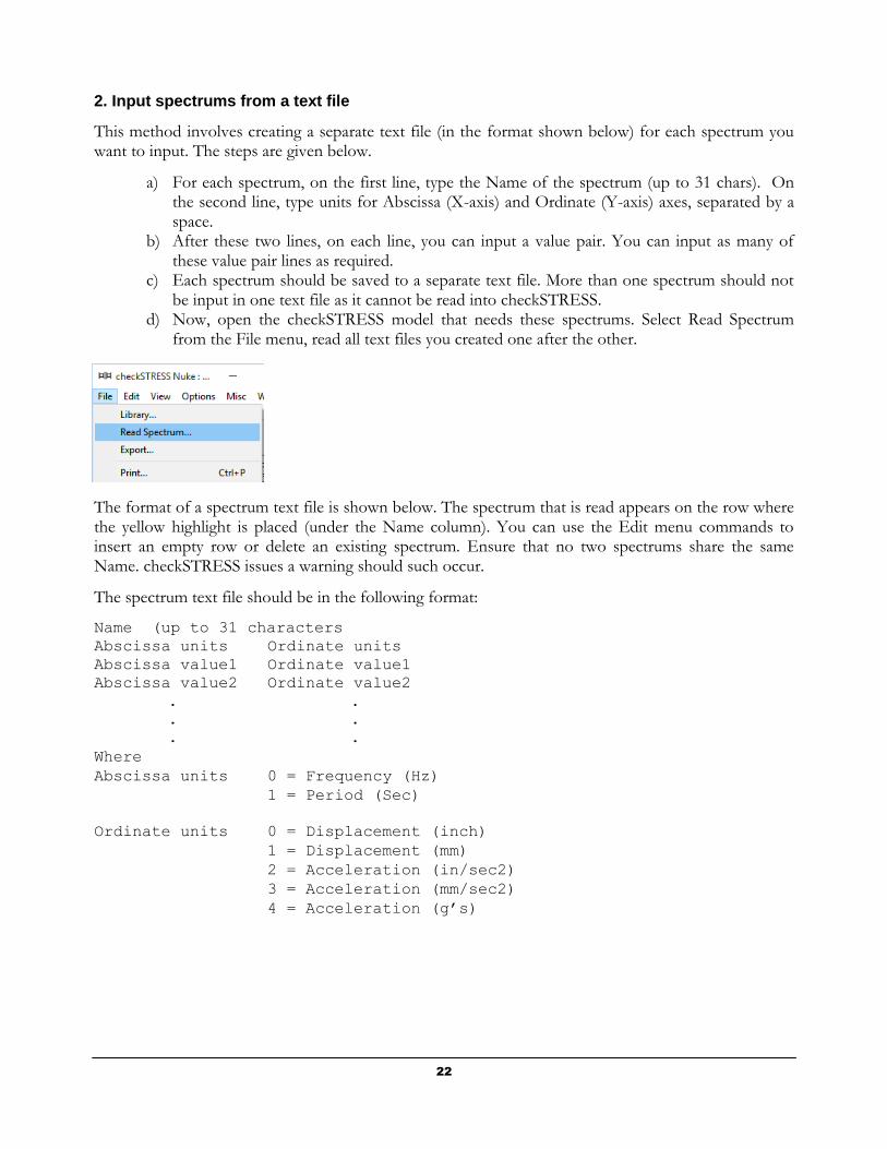
2. Input spectrums from a text file
This method involves creating a separate text file (in the format shown below) for each spectrum you want to input. The steps are given below.
a) For each spectrum, on the first line, type the Name of the spectrum (up to 31 chars). On the second line, type units for Abscissa (X-axis) and Ordinate (Y-axis) axes, separated by a space.
b) After these two lines, on each line, you can input a value pair. You can input as many of these value pair lines as required.
c) Each spectrum should be saved to a separate text file. More than one spectrum should not be input in one text file as it cannot be read into checkSTRESS.
d) Now, open the checkSTRESS model that needs these spectrums. Select Read Spectrum from the File menu, read all text files you created one after the other.
The format of a spectrum text file is shown below. The spectrum that is read appears on the row where the yellow highlight is placed (under the Name column). You can use the Edit menu commands to insert an empty row or delete an existing spectrum. Ensure that no two spectrums share the same Name. checkSTRESS issues a warning should such occur.
The spectrum text file should be in the following format:
Name (up to 31 characters
Abscissa units Ordinate units
Abscissa value1 Ordinate value1
Abscissa value2 Ordinate value2
. .
. .
. .
Where
Abscissa units 0 = Frequency (Hz)
1 = Period (Sec)
Ordinate units 0 = Displacement (inch)
1 = Displacement (mm)
2 = Acceleration (in/sec2)
3 = Acceleration (mm/sec2)
4 = Acceleration (g’s)

23
Example file
Test Spectrum
0 2
1 190
2 220
3 250
4 1932
5 1000
6 1800
. .
. .
Analysis note:
While analyzing the response spectrum case, when a mode (frequency or period) falls outside the spectrum table, checkSTRESS issues a warning and uses the value corresponding to the closest frequency or period in the spectrum table (for example, checkSTRESS uses the value corresponding to the lowest frequency if the calculated frequency is lower than the lowest in the spectrum table or uses the value corresponding to the highest frequency if the calculated frequency is higher than the highest in the spectrum table).
Once you are done inputting the different spectrums using any one of the three methods, you need to input the Spectrum load itself under the menu Loads > Spectrum in the Layout window. Details on inputting the Spectrum Load are provided earlier under the Loads menu.