Orthopedic Pitfalls in the ED--Lisfranc Fracture-Dislocation

S U R G I C A L T E C H N I Q U E
CHARLOTTE™ LisfrancRecontruction System

2
Introduction
Indications and Contraindications
CHARLOTTE™ Lisfranc System Design Rationale
Surgical Goals
System Basics
Instrumentation
Implants
Indications and Contraindications
Surgical Technique For CHARLOTTE™ Lisfranc Bone Screw
Exposure and Joint Preparation
Alignment of “Home Run” Screw and Anatomical Joint Reduction
K-Wire Placement
Screw Length Determination
Screw Canal Drilling and Preparation
Home Run Screw Placement
Additional Screw Placement
Surgical Technique For CHARLOTTE™ Lisfranc Locking Plates
Plate Placement and Preparation
2.7mm Screw Preparation
2.7mm Screw Placement
Ordering Information
Preface 3
Chapter 1 4
Chapter 2 4
4
4
4
4
Chapter 3 5
5
5
6
6
6
7
7
8
Chapter 4 8
8
9
10
Appendix 10
Proper surgical procedures and techniques are the responsibility of the medical professional. The following guidelines are furnished for information purposes only. Each surgeon must evaluate the appropriateness of the procedures based on his or her personal medical training and experience. Prior to use of the system, the surgeon should refer to the product package insert for complete warnings, precautions, indications, contraindications and adverse effects. Package inserts are also available by contacting the manufacturer. Contact information can be found on the back of this surgical technique and the package insert is available on the website listed.Please contact your local Wright representative for product availability.
Contents
Surgical Technique as described by Robert Anderson, MD, OrthoCarolina • Charlotte, NC Thomas Clanton, MD, Steadman-Hawkins Sports Medicine Clinic • Vail, CO

3
Pref
aceIntroduction
Unstable injuries of the Lisfranc (tarsometatarsal) joint represent a significant operative challenge for the Foot and Ankle specialist, due to the anatomically complex configuration of the joint. Anatomical reduction and stable internal fixation have been widely recognized as being critical in the successful surgical treatment of fracture-dislocations of the Lisfranc joint. The CHARLOTTE™ Lisfranc Reconstruction System represents an innovative and comprehensive approach to the surgical treatment of Lisfranc injuries by achieving the desired reduction employing a ratcheting targeting guide that provides a market-first cannulated technique. When combined with the strength of solid stainless steel plates and screws, the system seeks to provide reproducible, stable and reliable correction of Lisfranc joint injuries in their varying forms – all within one system.
CHARLOTTE™ Lisfranc Reconstruction System
Pre-operative Lisfranc joint injury.Photo courtesy of Robert Anderson, MD

4
chap
ter
Indications and Contraindications
CHARLOTTE™ Lisfranc Bone ScrewsThe CHARLOTTE™ LisFranc Bone Screw is intended to be used for fixation such as: LisFranc arthrodesis, first metatarsophalangeal arthrodesis, midfoot and hindfoot arthrodeses or osteotomies, fixation of osteotomies for hallux valgus treatment (Scarf and Chevron), and arthrodesis of the metatarsocuneiform joint to reposition and stabilize metatarsus primus varus.
CHARLOTTE™ Lisfranc PlateThe CHARLOTTE™ LisFranc Plate is intended to be used for fixation such as: LisFranc arthrodesis, mono or bi-cortical osteotomies in the forefoot, first metatarsophalangeal arthrodesis, Akin osteotomy, midfoot and hindfoot arthrodeses or osteotomies, fixation of osteotomies for hallux valgus treatment (Scarf and Chevron), and arthrodesis of the metatarsocuneiform joint to reposition and stabilize metatarsus primus varus. This implant should only be used with a CHARLOTTE™ plate and screw system. Combination with other implants or instruments is not permissible.
General Surgical Contraindications » Infection
» Physiologically or psychologically inadequate patient
» Inadequate skin, bone, or neurovascular status
» Irreparable tendon system
» Possibility for conservative treatment
» Growing patients with open epiphyses
» Patients with high levels of activity
1
Chapter 1 Indications and Contraindications
NOTE: Prior to use of the system, the surgeon should refer to the product package insert for complete warnings, precautions, indications, contraindications and adverse effects. Package inserts are also available by contacting the manufacturer. Contact information can be found on the back of this surgical technique and the package insert is available on the website listed.

chap
ter
5
Figure 2 | 3.7mm Screw
Surgical Goals » To ensure accuracy and surgical efficiency with a market-first cannulated
technique.
» To obtain and maintain precise anatomic reduction and alignment of the Lisfranc joint with a compressible targeting guide.
» To allow optimal visualization of screw placement with a radiolucent targeting guide.
» To ensure stable internal fixation with the solid-core stainless steel CHARLOTTE™ Lisfranc Screws and Plates, which provide for increased resistance to bending fatigue.
System BasicsInstrumentation
The instrumentation within the CHARLOTTE™ Lisfranc System was designed specifically for the complexities of Lisfranc reconstruction surgery, by combining the accuracy and simplicity of a fully-cannulated technique with the precision and control of a radiolucent targeting guide to achieve anatomical reduction. | Figure 1 This allows swift and accurate placement of the critical
“Home Run” screw from the medial cuneiform to the base of the second metatarsal.
Implants
All screws and plates are manufactured from solid-core surgical-grade stainless steel for maximum strength, stiffness and resistance to bending fatigue.
Screws are available in two diameters – 3.7mm | Figure 2 and 4.5mm | Figure 3 – with lengths from 20mm to 50mm for the 3.7mm diameter and 30mm to 50mm for the 4.5mm diameter.
Instrumentation (drill sleeves, drills, and drivers) is color-coded for simplicity according to the screw diameter. The 3.7mm screws utilize the silver instrumentation, while the 4.5mm screw option uses the gold instrumentation.
The plates come in a variety of sizes (4-hole, 5-hole, 6-hole and 9-hole options) for optimal stabilization of the tarsometatarsal joint. | Figure 4 The plate screws are 2.7mm in diameter, with lengths from 12mm – 30mm, and are available in locking and non-locking options.
Chapter 2 CHARLOTTE™ Lisfranc System Design Rationale
CHARLOTTE™ Lisfranc System Design Rationale
Figure 1 | Radiolucent targeting guide and reduction clamp.
Figure 3 | 4.5mm Screw
2
Figure 4 | 6-Hole Plate

6
chap
ter
3Surgical TechniqueFor CHARLOTTE™ LisfrancBone Screw
Chapter 3 Surgical Technique For CHARLOTTE™ Lisfranc Bone Screw
Exposure and Joint PreparationDepending on the degree of injury and instability, one or two dorsal longitudinal incisions are made. The first incision is made between the 1st and 2nd metatarsal bases | Figure 5, and the second incision is created parallel to the first, between the 3rd and 4th metatarsal bases. Care should be taken to protect the superficial peroneal nerve, the extensor hallucis longus, extensor digitorum longus and brevis, and the neurovascular bundle including the deep peroneal nerve & dorsalis pedis artery. Typically a small avulsion fracture is seen at the medial base of the second metatarsal where the Lisfranc ligament attaches. Any small free pieces of cartilage should be removed, and joint surfaces debrided if arthrodesis is desired.
Alignment of “Home Run” Screw and Anatomical Joint ReductionThe following procedure describes the placement of the “Home Run” screw from the medial cuneiform to the base of the 2nd metatarsal. This process uses the TARGETING GUIDE, whereas other screws, such as the intercuneiform and supplemental tarsometatarsal screws, do not require the targeting guide (Please see the “Additional Screw Placement” section for the technique on these screws). The targeting guide is used to ensure precise alignment of the home run screw between the second metatarsal and the medial cuneiform, and to achieve and to maintain anatomical reduction of the Lisfranc joint. Additionally, the targeting guide can be used to place the intercuneiform screw by positioning the guide over the dorsum at the midfoot, compressing the medial and lateral cuneiform with the guide, and placing the intercuneiform screw from the medial to lateral cuneiform.
The targeting guide is positioned so that the distal talon is placed at the lateral base of the second metatarsal and the proximal pins are set against skin on the medial cuneiform. The BLUNT TROCAR is used to ensure proper alignment on the medial cuneiform and to mark the location of the medial incision for the screw | Figure 6A & 6B.
The targeting guide is used to reduce the joint by manually compressing the ratcheting arm. Additional compression may be gained by using the TARGETING GUIDE HANDLE | Figure 7.
Figure 5 |
Figure 6A |
Figure 6B |
Figure 7 |

7 Chapter 3 Surgical Technique For CHARLOTTE™ Lisfranc Bone Screw
K-Wire PlacementThe K-WIRE SLEEVE is inserted into the slot on the proximal arm of the targeting guide. A 1.6mm K-WIRE is inserted into the sleeve | Figure 8A and advanced under fluoroscopy until the tip of the K-wire touches the distal talon of the targeting guide | Figure 8B. Position is verified fluoroscopically in AP and Lateral views. The K-wire sleeve is then removed.
Screw Length DeterminationScrew length is measured by placing the DEPTH GAUGE over the K-wire, through the slot on the TARGETING GUIDE, and against the medial surface of the medial cuneiform | Figure 9. The screw length is determined by the measurement shown on the sliding bar of the depth gauge, accounting for screw-lagging or counter-sinking. Care should be taken to ensure that the tip of the depth gauge rests on the bone surface for accurate screw measurement. If counter-sinking, account for the depth of the screw head, which corresponds directly to the size of the screw (3.7mm for the 3.7mm screw and 4.5mm for the 4.5mm screw).
Screw Canal Drilling and PreparationThe appropriate diameter of screw is determined – 3.7 mm or 4.5mm – and the associated pilot drill sleeve/drill bit, over-drill sleeve/drill bit, counter-sink and driver are determined based on instrument color and sizing as described in Table 1.
Insert the proper pilot DRILL SLEEVE into the proximal arm of the targeting guide, and drill over the K-wire with the associated DRILL BIT | Figure 10, advancing under fluoroscopy until just short of the distal talon.
If lagging of the screw is required for arthrodesis, the joint is debrided and articular cartilage is removed. The appropriate OVER-DRILL SLEEVE (3.7mm or 4.5mm) is then inserted into the proximal arm of the targeting guide, and the OVER-DRILL BIT is advanced until just proximal of the joint. The depth is confirmed under fluoroscopy.
If head-countersinking is required, the associated COUNTERSINK is used, and the proper screw length is determined accordingly.
Figure 8A |
Figure 8B |
Figure 9 |
Figure 10 |
Screw Diameter
Instrumentation Color
Pilot Drill Sleeve & Bit
Over-Drill Sleeve & Bit Countersink Driver
3.7mm Silver 2.6mm 3.7mm 3.7mm 2.5mm Hex
4.5mm Gold 3.2mm 4.5mm 4.5mm 3.5mm Hex
Table 1 | Instrumentation Sizing

8Chapter 3 Surgical Technique For CHARLOTTE™ Lisfranc Bone Screw
Home Run Screw PlacementThe K-wire is removed. To ensure appropriate reduction of the joint, the screw is inserted through the targeting guide | Figure 11 and advanced into the prepared canal using the associated driver (Table 1).
If the bone quality is determined to be soft, additional stability may be achieved by placing a WASHER onto the screw prior to insertion.
Additional Screw PlacementAdditional CHARLOTTE™ Lisfranc Screws are frequently used to stabilize the inter-cuneiform joint or other tarsometatarsal joints (from the 1st to 3rd rays). If the fourth and fifth rays are unstable, they are reduced and typically stabilized with additional fixation hardware.
For inter-cuneiform or supplementary metatarso-cuneiform stabilization, the above steps are completed without the TARGETING GUIDE, instead utilizing the TISSUE PROTECTOR to insert the K-wire and Drill Sleeves | Figure 12, 13.
If plate fixation is not desired, surgical closure is then performed in the normal fashion.
Explant InformationRemoval of CHARLOTTE™ Lisfranc Screws may be achieved by using either the 2.5mm or 3.5mm hex driver.
Figure 11 |
Figure 12 |
Figure 13 |

chap
ter
9 Chapter 3 Surgical Technique For CHARLOTTE™ Lisfranc Bone Screw
3Surgical Technique for CHARLOTTE™ Lisfranc Locking Plates
The CHARLOTTE™ Lisfranc Locking Plates can be used to stabilize the joint as an augment to traditional screw fixation or alone when transarticular screws are not desired. The plates are available in 4-, 5-, 6-, or 9-hole configurations. Determination of plate configuration is performed by the surgeon based on training and situation-specific factors.
Plate Placement And PreparationThe positioning of the CHARLOTTE™ Lisfranc Plate is determined after the CHARLOTTE™ Lisfranc Screws have been placed | Figure 14. Orientation of longer plates (5- to 9-hole plates) should ensure that the isolated two holes are placed over the cuneiform, while the additional holes are positioned over the metatarsal. Anatomic contouring of the plate can be achieved by using the PLATE BENDERS. Care should be taken not to bend the plate over the location of a hole, as this will affect the locking-ability of the threads and the strength of the plate. The plate may be provisionally fixed to the bone by inserting TEMPORARY FIXATION PINS in one or more of the plate’s screw holes.
2.7mm Screw PreparationThe 2.7mm screws are available in locking and non-locking options. If a LOCKING SCREW is desired, the LOCKING DRILL GUIDE is threaded into the screw hole on the plate | Figure 15, and the 2.0MM DRILL is used to prepare the hole. The length of the screw is determined by reading the measurement on the drill guide at the bottom of the drill shank. A traditional depth gauge is also available for screw measuring.
If a NON-LOCKING SCREW is desired, the NON-LOCKING DRILL GUIDE is used to prepare the hole. The drill guide can angulate the screw approximately 10°. The measurement for the screw is taken as described above for the locking drill guide.
The drill guide is then removed.
Figure 14 |
Figure 15 |
10Chapter 3 Surgical Technique For CHARLOTTE™ Lisfranc Bone Screw
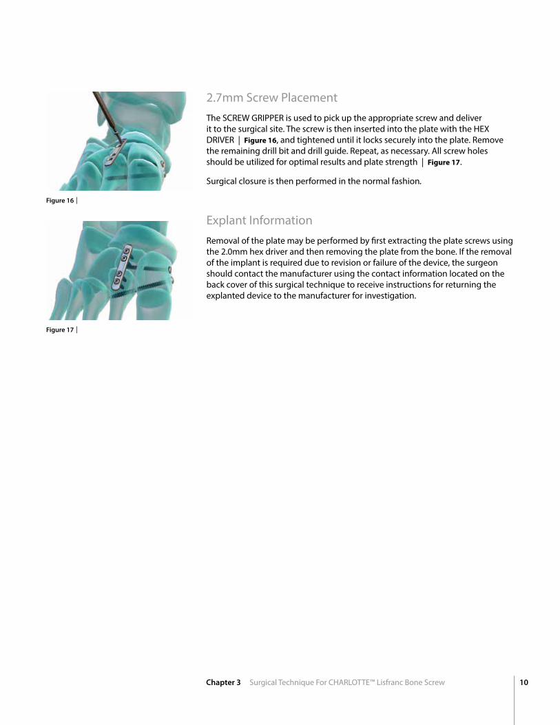
2.7mm Screw PlacementThe SCREW GRIPPER is used to pick up the appropriate screw and deliver it to the surgical site. The screw is then inserted into the plate with the HEX DRIVER | Figure 16, and tightened until it locks securely into the plate. Remove the remaining drill bit and drill guide. Repeat, as necessary. All screw holes should be utilized for optimal results and plate strength | Figure 17.
Surgical closure is then performed in the normal fashion.
Explant InformationRemoval of the plate may be performed by first extracting the plate screws using the 2.0mm hex driver and then removing the plate from the bone. If the removal of the implant is required due to revision or failure of the device, the surgeon should contact the manufacturer using the contact information located on the back cover of this surgical technique to receive instructions for returning the explanted device to the manufacturer for investigation.
Figure 17 |
Figure 16 |

11
Ap
pen
dix
Ordering InformationCHARLOTTE™ Lisfranc Reconstruction System
CHARLOTTE™ Lisfranc Reconstruction System
3.7mm CHARLOTTE™ Lisfranc Screw
Part No. Description Length (mm)
43503720 LISFRANC SCREW 3.7 X 20MM 20
43503722 LISFRANC SCREW 3.7 X 22MM 22
43503724 LISFRANC SCREW 3.7 X 24MM 24
43503726 LISFRANC SCREW 3.7 X 26MM 26
43503728 LISFRANC SCREW 3.7 X 28MM 28 43503730 LISFRANC SCREW 3.7 X 30MM 30
43503732 LISFRANC SCREW 3.7 X 32MM 32
43503734 LISFRANC SCREW 3.7 X 34MM 34 43503736 LISFRANC SCREW 3.7 X 36MM 36 43503738 LISFRANC SCREW 3.7 X 38MM 38
43503740 LISFRANC SCREW 3.7 X 40MM 40
43503742 LISFRANC SCREW 3.7 X 42MM 42
43503744 LISFRANC SCREW 3.7 X 44MM 44
43503746 LISFRANC SCREW 3.7 X 46MM 46
43503748 LISFRANC SCREW 3.7 X 48MM 48
43503750 LISFRANC SCREW 3.7 X 50MM 50
4.5mm CHARLOTTE™ Lisfranc Screw
Part No. Description Length (mm)
43504530 LISFRANC SCREW 4.5 X 30MM 30
43504532 LISFRANC SCREW 4.5 X 32MM 32
43504534 LISFRANC SCREW 4.5 X 34MM 34
43504536 LISFRANC SCREW 4.5 X 36MM 36
43504538 LISFRANC SCREW 4.5 X 38MM 38
43504540 LISFRANC SCREW 4.5 X 40MM 40
43504542 LISFRANC SCREW 4.5 X 42MM 42
43504544 LISFRANC SCREW 4.5 X 44MM 44
43504546 LISFRANC SCREW 4.5 X 46MM 46
43504548 LISFRANC SCREW 4.5 X 48MM 48
43504550 LISFRANC SCREW 4.5 X 50MM 50
Washers
Part No. Description
43500045 LISFRANC WASHER
CHARLOTTE™ LISFRANC SCREW SYSTEM

12CHARLOTTE™ Lisfranc Reconstruction System
CHARLOTTE™ Lisfranc Bridge Plates
Part No. Description
43500022 LISFRANC PLATE – 4-HOLES
43500023 LISFRANC PLATE – 5-HOLES
43500024 LISFRANC PLATE – 6-HOLES
43500009 LISFRANC PLATE – 9-HOLES
CHARLOTTE™ Lisfranc Plate 2.7mm Locking Screws
Part No. Description Length (mm)
40122712 LOCKING SCREW 2.7MM X 12MM 12
40122714 LOCKING SCREW 2.7MM X 14MM 14
40122716 LOCKING SCREW 2.7MM X 16MM 16
40122718 LOCKING SCREW 2.7MM X 18MM 18
40122720 LOCKING SCREW 2.7MM X 20MM 20 40122722 LOCKING SCREW 2.7MM X 22MM 22
40122724 LOCKING SCREW 2.7MM X 24MM 24
40122726 LOCKING SCREW 2.7MM X 26MM 26
40122728 LOCKING SCREW 2.7MM X 28MM 28
40122730 LOCKING SCREW 2.7MM X 30MM 30
CHARLOTTE™ Lisfranc Plate 2.7mm Non-Locking Screws
Part No. Description Length (mm)
41122712 NON-LOCKING SCREW 2.7MM X 12MM 12
41122714 NON-LOCKING SCREW 2.7MM X 14MM 14
41122716 NON-LOCKING SCREW 2.7MM X 16MM 16
41122718 NON-LOCKING SCREW 2.7MM X 18MM 18
41122720 NON-LOCKING SCREW 2.7MM X 20MM 20
41122722 NON-LOCKING SCREW 2.7MM X 22MM 22
41122724 NON-LOCKING SCREW 2.7MM X 24MM 24
41122726 NON-LOCKING SCREW 2.7MM X 26MM 26 41122728 NON-LOCKING SCREW 2.7MM X 28MM 28
41122730 NON-LOCKING SCREW 2.7MM X 30MM 30
CHARLOTTE™ Lisfranc BRIDGE PLATING SYSTEM

1023 Cherry Road Memphis, TN 38117 800 238 7117 901 867 9971 www.wright.com
62 Quai Charles de Gaulle69006 Lyon France+33 (0)4 72 84 10 30 www.tornier.com
18 Amor WayLetchworth Garden CityHertfordshire SG6 1UGUnited Kingdom+44 (0)845 833 4435
™ and ® denote Trademarks and Registered Trademarks of Wright Medical Group N.V. or its affiliates.©2016 Wright Medical Group N.V. or its affiliates. All Rights Reserved.
009925B 16-Sept-2016