Charged Particle Environment for NGST: L2 Plasma ... Particle Environment for NGST: L2 Plasma...
12
FINALI_RAFF ' 24March2000 Charged Particle Environment for NGST: L2 Plasma Environment Statistics Joseph I. Minow *a, William C. BlackwelP, Linda F. Neergaard a, Steven W. Evans b, Donna M. Hardage c, and Jerry K. Owens b "_Sverdrup Technology, Inc., Marshall Space Flight Center Group, Huntsville, AL 35806 bED44/Environments Group, NASA/Marshall Space Flight Center, Huntsville, AL 35812 CED03/Engineering Technology Development Office, NASA/MSFC, Huntsville, AL 35812 Abstract The plasma environment encountered by the Next Generation Space Telescope satellite in a halo orbit about L2 can include the Earth's magnetotail and magnetosheath in addition to the solar wind depending on the orbital radius chosen for the mission. Analysis of plasma environment impacts on the satellite requires knowledge of the average and extreme plasma characteristics to assess the magnitude of spacecraft charging and materials degradation expected for the mission lifetime. This report describes the analysis of plasma data from instruments onboard the IMP 8 and Geotail spacecraft used to produce the plasma database for the LRAD engineering-level phenomenology code developed to provide the NGST L2 environment definition. Keywords: NGST, L2, plasma, environment, modeling, magnetosheath, solar wind, magnetotail 1. Introduction The proposed orbit for the Next Generation Space Telescope (NGST) spacecraft is a halo orbit about the second Lagrange point, L2, approximately 236 Earth radii (Re) from the Earth in the anti-solar direction where the spacecraft will encounter the solar wind and the Earth's magnetosheath in addition to the deep tail regions of the magnetosphere (see Figure la). Deep tail plasma regimes are highly variable in both space and time. Assessment of the deep tail (X_sE < -100 RE) plasma conditions for possible impacts on the NGST spacecraft requires consideration of the variability in the orientation and dimensions of the plasma regimes as well as the statistics of plasma characteristic variations within each regime. Time scales for solar wind variations and magnetospheric response is on the order of tens of minutes, short compared to the typical six month period of a halo orbit. Much of the variability in the plasma environments encountered by the NGST spacecraft will therefore be the result of different plasma regimes moving past a spacecraft that may be treated as stationary relative to the dynamic variations in the orientation and dimension of the deep tail. Computation of particle flux within individual plasma regions and fluence for complete halo orbits in such a dynamic environment are aided by the development of a model to provide a framework for incorporating statistical variations in plasma parameters and fluctuations in magnetotail structure and position due to time dependent variations in the solar wind. The L2 radiation model (LRAD), an engineering-level plasma phenomenology code, was developed to provide estimates of the L2 plasma environment for satellites in halo orbits about L2 [1]. This report provides an overview to the satellite records of solar wind, magnetosheath, and magnetotail plasma data and the analysis used to produce the statistics of the plasma environment for the NGST environment definition. Results from the analysis of the data pertinent to the LRAD code are discussed since the plasma data used to derive the statistics are incorporated into the database for the LRAD model. Finally, we present two examples of applications of the plasma analysis to spacecraft environment interactions--spacecraft charging and sputtering--to demonstrate impacts of the plasma environments on the design of the NGST satellite. *Correspondence: Email: [email protected] .iv"Telephone: 256 544 2850; Fax: 256 544 0242 https://ntrs.nasa.gov/search.jsp?R=20000032965 2018-07-09T13:52:18+00:00Z
Transcript of Charged Particle Environment for NGST: L2 Plasma ... Particle Environment for NGST: L2 Plasma...
FINALI_RAFF' 24March2000
Charged Particle Environment for NGST: L2 Plasma EnvironmentStatistics
Joseph I. Minow *a, William C. BlackwelP, Linda F. Neergaard a, Steven W. Evans b, Donna M.
Hardage c, and Jerry K. Owens b
"_Sverdrup Technology, Inc., Marshall Space Flight Center Group, Huntsville, AL 35806
bED44/Environments Group, NASA/Marshall Space Flight Center, Huntsville, AL 35812
CED03/Engineering Technology Development Office, NASA/MSFC, Huntsville, AL 35812
Abstract
The plasma environment encountered by the Next Generation Space Telescope satellite in a halo orbit about L2 can include
the Earth's magnetotail and magnetosheath in addition to the solar wind depending on the orbital radius chosen for themission. Analysis of plasma environment impacts on the satellite requires knowledge of the average and extreme plasma
characteristics to assess the magnitude of spacecraft charging and materials degradation expected for the mission lifetime.This report describes the analysis of plasma data from instruments onboard the IMP 8 and Geotail spacecraft used to produce
the plasma database for the LRAD engineering-level phenomenology code developed to provide the NGST L2 environmentdefinition.
Keywords: NGST, L2, plasma, environment, modeling, magnetosheath, solar wind, magnetotail
1. Introduction
The proposed orbit for the Next Generation Space Telescope (NGST) spacecraft is a halo orbit about the second Lagrange
point, L2, approximately 236 Earth radii (Re) from the Earth in the anti-solar direction where the spacecraft will encounterthe solar wind and the Earth's magnetosheath in addition to the deep tail regions of the magnetosphere (see Figure la). Deep
tail plasma regimes are highly variable in both space and time. Assessment of the deep tail (X_sE < -100 RE) plasmaconditions for possible impacts on the NGST spacecraft requires consideration of the variability in the orientation anddimensions of the plasma regimes as well as the statistics of plasma characteristic variations within each regime. Time scales
for solar wind variations and magnetospheric response is on the order of tens of minutes, short compared to the typical sixmonth period of a halo orbit. Much of the variability in the plasma environments encountered by the NGST spacecraft will
therefore be the result of different plasma regimes moving past a spacecraft that may be treated as stationary relative to thedynamic variations in the orientation and dimension of the deep tail. Computation of particle flux within individual plasmaregions and fluence for complete halo orbits in such a dynamic environment are aided by the development of a model to
provide a framework for incorporating statistical variations in plasma parameters and fluctuations in magnetotail structureand position due to time dependent variations in the solar wind.
The L2 radiation model (LRAD), an engineering-level plasma phenomenology code, was developed to provide estimates of
the L2 plasma environment for satellites in halo orbits about L2 [1]. This report provides an overview to the satellite recordsof solar wind, magnetosheath, and magnetotail plasma data and the analysis used to produce the statistics of the plasma
environment for the NGST environment definition. Results from the analysis of the data pertinent to the LRAD code arediscussed since the plasma data used to derive the statistics are incorporated into the database for the LRAD model. Finally,
we present two examples of applications of the plasma analysis to spacecraft environment interactions--spacecraft chargingand sputtering--to demonstrate impacts of the plasma environments on the design of the NGST satellite.
*Correspondence: Email: [email protected] .iv"Telephone: 256 544 2850; Fax: 256 544 0242
https://ntrs.nasa.gov/search.jsp?R=20000032965 2018-07-09T13:52:18+00:00Z

• , ¢
FINAL DRAFT • 24 March 2000
rY
-225
-150
-75
75
150
...... 4. ...................
L1
S_lar Wind
q225 ........ i .... _u___,_,,_ ,_ L,_t..... _L,_,_,_,__ t_,_,__,__
300 200 100 0 --100 --200 --.SQO
X_ (R_)
a) b)
SW
Plasma
Figure 1. Magnetotail Plasma Environments. A schematic of the Earth-Moon system projected onto the ecliptic (GSE X-Y) plane showing the locations of the first and second Lagrange points, L1 and L2, relative to the Earth and lunar orbit. Asample halo orbit is indicated about L2 to demonstrate the magnitude of the orbital amplitudes relative to the dimensions of themagnetotail and magnetosheath at L2 distances. The cross section of the magnetotail in the GSE Y-Z plane indicates themagnetotail plasma regimes. Labels indicate the solar wind (SW), magnetosheath (MS), boundary layer (BL), lobe (LB),plasma sheet (PS), low latitude boundary layer (LLBL), central plasma sheet (CPS), and plasma sheet boundary layer (PSBL)(magnetotail plasma regime figure adapted from [2]).
2. Observations of Magnetotail Plasma Environments
The immense size of a typical L2 halo orbit relative to the dimensions of the magnetosphere is illustrated in Figure la.Satellites in a variety of halo orbits about L2 with different orbital amplitudes will spend an appreciable fraction of time in
plasma regimes associated with the Earth's magnetosphere as well as the solar wind (c.f., [i]). Plasma regimes at deep taildistances fall into one of three main categories: the unperturbed solar wind, the magnetosheath, and the magnetotail.Spacecraft at downtail distances beyond approximately 50 RE may be located in any of these plasma regimes at any time due
to the tremendous variability in the dimension and orientation of the magnetotail at large distances from the Earth [i, 2].
A cross section in the Geocentric Solar Ecliptic (GSE) Y-Z plane illustrating the dominant plasma regimes identified over theyears during satellite exploration of the magnetotail at various distances from the Earth is given in Figure lb [2]. The solarwind, magnetosheath, boundary layer, lobe, and plasma sheet regions are clearly distinguishable in the deep tail although
many of the subdivisions identified in the magnetotail nearer the Earth are not so apparent in plasma records obtained at L2distances [2,3].
Relatively few spacecraft have sampled the plasma in the deep magnetotail. The two primary sources to date for deep tailplasma magnetic field records are the ISEE-3 mission during the late 1970's and early 1980's [4,5,6,7] and the more recent
Geotaii mission [2,3,8,9]. Geotaii sampled the distant tail over a range of downtail distances from XGSE = --50 Re to -209 Reover the period from late 1992 through the end of 1994.
Statistics for plasma regimes within the magnetotail and the magnetosheath incorporated into LRAD are obtained from
records obtained by the University of Iowa Comprehensive Plasma Instrument (CPI) onboard the Geotail satellite. Plasmamoments (number density, temperature, and flow velocities) from January through June 1993 were available for analysis.An example of this data is given in Figure 2 where all of the data from the six month period is plotted as a function of

FINALDrRAFT' 24March2000
Geotail/CPIlo B
danuar-_y - June 1995
_,-,-10 7 _ ' • . . ., • V" :" " - ; ,i 'i_ . .'.'.,_ .... I " "!,",,., - _ " _ _i.,_.,
_ _4 l- i_ t,4! , b/'_'_'''_ ....
.._o__:__ im_,_,L.,: .i:_._ll_,i..._i,: ..,,_.,i,,,,._,.., ,, .....-_;_. ....... ""10 r li liIII!l-.iIlti,_llflHl.iltliilil_liJ-_':¢i:-"._ :' " sMn_;; _"_:__
1 5-. ' . '" • " . *" "'- " . ..E.' *
_ _.oo r i.' ' f' _ ' ' .."..f,:l "_ I,..
'_" 400-- , - ": _: ;_-': ,'it; ] :'
o- '' ' " "'7!,--_00 :,: , . :' ,-: .
"_ 4oo>>'_ o
•_, -400-800
_" 4O0N'_>E o
-_._-.-4oo--BOO
1
1
__.-1
1
.
1
1
i
__ . w
:._ • -. ' +.... _diil""-: _,.,..' "+i;+lf ".,"
--2130 -150 - 100 --_SO
×_E (R_)
Figure 2. Survey of Magnetotail and Magnetosheath Plasma Characteristics. The data is from the University ofIowa/CPl instrument onboard the Geotail satellite for the first 180 days in 1993. Values for all GSE Y and Z distances areplotted on the same axis. Data gaps are due to the sparse sampling of deep tail plasma regimes during the four deep tail passesrepresented in the data set.
distance along the Sun-Earth line. Flow velocities and densities refer to the ions but both ion and electron temperatures were
available in the data set. Four individual orbits through the deep tail are included in the data set providing samples of deeptail plasma environments over a range of distances from 50 RE downstream of the Earth to a maximum distance of nearly 209Re downstream of the Earth. Geotail plasma data is not available from L2 but the records shown in Figure 2 exhibit no
significant trends in the plasma moments as a function of downtaiI distance for XGSE < -100 Re. Previous studies of themagnetotail have shown that for X6SE < -50 RE the source of plasma encountered in the magnetotail is solar wind that entered
the magnetosphere either through the dayside polar cusp or locally along the open magnetopause boundary. Magnetotailplasma beyond XOSE = -100 Re is nearly all due to solar wind entering the tail locally [10]. Deep tail plasma moments and
composition therefore should exhibit similar characteristics for a wide range of distances in the magnetotail beyondapproximately X6SE = -100 RE.
Identification of the plasma regimes for the Geotail CPI records is provided by the EPIC (Energetic Particle and IonComposition instrument) Science Team [2,3]. The classification scheme uses the data from CPI in addition to a variety of
other instruments onboard the Geotail spacecraft to classify the Geotail records as belonging to plasma sheet, lobe, boundarylayer, magnetosheath, and solar wind plasma regimes. Adopting the EPIC Science Team plasma regime identifications
facilitated the computation of the statistics for the electron and ion densities, velocities, and temperatures for each of the deeptail plasma regimes.
An alternative data source is required for information on the solar wind because solar wind encounters are not present in the
Geotail data set shown in Figure 2. Solar wind properties presented here are from a number of the Interplanetary MonitoringPlatform (IMP) satellites• The IMP series satellites were placed in near circular, 35 to 40 RE orbits for observations of the
solar wind and magnetosphere. Solar wind plasma characteristic statistics are obtained from data provided by the MITFaraday Cup instrument onboard Interplanetary Monitoring Program (IMP) IMP-8 satellite. Data from an interval starting in

FINALDRAFT. 24March2000 4
1
___,_,_10 6
t
_- 100o_E t0
::_ .
A
_o -200x_
> E -400-600
"J -80O
co 400
>>'_" 0__x: --400"_ -8OO
_o 400N_>E 0
,F --400"-" -800
IMP-8 1995
10 10 20 50 40 50 60 70 80 90 100
Doy Number
Figure 3. Example 1993 IMP-8 Solar Wind Plasma Characteristics. The large data gaps in the data set occur when thesatellite is inside the magnetosheath and magnetosphere. The dominant velocity component, Vx, although variable is alwaysnegative indicating the plasma environment in the solar wind is highly anisotropic.
early November 1973 through the end of December 1998 are included in the analysis, a time period spanning almost three
complete solar cycles. A sample of IMP-8 records is shown in Figure 3.
Plasma populations in all regimes are quasi-neutral such that the electron and net ion densities are equal, a useful plasma
property since electron densities are not available in the IMP-8 records. Electron densities are estimated from the quasi-neutral condition
N_ = __ nkN k (1)
where nk is the charge state of the kth ion species of density Nk in a quasi-neutral plasma. It is generally sufficient to include
only hydrogen and helium ions in the sum at L2 distances due to the relatively low abundance of heavy ions in the solar wind
and distant magnetotail.
Electron and ion temperatures in the tables in the following sections are given in multiples of lxl0 _ K to facilitate conversion
to electron volts (eV). Approximate temperatures in electron volts (with an error on the order of 20%) is read directly fromthe tables since the conversion between the units is 11604 K/I eV.
FINALDRAFT° 24March2000 5
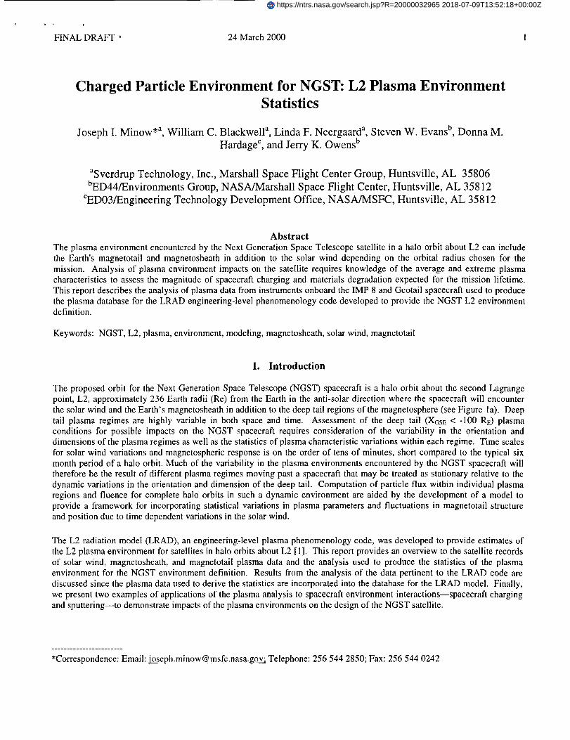
Table 1. Radial Variations in Solar Wind Plasma Characteristics
Plasma density n o_ Rs -21+-°3 [I 1]
Proton temperature Tp oc Rs -°s7 [12]
Electron temperature Te oc R_ °33 [! 2]
Magnetic field [/_ 1o_l/_/(gs-2+ Rs -4 )/2 [12]
Plasma velocity Vsw = constant [ ! 2]
3. Solar Wind Characteristics
Radial variations in plasma number density, temperature, and magnetic field intensity are given in Table 1 where Rs is thedistance from the Sun to the Earth in Astronomical Units (AU). The scale length for variations in solar wind characteristics
are sufficiently large that plasma data obtained from near the Earth are simply adopted for the L2 environment withoutcorrection for radial variations. Adding the 0.01 AU distance from Earth to L2 to the Sun-Earth distance of 1 AU yields L2
densities, temperatures, and magnetic fields less than a few percent different than values determined in the vicinity of theEarth. Formally the near Earth values should be corrected for the distance to L2 but the errors are small compared to the
variations in each of the parameters. No correction is required for solar wind velocity since the magnitude of the flow speed
is nearly constant between 1 and 20 AU [13].
3.1 Solar Wind Plasma Statistics
Table 2 contains statistics of solar wind plasma characteristics using data from the IMP 6, IMP 7 and IMP 8 satellitesobtained over an interval from March 1971 through July 1974 [14]. Results from this study are included here because values
for the electron, proton, and helium temperatures are available in addition to the ratio of helium to proton number densities.Table 3 contains results from an extended set of IMP 8 observations from 1973 through December 1998. The advantage of
the latter data set, while only including proton observations, is the greater coverage over nearly three complete solar cycles inthe time series to more completely explore range of variations in the proton density, temperature, and velocity.
Solar wind electrons are composed of two populations. A core population of high density, low energy electrons dominateswith a minor density contribution due to a halo population of high temperature electrons. Density of the core population is
typically ten times that of the halo population but only one tenth the temperature [13]. Two component plasma momentsobtained from fits to a bi-Maxwellian velocity distribution is required to characterize both populations but this information isnot available in the IMP 8 plasma moment records where numerical integrations of the velocity distribution were used to
obtain the moments (c.f., [1 ]). The solar wind electron statistics presented here will therefore apply primarily to the dominant
core population.
Species composition is shown in Table 4 for average solar wind, low speed solar wind, high speed solar wind, and a coronalmass ejection driver gas (a transient solar disturbance) are given as well to demonstrate the variability of ion composition fordifferent solar wind conditions. Hydrogen ions dominate in all cases, with helium the most common minor species. Ions
heavier than helium are present in the solar wind but represent a negligible contribution to the total solar wind mass. Thissame composition will also apply throughout the magnetosheath and into the magnetotail at L2 distances because the plasma
source for the magnetotail beyond approximately 100 Re from the Earth is primarily the solar wind [ 10].
It should be noted that use of the values in Tables 1 through 3 are complicated by the requirement that correlations between
the individual values must be considered to obtain meaningful results for extreme values of the electron and proton flux. For
example, solar wind densities and speeds are generally anti-correlated, with the greatest densities occurring during periods oflow speed flows and the smaller densities occurring in high speed solar wind flows. Examples of the anti-correlation are
FINALDRAFT" 24March2000
a)
b)
,4Ok-
j3_
Ur'
O
.d2
121_
O_ " " '' " " "
-2
-4
0 20 4-0 50 80100
Density (#/cm s)
0 C .......
-1
-2
-3
-4
0 20 40 60 80100
Density (#/cm 3)
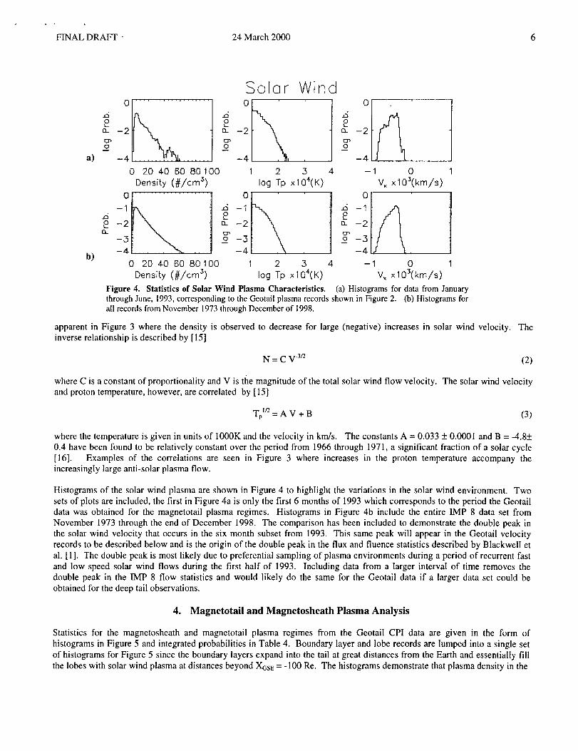
Figure 4.
_d£
[3..
El',
O
.,5£n
Solor Wind
-2
-4
1 2 3
log Tp xlO4(K)
-1
-2
-3
-4
1 2 3
log Tp xlO4(k)
4
Statistics of Solar Wind Plasma Characteristics.
0
£ca. --2
-4 , .....
-1 0
V_ x I03(km/s)
0
,4 -t
o_ --2
0
V_ x I03(krn/s)
(a) Histograms for data from Januarythrough June, 1993, corresponding to the Geotail plasma records shown in Figure 2. (b) Histograms forall records from November 1973 through December of 1998.
apparent in Figure 3 where the density is observed to decrease for large (negative) increases in solar wind velocity.inverse relationship is described by [15]
The
N = C V -3r2 (2)
where C is a constant of proportionality and V is the magnitude of the total solar wind flow velocity. The solar wind velocityand proton temperature, however, are correlated by [ 15]
Tp I/2 = A V + B (3)
where the temperature is given in units of 1000K and the velocity in km/s. The constants A = 0.033 + 0.0001 and B = -4.8+0.4 have been found to be relatively constant over the period from 1966 through 1971, a significant fraction of a solar cycle
[16]. Examples of the correlations are seen in Figure 3 where increases in the proton temperature accompany theincreasingly large anti-solar plasma flow.
Histograms of the solar wind plasma are shown in Figure 4 to highlight the variations in the solar wind environment. Twosets of plots are included, the first in Figure 4a is only the first 6 months of 1993 which corresponds to the period the Geotail
data was obtained for the magnetotail plasma regimes. Histograms in Figure 4b include the entire IMP 8 data set fromNovember 1973 through the end of December 1998. The comparison has been included to demonstrate the double peak in
the solar wind velocity that occurs in the six month subset from 1993. This same peak will appear in the Geotail velocityrecords to be described below and is the origin of the double peak in the flux and fluence statistics described by Blackwell etal. [1]. The double peak is most likely due to preferential sampling of plasma environments during a period of recurrent fast
and low speed solar wind flows during the first half of 1993. Including data from a larger interval of time removes thedouble peak in the IMP 8 flow statistics and would likely do the same for the Geotail data if a larger data set could be
obtained for the deep tail observations.
4. Magnetotail and Magnetosheath Plasma Analysis
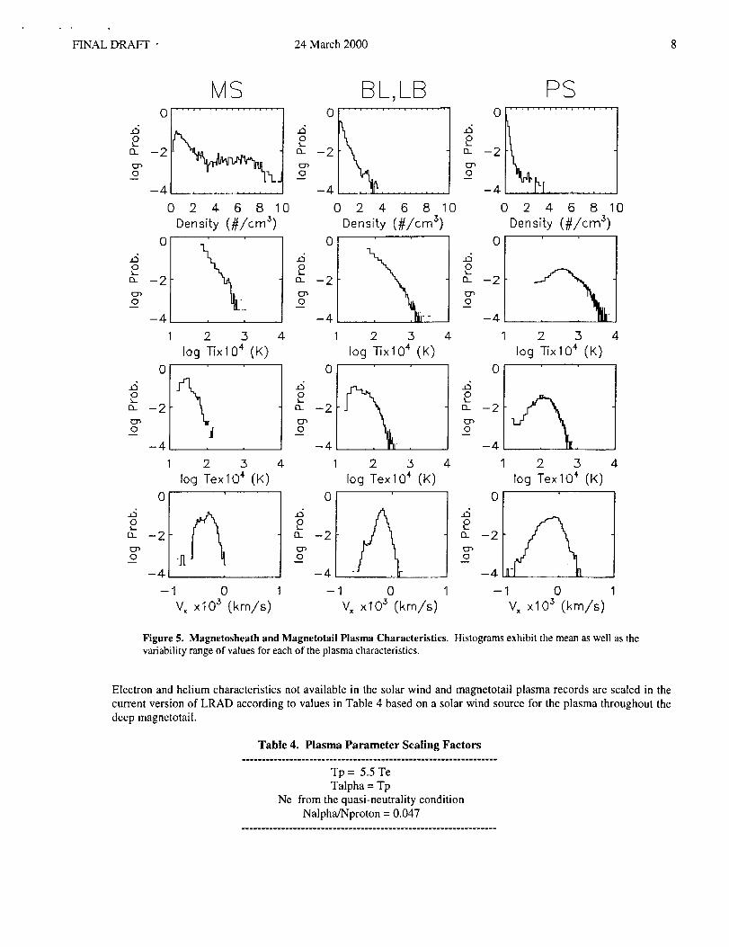
Statistics for the magnetosheath and magnetotail plasma regimes from the Geotail CPI data are given in the form of
histograms in Figure 5 and integrated probabilities in Table 4. Boundary layer and lobe records are lumped into a single set
of histograms for Figure 5 since the boundary layers expand into the tail at great distances from the Earth and essentially fillthe lobes with solar wind plasma at distances beyond XGSE = -100 Re. The histograms demonstrate that plasma density in the
FINALDRAFT 24March2000
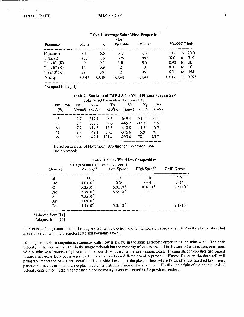
N(#/cm3) 8.7 6.6 5.0 6.9 3.0 to 20.0
V (knds) 468 116 375 442 320 to 710
Tp xl04(K) 12 9.1 5.0 9.5 0.98 to 30Te xl04(K) 14 3.9 12 13 8.9 to 20
T_ xl04(K) 58 50 12 45 6.0 to 154
No./Np 0.047 0.019 0.048 0.047 0.017 to 0.078
"Adapted from [ 14]
Table 2. Statistics of IMP 8 Solar Wind Plasma Parameters a
Solar Wind Parameters (Protons Only)
Cum. Prob. Ni Vsw T_ Vx Vy Vz(%) (#/cm3) (km/s) xl0 (K) (knds) (km/s) (km/s)
....................................................................................
5 2.7 317.4 3.5 -649.4 -34.0 -31.3
33 5.4 380.3 9.0 -465.2 -13.1 2.950 7.2 414.6 13.5 -410.8 -4.5 17.267 9.8 469.4 20.5 -376.6 5.9 26.1
99 39.5 742.4 101.4 -290.4 78.1 85.7
"Based on analysis of November 1973 through December 1988IMP 8 records.
Table 3. Solar Wind Ion Composition
Composition (relative to hydrogen)Element Average" Low Speed b High Speed b CME Driver b
.......................................................................................................................
H 1.0 1.0 1.0 1.0He 4.0x 10.2 0.04 0.04 >. 15O 5.2x 10.4 5.0x 10 -4 8.0x 10 .4 7.5 x 10 .4
Ne 7.5x 10.5 8.5x 10 -s ......Si 7.5x10 -5Ar 3.0x10 6
Fe 5.3x10 5 5.0x10 -s --- 9.1x10 -_.......................................................................................................................
aAdapted from [ ! 4]bAdapted from [ 17]
magnetosheath is greater than in the magnetotail, while electron and ion temperatures are the greatest in the plasma sheet butare relatively low in the magnetosheath and boundary layers.
Although variable in magnitude, magnetosheath flow is always in the same anti-solar direction as the solar wind. The peak
velocity in the lobe is less than in the magnetosheath but the majority of values are still in the anti-solar direction, consistentwith a solar wind source of plasma for the boundary layers in the deep magnetotait. Plasma sheet velocities are biased
towards anti-solar flow but a significant number of earthward flows are also present. Plasma fluxes in the deep tail willprimarily impact the NGST spacecraft on the sunshield except in the plasma sheet where flows of a few hundred kilometers
per second may occasionally drive plasma into the instrument side of the spacecraft. Finally, the origin of the double peakedvelocity distribution in the magnetosheath and boundary layers was noted in the previous section.
FINAL DRAFT • 24 March 2000 8
.dOk..
£1-
O
,4Ok_
O
,4Ok_
[2_
ur_O
,4Ok_
D_
O
0
-2
-4
MS
-2
0
Density (#/cm s)0
-4
1
0
-2
-4
2 4- 6 8 10
2 3
log -1-ixlO4 (K)
-2
-4
1
4
1 2 3 4
log TexlO _ (K)
`40
k
Y
`40k_
13-
0
,40
CL
0
,40k_
13..
0
0
-2
-4-
0
-2
-4
1
0
-2
-4
1
0
-2
BL,LB
0 2 4 6 8 10
Density (#/cm 3)
2 3 4
log TixlO 4 (K)
2 3
log Tex 104 (t<)
-4
-1 0 1 -1V, xlO 3 (kin/s) V,
0xlO 3 (km/s)
,40k_Q_
£T,0
.60k_
Q_
0
,40
£1-
0
0
-2
-4
-2
0
0
-4
1
PS
0
-2
2 4 6 8 10
Density (#/cm 3
2 .3 4
log q-ix 104 (K)
4 1 2 3 4
log Tex 10 "_ (K)
`40
13_
Er',0
0xlO 3 (kin/s)
0
-2
-4
1 -1 1
Vx
Figure 5. Magnetosheath and Magnetotail Plasma Characteristics. Histograms exhibit the meanaswell as thevariabilityrange of values foreach of the plasma characteristics.
Electron and helium characteristics not available in the solar wind and magnetotail plasma records are scaled in thecurrent version of LRAD according to values in Table 4 based on a solar wind source for the plasma throughout thedeep magnetotail.
Table 4. Plasma Parameter Scaling Factors...................................... w.w_.w..w..._w.. ..........
Tp = 5.5 TeTalpha = Tp
Ne from the quasi-neutrality conditionNalpha/Nproton = 0.047

FINAL DRAFT - 24 March 2000 9
Table 5. Statistical Variations in Magnetosheath and Magnetotaii Plasma Parameters
Magnetosheath Parameters a
Cumulative Ni Ti Te Vx Vy VzProb. (#/cc) xl04(K) xl04(K) (krn/s) (km/s) (km/s)
............................................................................................
5 0.283 18.6 3.12 -519 -93.6 -52.3
33 0.687 75.5 20.6 -383 -50.0 -15.850 1.006 92.7 31.2 -311 -32.9 -7.21
67 1.645 110. 41.8 -272 -12.1 -0.8899 8.684 461. 111. -112 75.1 35.3
Boundary Layer Parameters _Cumulative Ni Ti Te Vx Vy Vz
Prob. (#/cc) x104 (K) x104 (K) (km/s) (km/s) (km/s)............................................................................................
5 0.108 30.9 6.03 -297. -61.2 -68.833 0.235 90.3 39.8 -199. -18.8 -23.6
50 0.316 114. 60.7 -167. -5.67 -12.067 0.440 165. 84.9 - 139. 6.87 - 1.9099 2.286 1220. 272. 2.49 74.4 58.7
Lobe Parameters a
Cumulative Ni Ti Te Vx Vy Vz
Prob. (#/cc) x104 (K) x104 (K) (km/s) (km/s) (km/s)..............................................................................................
5 0.010 93.7 75.2 -194. -119. -202.
33 0.069 405. 151. -50.5 -23.0 -79.350 0.107 627. 205. -24.0 5.62 -55.4
67 0.166 1180. 303. 11.5 33.6 -28.599 0.620 5880. 1650. 330. 208. 124.
Plasma Sheet Parameters _
Cumulative Ni Ti Te Vx Vy VzProb. (#/cc) x104 (K) x104 (K) (km/s) (km/s) (km/s)
...............................................................................................
5 0.015 185. 60.0 -378. -104. -148.33 0.096 472. 130. -134. -25.4 -58.0
50 0.146 708. 169. -62.0 -4.87 -36.067 0.196 1100. 228. -10.1 14.7 -17.4
99 1.361 4740. 753. 308. 154. 81.0
_Based on analysis of Geotail Comprehensive Plasma Instrument records.

FINALDRAFT• 24March2000 ]0
Surface Pofenfial
sun shade_>0
felescope--_ assembly/
_<0
Volfs
8
6
4
Z
E+O0
-Z
-4
-6
-8
-10!
-lz!i
-14 1
-16 !
-20 I
-22
-24.
-Z6
-28
Figure 6. Example Charging Analysis. The hypothetical spacecraft shares many of the characteristics of the proposedNGST architectures. Orientation of the spacecraft is fixed with the sunshade illuminated by the sun and the instrumentpackage/telescope structure in the shadow of the sunshade. The potential over most of the sunshade is positive while that ofthe instrument package/telescope structure charges to a negative potential.
5. Example of Plasma Effects
Spacecraft charging and surface degradation due to ion sputtering are two examples of plasma effects on a spacecraft. The
origin of spacecraft charging differential collection of currents from the ambient plasma environment which balances theoutgoing photoelectron, secondary electron, and secondary ion currents produced when charged particles collide with the
spacecraft surface. Sputtering is a loss of atoms from the outer surface of the spacecraft primarily due to ion bombardment.
6.1 Spacecraft Charging
A simple order of magnitude estimate of the equilibrium potential expected for a spacecraft is obtained from the "rule of
thumb" that a spacecraft structure in darkness will charge to a negative potential that is a few times the electron temperaturesince there is not outgoing photoelectron current to balance incident electron current from the ambient plasma environment
[ 18]. Applying the "rule of thumb" to electron temperatures given in the tables above for a range of temperature of 50 eV to200 eV suggest potentials on the order of-100 volts to -400 volts. Potentials as great as -1000 to -3000 volts are predictedusing the "rule of thumb" in plasma regimes where the extreme electron temperatures may reach 500-1500 eV (c.f., the lobe
and plasmsheet electron temperatures in Table 5).
The photoelectron currents leaving the sunlit surface of a spacecraft are typically much greater than the electron current to thesurface from the plasma environment in the low density plasma regimes found outside of the Earth's inner magnetosphere.
Illuminated spacecraft surfaces under these conditions will typically charge to positive potentials. Pederson et al. [19]obtained the empirical relationship
(volts) = 9Ne[cm 3] -o44 (4)
for the spacecraft potential cp if the external plasma density is between 0.0001 cm 3 and I0 cm -3. These simple scaling laws
suggest the sunlit surface of the NGST sunshield will charge to potentials of approximately positive tens of volts. The
greatest positive potentials are expected when the plasma density is the least, in the plasma sheet and lobes, and may reachvalues of 50-60 volts.
Output from a NASCAP GEO charging analysis in Figure 6 shows surface potentials for a candidate spacecraft with anarchitecture similar to that proposed for NGST. This model is not meant to suffice for a complete charging analysis for the
NGST design since the exact material properties, spacecraft configurations, and the final orbit design for the mission have

FINALDRAFT 24March2000 I1
Table 6. Solar Wind Environment for NASCAP GEO Calculation......................................................................................
Ambient Electrons Ambient Ions (protons)Ne = 8.7 #/cm 3 Np = 8.0 #/cm 3
Te= 10eV Tp= 2.5eV......................................................................................
yet to be defined. We have simply adopted an architecture that places an instrument package in the shadow of a sunshade todemonstrate that a standard charging model confirms the predictions from the "rule of thumb" and scaling laws for the
spacecraft surface potentials. The conditions used for the environment in the NASCAP calculation are listed in Table 9.
Although NASCAP GEO is known to underestimate surface potentials in sunlight due to a limited solar photon spectrumincluded in the model when used in low density plasma environments [I. Katz, personal communication, 2000], the results in
Figure 6 are consistent with the simple scaling laws. Using the electron density value in Table 6, Equation 4 predicts asurface potential of approximately +3.5 volts for the surface of the illuminated sunshade while the NASCAP result in Figure
6 exhibits a potential between +6 and +8 volts over most of the sunshade surface. Applying the "rule of thumb" to the 10 eVelectron temperature used in the NASCAP analysis predicts potentials of-20 to -30 for the telescope structure in darkness,
consistent with the NASCAP result of -14 volts to -20 volts. A more sophisticated analysis of spacecraft charging will
require material properties and details of the satellite architecture since conductivity of the surface materials and grounding ofthe various components is a major factor in determing the nature of the surface potentials.
6.2 Ion Sputtering
Ions will remove material from the spacecraft surface through an ablation process primarily in the solar wind andmagnetosheath where the bulk flow velocity imparts energies to ions of a few keV. Ion sputtering has been shown to be animportant process for removing contaminants on Langmiur probes in the solar wind [20] and may impact thin materials and
coatings used in the construction of NGST. Light ion sputtering yields for 1 keV projectiles are typically 10 .2 for hydrogen,10 l for helium, and 1 for oxygen on metals [21].
7. Summary
Plasma records from the IMP-8 and Geotail spacecraft have provided the basis of the database used in the LRAD deep tail
plasma environment model. Statistics of the deep tail environment obtained from these records are useful in estimatingplasma impacts on spacecraft to be placed in orbits about L2. Examples of plasma interactions with spacecraft surfaces
showed that while not expected to be very serious to the NGST satellite, some areas of concern will require further analysisand laboratory testing to assure the reliable operation of the spacecraft.
Acknowledgements
Comprehensive Plasma Instrument data from the Geotail spacecraft was generously provided by Dr. Louis A. Frank and Dr.
William R. Paterson, University of Iowa. The Geotaii EPIC Science Team provided the plasma regime identifications usedto classify the University of Iowa records. IMP-8 solar wind plasma records from the MIT instrument were obtained fromthe NSSDC data archives. Dr. Alan J. Lazarus and Dr. Karolen Paularenus, MIT, are the Principle Investigators. We also
wish to acknowledge the support of Janet Barth, Gordon Banks, and Christina Gorsky of NASA/GSFC for obtaining a
number of the data sets (courtesy of the National Space Science Data Center). This work was supported in part by NASAContract NAS8-80436 to Sverdrup Technology, Inc.
References
1. Blackwell et ai., Charged particle environment for NGST: Model development, this volume, 2000.2. Eastman, T.E., Christon, S.P., T. Doke, L.A. Frank, G. Gloeckler, H. Kojima, S. Kokubun, A.T.Y. Lui,
H. Matsumoto, R.W. McEntire, T. Mukai, S.R. Nylund, W.R. Paterson, E.C. Roelof, Y. Saito,T. Sotirelis, K. Tsuruda, D.J. Williams, and T. Yamamoto, Magnetospheric plasma regimes identified
using GeotaiI meausrements 2. Regime identification and distant tail variability, J. Geophys. Res.,103, 23521 - 23542, 1998.
3. Christon, S.P., T.E. Eastman, T. Doke, L.A. Frank, G. Gloeckler, H. Kojima, S. Kokubun, A.T.Y. Lui,

FINALDRAF'r- 24March2000 12
H.Matsumoto,R.W.McEntire,T.Mukai,S.R.Nylund,W.R.Paterson,E.C.Roelof,Y.Saito,T.Sotirelis,K.Tsuruda,D.J.Williams,andT.Yamamoto,MagnetosphericplasmaregimesidentifiedusingGeotailmeausrements2. Statistics,spatialdistribution,andgeomagneticdependence,J. Geophys. Res., 103, 23521 -23542, 1998.
4. Bame, S.J., et. al., Plasma regimes in the deep geomagnetic tail: ISEE-3, Geophys. Res. Letters, 10, 912 - 915, 1983.
5. Cowley, S.W.H., et al., Energetic ion regimes in the deep geomagnetic tail: ISEE-3, Geophys. Res. Lett., 11,275 - 278, 1984.
6. Fairfield, D.H., On the structure of the distant magnetotail: ISEE-3, J. Geophys. Res., 97, 1403 - 1410, 1992.
7. Slavin, J.A., et al., An ISEE 3 study of average and substorm conditions in the distant magnetotail, J. Geophys. Res.,90, 10875- 10895, 1985.
8. Paterson, W.R., and L.A. Frank, Survey of plasma parameters in Earth's distant magnetotail with the Geotail spacecraft,
Geophys. Res. Lett., 21, 2971 - 2974, 1994.9. Maezawa, K., and T. Hori, The distant magnetotail: Its structure, IMF dependence, and thermal properties, in New
Perspectives on the Earth's Magnetotail, AGU Monograph 105, (ed. by A. Nishida, D.N. Baker, andS.W.H. Cowley), American Geophysical Union, Washington, D.C., pp. t - 19, 1998.
10. Baker, D.N., and T.I. Pulkinnen, Large-scale structure of the magnetosphere, in New Perspectives onthe Earth's Magnetotail, AGU Monograph 105, (ed. by A. Nishida, D.N. Baker, and
S.W.H. Cowley), American Geophysical Union, Washington, D.C., pp. 21 - 31, 199811. Belcher, J.W., A.J. Lazarus, R.L. McNutt, Jr., and G.S. Gordon, Solar wind conditions in the outer heliosphere and
the distance to the termination shock, J. Geophys. Res., 98, 2177, 1993.12. Smith, E.J., and A. Barnes, Spatial dependences in the distant solar wind: Pioneers 10 and i I, p. 521 in NASA CP 2280,
Solar Wind5, 1983.
13. Cravens, T.E., Physics of Solar System Plasmas, Cambridge University Press, Atmospheric and SpaceScience Series, 1997.
14. Feldman W.C., J.R. Asbridge, S.J. Bame, and J.T. Gosling, Plasma and MagneticFields from the Sun, in The Solar Output and its Variation, (ed.) Oran R. White, Colorado Associated
University Press, Boulder, 1977.
15. Burlaga, L.F., and K.W. Ogilvie, Heating of the solar wind, Astrophys. J., 159, 659, 1970.16. Burlaga, L.F., and K.W. Ogilvie, Solar wind temperature and speed, J. Geophys. Res., 78, 2028, 1973.17 Geiss, J., and P. Bochsler, Solar wind composition and what we expect to learn from out-of-ecliptic
measurements, in The Sun andthe Heliosphere in Three Dimensions, pp. 173 - 186, (ed.) R.G.Marsden, D. Reidel Pub. Co., 1986.
18 Moore, T.E., C.J. Pollock, and D.T. Young, Kinetic Core Plasma Diagnostics, in Measurement Techniques in SpacePlasmas: Particles, Geophysical Monograph 102, edited by R.B. Pfaff, J.E. Borovsky, and D.T. Young, pp. 105 - 123,
American Geophysical Union, Washington, D.C., 1998.19 Pederson, A., Solar wind and magnetospher plasma diagnostics by spacecraft electrostatic potential meausrements, Ann.
Geophys., 13, 118 - 129, 1995.20 Brace, L.H., Langmuir probe measurements in the ionosphere, in Measurement Techniques in Space
Plasmas: Particles, Geophysical Monograph 102, edited by R.B. Pfaff, J.E. Borovsky, and D.T.
Young, pp. 23 - 35, American Geophysical Union, Washington, D.C., 1998.21. Behrisch, R., (ed.), Sputtering by Particle Bombardment I, Physical Sputtering of Single-Element Solids, Topics in
Applied Physics, Volume 47, Springer-Verlag, 1981.


![Windows Mac OS X [10.8+] - Attasaattasa.com/madcatz/support/pdf/MCB32266-MUG-R2-10... · l2 l1 l2 r2 r2 r1 l2 l1 r1 l1 r2 r1 l2 l1 l2 r2 r1 l1 r2 r1 l2 l1 l2 r2.10.11. fcc id: p25d243710a4512c](https://static.fdocuments.net/doc/165x107/5ba4bf5f09d3f235188bed3d/windows-mac-os-x-108-l2-l1-l2-r2-r2-r1-l2-l1-r1-l1-r2-r1-l2-l1-l2-r2-r1.jpg)