Charcoal Kiln Made 00 Ol So
33
Bulletin 494 February, 1946 A CHARCOAL KILN MADE OF CINDER -CONCRETE BLOCKS A. Richard Olson and Henry W. Hicock (KonttBctkut Agricultural ^Experiment Station
Transcript of Charcoal Kiln Made 00 Ol So

8/12/2019 Charcoal Kiln Made 00 Ol So
http://slidepdf.com/reader/full/charcoal-kiln-made-00-ol-so 1/32
Bulletin 494 February, 1946
A CHARCOAL KILN
MADE OF
CINDER-CONCRETE BLOCKS
A. Richard Olson and Henry W. Hicock
(KonttBctkut
Agricultural ^Experiment Station

8/12/2019 Charcoal Kiln Made 00 Ol So
http://slidepdf.com/reader/full/charcoal-kiln-made-00-ol-so 2/32

8/12/2019 Charcoal Kiln Made 00 Ol So
http://slidepdf.com/reader/full/charcoal-kiln-made-00-ol-so 3/32
Front view of two-cord kiln with the chimney in place and the
chimney stove banked with earth except at the front end.

8/12/2019 Charcoal Kiln Made 00 Ol So
http://slidepdf.com/reader/full/charcoal-kiln-made-00-ol-so 4/32
8/12/2019 Charcoal Kiln Made 00 Ol So
http://slidepdf.com/reader/full/charcoal-kiln-made-00-ol-so 5/32
A CHARCOAL KILN
MADE OF
CINDER -CONCRETE BLOCKS 1
A. Richard Olson and Henry W. Hicock
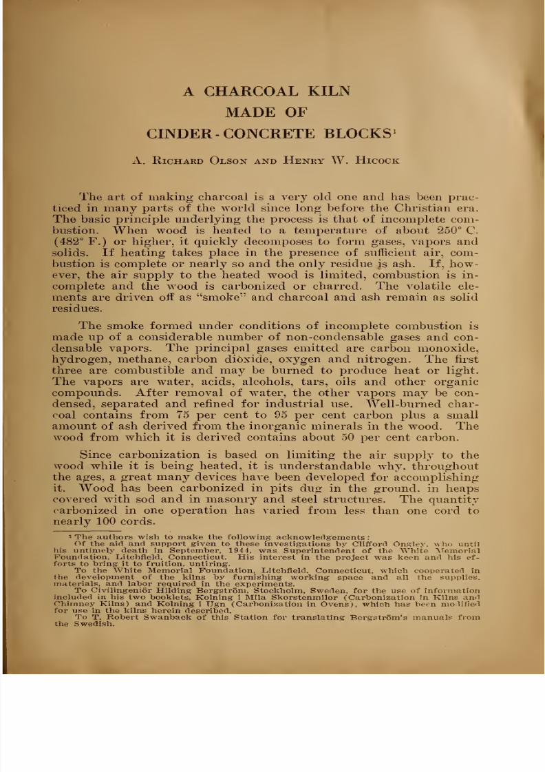
The art of making charcoal is a very old one and has been prac-
ticed in many parts of the world since long before the Christian era.
The basic principle underlying the process is that of incomplete com-bustion. When wood is heated to a temperature of about 250° C.
(482° F.) or higher, it quickly decomposes to form gases, vapors and
solids. If heating takes place in the presence of sufficient air, com-
bustion is complete or nearly so and the only residue is ash. If, how-
ever, the air supply to the heated wood is limited, combustion is in-
complete and the wood is carbonized or charred. The volatile ele-
ments are driven off as smoke and charcoal and ash remain as solid
residues.
The smoke formed under conditions of incomplete combustion ismade up of a considerable number of non-condensable gases and con-
densable vapors. The principal gases emitted are carbon monoxide,
hydrogen, methane, carbon dioxide, oxygen and nitrogen. The first
three are combustible and may be burned to produce heat or light.
The vapors are water, acids, alcohols, tars, oils and other organic
compounds. After removal of water, the other vapors may be con-
densed, separated and refined for industrial use. Well-burned char-
coal contains from 75 per cent to 95 per cent carbon plus a small
amount of ash derived from the inorganic minerals in the wood. The
wood from which it is derived contains about 50 per cent carbon.
Since carbonization is based on limiting the air supply to the
wood while it is being heated, it is understandable why, throughout
the ages, a great many devices have been developed for accomplishing
it. Wood has been carbonized in pits dug in the ground, in heaps
covered with sod and in masonry and steel structures. The quantity
carbonized in one operation has varied from less than one cord to
nearly 100 cords.
1 The authors wish to make the following acknowledgements :
Of the aid and support given to these investigations by Clifford Ongley. who until
his untimely death in September, 1941, was Superintendent of the White MemorialFoundation, Litchfield, Connecticut. His interest in the project was keen and his ef-
forts to bring it to fruition, untiring.To the White Memorial Foundation, Litchfield, Connecticut, which cooperated in
the development of the kilns by furnishing working space and all the supplies,materials, and labor required in the experiments.
To Civilingenior Hilding Bergstrom. Stockholm, Sweden, for the use of informationincluded in his two booklets, Kolning i Mila Skorstenmilor (Carbonization in Kilns andChimney Kilns) and Kolning i Ugn (Carbonization in Ovens), which has been modifiedfor use. in the kilns herein described.
To T. Robert Swanback of this Station for translating Bergstrom's manuals fromthe Swedish.

8/12/2019 Charcoal Kiln Made 00 Ol So
http://slidepdf.com/reader/full/charcoal-kiln-made-00-ol-so 6/32
6 Connecticut Experiment Station Bulletin 494
It is beyond the scope of this paper to discuss all types of ap-
paratus but a general classification, based on three methods of carboni-
zation, which will cover most conditions, is given to show the rela-tionship of the kilns described in this paper to other kinds of appara-
tus. The methods are as follows
(a) Carbonization by the admission of air to the wood. In-
itially, a portion of the wood is subjected to free burning' with excess
air to raise it to carbonizing temperature. The air supply is then
limited and so regulated that carbonization progresses through the
wood mass in response to the air supply until all is reduced to char-
coal.
(b) Carbonization by circulating hot furnace gases through the
wood mass. These gases, which contain only a small amount of oxy-
gen, are generated outside the carbonizing equipment, usually by burn-
ing waste wood. Control of the operation is somewhat better than in
Group (a), but the structure is more complicated.
(c) Carbonization by heating wood in enclosed chambers to
which no air or furnace gases are admitted.
Apparatus in Groups (a) and (b) is generally called a kiln and is
usually operated for the production of charcoal, although some of thevolatile products in the smoke may also be recovered. Apparatus in
Group (c) is generally known as a retort or an oven and is used pri-
marily in the wood-acid industry for the recovery of the condensable
acids, alcohols, tars, etc., charcoal production being of secondary im-
portance. The kilns which will be described later in this bulletin are
in Group (a).
THE LOCAL SITUATION
Connecticut's annual needs for charcoal are between 10,000 and
20,000 tons. A large part of this is used by the tobacco growers for
curing tobacco. The balance is used by many small industries for a
miscellany of purposes and by individuals for domestic and camp
fires.
Formerly, all the charcoal for local needs was made within the
State in sod or pit kilns and many people earned a livelihood in this
way. Only native materials were needed to construct a kiln but a
great deal of skill was required to assemble these materials and to
coal the wood. With the rise of the wood-acid industry in NewYork and Pennsylvania, charcoal was produced in increasing quan-
tities as a by-product and at a price which forced practically all of
the local charcoal burners out of business.
In 1935 a survey was made of the sources of charcoal to supply
local needs. The results indicated the desirability of again making-
charcoal from native woods. Improved methods had been developed
for producing acetic acid, methanol, and acetone from materials other
than wood and the wood-acid industry appeared to be in a rather

8/12/2019 Charcoal Kiln Made 00 Ol So
http://slidepdf.com/reader/full/charcoal-kiln-made-00-ol-so 7/32
A Charcoal Kiln Made of Cinder-Concrete Blocks 7
precarious position. It was greatly stimulated during the war but,
at the present time, operations appear to be at a rather low ebb.
There is a current shortage of charcoal for local needs and the desir-
ability of filling these needs by coaling native woods seems to be asgreat as in 1935.
The initial work with native woods was carried on by the State
Forester's office. Several 50 cord brick kilns of the beehive type were
built and operated. Later, a private company with large holdings
constructed a number of similar kilns.
Work with these kilns indicated that, if the price of charcoal was
competitive, the undertaking would return costs but would not show
a profit. This was due primarily to the high cost of cutting and
transporting wood in an industrial region where labor rates are high.
The kilns were quite expensive to build and the monthly capacity was
rather low. Furthermore, personnel with the necessary skill to oper-
ate these kilns was very difficult to obtain.
In 1940 the Station began experimenting with small kilns. Theobjective sought was a kiln which could be moved from place to place
to accommodate relatively small quantities of wood, which was in-
expensive to build, which required a minimum of labor and skill to
operate and which would produce good yields.
Station Bulletin 448, published in 1941, describes two rectangular
kilns, formed of steel panels, which were the result of these investi-
gations. The smaller kiln was quite satisfactory and accomplished
most of the objectives sought when used with seasoned or semi-sea-
soned hardwoods. With unseasoned hardwoods, the yield was only
fair. With unseasoned conifers, the results were unsatisfactory, ap-
parently due to a combination of high wood-moisture content and ex-
cessive heat losses through the metal shell. The larger kiln gave
about the same results, but was somewhat more difficult to operate be-
cause it was too wide.
Shortly after Bulletin 448 was published, priorities were placed
on steel and experiments were initiated to develop a kiln, similar to
the steel kiln, but built of available materials. After some tests, cin-
der-concrete blocks were chosen as the most feasible construction mate-
rial. The balance of this report is devoted to a description of the con-
struction and operation of two kilns built of this material. Some
features, not found in the steel kilns, are incorporated in the design of
the new kilns. The yield of charcoal from the latter is higher than
from the steel kilns and operation is easier. The cost of a cinder-con-crete kiln is much less than for a steel kiln of equal capacity. Woodof any moisture content can be coaled successfully, but the yield from
wood with a moisture content in excess of about 80 per cent (oven
dry basis) is low. The cinder-concrete kiln is not portable in the
same sense as the steel panel kiln but. if it is properly assembled, it
can be easily dismantled and rebuilt at a new site.

8/12/2019 Charcoal Kiln Made 00 Ol So
http://slidepdf.com/reader/full/charcoal-kiln-made-00-ol-so 8/32
8 Connecticut Experiment Station Bulletin 494
THE CINDER BLOCK KILNS
Kilns of two sizes are described. Both are of the chimney type,
i. e., all the smoke is drawn out through one opening and both are de-signed for four foot wood. The one-cord kiln (net capacity 1.1 cords)
is shaped to house a 4 x 4 x 8 foot cord, plus the necessary clearances
for long sticks and for air and smoke passages. The two-cord kiln
(net capacity 1.9 cords) is 16 inches higher and 32 inches longer than
the one-cord kiln. The capacity of either of these kilns may be in-
creased 25 per cent by increasing the width eight inches to accommo-
date five foot instead of four foot wood. This will hot change ap-
preciably the operations schedule given below. Greater widths are
not recommended.
Only meager data are available for kilns of the same design but of
larger capacity. These indicate that the ratio of length to height is
important and should be about two to one, or perhaps eight to five.
One kiln of about five-cord capacity has been built and successfully
operated in Connecticut. Its width is sufficient for five foot wood and
the ratio of length to height is approximately two to one. The oper-
ator, who has had experience in charcoal making in sod kilns, feels
that this ratio should be decreased by increasing the height. In sum-
mation of the fragmentary information available, it would seem that
the capacity of kilns of this type might be increased to about 10 cords.
The cost of construction of one 10-cord kiln would be less than five
two-cord kilns, but it is doubtful if the monthly output would equal
that of the latter.
In the opinion of the authors, an increase in plant capacity can be
better accomplished by increasing the number of kilns rather than by
increasing the size of the kiln except for the increase in width already
noted.
Materials of Construction
The materials used in construction of the kilns are cinder-concrete
blocks} sand, cement, lime, a small amount of steel plate, furnace pipe,
new or used steel or iron pipe and a few miscellaneous items (see Bill
of Materials).
The cinder-concrete blocks are fabricated from screened cinders
and fast-setting cement according to A. S. T. M. specification
#C-90-44. They are a standard building material with sufficient
strength and adequate heat resistance for kiln construction. Blocksof the same type made by different manufacturers will vary somewhat
in dimensions, contour, and number and position of the holes.
Four stock sizes, all of the hollow type, were used in the experi-
mental kilns (Figure 4 C). The greater part of the construction is of
standard 8 x 8 x 16 inch blocks. Two sizes of pier type blocks (both
ends square), 8 x 8 x 16 inches and 8x8x8 inches, are used to turn
corners and to face the doorway at the rear end. The door is laid up

8/12/2019 Charcoal Kiln Made 00 Ol So
http://slidepdf.com/reader/full/charcoal-kiln-made-00-ol-so 9/32
A Charcoal Kiln Made of Cinder-Concrete Blocks 9
with 8 x 8 x 1G inch pier blocks. The top is formed of 4 s 8 x L6 inch
partition blocks. The sizes given are nominal and allow for a '|inch
mortar joint. The kilns are so designed that they may be assemble i
almost entirely of whole blocks and, for this reason, the measurements
on the sketches are also nominal and will vary somewhat with the
actual dimensions of the blocks and the thickness of the mortar joints.
The arrangement of the several parts of a kiln are of more im-
portance than the material used in its construction. If steel, brick,
field stone or concrete can be assembled into a leak proof unit more
cheaply than can cinder blocks, there is no reason why such material
should not be used. If unseasoned wood is to be coaled, steel is not
recommended unless it can be insulated.
KILN CONSTRUCTION
The kilns, exclusive of the foundations which are not shown ex-
cept in Figures 3A and 3B, are made up of three parts, a coaling
chamber, a chimney and a chimney stove. The chamber houses the
wood during carbonization. The chimney, which connects with both
chamber and stove, maintains a draft while the wood charge is being
raised to coaling temperature and acts as a smoke outlet. The stove
abuts on the front wall of the coaling chamber but is not bonded to
this wall. It houses the wood burned to induce draft in the chimney.
Bills of material for the two sizes of kilns described will be pre-
sented later. The number of cinder blocks specified therein includes
the actual number needed to construct that portion of the chamber
which is above ground line, to build all of the chimney stove and to
line the trench within the chamber. Any other blocks suggested for
the foundations will be in addition to those listed.
Kiln Site and Foundation
Thekiln
should beset
up on a well-drainedsite
whichis fairly
level. The floor of the kiln is of native earth which may be covered
to a depth of several inches with coarse sand or cinders if desired.
A level surface on which to start laying the cinder blocks is de-
sirable. If the kiln is to stand on a location less than two years, a
wood foundation will be adequate. This may be made in the form of
a frame of any wood available. The width of the frame members
should be eight inches (the width of a block) and the depth about six
inches. Such a frame may be built up of any used lumber which is
eight inches wide and one inch or more in thickness. Alternatively. It
may be made of round timbers which have been hewed or sawed to
provide a flat bearing surface eight inches wide. The frame should
be assembled above ground and sunk in a trench with the flat bearing
surface level and eight inches below ground line. The corners should
be square and the outside dimensions of the frame should be the same
as the outside dimensions of the kiln. One extra tier of 8 x 8 x 10

8/12/2019 Charcoal Kiln Made 00 Ol So
http://slidepdf.com/reader/full/charcoal-kiln-made-00-ol-so 10/32
10 Connecticut Experiment Station Bulletin 494
inch standard blocks (not included in the Bill of Materials) will be
needed above the timber frame to bring the foundation up to ground
line (Figure 3A).
If the set is to be permanent, a more stable foundation should be
provided. This may be done by digging a trench eight inches wide andtwo feet or more deep and filling to ground level with field stone. Aconcrete mix should be floated on top of the field stone to provide a
level bearing surface eight inches wide (Figure 3B). It will be noted
in Figure 3A that there is a hole in the foundation directly beneath
the center of the front wall. This hole, which is 12 inches wide and
eight inches deep, is the smoke outlet from the chamber to the chim-
ney. It should be provided for regardless of the type of foundation
used.
An alternative method of making a permanent foundation is to
purchase extra blocks instead of field stone for use below the ground
line. These may be laid without mortar. No foundation is needed
under the chimney stove.
Since it is below ground line, the trench shown in Figures 1Aand 1C may be considered a part of the foundation. This trench is
an extension of the smoke outlet through the foundation into the
chamber. It is 16 inches long and 12 inches wide. It is formed byexcavating the kiln floor to a depth of eight inches directly in back of
the smoke outlet and lining the excavation with three blocks marked
X, Figure 1C. The tops of these blocks are level with the top of the
foundation, i. e., they are at ground line.
Building the Coaling Chamber (for four foot wood)
After completing the foundation, the next step is to lay up the
walls of the coaling chamber. This may be done in either of two
ways(a) The blocks may be laid up dry, i. e., without mortar. When
all are in place, the inside surfaces are given a 1/& inch plaster coat of
lime mortar and the outside joints are pointed with the same material
to prevent leaks.
(b) The blocks may be laid with mortar as the structure
goes up. This is considered the best method and is the one herein
described in detail. If the structure is to be permanent, the mortar
may be of cement, lime and sand. If, however, it is to be taken down
and re-assembled at another place, the mortar should contain only
lime and sand. After assembling, the interior surface is given one
or more brush coats of creamy lime mortar to seal the pores in the
blocks and any other small leaks.
It will be noted in Figure 2B that a part of the rear wall of the
chamber is cross-hatched. This is the door, to form which the blocks
are laid individually without mortar after the kiln is loaded.

8/12/2019 Charcoal Kiln Made 00 Ol So
http://slidepdf.com/reader/full/charcoal-kiln-made-00-ol-so 11/32
A Charcoal Kiln Made of Cinder-Concrete Blocks 11
The over-all width of both the one-cord and two-cord chambers is
the same, 4y2 standard block lengths, nominally 72 inches. The
height of the one-cord chamber is the sum of the heights of eight
standard blocks, nominally 64 inches; that of the two-cord kiln is the
sum of the heights of 10 such blocks, nominally 80 inches. The over-
all length of the one-cord chamber is the sum of the lengths of seven
standard blocks, nominally 112 inches; that of the two-cord chamber
is the sum of the lengths of nine standard blocks, nominally 144 in-
ches. The walls are eight inches thick. Unless otherwise noted, all
blocks in the wall are laid with the holes vertical.
It is very important that the first tier of blocks in the chamber
walls be laid carefully. If this is clone, the balance of the walls can
be laid without cutting blocks and with joints perfectly broken except
for two instances which will be noted later. The following sugges-
tions are made on the assumption that a % inch mortar joint will be
used between blocks :
Begin at the rear end by laying up the lower five blocks (all
8 x 8 x 16 inch pier) of the door as shown in Figure 2B. This unit of
blocks will occupy a space 40 inches wide, 16 inches high and eighi
inches thick. Center this unit over the center of the foundation. Nowlay all blocks in the first tier without mortar, spacing them *4 inch
apart and proceeding as follows: Place pier block A (Figures 2A and
2B), allowing % inch between it and the adjacent door block. Placepier block B, spacing it 14 in°h from its adjacent door block. Place
pier block C on its side (with holes horizontal) to form Air Inlet B .
Place half block D. Place either three or five standard blocks E, de-
pending on whether the chamber is for one or two cords. Place half
block F. Place pier block G on its side to form Air Inlet A .
Place half block H. This completes one side.
Beginning adjacent to block A on the other side (Figure 2A),
place pier block N on its side to form second Air Inlet B . Place
four or six standard blocks M, depending on whether the chamber isfor one or two cords. Place pier block K on its side to form second
Air Inlet A . Place standard block J to turn the corner. This
completes the second side.
To complete the front end (see Figure 3A), plug the holes in
pier block X with mortar, lay it on its side and center it over the
smoke passage in the foundation. Place standard block O. Lastly,
fill the two spaces marked Y either with cut blocks or with brick,
mortar or any other materials available.
This completes the initial laying of blocks in the first tier. Thenext step should be to line up the blocks, square the corners and
cement them to each other and to the foundation with mortar. Thehole, which is nearest the end wall in pier blocks C, G. N, and K,serves as the air inlet at each corner. The other hole (or holes, if the
block has more than two) should be plugged. This is most easily
8/12/2019 Charcoal Kiln Made 00 Ol So
http://slidepdf.com/reader/full/charcoal-kiln-made-00-ol-so 12/32
12 Connecticut Experiment Station Bulletin 494
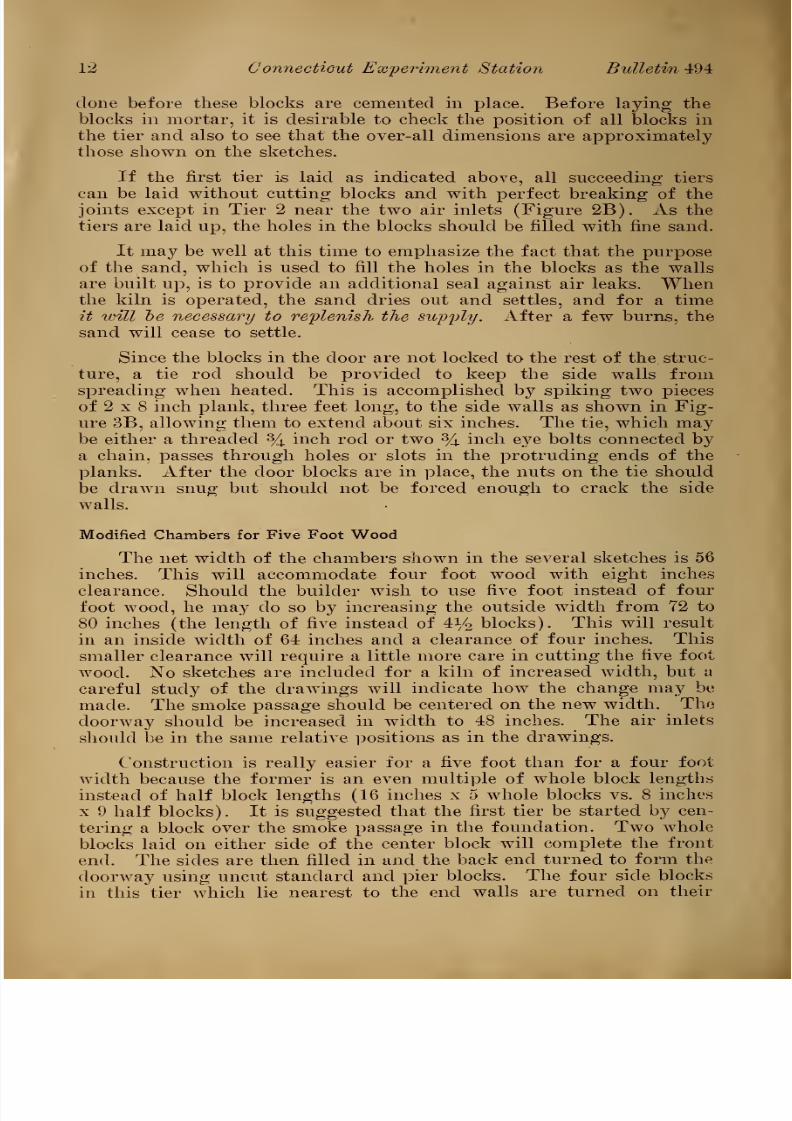
done before these blocks are cemented in place. Before laying the
blocks in mortar, it is desirable to check the position of all blocks in
the tier and also to see that the over-all dimensions are approximately
those shown on the sketches.
If the first tier is laid as indicated above, all succeeding tiers
can be laid without cutting blocks and with perfect breaking of the
joints except in Tier 2 near the two air inlets (Figure 2B). As the
tiers are laid up, the holes in the blocks should be filled with fine sand.
It may be well at this time to emphasize the fact that the purpose
of the sand, which is used to fill the holes in the blocks as the walls
are built up, is to provide an additional seal against air leaks. Whenthe kiln is operated, the sand dries out and settles, and for a time
it will be necessary to replenish the supply. After a few burns, the
sand will cease to settle.
Since the blocks in the door are not locked to the rest of the struc-
ture, a tie rod should be provided to keep the side walls from
spreading when heated. This is accomplished by spiking two pieces
of 2 x 8 inch plank, three feet long, to the side walls as shown in Fig-
ure 3B, allowing them to extend about six inches. The tie, which maybe either a threaded % inch rod or two % inch eye bolts connected by
a chain, passes through holes or slots in the protruding ends of the
planks. After the door blocks are in place, the nuts on the tie should
be drawn snug but should not be forced enough to crack the side
walls.
Modified Chambers for Five Foot Wood
The net width of the chambers shown in the several sketches is 56
inches. This will accommodate four foot wood with eight inches
clearance. Should the builder wish to use five foot instead of four
foot wood, he may do so by increasing the outside width from 72 to
80 inches (the length of five instead of 4i/2 blocks). This will resultin an inside width of 64 inches and a clearance of four inches. This
smaller clearance will require a little more care in cutting the five foot
wood. No sketches are included for a kiln of increased width, but a
careful study of the drawings will indicate how the change may be
made. The smoke passage should be centered on the new width. The
doorway should be increased in width to 48 inches. The air inlets
should be in the same relative, positions as in the drawings.
Construction is really easier for a five foot than for a four foot
width because the former is an even multiple of whole block lengthsinstead of half block lengths (16 inches x 5 whole blocks vs. 8 inches
x 9 half blocks). It is suggested that the first tier be started by cen-
tering a block over the smoke passage in the foundation. Two whole
blocks laid on either side of the center block will complete the front
end. The sides are then filled in and the back end turned to form the
doorway using uncut standard and pier blocks. The four side blocks
in this tier which lie nearest to the end walls are turned on their

8/12/2019 Charcoal Kiln Made 00 Ol So
http://slidepdf.com/reader/full/charcoal-kiln-made-00-ol-so 13/32
A Charcoal Kiln Made of Cinder-Concrete Blocks 13
sides to form air inlets as previously described. The second tier can
then be laid upon the hrst, using uncut standard, pier and half blocks.
and all joints will break perfectly. The third tier is an exact rep-
lica of the first; the fourth, of the second and so on. The position
and type of the blocks in the same tier, but on opposite sides of the
chamber, are identical.
Building the Top
The top or roof of the kiln is formed of 4 x 8 x 16 inch partition
blocks and 64-inch lengths of 114 inch iron or steel pipe. The two
outside holes in the blocks are reamed out and seven blocks are
threaded on two lengths of pipe to form a panel 16 inches wide and
56 inches long. To assemble a panel, place seven
1 blocks,side by
side.
on a plank laid across the side walls, push the two pipes through the
reamed holes and then slide the whole panel into place with the pipe
ends resting on the side walls. This will be found much easier than
assembling on the ground and lifting into place. The center block in
the front panel (labeled Inspection Block in Figure 2B) rests on
top of the pipes and is easily removed. This block serves several pur-
poses. It may be removed for inspection while the kiln is in oper-
ation. It should be removed several hours before the kiln is opened
after cooling to make sure there is no fire in the charcoal. It should
be left off while discharging charcoal to provide ventilation.
Reaming out the holes is a rather tedious job. However, the
work can be greatly facilitated by use of a tool made by filing saw
teeth in one end of a piece of l1/^ inch iron pipe, 18 inches long. Toream the holes, place the block on the ground (not on a hard surface),
start the tool at the small end of the hole in the block and continue
reaming by striking the end of the tool lightly with a hammer. The
tool should be rotated slightly after each blow.
After all the panels are in place, the blocks should be spaced
evenly on the pipes and their top surfaces plastered with a one inchcoat of lime mortar. The entire top should then be covered with a
layer of fine sand or soil two inches thick to complete the seal. This
layer should be maintained at all times.
A top so constructed will bear the weight of two or three men.
However, it is advisable to lay two planks lengthwise of the kiln on
top of the sand to serve as a catwalk. This will distribute any mov-
ing loads more evenly and prevent failures which might occur from
local overloading.
To complete the chamber for operation, it will be necessary to
drill holes for firing ports in each side wall just above ground line
and to provide a metering device for the air inlets. The ports drilled
are just large enough to accommodate a piece of l1/^ inch pipe, nine
inches long, which is cemented in place. The position of the ports
1 If the top is for a chamber to house five foot wood, eight blocks will be neededfor each panel.

8/12/2019 Charcoal Kiln Made 00 Ol So
http://slidepdf.com/reader/full/charcoal-kiln-made-00-ol-so 14/32
14 Connecticut Experiment Station Bulletin 494
relative to the ends of the kilns is shown in Figures 2A and 2B. Thepurpose of the metering device is to provide an opening of knowncross-sectional area for each air inlet. This may be done in a variety
of ways. Perhaps the simplest is to rabbet the edges of two strips
of wood, each | x 2 x 10 inches, to accommodate a thin metal slide.
Nail these strips on either side of the inlet opening with their edges
vertical and parallel and cut a thin metal slide to fit the rabbet. Makesure that no air enters the inlet except through the opening formed
by the slide.
Building the Chimney Stove
The chimney stove is a rectangular box which abuts the front end
of the chamber and whose interior dimensions are length, 48 inches;depth, 16 inches, and width, 12 inches. It will be noted from Figure
2A that one half its depth is below ground line. It is divided into
two unequal parts by a baffle. The front part serves as a fuel cham-
ber where fire is maintained during part of the burn to induce chim-
ney draft. The back part forms a connecting passage between the
smoke outlet under the chamber wall and the chimney. See Figures
1A, 1C and 4B.
The upper block in the front wall is removable for fueling the
stove, and air is admitted through a hole dug under the lower block in
the same wall to maintain fire.
The top of the chimney stove is made up of four 4 x 8 x 16 inch
cinder blocks and a piece of sheet steel, % x 20 x 32 inches, in which a
hole is cut to admit eight-inch chimney flue pipe. The top of the
chimney should extend 10 inches above the coaling chamber walls
regardless of the height of these walls. When the burn is in pro-
gress, the chimney pipe is set in place over the hole in the steel plate.
To prevent the chimney from sliding through the plate, cut three pairs
of slits, about one inch long, in the lower end of the pipe parallel to
its axis. The slits making up a pair should be about one inch apart
and the pairs should be spaced about equally around the perimeter of
the pipe. After cutting, bend the one inch pieces outward at right
angles to form ears which will rest on the plate and prevent the
chimney from sliding through. A piece of Vs x V2 mcn strap iron,
nailed to the front wall of the chamber, will hold the chimney in a
vertical position (Figure 3A). Since the chimney is removed during
the cooling period, it should not be permanently fastened to the brac-
ing iron. When the chimney is not in place, the hole in the steel plate
may be covered by any small metal plate that will span the gap. Toprevent leaks, the entire stove, except the front end, is covered with
sand or soil (see inside front cover).
KILN OPERATION
Process of Coaling
In kilns operated by the admission of air, the process of coaling
is a progressive one. It consists in first bringing a relatively small

8/12/2019 Charcoal Kiln Made 00 Ol So
http://slidepdf.com/reader/full/charcoal-kiln-made-00-ol-so 15/32
A Charcoal Kiln Made of Cinder-Concrete Blocks J
portion of the charge up to charring temperature by direct firing.
This results in the initiation of a coaling zone which then moves
though the wood mass in response to air admitted to the kiln. This
start of a coaling zone is always at some point near the top of the kiln.
The shape of the zone will vary with the shape of the kiln and it-
direction of movement Avill always be toward the source of air sup-
ply. In kilns of rectangular shape, the coaling zone (or zones) has
the shape of a thin bent plane. If fired near the middle, as in the
kilns herein described, two such coaling zones are developed. Move-
ment of these is outward toward the ends of the kiln and also down-
ward toward the air inlets. The two pairs of solid lines marked 1
in Figure 4A indicate the relative positions of the two coaling zones
in a two-cord kiln after several hours of operation. Coaling was in-
itiated at point X directly above the firing ports. Later the zones
move farther away from each other. Successive positions of the two
zones during the burn are marked 2, 3, etc.
The coaling zones are only a few inches thick and, for that rea-
son, the amount of wood actually being charred at any one time is a
relatively small percentage of the whole charge. Ahead of the zone,
as it moves, is uncharred wood; behind it is charcoal, which occupies
a little more than half the space originally occupied by the wood.
The objective sought in coaling is to have the two zones approach
the forward and rear air inlets at approximately the same time, leav-
ing an even bed of charcoal the entire length of the kiln. This is
accomplished by regulating the amount of air admitted at these in-
lets. To compensate for the chimney being located at one end, the
firing ports are off center, fore and aft. Since the volume of woodaft of the firing ports is less than that forward, the rear (B) air
inlets are regulated to admit less air than the front (A) air inlets.
The rate of coaling for the charge as a whole is governed by the
amount of chimney draft.
Loading
Loading is begun by laying two wooden stringers, four inches in
diameter, on the floor of the kiln, parallel to the side walls and about
18 inches from them. These stringers are discontinuous in front of
the firing ports (Figure 4B). Next stand two struts, three to four
inches in diameter, against the front wall to permit a free passage for
the smoke to the smoke outlet under this wall. Stand a 16 x 20 inch
piece of heavy (12 guage) hardware cloth with y2 inch niesh slant-
wise against the front wall to prevent falling charcoal from blocking
the smoke outlet.
For stacking in the kiln, the wood should be rough-graded into
three sizes and used as follows
(a) Small, including sticks two to three inches in diameter,
which should be placed on the stringers to a depth of 12 inches and in
the zone directly above the kindling (see Figure IB).

8/12/2019 Charcoal Kiln Made 00 Ol So
http://slidepdf.com/reader/full/charcoal-kiln-made-00-ol-so 16/32
10 Connecticut Experiment Station Bulletin 494
(b) Medium, including sticks four to five inches in diameter,
which may be used anywhere in the kiln.
(c) Large, including sticks, six inches and over in diameter,
which should be placed above the middle of the kiln and near the end
walls. All sticks over seven inches in diameter should be split.
All wood is piled at right angles to the stringers and should be
packed as closely as possible (Figure 4B). Piling should be started
against the struts and proceed toward the firing ports. When these
are reached, lay kindling and oil soaked rags between them. Abovethe kindling, pile brands, dry wood and small wood to half the height
of the kiln. Continue piling toward the rear end, using the several
sizes of wood as recommended above. While loading, be sure that
the air inlets and firing ports do not become clogged with bark or
other material.
When charging is completed, lay the door blocks in position with-
out mortar as shown in Figure 2B. Point up the joints on the outer
face of these blocks and the joint between the top tier of blocks and
the roof with lime mortar. Lay bricks over the holes in the top tier
of blocks and cover with sand. Snug up the tie rod. The kiln is nowready to fire.
Firing
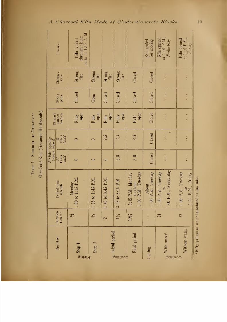
A complete operations schedule (Tables I and II) will be pre-
sented later for both sizes of kiln when used with seasoned hard-
woods. Firing procedure, which extends over a period of 45 minutes
is the same for both. Its purpose is to bring a portion of the wood
in the chamber up to coaling temperature in preparation for the for-
mation and later movement of the coaling zones. Firing is accom-
plished in two steps:
(1) With all air inlets and firing ports closed and the chimney
clamper fully open, the chimney stove is charged with wood, fired and
allowed to burn strongly to induce a good draft in the chimney.
(2) After 15 minutes the firing ports are opened and the charge
in the chamber is ignited by pushing a lighted taper through the two
ports which are left open for % hour. During this period the air
inlets are closed and the chimney damper is in a fully open position.
Fuel is added to the chimney stove as needed to maintain a good chim-
neydraft.
This completes the firing period at the end of which both firing
ports are closed and banked with sand or soil. The kiln is now ready
to start coaling.
Coaling
The object from now on will be to develop the coaling zones and
to conduct them through the wood at a rate which will result in com-

8/12/2019 Charcoal Kiln Made 00 Ol So
http://slidepdf.com/reader/full/charcoal-kiln-made-00-ol-so 17/32
A Charcoal Kiln Made of Cinder-Concrete Blocks 17
pletion of the burn at both ends of the kiln at approximately the same
time. The time required to coal is different for the two sizes of kiln
but the steps in the procedure are the same for both. They an- a
follows
(1) Initial coaling period. The chimney damper remains wide
open and a strong fire is maintained in the chimney stove. At the
beginning of this period, both B Air Inlets are opened ; later the AAir Inlets are opened. (See Tables I and II). This period lasts 3%hours for the one-cord and five hours for the two-cord kiln. When it
is over, the chimney damper is set in a half open position. Coal-
ing action is noAV strong enough to maintain its own draft without fire
in the chimney stove and the latter is closed and banked.
(2) Final coaling period. With the air inlet openings anddamper set as described at the end of the initial coaling period, the
kiln is now ready to coal through without further attention. This
will require about 20 hours for the one-cord kiln and 37 hours for th^
two-cord kiln. As the end of this period approaches, the operator
should be on hand to close the kiln.
Closing and Cooling
If the wood has been properly stacked in the kiln and the air in-
let openings have been of the right size, the coaling zones should reach
all the air inlets within an hour. As the zone approaches an inlet,
glowing charcoal will be visible and the inlet should be closed and
banked with soil. The other inlets should be closed and banked as
soon as a glow is visible but, if any fails to glow within an hour, all
should be closed and banked to prevent local burning of charcoal.
After the inlets have all been closed, the chimney should be re-
moved and the hole in the steel plate covered and banked with soil.
The kiln should be inspected carefully for leaks in the walls and top.
Leaks in the latter may be stopped with sand. Leaks in the walls
may be plugged by brushing with creamy lime mortar.
The kiln must now cool down. This will require three days for
the one-cord and five days for the two-cord kiln. This cooling period
may be reduced 60 per cent by introducing water into the kiln in the
form of a fine mist as soon as it is closed. If water is used, one block
near the top of the door panel should be laid wTith the holes horizontal.
One of these holes should be plugged firmly. Into the other, cement
a short piece of pipe of sufficient diameter to accommodate the spray
nozzle and to permit steam to escape (see Figure 3B). The pipe
should be plugged when not in use. The water should be introduced
under sufficient pressure to insure a very fine mist and pumping
should cease when steam formation ceases.
It will take about 50 gallons of water for the one-cord and 80
gallons for the two-cord kiln. If mist is used, the one-cord may be
opened and discharged after 24 hours of cooling. The two-cord kiln
will require 48 hours to cool.
8/12/2019 Charcoal Kiln Made 00 Ol So
http://slidepdf.com/reader/full/charcoal-kiln-made-00-ol-so 18/32
18 Connecticut Experiment Station Bulletin 494
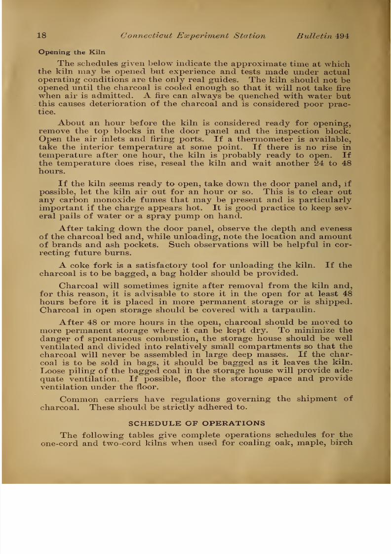
Opening the Kiln
The schedules given below indicate the approximate time at whichthe kiln may be opened but experience and tests made under actual
operating conditions are the only real guides. The kiln should not be
opened until the charcoal is cooled enough so that it will not take fire
when air is admitted. A fire can always be quenched with water but
this causes deterioration of the charcoal and is considered poor prac-
tice.
About an hour before the kiln is considered ready for opening,
remove the top blocks in the door panel and the inspection block.
Open the air inlets and firing ports. If a thermometer is available,
take the interior temperature at some point. If there is no rise in
temperature after one hour, the kiln is probably ready to open. Ifthe temperature does rise, reseal the kiln and wait another 24 to 48
hours.
If the kiln seems ready to open, take down the door panel and, if
possible, let the kiln air out for an hour or so. This is to clear out
any carbon monoxide fumes that may be present and is particularly
important if the charge appears hot. It is good practice to keep sev-
eral pails of water or a spray pump on hand.
After taking down the door panel, observe the depth and eveness
of the charcoal bed and, while unloading, note the location and amount
of brands and ash pockets. Such observations will be helpful in cor-
recting future burns.
A coke fork is a satisfactory tool for unloading the kiln. If the
charcoal is to be bagged, a bag holder should be provided.
Charcoal will sometimes ignite after removal from the kiln and,
for this reason, it is advisable to store it in the open for at least 48
hours before it is placed in more permanent storage or is shipped.
Charcoal in open storage should be covered with a tarpaulin.
After 48 or more hours in the open, charcoal should be moved to
more permanent storage where it can be kept dry. To minimize the
danger of spontaneous combustion, the storage house should be well
ventilated and divided into relatively small compartments so that the
charcoal will never be assembled in large deep masses. If the char-
coal is to be sold in bags, it should be bagged as it leaves the kiln.
Loose piling of the bagged coal in the storage house will provide ade-
quate ventilation. If possible, floor the storage space and provide
ventilation under the floor.
Common carriers have regulations governing the shipment of
charcoal. These should be strictly adhered to.
SCHEDULE OF OPERATIONS
The following tables give complete operations schedules for the
one-cord and two-cord kilns when used for coaling oak, maple, birch
8/12/2019 Charcoal Kiln Made 00 Ol So
http://slidepdf.com/reader/full/charcoal-kiln-made-00-ol-so 19/32
A charcoal Kiln Made of Cinder-Concrete Blocks 19
o E
W
u
IKiln
ignited
through
firing
ports
at
1:15
P.
M.
-a bo
CU Oen o^ o
Kiln
opened
at
1:00
P.M.,
Wednesday
Kiln
opened
at
1:00
P.M.,
Friday
5 <O s-.
CO
be
S wO u
CO
be
C (DO s-h
1- ;~
CO
O ii
CO
a -aCU <D'Si 'Si
c o
U U
.Jj O
en
o
UPh
o
en
o
Uo
U
T3<uSi
O
U
CDen
C
U
g-3 §,
>, 53
r=: a3 o
~ p3 O 3 O
M-i W
c3 OX
a<den
O
U
.5 3
fag
o ol-O
CM CM
l-O
CM
to
en
o
u
o o OOCO
OCO
TJ<uen
o
u
a. 3
5§-o
oo
o
Ph'
£
CO
O
l-O
Ph
IT)
o
CO
5:15
P.M.,
Monday
to
about
1:00
P.M.,
Tuesday
;>>
rt
*aen
<U
o -
%%.Ph
oo1:00
P.M.,
Tuesday
to
1:00
P.M.,
Wednesday
1:00
P.M.,
Tuesday
to
1:00
P.M.,
Friday
Duration(hours)
^ «CM 5 0\
CMCM
c
ia
u
oCO
Suiju
CM
c
CO
I
C
f-
ae
)
oUIp30
X)o
3
C
EbJD
en
C
U
u
iSuijo
u
Ho
1
3D

8/12/2019 Charcoal Kiln Made 00 Ol So
http://slidepdf.com/reader/full/charcoal-kiln-made-00-ol-so 20/32
20 Connecticut Experiment Station Bulletin 494
S £
o
14
B <u
g *o
,_
oft
3 -w
S S
o oPnu ae b/iTt
2f-S t-h
u£<-£
_/
T3 r
2 rt
CJ
PL)
s a>^5
Pn Ph Ph
l-O-1-
r-H + oQ o o
m IT)
-t
rt '-< •+
Pm pc
,X
r
S>1 J >>
— <*in o <
g <U
00 o<U 1)
> S>O^<
o c
3j:
p^
CO
Pm
fe
*a -
CD aS
a, . -ao<§
X b£ be be bJL Td -oJ <u S • C tu S (L)
<L> 0J
O U O S- O I-. O ;_
U co CO CO CO u U
_, n3 *d T3CU o CD CD <u CD
crt C/3 c/3
c O O O o
E a U U U U U
X . r- ^ >-. s >> c >, a it cCDC/3
o1 s
:
lr^ aJ o
—i cy
£ °
:=3 <u
Cy O
—] CD
£ °
^5 <l>
;
o o o o oC/J
CO CO CO o
u
<
.SllfJUf SUIJBOJ .Sui[oo3

8/12/2019 Charcoal Kiln Made 00 Ol So
http://slidepdf.com/reader/full/charcoal-kiln-made-00-ol-so 21/32
A Charcoal Kiln Made of Cinder-Concrete Blocks 21
and other dense woods cut in the winter and seasoned in the pile dur-
ing the following summer. The moisture content ranged from 30 to 40
per cent (dry basis). The sticks ranged in diameter from three to
seven inches and the material could be classified as grade 1 hardwoodfuel.
These schedules should be used by the operator as a guide. They
have been employed successfully with the kind of wood described
above and, with minor modifications, on wood of other species, sizes
and moisture content. It should be remembered, however, that wood is
an extremely variable substance. No two lots are ever quite alike even
though they may appear to be. The human element must also be
taken into account, since people do not react alike to instructions or
to conditions. So, in the last analysis, the operator must modify the
instructions to suit his own conditions. The schedules have been so
arranged that practically all the labor required can be done within the
limits of the ordinary work day.
The time required to charge with wood and unload the charcoal
is approximately five man-hours for the one-cord kiln and eight man-
hours for the two-cord kiln. If several kilns are operated as a bat-
tery, the intermittent labor required during the firing and initial
coaling periods can be performed on one kiln while another is being
charged or discharged.
DISCUSSION
Under this heading are included a number of more or less un-
related statements, based on experience, which may help the operator
in gauging his operation.
Rate of Coaling
A good burn is characterized by an even bed of firm, black char-
coal which does not break up readilj7,which has a small percentage of
fines, and which contains fewT
or no brands or ashes.
Charcoal produced from the denser woods such as oak, maple,
birch and ash will, under the same coaling conditions, be heavier
than charcoal from light wToods such as basswood, aspen and most
conifers. Weight per unit of volume is, consequently, not an indi-
cation of a poor burn. If, however, the charcoal is not only light in
weight, but also breaks up readily into small pieces, it is an almost
certain indication that the burn was made too quickly. To remedy
this, close the chimney damper slightly on the next burn.
A burn which has been conducted too slowly will usually have apocket of ashes near the firing ports and an excessive amount of
brands near the ends of the kiln. Apparently what happens is that
the air supply coming in at the air inlets is insufficient to keep the
coaling zones moving but is sufficient to cause local burning of char-
coal already formed. The remedy is to open the chimney damperslightly on the next burn.
8/12/2019 Charcoal Kiln Made 00 Ol So
http://slidepdf.com/reader/full/charcoal-kiln-made-00-ol-so 22/32
22 Connecticut Experiment Station Bulletin 494
The range between the coaling rate of a burn that has been run
too fast and one that has been run too slowly is comparatively small.
A burn conducted at a fast rate will be successful in that most of
the wood will be coaled. The charcoal, however, will be light. Itmay be entirely satisfactory for some uses, but it is unsatisfactory to
the producer who sells by weight instead of by volume. A burn which
is conducted too slowly will, as indicated above, not only coal badly or
not at all, but will also burn up the charcoal as fast as it is made.
Such a condition should be avoided at all costs.
Chimney Draft
The amount of chimney draft and, consequently, the speed of the
burn, is governed by the damper setting. After the chimney stovehas been closed, this setting varies between y2 and % open and, in
the absence of instruments, is gauged by the position of the damper
handle relative to a quadrant scribed on the chimney. One side of
the quadrant should be parallel to the long axis of the chimney.
Experimental evidence indicates that the draft should be equiva-
lent to about 0.02 inch of water pressure. If a draft gauge is avail-
able, much more consistent results will be obtained if the damper is
set to conform with a desired draft gauge reading than if it is set by
quadrant.
Character of the Smoke
Color and volume of the smoke issuing from the chimney about
one hour after the chimney stove has been closed and banked are good
indicators of coaling progress, once one has learned to evaluate them.
When the kiln is coaling satisfactorily, there should be a good volume
of grayish-white smoke. If the volume of smoke is small, coaling is
probably progressing too slowly and the damper opening should be
increased. An appreciable amount of yellow color in the smoke indi-
cates that coaling is progressing too rapidly and the damper opening
should be decreased. The volume and color of the smoke should re-
main fairly constant until near the end of the final coaling period, at
which time the smoke tends to thin out and turn bluish. This indi-
cates that it is nearly time to close the kiln.
Tar Formation
Toward the end of the burn, tar collects in increasing quantities
on the inside surface of the chimney pipe near its base. Here, it is
coked into a fairly hard, highly porous mass which may entirely
block the chimney. Blocking usually manifests itself by a lessening
of the volume of smoke, without a change to a bluish color, before
glowing appears at the air inlets. The tar mass may be removed by
running a long slender pole down the chimney pipe. It is a good
practice to perform this operation two or three times during the last
two hours of the final coaling period to make sure the chimney is
clear.

8/12/2019 Charcoal Kiln Made 00 Ol So
http://slidepdf.com/reader/full/charcoal-kiln-made-00-ol-so 23/32
A Charcoal Kiln Made of Cinder-Concrete Blocks 23
Brands
An ideal burn would be one entirely free of brands. Such a con-
dition is seldom attained. As the coaling zones approach the air in-
lets, the charcoal formed begins to glow in response to the incomingair. Glowing usually occurs before the wood is all coaled through.
If it continues until all the wood is coaled, an appreciable loss of
charcoal takes place through combustion. It is better, therefore, to
close the kiln within an hour after glowing is visible. By this prac-
tice, a few brands will be found near the end walls, but these can be
coaled on the next burn. The total volume of brands left in a good
burn in either the one-cord or the two-cord kiln should be one-tenth
of a cord or less.
Brands may also result from mixing green or dozy wood withseasoned wood, from attempting to coal too large sticks or from con-
ducting a burn too slowly. A correction in operational technique will
eliminate brands arising from these causes.
Size and Shape of Wood
All sizes of wood up to seven inches in diameter can be coaled suc-
cessfully. Larger pieces should be split. The sticks should be rea-
sonably straight to facilitate close piling in the kiln. A cord of woodmade up of sticks of small diameter will contain much less wood sub-
stance and, consequently, produce much less charcoal than a cord
composed of sticks of large diameter. The wood should be sound.
With wood of a moisture content approximating that indicated in
the tables above, sticks of smaller average diameter (two to four
inches) should be coaled with slightly smaller air inlet openings and
slightly less chimney draft than is indicated in the tables. Larger
diameter sticks (five to seven inches) require slightly larger air inlet
openings and slightly more chimney draft than is indicated in the
tables.
Coniferous and hardwood slabs can be coaled with good yields,
the operational procedure being much the same as for cordwood of
about the same moisture content.
The two following statements are estimates by the authors and are
not based on experience.
(1) It should be possible to use the kilns to coal odd shaped
pieces of refuse wood such as trimmings, blocks, etc., which accumu-
late around wood working establishments, proAricled the moisture con-
tent is not too low and the pieces do not vary too much in size. It
would be necessary to floor the stringers with scrap boards (spaced 1
inch apart) and to face the struts with the same material. It might
also be necessary to bridge the air inlets on the inside to prevent stop-
page with small pieces of wood.
It will probably not be feasible to hand pack material of this
kind. It would seem that the most satisfactory method of loading

8/12/2019 Charcoal Kiln Made 00 Ol So
http://slidepdf.com/reader/full/charcoal-kiln-made-00-ol-so 24/32
24 Connecticut Experiment Station Bulletin 494
would be to remove the center top panel and dump the pieces through
the opening, raking them as they fall to settle them into place. Un-der these conditions the pieces would not be very closely packed and
the yields would, consequently, be rather low. An operations schedulewould have to be worked out.
(2) It seems almost certain that sawdust, shavings, hogged woodand similar small waste cannot be coaled in these kilns. Circulation
of air is necessary to the movement of the coaling zones. Fine ma-terial packs so tightly that such circulation would be almost com-
pletely shut off.
Moisture Content (dry basis)
Wood of any moisture content can be carbonized but, from a prac-
tical standpoint, the moisture content should probably be between 20
and 80 per cent. The lower figure will be about the minimum for
thoroughly air-dried wood in the northeastern United States. The
higher figure is about the average for unseasoned northern hardwoods.
Although no wood of low moisture content (below 20 per cent)
was coaled in the kilns described, the literature on carbonization in-
dicates that such wood does not coal readily or produce good yields.
Kiln dried scrap lumber would fall in this category.
The best results with the kilns were obtained when coaling wood
with less than 40 per cent moisture. Good results were also obtained
with unseasoned hardwoods (moisture content about 80 per cent), the
yields being about 80 per cent of those from the same kinds of wood
which had been seasoned during one summer. Unseasoned conifers
generally have a much higher moisture content than hardwoods (in
some cases 150 to 200 per cent or 400 gallons of water per cord) and,
while they can be coaled, the yields are very low. These can be im-
proved very materially by one to two months of summer seasoning in
the open. In one case where this was done with Scotch pine, theyield was increased from 19 to 29 bushels per cord or about 55 per cent.
When coaling unseasoned hardwoods and semi-seasoned conifers,
it was found necessary to increase the size of the air inlet openings by
approximately 50 per cent over the values given in the tables and to
have the chimney damper three-quarters instead of one-half open.
It is not considered good practice to mix seasoned and unseasoned
wood in the same charge nor to coal wood which has become dozy .
Table 3 shows the yields obtained with a
numberof different
species and from woods of different moisture contents.
Inspection and Care of the Coaling Chamber
The coaling chamber requires little care beyond keeping it sealed
tightly during the coaling and cooling periods, except for air pur-
posely admitted through the air inlets and firing ports. Without

8/12/2019 Charcoal Kiln Made 00 Ol So
http://slidepdf.com/reader/full/charcoal-kiln-made-00-ol-so 25/32
A Charcoal Kiln Made of Cinder-Concrete Blocks 25
Table 3. Yields
Estimated moisture , .., , ,,
contentYield per cord* Number ol
Wood coaled (oven dry basis)
In In burns(per cent) bushels2 pounds
Seasoned, mixed hardwoods 30 - 40 46 920 6
Unseasoned hardwoods (Oak) 80 38 760 2
Semi-seasoned Scotch pine . . 65-75 29 580 4
Unseasoned Scotch pine More than 150 19 380 3'
Unseasoned white pine
slahwood 65-75 33 660 1
Unseasoned white pine
topwood 65-75 .26 520 4
1 Ni-t yield of lump charcoal, excluding' uncoaled wood (brands) and fine charcoal.
- In Connecticut, a legal bushel of charcoal weighs 20 pounds.
adding greatly to the cost of construction, it would be almost impos-
sible to make the chamber absolutely leak proof. Nor is this neces-
sary. Small leaks will develop from time to time but these can be
very easily closed and need cause no trouble if the kiln is inspected
systematically. This is particularly important during the first half
dozen burns. Sand settles in the core holes in the blocks and small
leaks developdue to poor mortar
joints or to porosity in the blocks
themselves. The core holes should be refilled until the sand ceases to
settle. The top should also be kept covered with a layer of sand.
Small leaks in vertical surfaces and around the door blocks are easily
stopped by brushing over with creamy lime mortar, a pail of which
should be on hand at all times. Leaks will become less frequent as
time goes on, due to plugging from the inside with tar. This, how-
ever, does not do away with the need for frequent inspections.
The best time to make these is within an hour after the kiln is closed
and banked for cooling. Action continues for a while after the air is
shut off and apparently a slight pressure is developed which forces thesmoke out through small leaks which are not discernible during coal-
ing.
Leaks are not particularly important during the coaling period
unless they are too large or too numerous. In such cases they act as
added air inlets and disrupt the schedule. They are very important
during the cooling period, when no air should be allowed to leak into
the kiln, and should be guarded against by all possible means.
Life of the Kilns
The experimental kilns have been used for more than 50 burns
without deterioration except for a little erosion on the inner surfaces
of several blocks adjacent to the firing ports. These blocks are still
serviceable but would have to be replaced if the kiln were moved. Onthe basis of this experience, it is estimated that the kilns should re-
main serviceable for 100 or more burns if they are not moved. If they

8/12/2019 Charcoal Kiln Made 00 Ol So
http://slidepdf.com/reader/full/charcoal-kiln-made-00-ol-so 26/32
26 Connecticut Experiment Station Bulletin 494
are dismantled and rebuilt, there would undoubtedly be some break-
age. The excellent condition of the door blocks, which have been
taken down and relaid more than 50 times, indicates that deterior-
ation should be relatively small.
Winter Operation
Experience with the kilns indicates that they are most easily
operated when the temperature is above about 20° F. If they must be
operated at lower temperatures, the kilns should be housed and pro-
vision made to keep the wood reasonably dry. The chimney should be
insulated and the ground around the kiln should be ditched to provide
good drainage.
Bill of Materials
Kind of material Nominaldimension
Number of pieces
One-cord kiln Two-cord kiln
Cinder-concrete blocks1
(Hollow type)
Standard 8 x 8 x 16 1451
2251
Pier 8 x 8 x 16 341
351
Half-block 8 x 8 x 8 91
ll1
Partition 4 x 8 x 16 481
621
1J4 iron or steel pipe2 64 long 12 16
1J4 iron or steel pipe2 9 long 2 2
2 iron or steel pipe2 9 long 1 1
Strap iron
(chimney brace) % x y x 40 1 1
Steel plate % x 20 x 32 1 1
Wire cloth,
Y\ mesh12 ga. wire 16 x 20 1 1
Tie rod—34 rod or chain
with eye bolts for 76 span 1 1
8 flue pipe (metal) 5 2/3 linear feet 7 linear feet
Flue pipe damper for 8 flue pipe 1 1
Wood plank 2 x 8 x 36 2 2
Sand 2 x/ cubic yards 3 cubic yards
Lime 160 pounds 240 pounds
Cement (optional)
1 The number of blocks specified is the actual number needed to construct that por-tion of the chamber which is above ground line, to build all of the chimney stove andto line the trench within the chamber. Any blocks used in the foundations will be in
addition to those listed. To allow for breakage, it is recommended that the numberspecified be increased as follows : standard and pier blocks combined, five ; halfblocks, two, and partition blocks, ten.
2 New or used.

8/12/2019 Charcoal Kiln Made 00 Ol So
http://slidepdf.com/reader/full/charcoal-kiln-made-00-ol-so 27/32
8/12/2019 Charcoal Kiln Made 00 Ol So
http://slidepdf.com/reader/full/charcoal-kiln-made-00-ol-so 28/32
28 Connecticut Experiment Station Bulletin 494
AIR INLET A-
FIRING PORT
AIR INLET B
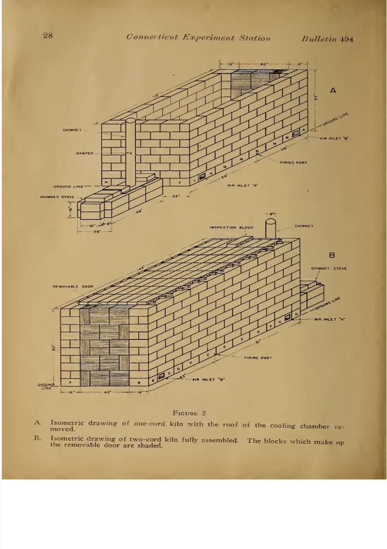
Figure 2
A. Isometric drawing of one-cord kiln with the roof of the coaling chamber
B. Isometric drawing of two-cord kiln fully assembled. The blocks which makethe removable door are shaded.
up

8/12/2019 Charcoal Kiln Made 00 Ol So
http://slidepdf.com/reader/full/charcoal-kiln-made-00-ol-so 29/32
A Charcoal Kiln Made of Cinder-Concrete Blocks 29
CHIMNEY BRACE
SReUNO LINE
FOUNDATION BLOCKS
FOUNDATION TIMBERS
SMOKE OUTLET
\s7?
^/
TIE ROD
i
1
—— -- ====^
GROUND LINE 1
^^ m^=
Figure 3
Isometric drawing of the front end of two-cord kiln with chimney stove re-moved. The foundations are for a temporary installation and consist of timbers
and an extra tier of blocks. Xote the smoke outlet through the foundation and
the chimnev brace.
B. Isometric drawing of the rear end of two-cord kiln showing removable door
and tie rod. Foundations of field stone and concrete are for a permanent in-
stallation. The hole near the top of the door is for the admission of water
during cooling.

8/12/2019 Charcoal Kiln Made 00 Ol So
http://slidepdf.com/reader/full/charcoal-kiln-made-00-ol-so 30/32
30 Connecticut Experiment Station Bulletin 494
B
TYPES OF BLOCKS
A.
B.
o»i
Figure 4
Vertical section through two-cord kiln illustrating movement of the coaling zones
through the wood mass during carbonization.
Vertical section through two-cord kiln showing position of stringers and struts
and placement of the kindling and the several sizes of wood. Brands are shown
in solid black.
Isometric drawings of the four types of cinder-concrete blocks used in con-
struction of the kilns. Dimensions shown are nominal.

8/12/2019 Charcoal Kiln Made 00 Ol So
http://slidepdf.com/reader/full/charcoal-kiln-made-00-ol-so 31/32

8/12/2019 Charcoal Kiln Made 00 Ol So
http://slidepdf.com/reader/full/charcoal-kiln-made-00-ol-so 32/32