
Char-forming behavior of nanofibrillated cellulose treated ...
CHARACTERIZING NANOFIBRILLATED
CELLULOSE FROM OIL PALM EMPTY FRUIT
BUNCH AND ITS INFLUENCE AS
REINFORCEMENT AGENT IN EPOXY BASED
NANOBIOCOMPOSITE
IREANA YUSRA BINTI ABDUL FATAH
UNIVERSITI SAINS MALAYSIA
2015

CHARACTERIZING NANOFIBRILLATED CELLULOSE FROM
OIL PALM EMPTY FRUIT BUNCH AND ITS INFLUENCE AS
REINFORCEMENT AGENT IN EPOXY BASED NANOBIOCOMPOSITE
By
IREANA YUSRA BINTI ABDUL FATAH
Thesis submitted in fulfillment of the requirements
for the degree of
Doctor of Philosophy
SEPTEMBER 2015

ii
ACKNOWLEDGMENT
First and foremost, I would like to express my greatest gratitude to Allah the
Al-Mighty for enabling this thesis writing to be brought to its successful conclusion.
Without His mercy and blessing, this endeavor would not have been successful.
Next, I would like to thank Prof. Datuk Dr. Abdul Khalil Shawkataly, my supervisor,
for his strong support, encouragement, and guidance in completing this thesis.
Special thanks also go to Dr. Astimar Abdul Aziz as my co-supervisor in MPOB for her
counsel and help throughout this research.
My incredible thanks to Malaysia Palm Oil Board (MPOB) and Universiti
Sains Malaysia for providing the research fellowship and research grant funding
(USM-RU-PRGS, Grant No: 1001/PTEKIND/846107).
My sincere gratitude goes to my beloved parents, Abdul Fatah Che Hamat
and Nor Eynizan Hassan, parents in law and all my family members, for their prayers,
love, constant support and understanding. Likewise, to my beloved husband, Nik
Ahmad Firdaus and my daughter, Nik Qhayra Safiyya, I would like to say “a million
thanks” for lending support and encouragement, as well as showing patience,
understanding and tolerance during my trying moments.
I wish to thank all of my friends and colleagues, both seniors and juniors
from School of Industrial Technology and MPOB, they are – Dr. Yalda, Dr. Alwani,
Dr. Sri Aprilia, Fizree, Linda, Nadirah, Atiqah, Cheku Abdullah, Asniza,
Amiranajwa, Nahrul Hayawin, Sobra and many others whose name are not mentioned
but equally thanked for their helped during the course of this thesis preparation. To
my friend, Dr. Aamir H. Bhat from Universiti Teknologi Petronas, thank you very
much for the constant support and encouragement has given me a lot of confidence
in facing various trials and tribulations encountered while completing this research
study.
Special thanks are extended to the lecturers and laboratory assistants from the
School of Industrial Technology, School of Biology, School of Chemistry, School of
Physic and School of Material and Mineral for their invaluable assistance and
support in data collection for this thesis. Finally, thank you to the staff in IKA
Works, Kuala Lumpur for the technical support, assistance and service during the
machine handling. May Allah bless all of us.
iii
TABLE OF CONTENTS
Pages
CHAPTER ONE : INTRODUCTION
1.1 Introduction and Research Background 1
1.2 Problem Statement 4
1.3 Scope of the Present Work 8
1.4 Objectives of the Study 9
1.5 Organization of Thesis 10
CHAPTER TWO : LITERATURE REVIEW
2.1 Oil Palm 11
2.1.1 Oil Palm Biomass 12
2.1.2 Oil Palm Empty Fruit Bunch Fibers (EFB) and Cell Wall
Ultrastructure
15
2.2 Cellulose 17
2.2.1 Structure of Cellulose 18
2.2.2 Nanocellulose 23
2.2.2.1 Structure and Properties of Nanocellulose 25
Acknowledgements ii
Table of Contents iii
List of Tables ix
List of Figures xi
List of Abbreviations xvi
List of Symbols xviii
List of Publications xix
Abstrak xx
Abstract xxii

iv
2.2.2.2 Nanofibrillated Cellulose (NFC) 26
2.2.2.3 Nanocrystalline Cellulose (NCC) 29
2.3 Isolation of Nanofibrillated Cellulose 32
2.3.1 Chemical Pre-treatment Process 35
2.3.1.1 Alkaline Pre-teratment Process 35
2.3.1.2 Acid Pre-teratment Process 37
2.3.2 Mechanical Disintegration Process 38
2.3.2.1 High Shear Mechanical Disperser 38
2.3.2.2 High Intensity Ultrasonication 41
2.3.3 Mechanical Treatment 42
2.3.3.1 High Pressure Homogenization (HPH) 42
2.4 Drying of Nanofibrillated Cellulose 44
2.5 Nanocellulose Reinforced Polymer Nanocomposites 48
2.5.1 Thermoset Matrix 49
2.5.1.1 Epoxy 51
2.5.2 Reinforcement Material 54
2.5.3 Nanofibrillated Cellulose (NFC) Reinforced Polymer
Nanocomposites
55
2.5.4 Challenges and Development of NFC Nanocomposites 59
2.5.5 Applications of NFC Nanocomposites 63
2.5.6 Chronological Events of NFC Nanocomposites 68
CHAPTER THREE : MATERIALS AND METHODS
3.1 Materials 70
3.1.1 Nanofibrillated Cellulose as Reinforcement 70
3.1.2 Matrix 70
3.1.2.1 Epoxy 70
3.1.2.2 Curing Agent 71
3.1.2.3 Diluent 72

v
3.2 Experimental 72
3.2.1 Isolation of Nanofibrillated Cellulose 72
3.2.1.1 Chemical Treatment 74
3.2.1.2 Pre-treatment Process 75
3.2.1.3 Mechanical Treatment 75
3.2.1.3.1 Mechanical Disintegration 75
3.2.1.3.2 High Pressure Homogenization (HPH) 76
3.2.2 Preparation of Nanofibrillated Cellulose (NFC)
Reinforced Epoxy based Nanobiocomposites
78
3.3 Characterization of Raw, Cellulose, Treated and Nanofibrillated
Cellulose Fibers
79
3.3.1 Morphology Analysis 79
3.3.1.1 Scanning Electron Microscopy (SEM) 79
3.3.1.2 Transmission Electron Microscopy (TEM) 80
3.3.1.3 Atomic Force Microscopy (AFM) 80
3.3.2 Crystallinity Properties 80
3.3.3 Physical Properties 81
3.3.3.1 Particle Size Analysis 81
3.3.4 Chemical Properties 81
3.3.4.1 Fourier Transform Infrared (FT-IR) Spectroscopy 81
3.3.5 Thermal Properties 82
3.3.5.1 Thermogravimetric Analysis (TGA) 82
3.3.5.2 Differential Scanning Calorimetric (DSC) 82
3.4 Characterization of Nanofibrillated Cellulose (NFC) Reinforced
Epoxy based Nanobiocomposites
82
3.4.1 Morphology Analysis 82
3.4.1.1 Scanning Electron Microscopy (SEM) 82
3.4.1.2 Transmission Electron Microscopy (TEM) 83
3.4.1.3 Light Microscopy (LM) 83
3.4.2 Physical Properties 83
3.4.2.1 Density 83
vi
3.4.2.2 Water Absorption Test 84
3.4.3 Mechanical Properties 85
3.4.3.1 Tensile Test 85
3.4.3.2 Flextural Test 85
3.4.3.3 Izod Notched Impact Test 85
3.4.4 Thermal Properties 86
3.4.4.1 Thermogravimetric Analysis (TGA) 86
3.4.4.2 Differential Scanning Calorimetric (DSC) 86
CHAPTER FOUR : RESULTS AND DISCUSSION
4.1 The Study of Raw and Purified Fibers 87
4.1.1 Properties of Raw and Purified Fibers 87
4.1.1.1 Surface Morphologies, Structure and Elemental
Composition
87
4.1.1.2 Fourier Transform Infrared (FT-IR)
Spectroscopy Analysis
90
4.1.1.3 Crystallinity Index 92
4.1.1.4 Thermal Properties 93
4.1.1.4.1 Thermogravimetric Analysis (TGA) 93
4.1.1.4.2 Differential Scanning Calorimetric
(DSC)
97
4.2 The Study of Cellulose Fibers Pre-Treatment 99
4.2.1 Pre-treatment Process of Cellulose Fibers 99
4.2.2 Effect of Acid Concentration and Hydrolysis Time on
Pre-treated Cellulose Fibers
100
4.2.3 Properties of Pre-treated Cellulose Fibers 103
4.2.3.1 Surface Morphologies, Structure and
Elemental Composition
103
4.2.3.2 Particle Size Analysis 110
4.2.3.3 Fourier Transform Infrared (FT-IR)
Spectroscopy Analysis
112
4.2.3.4 Crystallinity Index 113

vii
4.2.3.5 Thermal Properties 114
4.2.3.5.1 Thermogravimetric Analysis 114
4.2.3.5.2 Differential Scanning Calorimetric 116
4.3 Nanofibrillated Cellulose 117
4.3.1 Mechanical Disintegration of Treated Fibers 117
4.3.1.1 Properties of Ultra Turrax Treated Fibers 118
4.3.1.1.1 Surface Morphologies, Structure and
Elemental Composition
118
4.3.1.1.2 Particle Size Analysis 128
4.3.1.1.3 Crystallinity Index 130
4.3.1.1.4 Thermogravimetric Analysis (TGA) 131
4.3.2 Individualization of Nanofibrillated Cellulose 132
4.3.3 Properties of Nanofibrillated Cellulose 135
4.3.3.1 Surface Morphologies, Structure and Elemental
Composition
135
4.3.3.2 Fourier Transform Infrared (FT-IR) Analysis 145
4.3.3.3 Crystallinity Index 147
4.3.3.4 Thermal Properties 148
4.3.3.4.1 Thermogravimetric Analysis (TGA) 148
4.3.3.4.2 Differential Scanning Calorimetric
(DSC)
152
4.4 The Study of Nanofibrillated Cellulose (NFC) Reinforced
Epoxy based Nanobiocomposites
153
4.4.1 Dispersion of Nanofibrillated Cellulose in Polymer Matrix 154
4.4.2 Fracture Surface Morphologies 158
4.4.3 Physical Properties 161
4.4.3.1 Density 161
4.4.3.2 Water Absorption 162
4.4.4 Mechanical Properties 164
4.4.4.1 Tensile Properties 165
4.4.4.2 Flexural Properties 168

viii
4.4.4.3 Impact Properties 169
4.4.5 Thermal Properties 171
4.4.5.1 Thermogravimetric Analysis (TGA) 171
4.4.5.2 Differential Scanning Calorimetric (DSC) 174
CHAPTER FIVE : CONCLUSIONS AND RECOMMENDATIONS
5.1 Conclusions 176
5.2 Recommendations
180
REFERENCES 181
APPENDIX
Appendix 1.1 201
Appendix 1.2 202
Appendix 1.3 203
Appendix 1.4 204

ix
LIST OF TABLES
Pages
2.1 Various sources of nanocellulosic fibers (Abdul Khalil et al.,
2012a)
23
2.2 Types of nanocellulose (Klemm et al., 2011; Abdul Khalil et al.,
2014)
25
2.3 Various processes of extracting highly purified nanofibers
(Abdul Khalil et al., 2012a)
32
2.4 Comparison of various NFC drying processes (Peng et al.,
2012a,b)
47
2.5 A comparative study of the properties of epoxy, polyester, vinyl
ester and phenolic resin (Rout, 2005)
50
2.6 Chronological events in the exploration and development of
nanofibrillated cellulose (NFC), modifications and its related
applications (Abdul Khalil et al., 2014)
68
3.1 Typical properties of epoxy resin D.E.R 331 71
3.2 Typical properties of epoxy hardener (A 062)
71
3.3 Physical data of benzyl alcohol
72
4.1 Thermal properties of oil palm EFB fibers
94
4.2 Melting point of fibers from DSC thermograms
98
4.3 Fiber dimension of acid treated MFC fibers
104
4.4 Thermal properties of acid treated MFC fibers
116
4.5 Melting point of acid treated MFC fibers from DSC thermograms
117
4.6 Fiber dimension of mechanically disintegrated treated MFC
fibers
122
4.7 Thermal properties of mechanically disintegrated treated MFC 132

x
fibers
4.8 Fiber dimension of NFC at different passing time
139
4.9 Thermal properties of raw, unbleached pulp, bleached pulp,
microfibrillated cellulose (MFC) and nanofibrillated cellulose
(NFC) oil palm EFB fibers
151
4.10 Melting point of raw, unbleached pulp, bleached pulp,
microfibrillated cellulose (MFC) and nanofibrillated cellulose
(NFC) oil palm EFB fibers from DSC thermograms
153
4.11 Mechanical properties of NFC reinforced epoxy based
nanobiocomposites
164
4.12 Thermal properties of NFC reinforced epoxy based
nanobiocomposites
173
4.13 DSC thermal behavior of NFC reinforced epoxy based
nanobiocomposites
175

xi
LIST OF FIGURES
Pages
2.1 Oil palm tree
12
2.2 Oil palm empty fruit bunch (OPEFB)
13
2.3 Schematic drawing of cell wall ultrastructure and cellulose
organization hierarchical structure of oil palm tree (Kolakovic et
al., 2012; Abdul Khalil et al., 2011)
16
2.4 Molecular structure of cellobiose as repeating unit of cellulose
polymer and formation of the intra-chain (red dashed line) and
inter-chain (black and green dashed lines) hydrogen bonding
(Nishiyama et al., 2008; Visakh and Thomas, 2010)
19
2.5 Schematic drawing of cellulose organization hierarchical
structure, from fibers to cellulose molecule chains (Paakko et al.,
2008)
22
2.6 Schematic diagram of the cellulose fiber fibrillation process under
high shear homogenization (Jiangqi et al., 2013)
40
2.7 Reaction between bisphenol-A and epichlorohydrin to form epoxy
resin (Pham and Marks, 2002)
52
2.8 Schematic representation of the dispersion and distribution degree
of nanoparticles in a polymer matrix: (a) good dispersion, poor
distribution, (b) poor dispersion, good distribution, (c) poor
dispersion, poor distribution, (d) good dispersion, good
distribution (Hedayati et al., 2011)
62
3.1 Flowchart of overall nanofibrillated cellulose (NFC) isolation
process and its characterizations. Raw (R), unbleached pulp (P),
bleached pulp (B), acid treated (MFC), mechanically treated
(MFC-UT) and nanofibrillated cellulose (NFC) fibers
73
3.2 Mechanical disintegration, Ultra Turrax
76
3.3 High Pressure Homogenizer
77
3.4 The processing stages for nanobiocomposites development and its
characterizations
78

xii
4.1 SEM micrographs of oil palm EFB fibers: (a) raw, (b) unbleached
pulp and (c) bleached pulp (500×)
88
4.2 FT-IR spectra of raw (R), unbleached pulp (P) and bleached pulp
(B) oil palm EFB fibers
90
4.3 XRD diffractograms of raw (R), unbleached pulp (P) and bleached
pulp (B) oil palm EFB fibers
92
4.4 TGA curves of raw (R), unbleached pulp (P) and bleached pulp
(B) oil palm EFB fibers
94
4.5 DTG curves of raw (R), unbleached pulp (P) and bleached pulp
(B) oil palm EFB fibers
94
4.6 DSC curves of raw (R), unbleached pulp (P) and bleached pulp
(B) oil palm EFB fibers
97
4.7 Analysis and description based on appearance observation of
hydrolyzed MFC fiber at different acid concentration, C (20-40%)
and hydrolysis time, T (1-3 hours) condition
101
4.8 SEM micrographs of acid treated MFC fibers at two different
magnifications: 20%2H (a) 100×, (b) 200×; 20%3H (c) 100×, (d)
200×; and 30%2H (e) 100×, (f) 200×
104
4.9 SEM micrograph and EDX of 20%2H acid treated MFC fibers. (a)
High magnification of acid treated fibers (800×), (b-d)
Distribution map of carbon, oxygen and sulfur, (e) Graphical
analysis of element spectra, (f) Elemental weight and atomic
percentage
107
4.10 SEM micrograph and EDX of 20%3H acid treated MFC fibers. (a)
High magnification of acid treated fibers (800×), (b-d)
Distribution map of carbon, oxygen and sulfur, (e) Graphical
analysis of element spectra, (f) Elemental weight and atomic
percentage
108
4.11 SEM micrograph and EDX of 30%2H acid treated MFC fibers. (a)
High magnification of acid treated fibers (800×), (b-d)
Distribution map of carbon, oxygen and sulfur, (e) Graphical
analysis of element spectra, (f) Elemental weight and atomic
percentage
109

xiii
4.12 Particle size distribution of (a) 20%2H, (b) 20%3H and (c)
30%2H acid treated MFC fibers
110
4.13 FTIR spectra of acid treated MFC fibers
112
4.14 XRD diffractometers of acid treated MFC fibers
113
4.15 TGA curves of acid treated MFC fibers
115
4.16 DTG curves of acid treated MFC fibers
115
4.17 DSC curves of acid treated MFC fibers
116
4.18 SEM micrographs of 20%2H-UT mechanically disintegrated
treated MFC fibers. (a) 500×, (b) 800× and (c) 1500×
119
4.19 SEM micrographs of 20%3H-UT mechanically disintegrated
treated MFC fibers. (a) 500×, (b) 800× and (c) 1500×
120
4.20 SEM micrographs of 30%2H-UT mechanically disintegrated
treated MFC fibers. (a) 500×, (b) 1500× and (c) 1500×
121
4.21 SEM micrograph and EDX of 20%2H-UT mechanically
disintegrated treated MFC fibers. (a) High magnification of the
treated fibers (500×), (b-d) Distribution map of carbon, oxygen
and sulfur, (e) Graphical analysis of element spectra, (f) Elemental
weight and atomic percentage
125
4.22 SEM micrograph and EDX of 20%3H-UT mechanically
disintegrated treated MFC fibers. (a) High magnification of the
treated fibers (500×), (b-d) Distribution map of carbon, oxygen
and sulfur, (e) Graphical analysis of element spectra, (f) Elemental
weight and atomic percentage
126
4.23 SEM micrograph and EDX of 30%2H-UT mechanically
disintegrated treated MFC fibers. (a) High magnification of the
treated fibers (500×), (b-d) Distribution map of carbon, oxygen
and sulfur, (e) Graphical analysis of element spectra, (f) Elemental
weight and atomic percentage
127
4.24 Particle size distribution of (a) 20%2H-UT, (b) 20%3H-UT and
(c) 30%2H-UT mechanically disintegrated treated MFC fibers
128

xiv
4.25 XRD diffractometers of 20%2H-UT, 20%3H-UT and 30%2H-UT
mechanically disintegrated treated MFC fibers
130
4.26 TGA curves of 20%2H-UT, 20%3H-UT and 30%2H-UT
mechanically disintegrated treated MFC fibers
131
4.27 DTG curves of 20%2H-UT, 20%3H-UT and 30%2H-UT
mechanically disintegrated treated MFC fibers
132
4.28 Photos of oil palm empty fruit bunch fibers at different stages of
NFC isolation process in dried form (from raw to NFC); (a) raw,
(b) unbleached pulp, (c) bleached pulp, (d) acid treated MFC, (e)
mechanically disintegrated treated MFC and (f) NFC fibers
134
4.29 TEM micrographs of 30%2H-10p NFC at different
magnifications. (a) 40000×, (b) 88000× and (c) 140000×
136
4.30 TEM micrographs of 30%2H-20p NFC at different
magnifications. (a) 40000×, (b) 88000× and (c) 140000×
137
4.31 TEM micrographs of 30%2H-30p NFC at different
magnifications. (a) 40000×, (b) 88000× and (c) 140000×
138
4.32 AFM images of NFC. (a) Phase contrast, (b) Topographical image
and (c) Height image surface roughness 3D profiles
141
4.33 (a) Captured imaging of the freeze dried NFC are white cotton–
like, soft and porous. (b) SEM image of freeze dried NFC,
magnification = 1000×
143
4.34 SEM micrographs of freeze dried NFC at different magnifications.
(a) 1000×, (b) 2000× and (c) 5000×
144
4.35 FTIR spectra of raw (R), unbleached pulp (P), bleached pulp (B),
microfibrillated cellulose (MFC) and nanofibrillated cellulose
(NFC) oil palm EFB fibers
145
4.36 XRD diffractometers of raw (R), unbleached pulp (P), bleached
pulp (B), microfibrillated cellulose (MFC) and nanofibrillated
cellulose (NFC) oil palm EFB fibers
147
4.37 TGA curves of raw (R), unbleached pulp (P), bleached pulp (B),
microfibrillated cellulose (MFC) and nanofibrillated cellulose
(NFC) oil palm EFB fibers
150

xv
4.38 DTG curves of raw (R), unbleached pulp (P), bleached pulp (B),
microfibrillated cellulose (MFC) and nanofibrillated cellulose
(NFC) oil palm EFB fibers
150
4.39 DSC curves of raw (R), unbleached pulp (P), bleached pulp (B),
microfibrillated cellulose (MFC) and nanofibrillated cellulose
(NFC) oil palm EFB fibers
153
4.40 LM images surface morphology of (a) neat epoxy, (b) 0.25% NFC,
(c) 0.5% NFC and (d) 0.75% NFC reinforced epoxy based
nanobiocomposites; magnification = 6×
156
4.41 TEM images of NFC distribution in (a) 0.25% NFC, (b) 0.5%
NFC and (c) 0.75% NFC reinforced epoxy based
nanobiocomposites; magnification = 20 000×
157
4.42 SEM images of tensile fracture surface of (a) neat epoxy, (b)
0.25% NFC, (c) 0.5% NFC and (d) 0.75% NFC reinforced epoxy
based nanobiocomposites; magnification = 100×
159
4.43 Density measurement of NFC reinforced epoxy based
nanobiocomposites at different loading
162
4.44 Water absorption behavior of NFC reinforced epoxy based
nanobiocomposites at different loading
163
4.45 Effect of NFC loading on tensile properties of NFC reinforced
epoxy based nanobiocomposites
165
4.46 Effect of NFC loading on elongation at break of NFC reinforced
epoxy based nanobiocomposites
167
4.47 Effect of NFC loading on flexural properties of NFC reinforced
epoxy based nanobiocomposites
169
4.48 Effect of NFC loading on impact strength of NFC reinforced
epoxy based nanobiocomposites
170
4.49 TGA curves of NFC reinforced epoxy based nanobiocomposites
172
4.50 DTG curves of NFC reinforced epoxy based nanobiocomposites
172
4.51 DSC curves of NFC reinforced epoxy based nanobiocomposites 175

xvi
LIST OF ABBREVIATIONS
AFM Atomic Force Microscopy
ASTM American Society for Testing and Materials
CNC Cellulose nanocrystal
CNF Cellulose nanofibrils
DGEBA Diglycidyl ether of bisphenol-A
DP Degree of polymerization
DSC Differential Scanning Calorimetric
DTG Derivative thermogram
EFB Empty Fruit Bunch
FD Freeze drying
FDT Final degradation temperature
FFB Fresh fruit bunches
FT-IR Fourier Transform Infrared
GPa Giga Pascal
H2O2 Hydrogen peroxide
H2SO4 Sulfuric acid
HCl Hydrochloric acid
HPH High pressure homogenizer
HSMD High shear mechanical disperser
HUIS High intensity ultrasonication
IDT Initial degradation temperature
LM Light Microscopy
MFC Microfibrilllated cellulose

xvii
MgSO4 Magnesium sulphate
MPa Mega Pascal
MPOB Malaysian Palm Oil Board
NaOH Sodium hydroxide
NaSiO3 Sodium silicate
NBKP Northern Bleached Kraft Pulp
NCC Nanocrystalline cellulose
NFC Nanofibrillated cellulose
OD Oven drying
OH Hydroxyl
OPEFB Oil palm empty fruit bunch
OPF Oil palm frond
OPT Oil palm trunk
PFF Pressed fruit fiber
POME Palm oil mill effluent
SCD Supercritical drying
SD Spray drying
SEM Scanning Electron Microscope
SEM-EDX Scanning Electron Microscope coupled with energy dispersive
X-ray
TEM Transmission Electron Microscope
TGA Thermogravimetric Analysis
TPS Thermoplastic starch
UT Ultra Turrax
XRD X-ray diffraction

xviii
LIST OF SYMBOLS
cm Centimeter
oC Degree Celsius
Tg Glass transition temperature
g Gram
Hz Hertz
Kg Kilogram
kHz Kilohertz
KJ Kilojoules
kV Kilovolts
Tmax Maximum degradation temperature
m Meter
µm Micrometer
mm Millimeter
nm Nanometer
N Newton
Phr Parts by weight
% Percentage
θ Theta
V Volume
W Watt
Wt Weight

xix
LIST OF PUBLICATIONS
Publications Page
Appendix 1.1 Abdul Khalil H.P.S., Bhat A.H., Ireana Yusra A.F.
(2012). Green composites from sustainable cellulose
nanofibrils: A review. Carbohydrate Polymers, 87,
963– 979
201
Appendix 1.2 Ireana Yusra A. Fatah, Abdul Khalil H. P. S., Md.
Sohrab Hossain, Astimar A. Aziz, Yalda Davoudpour,
Rudi Dungani and Aamir Bhat. (2014). Exploration of
a Chemo-Mechanical Technique for the Isolation of
Nanofibrillated Cellulosic Fiber from Oil Palm Empty
Fruit Bunch as a Reinforcing Agent in Composites
Materials. Polymers, 6, 2611-2624
202
Appendix 1.3 Abdul Khalil, H. P. S., Ireana Yusra, A. F., Bhat, A.
H. and Jawaid, M. (2010). Cell wall ultrastructure,
anatomy, lignin distribution, and chemical
composition of Malaysian cultivated kenaf fiber.
Industrial Crops and Product, 31, 113–121.
203
Appendix 1.4 Abdul Khalil, H.P.S., Bhat, I., Ireana Yusra, A.F.,
Sanusi, Z.A. & Hezri, A.A. (2011). Broad perspective
of palm oil for non-food applications for sustainable
tomorrow. In: Palm Oil: Nutrition, Uses and Impact,
Nova Science Publishers, 129-158.
204
xx
MENCIRIKAN SELULOSA NANOFIBRIL DARIPADA TANDAN KOSONG
BUAH KELAPA SAWIT DAN PENGARUHNYA SEBAGAI AGEN
PENGUAT DALAM BIONANOKOMPOSIT BERASASKAN EPOKSI
ABSTRAK
Tujuan kajian ini adalah untuk menentukan pengaruh hidrolisis asid sulfurik,
penguraian mekanikal dan penghomogenan bertekanan tinggi sebagai proses kimia-
mekanikal berkesan untuk pengasingan selulosa nanofibril (NFC) berkualiti daripada
gentian tandan kosong buah kelapa sawit (OPEFB). Kumpulan berfungsi dan
penghabluran gentian telah dijalankan oleh spektroskopi Fourier inframerah (FT-IR)
dan pembelauan sinar-X (XRD). Morfologi dan kestabilan haba telah disiasat
menggunakan mikroskop pengimbas elektron (SEM), mikroskop penghantaran
elektron (TEM) dan analisis termogravimetri (TGA), kalorimetri pengimbasan
berbeza (DSC). Keputusan FT-IR menunjukkan bahawa lignin dan hemiselulosa
telah dikeluarkan secara berkesan daripada selulosa yang diekstrak dan nanofibril.
Analisis XRD menunjukkan bahawa peratusan penghabluran telah meningkat
daripada gentian mentah kepada selulosa mikrofibril (MFC), tetapi penurunan bagi
NFC adalah disebabkan oleh penceraian ikatan hidrogen. Saiz diameter NFC yang
diperolehi adalah dalam lingkungan 5 hingga 10 nm. Analisis TGA menunjukkan
bahawa NFC mempunyai kestabilan haba yang tinggi. Hasil kajian ini menunjukkan
bahawa gabungan hidrolisis asid sulfurik, penguraian mekanikal dan
penghomogenan bertekanan tinggi telah terbukti sebagai proses kimia-mekanikal
berkesan untuk mengasingkan gentian nanoselulosa daripada gentian selulosa
tumbuhan. Sebahagian lain daripada kajian ini adalah pembangunan bod
bionanocomposit berasaskan epoksi. Objektifnya adalah untuk mengkaji dan
menganalisis kesan penguat dan penyebaran bagi NFC yang diisi dalam peratusan

xxi
rendah (kurang daripada 1%: 0%, 0.25%, 0.5% dan 0.75% NFC) dalam bahan
matrik. Keputusan yang diperolehi dibandingkan dengan epoxy tulen yang
disediakan, 0% NFC (kawalan). Pencirian sifat morfologi, fizikal, mekanikal dan
haba bagi bionanokomposit telah dinilai sewajarnya. Melalui imej mikroskop cahaya
(LM) dan mikrograf TEM yang diperhatikan, keputusan mempamerkan bahawa NFC
yang diisi 0.25% dan 0.5% tersebar secara seragam di dalam matrik epoksi dan
secara rawak di seluruh sampel, sementara NFC yang diisi 0.75% menunjukkan
taburan dan penyebaran yang lemah. Nilai penyerapan air meningkat dengan
peningkatan dalam NFC terisi berbanding epoksi tulen. Ujian mekanikal
menunjukkan bahawa sifat-sifat tegangan dan lenturan bionanokomposit menyamai
pola yang sama di mana mereka meningkat dengan peningkatan peratusan NFC yang
diisi dari 0 hingga 0.75%. Manakala bagi pemanjangan pada tahap maksimum,
nilainya menurun dengan peningkatan NFC yang diisi manakala epoksi tulen (0%)
menunjukkan nilai yang paling tinggi. Kekuatan impak bionanokomposit diperkuat
NFC yang rendah berbanding epoksi tulen adalah disebabkan oleh ciri-ciri impak
gentian semula jadi yang rendah. Walau bagaimanapun, dengan peningkatan
peratusan NFC yang diisi, kekuatan impak menunjukkan perubahan peningkatan
yang disebabkan oleh sifat unik NFC. Analisis terma (TGA dan DSC) menunjukkan
bahawa kehadiran NFC walaupun pada peratusan yang rendah dan dengan
peningkatan jumlah NFC membawa kepada peningkatan dalam kestabilan haba bagi
bionanokomposit. Oleh itu, melalui pencirian penguat NFC bionanokomposit
berasaskan epoksi, keputusan yang diperolehi telah menunjukkan bahawa penguat
NFC terisi yang rendah (di bawah 1%) mempengaruhi sifat resin epoksi dan
menunjukkan peningkatan terhadap bionanokomposit tersebut.

xxii
CHARACTERIZING NANOFIBRILLATED CELLULOSE FROM
OIL PALM EMPTY FRUIT BUNCH AND ITS INFLUENCE AS
REINFORCEMENT AGENT IN EPOXY BASED NANOBIOCOMPOSITE
ABSTRACT
The aim of the present study was to determine the influence of sulfuric acid
hydrolysis, mechanical disintegration and high pressure homogenization as an
effective chemo-mechanical process for the isolation of quality nanofibrillated
cellulose (NFC) from oil palm empty fruit bunch (OPEFB) fibers. The functional
groups and the crystallinity of all fibers were carried out by Fourier transform
infrared spectroscopy (FT-IR) and X-ray diffraction (XRD), respectively. The
morphology and thermal stability were investigated by Scanning electron microscopy
(SEM), Transmission electron microscopy (TEM) and Thermogravimetric analysis
(TGA), Differential scanning calorimetric (DSC), respectively. The FTIR results
showed that lignin and hemicellulose were removed effectively from the extracted
cellulose and nanofibrils. XRD analysis revealed that the percentage of crystallinity
was increased from raw to microfibrillated cellulose (MFC), but the decreased for
NFC was due to a breakdown of the hydrogen bond. The diameter size of the NFC
determined was within 5 to 10 nm. The TGA analysis showed that the isolated NFC
had high thermal stability. The finding of present study reveals that combination of
sulfuric acid hydrolysis, mechanical disintegration and high pressure homogenization
had proven to be an effective chemo-mechanical process to isolate cellulose
nanofibers from cellulosic plant fiber. Another part of this present study was the
development of epoxy based nanobiocomposite board. The objective was to
investigate and analyze the reinforcing effect and dispersion of low percentage NFC
loading (less than 1 %: 0%, 0.25%, 0.5% and 0.75% NFC) in the matrix material.

xxiii
The results obtained were compared with the prepared neat epoxy, 0% NFC
(control). The characterizations including morphological, physical, mechanical and
thermal properties of the nanobiocomposite were evaluated accordingly. In light
microscopy (LM) images and TEM micrographs observation, the results illustrated
that 0.25% and 0.5% NFC loading are homogenously dispersed in the epoxy matrix
and randomly distributed throughout the sample, while the 0.75% NFC loading
showed poor distribution and dispersion. The water absorption value increased with
the increase in the NFC loading as compared to the neat epoxy. Mechanical testing
showed that tensile and flexural properties of nanobiocomposite had posed a similar
trend/pattern where they increased with increasing NFC loading percentage from 0 to
0.75%. While for the elongation at break, the value decreased with increasing NFC
loading where neat epoxy (0%) showed the highest value. Low impact strength of
NFC reinforced nanobiocomposite as compared to the neat epoxy was due to the low
impact properties of the natural fiber. However, by increasing the NFC loading
percentage, the impact strength showed incremental change due to unique properties
of NFC. Thermal analysis (TGA and DSC) indicated that incorporation of NFC even
at low percentage and with increasing NFC amount led to increase in thermal
stability of nanobiocomposite. Therefore, from NFC reinforced epoxy based
nanobiocomposite characterization, the results obtained had indicated that low NFC
reinforced loading (below 1%) influenced the resin epoxy properties and showed
improvement to the nanobiocomposite.
1
CHAPTER 1
INTRODUCTION
1.1 Introduction and Research Background
Palm oil producer are generating large amount of oil palm biomass waste in the form
of empty fruit bunches and fruit shells, arising serious environmental impacts
(Fahma et al., 2010). Malaysia alone has been reported to produce oil palm biomass
around 40 million tons annually including 280,000 tons empty fruit bunches, which
represent cheap, plentiful and enthusiastically available source of lignocellulosic
biomass (Jonoobi et al., 2011b; Turunawarasua et al., 2013). Moreover, the cellulose
content in oil palm empty fruit bunch (OPEFB) is 44.4% along with 30.9%
hemicellulose and 14.2% lignin (Fahma et al., 2010). This very large generation of
OPEFB and its high cellulose content have attracted a great deal of research interest
to produce nanocellulose for use as a reinforcing agent in composites materials.
Cellulose, a ubiquitous organic compound, is a common structural component in
most of the plant’s cell wall. The cellulose is considered nearly inexhaustible source
of raw material due to increasing demand for the green biocompatible products
(Abdul Khalil et al., 2012a; Jawaid et al., 2014). The excellent mechanical
properties, remarkable reinforcing capability, low density, thermal stability, and
environmental benefits of cellulose have attracted scientist’s interest in utilizing
cellulosic fibers to develop environmentally friendly composite materials. Over the
years, numerous research have been conducted on the isolation of nanocellulose from
various cellulosic plant sources, such as oil palm biomass (Fahma et al., 2010, 2011;

2
Nazir et al., 2013), kenaf (Jonoobi et al., 2011a; Chan et al., 2012), wood pulp
(Siddiqui et al., 2011), rice straw (Lu and Hsieh, 2012), bamboo (Yu et al., 2012),
and flax (Qua et al., 2011).
The term microfibrillated cellulose (MFC) is applied to those fibril aggregates with a
diameter between 30 and 100 nm and of several micrometers in length. However,
MFC can also be considered as nanofibrillated cellulose (NFC), as the definition of
NFC is a size <100 nm in one dimension (Jonoobi et al., 2011a,b). Nanocellulose
extracted from plant, agricultural/forest crops or residues can be categorize in two
main subcategories, nanofibrillated cellulose (NFC) and nanocrystalline cellulose
(NCC), based on the structure, condition, isolation method and cellulosic source.
NFC consists of alternating crystalline and amorphous domains are long, flexible,
entangled network with a diameter of approximately 1–100 nm (Brinchi et al., 2013).
While NCC exhibits a relatively low aspect ratio of straight crystalline rod-like
shapes with typical diameter of 2–20 nm and the length varies between 100 and 500
nm. The particles are highly crystalline, accumulated around 54% and 88% (Abdul
Khalil et al., 2012a, Abdul Khalil et al., 2014).
There are various methods for preparing nanocellulosic fibers from cellulose fibers
including chemical, mechanical and chemo-mechanical treatment processes (Abdul
Khalil et al., 2012a, 2014; Ireana Yusra et al., 2014). Acid hydrolysis has been
extensively studied to isolate nanofibers from different cellulosic sources (Fahma et
al., 2010; Qua et al., 2011; Brinchi et al., 2013). It is being reported that hydrolytic
conditions, such as temperature, acid-to pulp ratio, reaction time and acid type, have
a remarkable influence on the surface charge and dimensions of the nanocellulose
3
fibers. Sulfuric acid (H2SO4) and hydrochloric acid (HCl) are commonly used in the
acid hydrolysis process for NCC production to remove the amorphous regions (Qua
et al., 2011; Brinchi et al., 2013). However, sulfuric acid provides a highly stable
aqueous suspension with the introduction of sulfate groups on the surface of
crystallites (Jonoobi et al., 2011a; Qua et al., 2011).
Nowadays, high pressure homogenizers (HPH) have been extensively used to isolate
cellulose nanofibers from various lignocellulosic sources (Abdul Khalil et al., 2012a,
2014). The HPH has been viewed as an efficient method for refining the fiber
through high pressure. The HPH alone is not sufficient to fibrillate cellulose into
nano-sizes, requires pre-treatment and combination of further mechanical treatment
to reduce the fiber size, and prevents from stacking the small orifice of HPH
(Lasseuguette et al., 2008; Siro et al., 2011; Jonoobi et al., 2011a,b).
The study on cellulosic nanofibers as a reinforcing agent in nanobiocomposites had
started two decades ago (Dufresne et al., 2000; Eichhorn et al., 2010). Theoretically,
the utilization of cellulose nanofibers as reinforcement in nanobiocomposite is
basically due to the potentially high stiffness of the cellulose crystal. High
crystallinity from hierarchical structure in plant can be break down into
individualized nanofibers that will result in lowering the amorphous material amount.
Since the plant fibers are hierarchically fibrous in nature, fibrous material in the form
of nanowhiskers or nanofibrils is feasible to be isolate, whereas therefore due to their
aspect ratio (length/diameter) and reinforcing capabilities are believe potentially
suitable for the nanobiocomposite materials (Abdul Khalil et al., 2012a).

4
In this new field, the researchers with nanotechnological bent of mind are interested
in nanocellulose reinforced polymer nanobiocomposites fiber because of the unique
promising properties and great advantages. The cellulose nanocomposite materials is
more favourable as compared to conventional composites due to the superior
mechanical, thermal and barrier properties at low reinforcement loading,
transparency, recyclability and lightweight of the cellulose nanocomposite (Abdul
Khalil et al., 2012a,b). In addition, the nanocellulose reinforced polymer
nanocomposites with high flexibility, considerable improvement in their properties
and allows biodegradability in nature is expected to enhance far beyond the
possibilities of the micro-size components and as well as the conventional composite
(Voronova et al., 2012). Therefore, this could also lead to environmentally
compatible and high-performance components and end-products.
1.2 Problem statement
Some researchers have reported similar methods in preparing MFC to those
introduced by Turbak et al. (1983) (Nakagaito and Yano, 2005; Andresen et al.,
2006; Stenstad et al., 2008). However, the obtained materials are quite
inhomogeneous and as for the microfibrils appearance consideration, they contain
large residual fiber fragments and fibril bundles (Kaushik, 2011). Therefore, this
research work was conducted to explore and develop new technique/method for NFC
isolation through combination of chemical and mechanical treatment well known as
chemo-mechanical process using acid hydrolysis, high shear mechanical dispersion
and high pressure homogenizer. It is also expected to produce better fibrillation and
properties from this combination process as compared to other previous research.

5
Nanocellulose, including NFC and NCC structure form, can be isolated from a
variety source of lignocelluloses material including plant, agricultural/forest crops or
residues and some bacterial. Although acid hydrolysis, high shear mechanical
dispersion and high pressure homogenization have been utilized to produce
nanocellulose fiber and viewed as effective with the combination of other cellulosic
fiber processing methods, there are very few studies that have considered preparing
nanofibrillated cellulose from OPEFB with the combination method of sulfuric acid
hydrolysis and high pressure homogenization as a chemo-mechanical process
(Fahma et al., 2010; Jonoobi et al., 2011a,b; Ferrer et al., 2012; Nazir et al., 2013;
Haafiz et al., 2013, 2014). Furthermore, research and comprehensive detail on the
study, characterization and properties of nanofibrillated cellulose (NFC) from this
abundant agro-waste OPEFB fiber were lacking and less available (Jonoobi et al.,
2011b; Ferrer et al., 2012).
During fibrillation, besides the high energy consumption from the HPH process as it
increases with the increasing number of cycles (Zhang et al., 2012), cleaning and
disassembling the long fibrils that often clog the system, mostly at the in-line valves,
was detected to be main drawback of the homogenization process. Hence,
researchers have introduced and combined some chemical, biological and
mechanical pre-treatments such as alkaline-acid pre-treatment, enzyme pre-
treatment, refining, cryo-crushing, high intensity ultrasonication, high shear
mechanical disperser, microfluidizer and etc. before homogenization process which
helps to overcome these drawbacks (Pan et al.,2013; Abdul Khalil et al., 2012a,
2014). In this particular study, the function of sulfuric acid pre-treatment is to reduce
the cellulose fiber size and slow the sediment from fast settle down by good

6
dispersion in the HPH inlet. Whereas, the high shear mechanical dispersion was done
to liberate the treated MFC and reduce the energy consumption of HPH machine.
Sulfuric acid (H2SO4) and hydrochloric acid (HCl) are two strong acids commonly
used in acid hydrolysis processes at high concentration for the NCC production to
remove the amorphous regions (Qua et al., 2011; Brinchi et al., 2013). Nevertheless,
sulfuric acid hydrolysis can also be conducted as a pre-treatment process of the
cellulosic fiber, with the hypothesis that the utilization of low acid concentrations in
the sulfuric acid hydrolysis process might fibrillate the micro-size cellulose
(microfibrillate cellulose) fiber, since the acid to fiber ratio, acid concentration and
treatment time plays an effective role on fibrillation and the properties of the
cellulosic fiber. From the literature, there is no chemical treatment approach that was
carried out using sulfuric acid hydrolysis at low concentration for a safety
environment concern (Nazir et al., 2013; Lidia et al., 2014).
So, sulfuric acid has been preferred and widely used in the hydrolysis as compared to
the hydrochloric acid due to its ability on providing a highly stable electrostatic
aqueous suspension with the introduction of sulfate groups on NFC surface (Jonoobi
et al., 2011a,b; Qua et al., 2011). Regarding the agglomeration that can occur in
either during NFC drying process (irreversible agglomeration) or during mixing with
hydrophobic matrix is a challenge for the hydrophilic and polar nature of cellulosic
fiber (Eyholzer et al., 2010). In order to fix this matter, it is believed that NFC
suspension treated with sulfuric acid can form a better distribution, dispersion as well
as good chemical bonding and compatibility with the hydrophobic polymer matrix in
the nanobiocomposites development.

7
The development of nanobiocomposites which related with nanocellulose as
reinforcement material derived from renewable sources is currently an interesting
research area. Upon the promising properties of nanobiocomposites, scientists
believe that high potential applications from nanocellulose fiber can be utilized as
extremely strong and transparent films in various diverse areas. Currently,
nanocellulose is produce to manufacture the nanobiocomposites in a form of strong
film, thin film for food packaging, quality paper, thin component in bio-medical,
electric and electronic device, as coating material and etc. (Fukuzumi et al., 2009;
Spence et al., 2010a,b; Kelley et al., 2010; Bhattacharya et al., 2012; Mathew et al.,
2012; Ferrer et al., 2012; Kolakovic et al., 2012a,b; Yousefi et al., 2013; Wang et al.,
2013).
Unfortunately, there is no research focused on the development and properties of
OPEFB-NFC epoxy based nanobiocomposites board as a component for the
automobile, packaging and especially in the automotive and bio-medical industry etc
(Abdollah et al., 2008; Joshua et al., 2012; Masoodi et al., 2012; Cross et al., 2013;
Farhan et al., 2014; Lani et al., 2014; Lee et al., 2014). In this study of
nanobiocomposites, NFC from OPEFB was used as reinforcement in epoxy matrix to
produce nanobiocomposite board at low reinforcement loading, below or less than 1
wt%. The experiment was done using very low reinforcement loading to study the
properties and reinforcement effect of OPEFB-NFC epoxy based nanobiocomposites
board.
8
1.3 Scope of the Present Work
The scope of this present study is to produce nanofibrillated cellulose (NFC) fiber
from oil palm empty fruit bunch (OPEFB) using sulfuric acid hydrolysis, high shear
mechanical disintegration and high pressure homogenization as a chemo-mechanical
process. Low concentration of sulfuric acid was used to hydrolyze the cellulose fiber
prior to facilitate the high pressure homogenization process. Subsequently,
microfibrillate cellulose fiber (MFC) can be homogenized using HPH to produce
nanofibrillated cellulose. Several analytical characterization methods, including
transmission electron microscopy (TEM), scanning electron microscopy (SEM), x-
ray diffraction (XRD), fourier transform infrared spectroscopy (FT-IR) and
thermogravimetry analyses (TGA) were employed to determine characteristic
morphological, chemical and thermal properties of NFC fiber.
The isolation of NFC from OPEFB fibers which is easily and abundantly available in
Malaysia, can thus be utilized as a reinforcing material in the nanobiocomposites.
The literature review on NFC epoxy based nanobiocomposite indicated that until
now, no study/work has been done on the production of epoxy based
nanobiocomposites board reinforced NFC fibers (Abdollah et al., 2008; Joshua et al.,
2012; Masoodi et al., 2012; Cross et al., 2013; Farhan et al., 2014; Lani et al., 2014;
Lee et al., 2014). This new and novel approach of NFC epoxy based
nanobiocomposite at low percentage loading are expected to gain remarkable and
competitive improvements in the physical, mechanical and thermal properties as
compared to high loading percentage nanobiocomposites. The components of NFC

9
epoxy based nanobiocomposite especially in automotive, aerospace and biomedical
sectors have been well-known to develope future prospect industries.
The research aim is to explore through example, the recent development state in the
field of nanofibrillated cellulose and cellulose nanobiocomposite research and
application. As clearly known, natural product, cellulose itself is also considered as
polymers, had an impressive and promising future potential for the basic information
together with great scale production in various applications.
1.4 Objectives of the Study
The objectives of this present research work are:
1. To optimize the chemical treatment and investigate the effect of acid
pretreatment on the treated microfibrillated cellulose fiber through different
acid concentration and hydrolysis time parameters
2. To develop and isolate the nanofibrillated cellulose fibers from oil palm
empty fruit bunch by chemo-mechanical treatment process and study its
characterizstics (viz. morphology, chemical, crystallinity and thermal
properties)
3. To evaluate the morphology, mechanical, physical and thermal
properties of oil palm empty fruit bunch-nanofibrillated cellulose epoxy
based nanobiocomposite at different low percentage reinforcement loading
10
1.5 Organization of Thesis
This thesis comprises of five respective chapters which are as follows:
Chapter 1- Covers the introduction and research background, including problem
statement of major challenges, aim and scope together with objectives of the study.
Chapter 2- Focused on literature review of various aspects of the nanofibrillated
cellulose from OPEFB as reinforcing material and the NFC epoxy based
nanobiocomposites development and application. It also covered detail relevant
scientific information related to the overall research study.
Chapter 3- State the materials and explains overall methodology framework of the
study from the NFC isolation process to the nanobiocomposites development and
including the characterization properties of each stage.
Chapter 4- Demonstrate the output results and discuss the research finding on
morphology, crystallinity, mechanical, physical, chemical and thermal properties of
the nanofibrillated cellulose and its nanobiocomposites.
Chapter 5- Consist of overall conclusions and recommendation for further future
research study.

11
CHAPTER 2
LITERATURE REVIEW
2.1 Oil Palm
Oil palm tree, species of Elaeis guineensis belongs to the Palmacea family,
originated from West Africa tropical forests is one of the most valuable and
important commercial crop for worldwide mostly in Malaysia, Thailand and
Indonesia country. Generally, oil palm tree (Figure 2.1) has age of 25 years old
average perennial life span which accumulates measurement around ≈ 45–65 cm in
diameter and 7–13 m in height from the ground level. This agricultural crop is
produced in 42 countries worldwide. Although the origin of oil palm tree is native to
Africa, but Malaysia was acknowledged as the first country in terms of processing
and large scale planting (Abdul Khalil et al., 2011).
Malaysia accumulates approximately 50% of the world's oil production therefore
known as the world's largest oil producer and exporter. Oil palm has been the
world’s leading important fruit crop for almost 20 years where its production has
nearly doubled in the last decade (Abdul Khalil et al., 2011, 2012a). In 2011, the
plantations around the globe is not less than 16 million hectares where it covers
overall around 5 million hectares in Malaysia. This counted amount of land area
plantation generates a huge value number of dry weight biomass, including empty
fruit bunches, trunks, fronds and other biomass fraction produced annually (Abdul
Khalil et al., 2011).

12
Figure 2.1: Oil palm tree
2.1.1 Oil Palm Biomass
Biomass is a collective suitable standard name for all organic substance derived from
plants and other living organisms that has not been preserve to form carbon
materials. Whereas the oil palm biomass is a lignocellulosic residue referring to the
agricultural waste mainly from oil palm which left in the plantation field. This oil
palm biomass typically contains 50% cellulose, 25% hemicellulose and 25% lignin
in their cell wall (Ronald, 2013).
In Malaysia, other than around 23 million metric tons yield of processed fresh fruit
bunches (including palm kernel cake, crude palm oil and palm kernel oil) produced
in 2011, 6.7 million metric tons of empty fruit bunch (EFB) (Figure 2.2), 13.0
million metric tons of oil palm trunk, 47.7 million metric tons oil palm frond, 7.1
million metric tons of pressed fruit fiber, 3.0 million metric tons of palm oil mill
a

13
effluent and 4.0 million metric tons of kernel shells were generated as biomass
fractions from residue of oil palm. In the production flow, most of these biomass
fractions had been collected with the crude palm oil during harvesting at the palm oil
mill. As these resources are included in the production supply chain, therefore this
situation allows saving the transportation cost. Apart from these, only oil palm
biomass (OPF and OPT) will need to be processed on site and obtained from the oil
palm plantation field (Ronald, 2013).
Figure 2.2: Oil palm empty fruit bunch (OPEFB)
Malaysia alone had produced about 70 million tons of oil palm biomass during 2006.
Ratnasingam et al. (2011) had reported that the main oil palm biomass includes EFB,
OPT and OPF accounts for 10%, 5% and 70% respectively from the total oil palm
biomass produced where the total oil palm biomass produced annually around 89%
were used as fertilizer, fuel and mulch. From these figures, large quantity of waste
products especially in OPF and OPT during the replanting process occur due to the
b

14
increase in oil palm agricultural estate. Therefore, the oil palm industries in Malaysia
had generated massive quantities of agricultural waste and will eventually create
significant environmental problems with its presence at the cultivated area (Ronald,
2013). In spite of this huge production, oil from the palm oil comprises only a small
fraction compared to the total biomass produced by the oil palm plantation. As such,
the oil palm industry must take advantage/opportunity by utilizing it at the best
possible manner and prepare to overcome the situation (Abdul Khalil et al., 2012a).
Presently, oil palm by-products are not proficiently utilized, where the enormous
growth of oil palm plantation has generated large amounts of waste, creating
tribulations in replanting operations and remarkable environmental concern.
Therefore, the biomass fibers consumption towards proper economic utilization will
be beneficial in creating value added products and solving the disposal problem. The
oil palm sector produces large amount of biomass which constitutes agricultural
lignocellulosic waste product during the milling processes, replanting and pruning
when left in the field. This large number of unutilized by-product from oil palm tree
can cause severe environmental and real estate problems (Abdul Khalil et al., 2011).
Intensive research and development (R&D) efforts in the Malaysian oil palm
industry through large quantities of abundant oil palm biomass have currently come
out with establish applications in several commercially possible bio-based products.
These lignocellulosic materials from oil palm biomass can be utilized through
biological, chemical and physical innovations for great value-added products. To
remain competitive, constant latest innovation aspect which include products,
services and processes are important in making the biomass supply chain as to

15
continue promoting the new market and economies especially in those far
countryside areas. Consequenly, Malaysia will remain beyond and on top of its
competitors (Abdul Khalil et al., 2011).
Malaysia as nominated the world's foremost palm oil-producing country has initiated
upon the industry as well as trade to flourish and grow rapidly. Hence, researches are
working on extensive variety of by-products that led to the continuous R&D
development efforts in making the downstream manufacturing turns to strong and
establish industry (Abdul Khalil et al., 2011). Nevertheless, oil palm biomass fibers
have potential and excellent specific properties as outstanding reinforcing agent used
in the matrix as an alternative material for pulp and paper, hybrid composites and
bio-composites industries (Abdul Khalil et al., 2012a). In conjunction, long-lasting
and perrenial in nature of tremendously available oil palm biomass supply are strong
commercial assets to tap these new markets avenue (Ronald, 2013).
2.1.2 Oil Palm Empty Fruit Bunch Fibers (EFB) and Cell Wall Ultrastructure
Oil palm empty fruit bunch (EFB) is an abundant agricultural biomass where the
source comes from oil palm tree by-product. The EFB is the empty bunch that is left
behind and obtained after the oil palm fruit had been removed in the oil extraction
process during harvesting. Fresh EFB accumulates around 12.4 million tons per year
are regularly discharged from palm oil refineries where some quantity of this is used
as fuel, while the rest is left unexploited (Abdul Khalil et al., 2011, 2012a).

16
The EFB fibers also known as lignocellulosic fibers consist of high cellulose content
and certain amount of organic compound such as hemicellulose and lignin. The
schematic drawing of cell wall ultrastructure and cellulose organization hierarchical
structure of oil palm tree are shown in Figure 2.3. The existence of amorphous and
crystalline regions is shown in lateral fiber structure. This high in cellulose content
properties of EFB represents quality as potential natural fiber resource.
Figure 2.3: Schematic drawing of cell wall ultrastructure and cellulose organization
hierarchical structure of oil palm tree (Kolakovic et al., 2012; Abdul Khalil et al.,
2011)
Unfortunately, the applications using EFB fiber does not widely explore as compare
to the total biomass productions. The main constituents in oil palm EFB fiber usually
fluctuate depending on certain condition such as testing methods, environment,
weather effect, plant age and soil condition. Furthermore, Abdul Khalil et al. (2011,
2012a) revealed that hemicellulose content is highest in oil palm EFB fiber as
compared to banana stem, wood, pineapple leaf and coir fibers.

17
Many research and studies have been conducted regarding oil palm EFB fibers as an
effective reinforcement in thermoplastics and thermosetting materials (Abdul Khalil
et al., 2012a,b). These reveal that potential EFB fibers are suitable for composite
development such as in hybrid composite board, medium density fiberboard,
particleboard, pulp and paper and even nanocomposites. Currently, great amount of
oil palm biomass are disposed off or burned to produce oil palm ash at the oil palm
plantation mills. Thus, exploring the beneficial and practical oil palm biomass
utilization as reinforcement in natural fiber based composites and nanocomposites
will help to reduce the environmental problems issue as associated with the oil palm
wastes disposal in industry (Abdul Khalil et al., 2012a,b).
2.2 Cellulose
Cellulose is the largest abundant organic biopolymer substance in the world and
existing as main structural component in plants, animals and other microorganism
cells. In plant-based materials, main sources of cellulose isolation can be classified to
wood / non-wood and natural cellulosic fibers. Cotton is categorized under natural
cellulose because it consisted almost entirely of glucose residues. Depending on the
cellulose source, the cell wall constituent in plants has a reinforcing role and its
structure can vary considerably (Abdul Khalil et al., 2012a). The production of
cellulose around the world is estimated to be over 7.5x10¹⁰
tons annually (Abdul
Khalil et al., 2014).
Cellulose consists of D-anhydroglucose (C6H11O5) linear chain units that linked by β-
(1-4)-glycosidic bonds is defined as semicrystalline polysaccharide macromolecule.

18
Cellulose is known as basic most important component structure in all plant cell wall
corresponding to the high stability and strength properties. The cellulose amount in
fibers usually can affect the fiber utilization, production and quality at different
reasons. For instance, fiber that has high cellulose amount are more appropriate to be
used in textile and paper field while fiber that has high hemicellulose amount can be
used to produce ethanol and other fermentation product because hemicellulose are
easy to be hydrolysed (Reddy and Yang, 2005).
Based on the main properties of this biopolymer, cellulose and its derivatives are
important to replace petroleum based materials and often used in pharmaceutical due
to their availability, low toxicity, biodegradability and renewable chemical resource
in nature. As known, cellulose fibers also have relatively low elasticity than synthetic
fibers and a comparatively high density, as well as better electricity and heat
conductor. In addition, cellulose fibers are vulnerable to be damage by acidic
condition but on the other hand have good resistance to bases (Abdul Khalil et al.,
2010). Knowledge and understanding on cellulose properties is important and
necessary for the successful of further production processes.
2.2.1 Structure of Cellulose
Chemically, cellulose structure is constructing from a linear polymer composed by
cellulose monomers, D-anhydroglucose (C6H11O5) units that linked together through
β-(1-4)-glycosidic bonds to form the repeating units of the cellulose chain named
dimer cellobiose (Figure 2.4). These cellulose molecules form a long straight, almost
fully extended chain, where cellobiose are rotated 180° relative to each other along

19
the main axis. Long cellulose chain is known as α-cellulose where the β-1, 4 glucan
chains length depends on the cellulose source. The quality of celluloid substance has
connection with the degree of polymerization cellulose molecules (Maya Jacob and
Sabu, 2008).
Figure 2.4: Molecular structure of cellobiose as repeating unit of cellulose polymer
and formation of the intra-chain (red dashed line) and inter-chain (black and green
dashed lines) hydrogen bonding (Nishiyama et al., 2008; Visakh and Thomas, 2010)
Cellulose from glucose molecules (C6H12O6) is monosaccharide that produces
through photosynthesis process from carbon dioxide. Intra- and intermolecular
hydrogen bonds in glucose units are structured from the three free hydroxyl groups
positioning at C6 for the primary hydroxyl groups while C2 and C3 for the secondary
hydroxyl groups (Brinchi et al., 2013). These hydrogen bonds chained together to
create highly ordered three-dimensional crystal structures that hold the network
providing the strength, stiffness, and structural stability in a plant.
Several glucan chains of cellulose assemble and merge to form into a single
microfibril, that consist of two structure components which are the highly ordered
region, crystalline domain and low order para-crystalline region, amorphous domain.
Naturally occurring cellulose I, known as native cellulose has a thermodynamically
meta-stable structure that can be transformed to either cellulose II, III or IV. In
Cellobiose

20
nature, cellulose I occur in two crystalline sub-allomorphs, cellulose I-α (a triclinic
unit cell structure), and cellulose I-β (a monoclinic unit cell structure) which
predominantly in higher plants. Cellulose I crystalline structure is distinguishable
from regenerated cellulose II structure by the hydrogen bond and chain patterns
(Sehaqui et al., 2012).
Cellulose II, rarely found in nature can be artificially regenerated or mercerized from
cellulose I. The regeneration process involves dissolution of the cellulose in a
specific solvent while in the mercerization process the cellulose is soak in aqueous
sodium hydroxide. In both processes, a final re-crystallization step leads to the final
cellulose II, which more thermodynamically stable than cellulose I allomorph. Apart
from these structures, there are further allomorphs of cellulose known, namely
cellulose III and cellulose IV (Abdul Khalil et al., 2012a). Meanwhile treating the
cellulose I with liquid ammonia followed by washing with alcohol will produce
cellulose III. As for cellulose IV, it is formed upon treatment of the other modified
cellulose in a suitable liquid under pressure at high temperature (Klemm et al., 2009).
Cellulose is relatively resistant to oxidizing agents and strong alkali; however it will
easily form water-soluble sugars by acid hydrolysis reaction (John and Anandjiwala,
2008). During hydrolysis in acidic environment, the glucan chains are preferably cut
in the amorphous domains. The resulting microfibril fragments are called whiskers
due to their typical slender, rod-like shape. The single microfibrils then pack to larger
bundles (fibril bundles, fibril agglomerates), hold together by the matrix substances
(hemicelluloses, lignin and pectin). In a cellular hierarchical structure, cellulose is
organized as the skeletal component in all plants.

21
Individual cellulose chain originately assemblies to form fiber cell wall do not
occured alone as individual molecule in nature. The cell wall was structured in
dynamic and continuous network form throughout the whole plant body. Generally,
the plant cell wall consists of cellulose microfibrils which are bounded by amorphous
matrix of lignin and hemicelluloses. Plant cell wall microstructure includes middle
lamella, primary and secondary walls. These layers differ from one another in terms
of structure and chemical composition which later influences the fiber value,
properties, production and utility in various applications (Sonia and Priya, 2013).
Middle lamella acts as a matrix that separates individual cells and mainly consists of
lignin. The primary wall is the very thin outer part of a cell wall (less than 1 µm)
which mainly consists of amorphous hemicelluloses and lignin together with the
present of some pectins, proteins and celluloses. The secondary wall consists of three
layers; S1, S2 and S3, where most of the cellulose located in the thickest secondary
wall, S2 layer. Furthermore secondary layer contributes to overall fiber properties
where it composed of microfibrils. These microfibrils create an irregular pattern of
crystalline and amorphous regions where the structure is not completely crystalline
with the presence of less ordered amorphous domains. Cellulose diameter size, range
in 5 to 30 nm is depends on the cellulose source (Akil et al., 2011).
The orientation of cellulose microfibrils (microfibril angles) organized in the cell
walls have certain characteristic and a strong effect on the mechanical properties,
where it differ depending on the cell wall layer and upon various plant type. For
instance, low microfibril angles such as in S2 (with microfibril orientation nearly
parallel to fiber axis) will increase modulus of elasticity, while high elongation at
22
break related to the large microfibril angles (Klemm et al., 2009). As a consequence
of its fibrillar structure and the large amounts of hydrogen bonds, cellulose has a high
tensile strength. It is therefore the structural element of a plant that bears the load in
tensile mode (Abdul Khalil et al., 2012a).
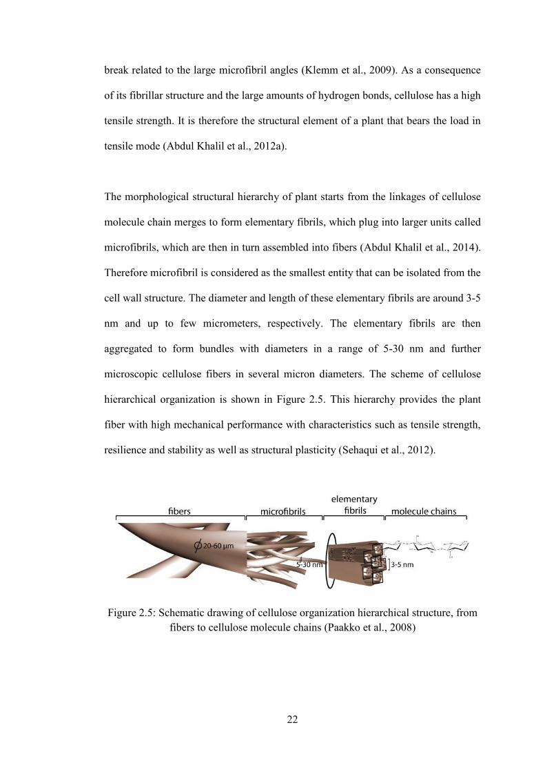
The morphological structural hierarchy of plant starts from the linkages of cellulose
molecule chain merges to form elementary fibrils, which plug into larger units called
microfibrils, which are then in turn assembled into fibers (Abdul Khalil et al., 2014).
Therefore microfibril is considered as the smallest entity that can be isolated from the
cell wall structure. The diameter and length of these elementary fibrils are around 3-5
nm and up to few micrometers, respectively. The elementary fibrils are then
aggregated to form bundles with diameters in a range of 5-30 nm and further
microscopic cellulose fibers in several micron diameters. The scheme of cellulose
hierarchical organization is shown in Figure 2.5. This hierarchy provides the plant
fiber with high mechanical performance with characteristics such as tensile strength,
resilience and stability as well as structural plasticity (Sehaqui et al., 2012).
Figure 2.5: Schematic drawing of cellulose organization hierarchical structure, from
fibers to cellulose molecule chains (Paakko et al., 2008)
23
2.2.2 Nanocellulose
Generally, ‘nanocellulose’ term is referring to cellulosic materials that at least one
dimension is in the nanometer scale, nano-size cellulose. Nanocellulose can be
extracted from various lignocelluloses material including plant, agricultural/forest
crops or residues and some bacterial (Table 2.1). There are various methods for
preparing nanocellulosic from cellulose plant fibers including chemical, mechanical
and chemo-mechanical treatment process (Abdul Khalil et al., 2012a, 2014; Ireana
Yusra et al., 2014). Acid hydrolysis as chemical treatment has been extensively
studied to isolate nanocellulose from different cellulosic sources (Fahma et al., 2010;
Qua et al., 2011; Brinchi et al., 2013).
Table 2.1: Various sources of nanocellulosic fibers (Abdul Khalil et al., 2012a)
Various sources ( Nanocellulosic fibers) References
Wood Abe et al., 2007; Chen et al., 2011
Cotton De Morais Teixeira et al., 2010
Potato tuber cells Dufresne et al., 2000
Cladodes and spines from Opuntia ficus-
indica
Malainine et al., 2003
Prickly pear fruits of Opuntia ficus-indica Habibi et al., 2008
Lemon and maize Rondeau-Mouro et al., 2003
Soybean Wang and Sain, 2007a
Wheat straw and soy hulls Alemdar and Sain, 2008
Hemp Wang and Sain, 2007b
Coconut husk Rosa et al., 2010
Branch-barks of mulberry Li et al., 2009
Pineapple leaf Cherian et al., 2010
Banana rachis Zuluaga et al., 2009
Sisal Morán et al., 2008
Pea hull Chen et al., 2009
Sugar beet Dinand et al., 1999; Dufresne et al.,
1997
Oil Palm Empty Fruit Bunch Fahma et al., 2010

24
Processes that often involve in the mechanical treatments were refining, grinding and
cryo-crushing followed by a high pressure homogenization (HPH). Usually in most
cases, the mechanically HPH process does not stand alone, when the pre-treatment
was applied together with the HPH process, it is denoted as chemo-mechanical
treatment process, a combination of chemical and mechanical treatment process (Pan
et al., 2013; Ireana Yusra et al., 2014).
Recently, nanocellulose has attracted much attention during the past few years. The
qualified characteristic for nanocellulose such as specific surface area and high
aspect ratio, high strengthening and flexibility effect, good optical and thermal
properties will find many applications in high technology and quality grade paper,
nanocomposites, coating additives, food packaging, gas barriers and etc.
(Belbekhouche et al., 2011; Moon et al., 2011). For instance, nanocellulose with
functional hydroxyl groups also allows chemical modifications for further
applications (Kaushik, 2011).
Incorporation of biodegradable, biocompatibility and non-toxicity nanocellulose as
reinforcement material in the polymer matrix has proven to be an important strategy
due to high mechanical performance and great properties in producing
nanobiocomposites for biochemical and biomedical applications (Abdul Khalil et al.,
2012a). These biodegradable nano-reinforcements also promise a great potential for
novel green nanocomposite materials development in consideration to the
environment awareness. Moreover, it has also shows potential in various
nanotechnology applications including automotive, automobile and electronic
devices industries (Abdul Khalil et al., 2014).


![0DWHULDO (6, IRU1DQRVFDOH+RUL]RQV Supporting Information … · 1 1 Supporting Information 2 High-efficiency Transfer of Fingerprints from Various Surfaces Using 3 Nanofibrillated](https://static.fdocuments.net/doc/165x107/601a5130d74c0514ef0f4b11/0dwhuldo-6-iru1dqrvfdohrulrqv-supporting-information-1-1-supporting-information.jpg)


