Characterization of P92 Steel Weldments in As-Welded and ...€¦ · Postweld heat treatment (PWHT)...
7
Introduction Creep strength enhanced ferritic (CSEF) steels are one of the important candidate materials in power plants due to excellent physical, thermal, and mechanical properties (Refs. 1, 2). The CSEF P92 steel was developed in Japan by Nippon steel (Ref. 3). P92 steel offers enhanced creep strength, which results from the combination of precipita- tion and solid-solution hardening (Refs. 4, 5). The P92 steel microstructure consists of a tempered martensitic structure that derives its stability from finely dispersed V- and Nb-rich MX (X: C, N) type precipitates inside the ma- trix region and Fe-, Cr-, and Mo-rich coarse M 23 C 6 precipi- tates along the prior austenite grain boundaries (PAGBs) (Refs. 6, 7). The optimum combination of toughness and creep strength is derived from the stable tempered martensitic microstructure (Refs. 8, 9). These fine precipi- tates helped to enhance the long-term creep rupture life of P92 steel by pinning the movement of subgrain boundaries (Ref. 10). In steam generator components, most of the failures oc- curred in the welded joints, which created the need to study welded joints (Ref. 11). During welding, the temper marten- sitic microstructure was adversely altered by the formation of fresh martensite in the weldments (weld fusion zone + heat-affected zones) (Ref. 12). During the welding process, P92 steel showed a great tendency for -ferrite formation due to the presence of ferrite stabilizers like V, Nb, W, Mo, and Cr. The presence of -ferrite patches in P92 steel welds was also observed; a negative effect on mechanical proper- ties due to notch sensitivity of the -ferrite (Refs. 13, 14). It is possible to control the formation of retained austenite and -ferrite by optimizing the base and filler metal compo- sition (Ref. 15). The high number of ferrite-forming ele- ments resulted in excessive formation of -ferrite (Ref. 16). Postweld heat treatment (PWHT) was performed to over- come the hardness gradient and temper the brittle marten- site (Ref. 17). The PWHT resulted in a great reduction in hardness, improving the ductility and toughness of the weldments (Ref. 18). Experimental Details As per the manufacturer, as-received P92 steel was sub- jected to normalized and tempered conditions. Normalizing was carried out at 1040°C for 60 min to develop the lath martensitic microstructure with high dislocation density, while tempering was performed at 760°C for 2 h for the evo- WELDING RESEARCH JULY 2018 / WELDING JOURNAL 207-s Characterization of P92 Steel Weldments in As-Welded and PWHT Conditions Room-temperature tensile tests and microhardness measurements led to improving the ductility of the weld joints BY N. SAINI, C. PANDEY, M. M. MAHAPATRA, AND R. S. MULIK ABSTRACT P92 steels have been developed as a candidate material for power plant components that operate in a temperature range of 620°–650°C. A heterogeneous microstructure for- mation across the P92 weldments makes the weldability of P92 steel a serious issue. The other problem that arises in P92 steel weldments is the formation of -ferrite due to the presence of a higher weight percentage of ferrite stabilizers such as V and Nb, as well as W and Mo. In the present work, the shielded metal arc welding (SMAW) process was utilized to prepare the P92 steel weld joints. After welding, postweld heat treatment (PWHT) was performed at 760°C for 2 h. To characterize the weld joints, room-temperature tensile tests and microhardness measurements were per- formed in the as-welded and PWHT conditions. The subse- quent PWHT resulted in a decrease in the hardness gradient across the weldments. The PWHT resulted in enhancing the ductility of the weld joints. KEYWORDS • P92 Steel • Postweld Heat Treatment (PWHT) • Hardness • -Ferrite • Tensile Properties https://doi.org/10.29391/2018.97.018 SUPPLEMENT TO THE WELDING JOURNAL, JULY 2018 Sponsored by the American Welding Society
Transcript of Characterization of P92 Steel Weldments in As-Welded and ...€¦ · Postweld heat treatment (PWHT)...

Introduction
Creep strength enhanced ferritic (CSEF) steels are oneof the important candidate materials in power plants dueto excellent physical, thermal, and mechanical properties(Refs. 1, 2). The CSEF P92 steel was developed in Japan byNippon steel (Ref. 3). P92 steel offers enhanced creepstrength, which results from the combination of precipita-tion and solid-solution hardening (Refs. 4, 5). The P92steel microstructure consists of a tempered martensiticstructure that derives its stability from finely dispersed V-
and Nb-rich MX (X: C, N) type precipitates inside the ma-trix region and Fe-, Cr-, and Mo-rich coarse M23C6 precipi-tates along the prior austenite grain boundaries (PAGBs)(Refs. 6, 7). The optimum combination of toughness andcreep strength is derived from the stable temperedmartensitic microstructure (Refs. 8, 9). These fine precipi-tates helped to enhance the long-term creep rupture life ofP92 steel by pinning the movement of subgrain boundaries(Ref. 10). In steam generator components, most of the failures oc-curred in the welded joints, which created the need to studywelded joints (Ref. 11). During welding, the temper marten-sitic microstructure was adversely altered by the formationof fresh martensite in the weldments (weld fusion zone +heat-affected zones) (Ref. 12). During the welding process,P92 steel showed a great tendency for -ferrite formationdue to the presence of ferrite stabilizers like V, Nb, W, Mo,and Cr. The presence of -ferrite patches in P92 steel weldswas also observed; a negative effect on mechanical proper-ties due to notch sensitivity of the -ferrite (Refs. 13, 14). Itis possible to control the formation of retained austeniteand -ferrite by optimizing the base and filler metal compo-sition (Ref. 15). The high number of ferrite-forming ele-ments resulted in excessive formation of -ferrite (Ref. 16).Postweld heat treatment (PWHT) was performed to over-come the hardness gradient and temper the brittle marten-site (Ref. 17). The PWHT resulted in a great reduction inhardness, improving the ductility and toughness of theweldments (Ref. 18).
Experimental Details
As per the manufacturer, as-received P92 steel was sub-jected to normalized and tempered conditions. Normalizingwas carried out at 1040°C for 60 min to develop the lathmartensitic microstructure with high dislocation density,while tempering was performed at 760°C for 2 h for the evo-
WELDING RESEARCH
JULY 2018 / WELDING JOURNAL 207-s
Characterization of P92 Steel Weldments in As-Welded and PWHT Conditions
Room-temperature tensile tests and microhardness measurements led to improving the ductility of the weld joints
BY N. SAINI, C. PANDEY, M. M. MAHAPATRA, AND R. S. MULIK
ABSTRACT P92 steels have been developed as a candidate materialfor power plant components that operate in a temperaturerange of 620°–650°C. A heterogeneous microstructure for-mation across the P92 weldments makes the weldability ofP92 steel a serious issue. The other problem that arises inP92 steel weldments is the formation of -ferrite due to thepresence of a higher weight percentage of ferrite stabilizerssuch as V and Nb, as well as W and Mo. In the presentwork, the shielded metal arc welding (SMAW) process wasutilized to prepare the P92 steel weld joints. After welding,postweld heat treatment (PWHT) was performed at 760°Cfor 2 h. To characterize the weld joints, room-temperaturetensile tests and microhardness measurements were per-formed in the as-welded and PWHT conditions. The subse-quent PWHT resulted in a decrease in the hardness gradientacross the weldments. The PWHT resulted in enhancing theductility of the weld joints.
KEYWORDS • P92 Steel • Postweld Heat Treatment (PWHT) • Hardness • -Ferrite • Tensile Properties
https://doi.org/10.29391/2018.97.018
SUPPLEMENT TO THE WELDING JOURNAL, JULY 2018Sponsored by the American Welding Society
SAINI ET AL 2017103 SUPP JULY 2018.qxp_Layout 1 6/6/18 11:32 AM Page 207

lution of precipitates that provide the microstructure stabil-ity. The chemical compositions of as-received plates andfiller rod are depicted in Table 1. The plates sized 150 60 12 mm were prepared fromas-received plates. A V-groove was produced for makingweld joints. The root height and groove angle were takenas 1.5 mm and 37.5 deg, respectively. Shielded metal arcwelding (SMAW) was utilized to produce P92 steel weldjoints. The P92 steel filler rod (flux coated, 4 mm diame-ter) was used with a welding current of 140 A and arc volt-age in the range of 23–26 V. Before welding, preheatingwas performed at a temperature of 300°C using flameheating. Before PWHT, the postweld heating was also per-formed at 250°C for 40 min to remove the diffusible hy-drogen content (Ref. 19). After the postweld heating, postweld heat treatment(PWHT) was performed at 760°C for 2 h. To characterizethe sample, shaping, grinding, paper polishing, and clothpolishing were performed. After polishing, samples wereetched in Vilella’s reagent. Samples were characterized us-ing a field-emission scanning electron microscope (FES-EM), microhardness tester (Omnitech S. Auto), and verti-cal tensile testing machine (Instron:5982) techniques. Ac-cording to ASTM E8/E8M, the transverse flat subsize ten-sile specimens were prepared with a gauge width of 6 mmand gauge length of 25 mm (Ref. 20). Room-temperaturetensile tests were performed at a constant cross-headspeed of 1 mm/min. In addition, a Vicker’s microhardnesstester was used for the hardness measurement at a 500-gload and dwell time of 10 s.
Results and Discussion
As-Received Material
The micrographs of P92 steel in low and high magnifica-tions are shown in Fig. 1A and B, respectively. The low magni-fication micrograph consists of PAGBs with packets, laths,packet boundaries, and blocks of laths, as shown in Fig. 1A.The distribution and morphology of coarse M23C6-type precipi-tates and fine MX precipitates at lath boundaries and PAGBswere clearly seen at higher magnification, as shown in Fig. 1B.Evolution of precipitates along PAGB, lath blocks, packetboundaries, and inside intra lath region is shown in schematicdiagram of Fig. 1C. It defines the lath boundaries, packetboundaries, packet, columnar laths, PAGBs, coarse M23C6 pre-cipitates, and fine MX precipitates. The ultimate tensilestrength (UTS), % elongation, microhardness, and impacttoughness of as-received P92 steel were measured as 678 ± 10MPa, 23 ± 2%, 227 ± 4 HV, and 198 ± 8 J, respectively.
Characterization of Weldments
Figure 2A shows the weld joint after welding completion.The optimized base material microstructure was changedcompletely by an applied welding cycle. Based on tempera-ture experience, the P92 weldments are divided into theweld fusion zone and narrow heat-affected zones (HAZs).Narrow HAZs show the continuous microstructure changedue to the varying temperature range, and it is divided intocoarse grain (CG), fine grain (FG), intercritical (IC), and
WELDING RESEARCH
WELDING JOURNAL / JULY 2018, VOL.97208-s
Table 1 — Chemical Compositions of As-Received Materials, Wt-%
Element C Mn P S Si Cr Mo V Al Nb W Cu Ni N Fe
Base 0.10 0.58 0.007 0.003 0.48 9.09 0.42 0.24 0.02 0.07 1.86 0.03 0.30 0.02 Rest Filler 0.11 0.60 0.008 0.005 0.19 8.90 0.45 0.22 — 0.06 1.82 0.04 0.35 0.06 Rest
Fig. 1 — Microstructure of the following: A and B — As-receivedP92 steel; and C — schematic of a prior austenite grain.
Fig. 2 — A — Schematic of the welding passes; B — com-plete weld joint; and C — cross section of the weld joint.
AA
C
B
C
B
SAINI ET AL 2017103 SUPP JULY 2018.qxp_Layout 1 6/6/18 11:32 AM Page 208

overtempered base material. The P92 steel weld showing theweld fusion zone, various zones formed in the HAZ, and fea-tures of the weld are shown in Fig. 2B. A typical untempered columnar lath microstructure ofthe weld fusion zone is shown in Fig. 3A. The microstruc-ture also shows the -ferrite. In P92 steel, a high weight per-centage of ferrite stabilizer elements like W and Mo pro-mote -ferrite formation. In P92 steel weldments, the pres-ence of -ferrite was undesired with respect to poor weldtoughness. The zone adjacent to the weld fusion zone expe-rienced temperatures much above the transformation tem-perature (Ac3) and denoted as coarse grain heat-affectedzone (CGHAZ). The dissolution of precipitates occurred atsuch a high temperature, which resulted in a higher amountof carbon (C) and nitrogen (N) in the solid-solution matrix.The pinning force by the precipitates was also reduced dueto dissolution of precipitates, which resulted in formation ofcoarse grains of austenite. Hence, in the as-welded condi-tion, coarse grain lath martensitic structure was observed inthe CGHAZ, as shown in Fig. 3B. The fine grain heat-affect-ed zone (FGHAZ) experienced a temperature just above Ac3. Fewer coarse M23C6 and fine MX precipitates remainundissolved because the temperature was not capable of dissolving the precipitates completely, as shown in Fig. 3C.
The size of coarse M23C6 was observed to be varied from 574to 723 nm with an average precipitate size of 638 ± 62 nm.The fine MX precipitates are difficult to resolve using theSEM micrographs. The growth of austenite grain impededby these undissolved precipitates resulted in the fine prioraustenite grains (PAGs) structure. Some -ferrite patcheswere also observed in the FGHAZ. In P92 steel weldments,the mild intercritical heat-affected zone (ICHAZ) was foundto be an interesting region, which had a mixed combinationof new prior austenite grains and remaining coarse tem-pered grains, with some undissolved precipitates and coarsetempered precipitates, as shown in Fig. 3D. In the PWHT condition, evolution of dissolved precipi-tates occurs. After PWHT, the microstructural evolution anddistribution of carbide precipitates in the weldments areshown in Fig. 4A–D. The PWHT of P92 weldments lead tothe evolution of precipitates and coarsening of existing pre-cipitates. Evolution of precipitates and coarsening of exist-ing precipitates in every zone of P92 steel weldments isshown in Fig. 4A–D. The PWHT results in overtempering ofthe base metal. The overtempering does not contribute somuch in microstructural change. Overtempering does notallow the phase change, but it leads to negligible coarseningof M23C6-type carbide precipitates.
WELDING RESEARCH
JULY 2018 / WELDING JOURNAL209-s
Fig. 3 — Secondary electron micrographs in the as-welded condition: A — Weld fusion zone; B — CGHAZ; C — FGHAZ; and D — ICHAZ.
A B
C D
SAINI ET AL 2017103 SUPP JULY 2018.qxp_Layout 1 6/6/18 11:32 AM Page 209
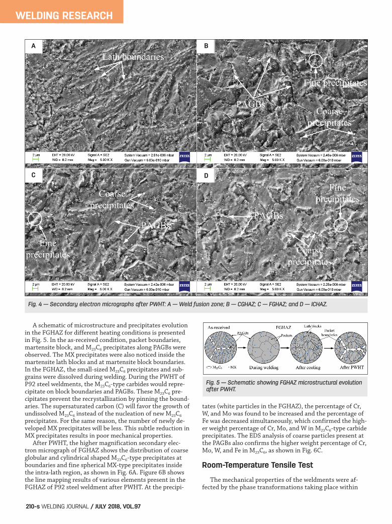
A schematic of microstructure and precipitates evolutionin the FGHAZ for different heating conditions is presentedin Fig. 5. In the as-received condition, packet boundaries,martensite block, and M23C6 precipitates along PAGBs wereobserved. The MX precipitates were also noticed inside themartensite lath blocks and at martensite block boundaries.In the FGHAZ, the small-sized M23C6 precipitates and sub-grains were dissolved during welding. During the PWHT ofP92 steel weldments, the M23C6-type carbides would repre-cipitate on block boundaries and PAGBs. These M23C6 pre-cipitates prevent the recrystallization by pinning the bound-aries. The supersaturated carbon (C) will favor the growth ofundissolved M23C6 instead of the nucleation of new M23C6
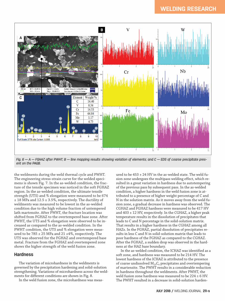
precipitates. For the same reason, the number of newly de-veloped MX precipitates will be less. This subtle reduction inMX precipitates results in poor mechanical properties. After PWHT, the higher magnification secondary elec-tron micrograph of FGHAZ shows the distribution of coarseglobular and cylindrical shaped M23C6-type precipitates atboundaries and fine spherical MX-type precipitates insidethe intra-lath region, as shown in Fig. 6A. Figure 6B showsthe line mapping results of various elements present in theFGHAZ of P92 steel weldment after PWHT. At the precipi-
tates (white particles in the FGHAZ), the percentage of Cr,W, and Mo was found to be increased and the percentage ofFe was decreased simultaneously, which confirmed the high-er weight percentage of Cr, Mo, and W in M23C6-type carbideprecipitates. The EDS analysis of coarse particles present atthe PAGBs also confirms the higher weight percentage of Cr,Mo, W, and Fe in M23C6, as shown in Fig. 6C.
Room-Temperature Tensile Test
The mechanical properties of the weldments were af-fected by the phase transformations taking place within
WELDING RESEARCH
WELDING JOURNAL / JULY 2018, VOL.97210-s
Fig. 4 — Secondary electron micrographs after PWHT: A — Weld fusion zone; B — CGHAZ; C — FGHAZ; and D — ICHAZ.
Fig. 5 — Schematic showing FGHAZ microstructural evolutionafter PWHT.
A B
C D
SAINI ET AL 2017103 SUPP JULY 2018.qxp_Layout 1 6/6/18 11:32 AM Page 210
the weldments during the weld thermal cycle and PWHT.The engineering stress-strain curve for the welded speci-mens is shown Fig. 7. In the as-welded condition, the frac-ture of the tensile specimen was noticed in the soft FGHAZregion. In the as-welded condition, the ultimate tensilestrength (UTS) and % elongation were measured to be 674± 18 MPa and 12.5 ± 3.5%, respectively. The ductility ofweldments was measured to be lowest in the as-weldedcondition due to the high volume fraction of untemperedlath martensite. After PWHT, the fracture location wasshifted from FGHAZ to the overtempered base zone. AfterPWHT, the UTS and % elongation were observed to be in-creased as compared to the as-welded condition. In thePWHT condition, the UTS and % elongation were meas-ured to be 785 ± 25 MPa and 21 ±4%, respectively. TheUTS was observed for the FGHAZ and overtempered basemetal. Fracture from the FGHAZ and overtempered zoneshows the higher strength of the weld fusion zone.
Hardness
The variation of microhardness in the weldments is governed by the precipitation hardening and solid-solutionstrengthening. Variations of microhardness across the weld-ments for different conditions are shown in Fig. 8. In the weld fusion zone, the microhardness was meas-
ured to be 453 ± 24 HV in the as-welded state. The weld fu-sion zone undergoes the multipass welding effect, which re-sulted in a great variation in hardness due to autotemperingof the previous pass by subsequent pass. In the as-weldedcondition, a higher hardness in the weld fusion zone is at-tributed to a presence of higher weight percentage of C andN in the solution matrix. As it moves away from the weld fu-sion zone, a gradual decrease in hardness was observed. TheCGHAZ and FGHAZ hardness were measured to be 417 HVand 403 ± 12 HV, respectively. In the CGHAZ, a higher peaktemperature results in the dissolution of precipitates thatleads to C and N percentage in the solid-solution matrix.That results in a higher hardness in the CGHAZ among allHAZs. In the FGHAZ, partial dissolution of precipitates re-sults in less C and N in solid-solution matrix that leads topoor hardness of the FGHAZ as compared to the CGHAZ.After the FGHAZ, a sudden drop was observed in the hard-ness at the HAZ base boundary. In the as-welded condition, the ICHAZ was identified as asoft zone, and hardness was measured to be 214 HV. Thelowest hardness of the ICHAZ is attributed to the presenceof coarse undissolved M23C6 precipitates and overtemperingof martensite. The PWHT results in a considerable reductionin hardness throughout the weldments. After PWHT, theweld fusion zone hardness was measured to be 224 ± 6 HV.The PWHT resulted in a decrease in solid-solution harden-
WELDING RESEARCH
JULY 2018 / WELDING JOURNAL 211-s
Fig. 6 — A — FGHAZ after PWHT; B — line mapping results showing variation of elements; and C — EDS of coarse precipitate pres-ent on the PAGB.
A
B
C
SAINI ET AL 2017103 SUPP JULY 2018.qxp_Layout 1 6/6/18 11:32 AM Page 211

ing, but at the same time, the evolution of precipitates leadsto precipitation hardening. In the PWHT condition, a reduc-tion in solid-solution hardening was observed to be domi-nated over the increase in precipitation hardening that re-sulted in a decrease in the hardness of the weldments. Theaverage hardness of CGHAZ and FGHAZ was measured to be219 and 205 ± 10 HV, respectively. However, the soft ICHAZzone still observed in the welded joints leads to poor creepstrength of the P92 steel weldments.
Conclusions
The following conclusions can be made: • The microstructures of P92 steel weldments were char-acterized by the untempered lath martensite, lath packets,lath boundaries, and -ferrite. • After PWHT, the strength and ductility were increased.In the PWHT condition, it was observed that the fracture lo-cation was shifted to overtempered base metal from the FGHAZ after the room-temperature tensile test. • The microhardness of subzones of the P92 weldmentsshowed the great heterogeneity in the microstructure. Maxi-mum and minimum hardness were measured to be 453 ± 24,and 214 HV for weld fusion zone and ICHAZ, respectively.After PWHT, a considerable softening was noticed in eachzone of the P92 steel weldments.
1. Coussement, C., Dhooge, A., de Witte, M., Dobbelaere, R.,and van der Donckt, E. 1991. High temperature properties of im-proved 9% Cr steel weldments. Int. J. Press. Vessel. Pip. 45: 163–178. DOI: doi.org/10.1016/0308-0161(91)90090-O. 2. Wang, S. S., Peng, D. L., Chang, L., and Hui, X. D. 2013. En-hanced mechanical properties induced by refined heat treatmentfor 9Cr–0.5Mo–1.8W martensitic heat resistant steel. Mater. Des.50: 174–180. DOI: doi.org/10.1016/j.matdes.2013.01.072. 3. Sakthivel, T., Laha, K., Parameswaran, P., Panneer Selvi, S.,and Chandravathi, K. S. 2015. Effect of thermal aging on mi-crostructure and mechanical properties of P92 steel. Trans. IndianInst. Met. 68: 411–421. DOI: doi.org/10.1007/s12666-014-0480-x.
4. Dudko, V., Belyakov, A., and Kaibyshev, R. 2016. Origin ofthreshold stresses in a P92-type steel. Trans. Indian Inst. Met. 69:223–227. DOI: doi.org/10.1007/s12666-015-0757-8. 5. Maruyama, K., Sawada, K., and Koike, J. 2001. Strengtheningmechanisms of creep resistant tempered martensitic steel. ISIJ Int.41: 641–653. 6. Barbadikar, D. R., Deshmukh, G. S., Maddi, L., Laha, K., Para-meswaran, P., Ballal, A. R., Peshwe, D. R., Paretkar, R. K.,Nandagopal, M., and Mathew, M. D. 2015. Effect of normalizingand tempering temperatures on microstructure and mechanicalproperties of P92 steel. Int. J. Press. Vessel. Pip. 132–133: 97–105.DOI: doi.org/10.1016/j.ijpvp.2015.07.001. 7. Sklenicka, V., Kucharova, K., Svobodová, M., Kvapilová, M.,Král, P., and Horváth, L. 2016. Creep properties in similar weldjoint of a thick-walled P92 steel pipe. Mater. Charact. 119: 1–12.DOI: doi.org/10.1016/j.matchar.2016.06.033. 8. Saini, N., Pandey, C., Mahapatra, M. M., Narang, H. K., Mulik, R.S., and Kumar, P. 2017. A comparative study of ductile-brittle transi-tion behavior and fractography of P91 and P92 steel. Eng. Fail. Anal.:245–253. DOI: doi.org/10.1016/j.engfailanal.2017.06.044. 9. Saini, N., Pandey, C., and Mahapatra, M. M. 2017. Characteri-zation and evaluation of mechanical properties of CSEF P92 steelfor varying normalizing temperature. Mater. Sci. Eng. A 688: 250–261. DOI: doi.org/10.1016/j.msea.2017.02.022. 10. Shrestha, T., Alsagabi, S. F., Charit, I., Potirniche, G. P., andGlazoff, M. V. 2015. Effect of heat treatment on microstructureand hardness of Grade 91 Steel. Metals 5: 131–149. DOI:10.3390/met5010131. 11. Sambamurthy, E., Dutta, S., Panda, A. K., Mitra, A., andRoy, R. K. 2014. Evaluation of post-weld heat treatment behaviorin modified 9Cr-1Mo steel weldment by magnetic Barkhausenemission. Int. J. Press. Vessel. Pip. 123–124: 86–91. DOI:doi.org/10.1016/j.ijpvp.2014.08.004. 12. Pandey, C., Giri, A., Mahapatra, M. M., and Kumar, P. 2017.Characterization of microstructure of HAZs in as-welded and serv-ice condition of P91 pipe weldments. Met. Mater. Int. 23: 148–162.DOI: doi.org/10.1007/s12540-017-6394-5. 13. Onoro, J. 2006. Weld metal microstructure analysis of 9-12% Cr steels. Int. J. Press. Vessel. Pip. 83: 540–545. DOI:doi.org/10.1016/j.ijpvp.2006.03.005. 14. Cai, G., Svensson, L., and Andren, H. 1997. Effect of coolingafter welding on microstructure and mechanical properties of 12Pct Cr steel weld metals. Metall. Mater. Trans. A 28A: 1417–1428.DOI: doi.org/10.1007/s11661-997-0204-5. 15. Abson, D. J., and Rothwell, J. S. 2013. Review of type IV crack-
WELDING RESEARCH
WELDING JOURNAL / JULY 2018, VOL.97212-s
Fig. 7 — Engineering stress-strain curve for various tensiletested specimens. Fig. 8 — Hardness variation across the weldments.
References
SAINI ET AL 2017103 SUPP JULY 2018.qxp_Layout 1 6/6/18 11:32 AM Page 212
ing of weldments in 9 – 12 % Cr creep strength enhanced ferriticsteels. Int. Mater. Rev. 58: 437–473. DOI: doi.org/10.1179/1743280412Y.0000000016. 16. Mandziej, S. T., Výrostková, A., and Chovet, C. 2011. Mi-crostructure and creep rupture of P92-grade weld metal. Weld.World 55: 37–51. DOI: doi.org/10.1007/BF03321294. 17. Xue, W., Qian-gang, P., Yao-yao, R., Wei, S., Hui-qiang, Z.,and Hong, L. 2012. Microstructure and type IV cracking behaviorof HAZ in P92 steel weldment. Mater. Sci. Eng. A 552: 493–501.DOI: doi.org/10.1016/j.msea.2012.05.076. 18. Dodo, M. R., Ause, T., Adamu, M. A., and Ibrahim, Y. M. 2016.Effect of post-weld heat treatment on the microstructure and me-chanical properties of arc welded medium carbon steel. Niger. J. Tech-nol. 35: 337–343. DOI: http://dx.doi.org/10.4314/njt.v35i2.14. 19. Pandey, C., and Mahapatra, M. M. 2016. Effect of heat treatment on microstructure and hot impact toughness of various
zones of P91 welded pipes. J. Mater. Eng. Perform. 25: 2195–2210.DOI: doi.org/10.1007/s11665-016-2064-x. 20. ASTM-E8/E8M. 2017. Standard Test Methods and Definitionsfor Mechanical Testing of Steel Products, pp. 1–49. DOI: 10.1520/A0370-17.2.
WELDING RESEARCH
JULY 2018 / WELDING JOURNAL 213-s
NITIN SAINI ([email protected]), CHANDAN PANDEY, andRAHUL S. MULIK are with the Department of Mechanical andIndustrial Engineering, Indian Institute of Technology Roorkee,Uttrakhand, India. MANAS MOHAN MAHAPATRA is with theSchool of Mechanical Sciences, Indian Institute of Technol-ogy, Bhubaneswar, Odisha, India.
Peer review of research papers is now managedthrough an online system using Editorial Manager soft-ware. Papers can be submitted into the system directlyfrom the Welding Journal page on the AWS website(aws.org) by clicking on “submit papers.” You can also ac-cess the new site directly at editorialmanager.com/wj/.Follow the instructions to register or log in. This onlinesystem streamlines the review process, and makes it eas-ier to submit papers and track their progress. By pub-
lishing in the Welding Journal, more than 70,000 mem-bers will receive the results of your research. Additionally, your full paper is posted on the AmericanWelding Society website for FREE access around theglobe. There are no page charges, and articles are pub-lished in full color. By far, the most people, at the leastcost, will recognize your research when you publish in theworld-respected Welding Journal.
Authors: Submit Research Papers Online
Welding Journal Now Publishing Direct Object Identifier (DOI) Numbers
Dear members of the welding research community,
Note that in each issue of the Welding Journal Research Supplement, we are including Direct Object Identifier(DOI) numbers with each of the papers published in print and online. (We have also backnumbered the paperspublished in the January and February 2018 issues.) A direct object identifier is a unique alphanumeric string as-signed by a registration agency (we are using Crossref.org) to identify content and provide a persistent link to itslocation on the Internet. Our decision to begin assigning a DOI for each paper comes directly from a request bythe research community.
As part of our obligation to Crossref.org, we are asked to provide DOI numbers, when available, in the referencessection of papers. So, if you have submitted a paper to the Welding Journal or are planning on submitting a paper,we ask that you update your references to include DOI numbers whenever possible.
Thank you.
Mary Ruth Johnsen, Publisher, Welding Journal
SAINI ET AL 2017103 SUPP JULY 2018.qxp_Layout 1 6/6/18 11:32 AM Page 213