Soft x-ray spectroscopies: Photoemission and x-ray absorption

Characteristics of materialsstructure by the X-ray diffraction
INature and sources of the X-rays
Internet survey of the lectures: http://imim.pl/studium-doktoranckie-imim-pan-uj/materiay-do-wykadow
1. Nature and sources of the X-rays
2. Diffraction phenomenon of X-ray
3. Crystallography and diffraction
4. Crystallographic texture
5. X-Ray Texture Tomography
6. Texture analysis of polycrystalline materials
7. X-ray diffraction techniques in materials engineering – measurements of the first order stresses
8. X-ray phase analysis, other useful methods and the newest achievements in the field of XRD
9. Demonstration of experimental set up and measurement procedures in the X-ray Laboratory

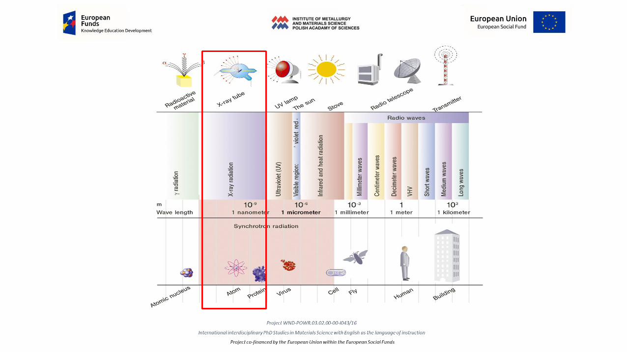
Electromagnetic radiation (electromagnetic wave)
Disturbance of the electromagnetic field in space. The electrical and magnetic components of the waves are induced by each other - a changing electric field produces a changing magnetic field, and a changing magnetic field produces a changing electric field. The properties of electromagnetic waves depend on the wavelength.
In the quantum description, electromagnetic radiation is treated as a massless stream of elementary particles called photons. The energy of each photon depends on the wavelength.
One of the most difficult issues of modern science...

Characteristics of electromagnetic waves:Electromagnetic waves do not require the presence of a medium and may also propagate in a vacuum.Electromagnetic waves propagate in a vacuum at a constant speed of c=299 792 458 m/s. In material medium, this speed is always lower (equal to c/n, where n - refractive index) and depends on the type of medium and the frequency of the wave.
Like any mechanical wave, electromagnetic wave is characterized by:• frequency ν, number of complete changes of magnetic and
electric fields per second, expressed in Hertz (Hz),• period of variation T, defined as the inverse of the frequency:
T=1/ν, i.e. the time during which the return to the same phase of the electric and magnetic field occurs,
• wavelength λ, which is the distance between adjacent points at which the electric and magnetic fields have the same phase.
These values are interrelated: the higher the frequency, the shorter the wavelength (ν=c/λ).

Visible rangeof light as
electromagneticradiation
Electromagnetic waves propagate in a vacuum at a constant speed of c=299 792 458 m/s. In material medium, this speed is always lower (equal to c/n, where n - refractive index) and depends on the type of medium and the frequency of the wave.

Electromagnetic wave is not the only possible description of electromagnetic radiation. This radiation can also be treatedas a stream of small portions of energy (quantums), called photons. To describe the movement of particles we use sizessuch as momentum and particle energy, not wavelength or frequency. There must therefore be a close relationshipbetween the quantities describing the particle and the wave. According to de Broglie's accounts, a single photon carries
energy E=hν=hc/λ and momentum p=hν/c=h/λ.
The photon described in this way is a particle without mass! A constant h is a constant of nature, called the Planckconstant, h=6.626-10-34 J-s. It is not clear why electromagnetic wave in some phenomena shows a wave nature(reflection, refraction, interference, diffraction, polarization), and in others a corpuscular nature (photoelectric effect,Compton phenomenon). The duality of the nature of electromagnetic radiation is called corpuscular-wave dualism and itshould be attributed rather to the lack of our conceptual apparatus, which is forced to transfer its images created incontact with the macro-world to microscopic phenomena. The wave image describes sufficiently well the propagation ofradio waves (large wavelengths), but light phenomena already require the use of two descriptions. The higher thefrequency of electromagnetic radiation (lower wavelength), the stronger the corpuscular effects and the necessarycorpuscular description. The nature of electromagnetic radiation is currently explained by quantum electrodynamics.

Nature and sources
of
X radiation

Bibliography
o Bojarski, Z., Łągiewka, E. (1988). Rentgenowska analiza strukturalna, PWN, Warszawa.o Bonarski, J. (2001). Rentgenowska Tomografia Teksturowa, IMIM PAN, Kraków.o Bunge, H.J. (1982). Texture Analysis in Materials Science. Mathematical Methods. Butterworths Publ. London.o James, R.W. (1954). The Optical Principles of the Diffraction of X-Rays. London: Bell and Sons Ltd.o Cullity, B.D. (1978). Elements of X-Ray Diffraction. 2nd Ed., Addison Waseley Publ.Comp.Inc., London, Amsterdam, Don
Mills, Sydney, Podstawy dyfrakcji promieni rentgenowskich. tłum z j. ang., PWN (1964), Warszawa.o LaboTex. (2000). The Texture Analysis Software. by LaboSoft s.c. o Luger, P. (1989). Rentgenografia strukturalna monokryształów. PWN Warszawa, tłum. Z ang. Ed. by Walter de Gruyter, Berlin
- New York, Modern X-Ray Analysis on Single Crystalso Przedmojski, J. (1990). Rentgenowskie metody badawcze w inżynierii materiałowej, WNT. Warszawa.o Sonin, A.S. (1982). O krystalografii, PWN, Warszawa.
• Chateigner D. (2006), Combined Analysis: structure-texture-microstructure-phase-stresses-reflectivity determination by x-ray and neutron scattering, CRISMAT-ENSICAEN, UMR CNRS n⁰6508, 6Bd. M.Juin, F-14050 Caen, France.
• Mittemeijer E.J., Scardi P. (Eds.), (2004) Diffraction Analysis of the Microstructure of Materials, Springer-Verlag Berlin Heidelberg 2004.

Wilhelm Conrad RÖNTGEN (1845 – 1923) Germany
Received the first Nobel Prize for Physics, in 1901. Earlier in 1895
when experimenting with a cathode-ray tube, he noticed that some
nearby barium platinocyanide fluoresced. So he proposed that an
unknown type of radiation (X-ray) was produced.

Industrial
radiographyoperational safety,
quality control
Public securityilumination of
passangers/baggage,
terrorism prevention
Diffractometryrecognizing the internal
structure of matter
Sterilisationmedical tools/materials
X-ray Astronomyobservation of universum
Neutralization of
electrostatic chargesin manufacturing the paper and
plastics
X-ray litographypatterns on Si-plates
Metrologythickness of coatings, keeping the
horizontal level
Scientific researchmodification of genetic structure by
irradiation
Spectrometryidentification of chemical
composition
Medical diagnostic/therapyhuman/animal treating,
life elongation/comfort
Investigation of fast
phenomenaflash inspection in synchrotron
Usageof
X-raysFood productiondetection of forein bodies,
preservation
Archeologynon-destructive inspection
of historic objects

Sources of X-radiation
X-ray tubetraditional way of inducing the X-radiation
(X-rays can be generated by an X-ray tube, a vacum tube that uses a high voltage to accelerate the electrons releasedby a hot cathode to a high velocity. The high velocity electrons collide with a metal target, the anode, creating the X-rays. In medical X-ray tubes the target is usually tungsten or a more crack-resistant alloy of rhenium (5%) andtungsten (95%), but sometimes molybdenum for more specialized applications, such as when softer X-rays areneeded as in mammography. In crystallography, a copper target is most common, with cobalt often being usedwhen fluorescence from iron content in the sample might otherwise present a problem.)
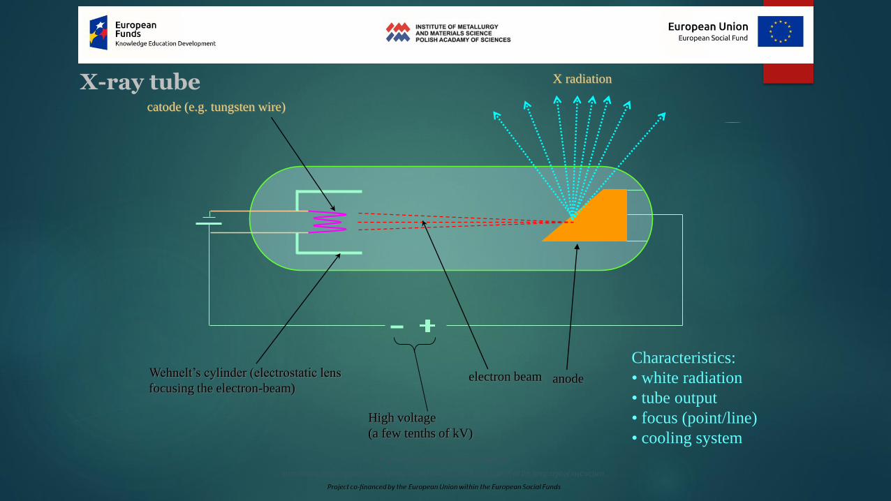
X-ray tube X radiation
catode (e.g. tungsten wire)
Wehnelt’s cylinder (electrostatic lens
focusing the electron-beam)electron beam anode
High voltage
(a few tenths of kV)
Characteristics:
• white radiation
• tube output
• focus (point/line)
• cooling system

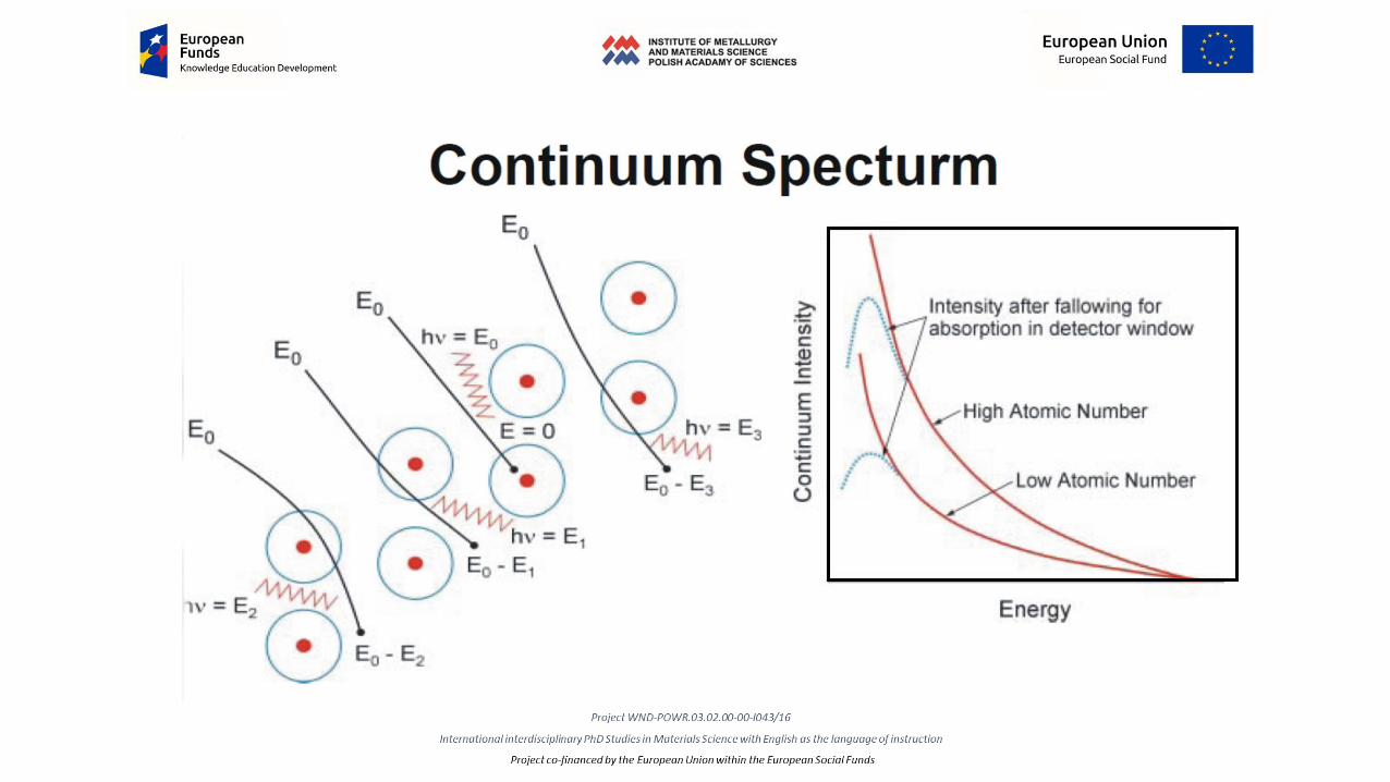
The maximum energy of the produced X-ray is limited by the energy of the incident electron, which is equalto the voltage on the tube times the electron chargé.
When the electrons hit the target, X-rays are created by two different atomic processes:• Characteristic X-ray emission: If the electron has enough energy it can knock an orbital electron out of the
inner electron shell of a metal atom, and as a result electrons from higher energy levels then fill up thevacancy and X-ray photons are emitted. This process produces an emission spectrum of X-rays at a fewdiscrete frequencies, sometimes referred to as the spectral lines. The spectral lines generated depend on thetarget (anode) element used and thus are called characteristic lines. Usually these are transitions from uppershells into K shell (called K lines), into L shell (called L lines) and so on.
• Bremsstrahlung: This is radiation given off by the electrons as they are scattered by the strong electric fieldnear the high-Z (proton number) nuclei. These X-rays have a continuous spectrum. The intensity of the X-rays increases linearly with decreasing frequency, from zero at the energy of the incident electrons, thevoltage on the X-ray tube.


Quantum numbers
The principal quantum number (symbolized n) is assigned to each electron in an atom to describe that electron's state. As a discretevariable, the principal quantum number is always an integer. As n increases, the number of electronic shells increases and the electronspends more time farther from the nucleus. As n increases, the electron is also at a higher potential energy and is therefore less tightlybound to the nucleus.
The azimuthal quantum number is a quantum number for an atomic orbital that determines its orbital angular momentum anddescribes the shape of the orbital. The azimuthal quantum number is the second of a set of quantum numbers which describe theunique quantum state of an electron. It is also known as the orbital angular momentum quantum number, orbital quantumnumber or second quantum number, and is symbolized as ℓ.
The magnetic quantum number is the third of a set of quantum numbers which describe the unique quantum state of an electron andis designated by the letter m. The magnetic quantum number denotes the energy levels available within a subshell. This quantumnumber indicates the possible orientation of orbital in space. The value of 'm' for a particular value of 'l' varies from +l to -l includingzero.
The spin quantum number is a quantum number that parameterizes the intrinsic angular momentum (or spin angular momentum, orsimply spin) of a given particle. The spin quantum number is the fourth of a set of quantum numbers which describe theunique quantum state of an electron and is designated by the letter s. It describes the energy, shape and orientation of orbitals.

Electron configuration of Cu-atom:
1s22s2p63s2p6d104s1
K L M1s2
2s2
2p2
2p4
3s2
3p2
3p4
3d6
3d4
n (1, 2, 3…) The principal quantum number(reflects the complete wave length of the electron on its orbit with r-
radius) using to estimate the electron energy.
4s1
N
l (s, p, d…) The azimuthal quantum numer (introduced for non-circular orbits) reflects the orbital moment of
momentum: s - relates to l = 0, p – to l = 1, d – to l = 2,...). l = 0, 1, 2, 3… n-1
Additional two quantum numbers m and s are required for a complete description of the electron state in the atom:
m The magnetic quantum number regards a various orientation of the orbital which corresponds to specific
movement state: m = -l, (-l+1), …, 0, +1, +2, …, +l.
s - The spin quantum number of electrons: s = ±½
Quantum numbers describing the electron configuration are the result of description its movement by a wave equation.
Non-zero solution (non-zero amplitude of electron) in the wave equation for the electron needs a complete number of its
wave length for the defined orbit. For that reason the sequential numbers (quantum numbers) accurating the orbitals have
been introduced: e.g. ……….. 8 states (2-”s” and 6-”p”) for the electron quantum number n = 2,
……… 18 states (2-”s”, 6-”p” and 10-”d”) for the electron quantum number n = 3, and so on.
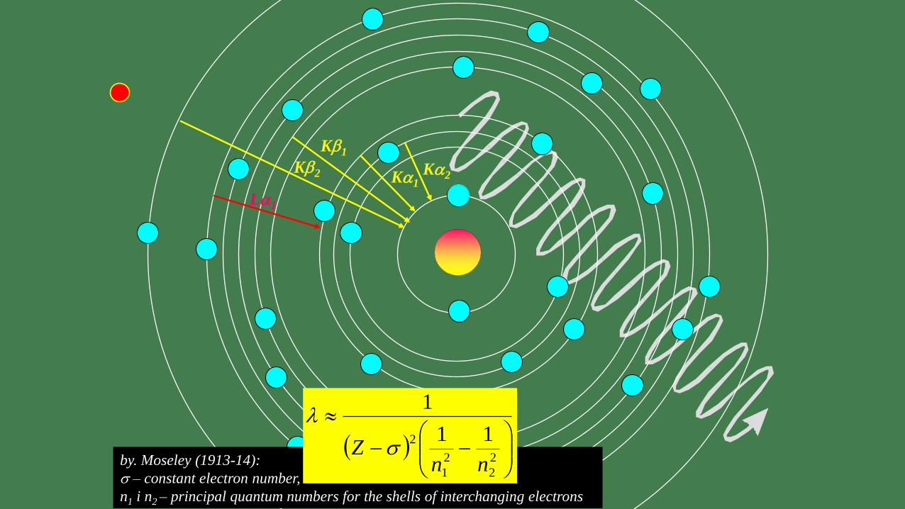
Ka1
by. Moseley (1913-14):
s – constant electron number,
n1 i n2 – principal quantum numbers for the shells of interchanging electrons
Ka2
Kb1
Kb2
La1
2
2
2
1
2 11
1
nnZ s

High voltave
Characteristics:
• white radiation (Bremsstrahlung)
• tube output (actual)
• focus (point/line)
• cooling system
2
2
1mveVelektronofenerykinetic
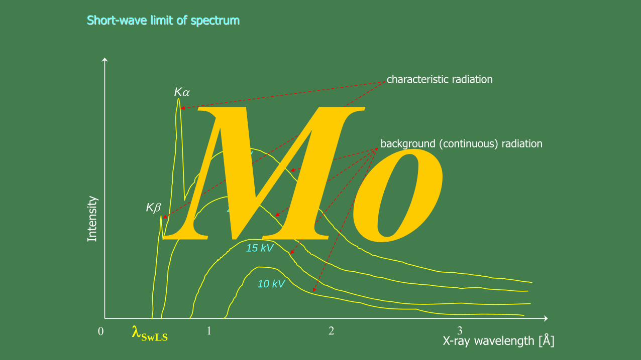
Short-wave limit of spectrum
Inte
nsi
ty
X-ray wavelength [Å]
Kb
background (continuous) radiation
0
Kacharacteristic radiation
1 2 3SwLS
25 kV
20 kV
10 kV
15 kV
X-rays can also be produced by fast protons or other positive ions. The proton-induced X-ray emission or particle-induced X-ray emission is widely used as an analytical procedure. For high energies, the production cross section is proportionalto Z1
2Z2−4, where Z1 refers to the atomic numer of the ion, Z2 to that of the target atom.
Particle-induced X-ray emission or proton-induced X-ray emission (PIXE) is a technique used in the determining ofthe element make-up of a material or sample. When a material is exposed to an ion beam, atomic interactions occur thatgive off EM radiation of wavelenghts in the x-ray part of the electromagnetic spectrum specific to an element. PIXE is apowerful yet non-destructive elemental analysis technique now used routinely by geologists, archaeologists, artconservators and others to help answer questions of provenance, dating and authenticity.
MicroPIXE allows protein analysis. The advantage of microPIXE is that given a protein of known sequence, the X-rayemission from sulfur can be used as an internal standard to calculate the number of metal atoms per protein monomer. Therelative concentrations of DNA to protein (and metals) can also be measured using the phosphate groups of the bases as aninternal calibration.

Synchrotron radiationGeneration of synchrotron radiation
The synchrotron was originally built for nuclear physics. In such a device, electrons or other particles are accelerated on acircular track, the circumference of which is often hundreds of metres. The curvature of the particle path is carried out by avertically oriented magnetic field of the electromagnets. The deviation of the track from the straight line is accompaniedby the emission of electromagnetic radiation. In past, this radiation was considered to be a necessary evil and appropriateshielding needed to be built against it.
The first devices working for solid state physics were properly adapted synchrotrons. However, the solutions applied so farproved to be inefficient, and the need to constantly repeat the work cycle of the synchrotron was also unfavourable.Currently, so-called storage rings are being built, which consume less power and do not lose electron beams as a result ofbombardment of the shield, and thus can serve much more effectively for the purposes of solid state physics.
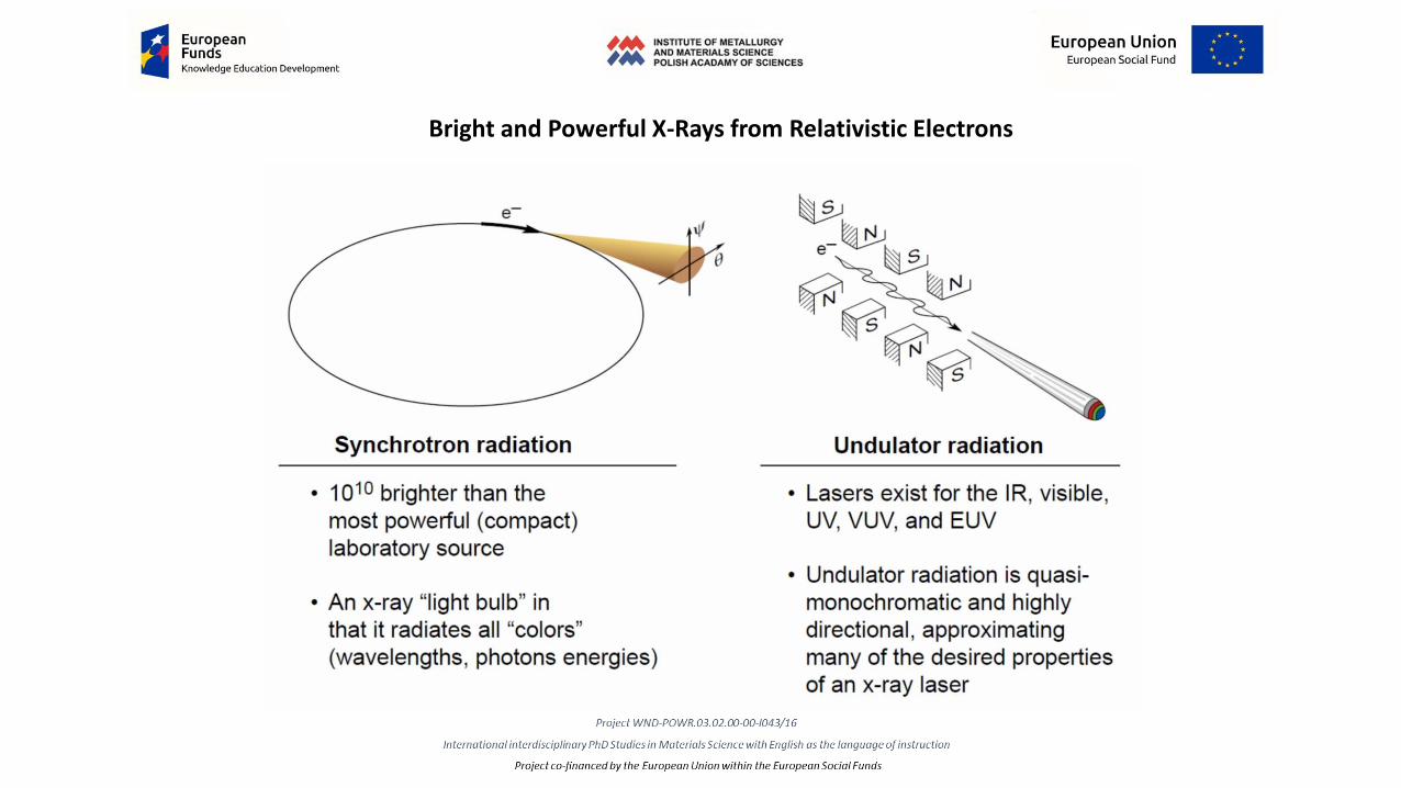
Bright and Powerful X-Rays from Relativistic Electrons

The acceleration of electrons takes place in a highfrequency chamber. Initially, the speed of electronsincreases, followed mainly by mass (relativisticeffects) increases. In order to constantly increasethe energy of electrons, the accelerating field mustbe synchronized with the time of the circuit byelectrons. When the required energy is reached,the electrons fall on the disc where the testnuclear reaction takes place. This cycle shallnormally be resumed at a frequency ofapproximately 50 Hz.
Storage ring


ELETTRA Synchrotron Centre (Trieste), SAXS BeamLine 5.2. Year 2000

A single storage ring serves many scientific user group


X-ray detectors
X-ray detectors are devices used to measure the flux, spatial distribution, spectrum and/or other properties of X-rays.
X-ray detectors vary in shape and function depending on their purpose. They can be divided into two major categories: imaging detectors and dose measurement.
• Imaging detectors such as those used for radiography were originally based on photographic plates and and later photographic X-ray films, but are now mostly replaced by various digital detector types such as image platesand flat panel detectors.
• For radiation protecttion direct exposure hazard is often evaluated using ionization chambers, while dosimeters are used to measure the radiation dose a person has been exposed to. X-ray spectra can be measured either by energy dispersive or wavelength dispersive spectrometers.
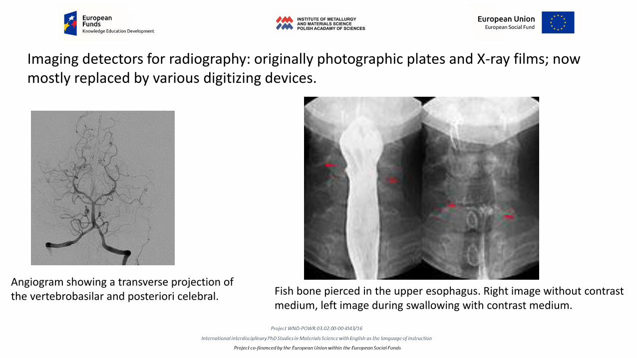
Imaging detectors for radiography: originally photographic plates and X-ray films; now mostly replaced by various digitizing devices.
Angiogram showing a transverse projection of the vertebrobasilar and posteriori celebral. Fish bone pierced in the upper esophagus. Right image without contrast
medium, left image during swallowing with contrast medium.

X-ray computed tomography (X-ray CT) or computerized axial tomography scan (CAT scan),
(makes use of computer-processed combinations ofmany X-ray images taken from different angles to producecross-sectional images (virtual 'slices') of specific areas of ascanned object, allowing the user to see inside the objectwithout cutting).
Typical screen layout for diagnostic software, showing one 3D and three MPR views.


Properties of X-rays(electromagnetic wave)
•absorption (attenuation in material medium)
•scattering (coherent and fluorescent)
•refraction (air - solid body; 1-n = 10-6)
• total reflection (q = 10’ 30’)
• magneto-”optical” Kerr effect

Absorption (attenuation in material medium)Attenuation (in some contexts also called extinction) is the gradual loss in intensity of any kind of flux through a medium
If X-rays of intensity I0 are incident on a sample, the extent of absorption depends on the photon energy E and sample thickness t. According to Beer’s Law, the transmitted intensity It is:
It (t) = I0e−μ(E)t
where μ(E) is the energy-dependent X-ray absorption coefficient.
Over large energy regions, μ(E) is a smooth function of the photon energy, varying approximately as μ(E) ∼ d Z4/m E3 . Here d denotes thetarget density while Z and m are the atomic number and mass, respectively. Thus, μ(E) decreases with increasing photon energy. If thelatter equals or exceeds the binding energy of a core electron, however, a new absorption channel is available in which the photon isannihilated thereby creating a photoelectron and a core-hole. This leads to a sharp increase in absorption coefficient. Above theabsorption edge, the difference between the photon energy and the binding energy is converted into kinetic energy of the photoelectronand μ(E) continues to decrease with increasing photon energy. After a short time of the order of 10−15 s, the core-hole is filled by an electronfrom a higher energy state. The corresponding energy difference is released mainly via fluorescence X-ray or Auger electron emission.
(a) Schematic of incident and transmitted X-ray beam, (b) absorption coefficient μ(E) versusphoton energy E around an absorption edge

Abso
rpti
on
Energy of radiation
K
L
EKa EKb
wavelengthKb Ka
K
L
Absorption edge

X-ray scattering techniques are a family of non-destructive analytical techniques which reveal information about the crystalstructure, chemical composition, and physical properties of materials and thin films. These techniques are based onobserving the scattered intensity of an x-ray beam hitting a sample as a function of incident and scattered angle,polarization, and wavelength or energy. (X-ray scattering is different from X-ray diffraction).
Elastic scatteringMaterials that do not have long range order may also be studied by scattering methods that rely on elastic scattering ofmonochromatic X-rays.
• Small-angle X-ray scattering (SAXS) is a technique where the elastic scattering of x-rays (wavelength 0.1 ... 0.2 nm) by asample which has inhomogeneities in the nm-range, is recorded at very low angles (typically 0.1 - 10°). This angularrange contains information about the shape and size of macromolecules, characteristic distances of partially orderedmaterials, pore sizes, and other data. SAXS is capable of delivering structural information of macromolecules between 5and 25 nm, of repeat distances in partially ordered systems of up to 150 nm. USAXS (ultra-small angle X-ray scattering)can resolve even larger dimensions.
• X-ray refflectivity is an analytical technique for determining thickness, roughness, and density of single layer andmultilayer thin films.
• Wide-angle X-ray scattering (WAXS), a technique concentrating on scattering angles 2θ larger than 5°.

Inelastic scatteringWhen the energy and angle of the inelastically scattered X-rays are monitored, scattering techniques can be used to probethe electronic band structure of materials. Inelastic scattering alters the phase of the diffracted x-rays, and as a result do notproduce useful data for x-ray diffraction. Rather, inelastically scattered x-rays contribute to the background noise in adiffraction pattern.
• Compton scattering is the inelastic scattering of a photon by a charged particle, usually an electron. It results in adecrease in energy of the photon (which may be an x-ray or gamma ray photon), called the Compton effect. Part of theenergy of the photon is transferred to the recoiling electron. Inverse Compton scattering exists, in which a chargedparticle transfers part of its energy to a photon.
A photon of wavelength λ comes in from the left, collides with atarget at rest, and a new photon of wavelength λ' emerges at anangle Θ.

• Resonant Inelastic X-ray Scattering (RIXS) is an X-ray spectroscopy technique used to investigate the
electronic structure of molecules and materials. It is a resonant technique because the energy of the incident
photon is chosen such that it coincides with, and hence resonates with, one of the atomic x-ray absorption
edges of the system. The resonance can greatly enhance the inelastic scattering cross section, sometimes by
many orders of magnitude. The RIXS event can be thought of as a two-step process. Starting from
the initial state, absorption of an incident photon leads to creation of an excited intermediate state, that has a
core hole. From this state, emission of a photon leads to the final state. In a simplified picture the absorption
process gives information of the empty electronic states, while the emission gives information about the
occupied states. In the RIXS experiment these two pieces of information come together in a convolved manner,
strongly perturbed by the core-hole potential in the intermediate state. RIXS studies can be performed using
both soft and hard x-ray.
Direct RIXS process. The incoming x-rays excite an electron from a deep-lying core levelinto the empty valence. The empty core state is subsequently filled by an electron fromthe occupied states under the emission of an x-ray. This RIXS process creates a valenceexcitation with momentum k′ − k and energy ħω − ħω′ .

X-ray Raman scattering (XRS) is non-resonant inelastic scattering of x-rays from core electrons, in which a high-energy x-ray photon gives energy to a core electron, exciting it to an unoccupied state. The process is in principle analogous to x-rayabsorption (XAS), but the energy transfer plays the role of the x-ray photon energy absorbed in x-ray absorption, exactly asin Raman scattering in optics vibrational low-energy excitations can be observed by studying the spectrum of lightscattered from a molecule. Because the energy (and therefore wavelength) of the probing x-ray can be chosen freely andis usually in the hard x-ray regime, certain constraints of soft x-rays in the studies of electronic structure of the materialare overcome. For example, soft x-ray studies may be surface sensitive and they require a vacuum environment. Thismakes studies of many substances, such as numerous liquids impossible using soft x-ray absorption. One of the mostnotable applications in which x-ray Raman scattering is superior to soft x-ray absorption is the study of soft x-rayabsorption edges in high pressure. Whereas high-energy x-rays may pass through a high-pressure apparatus likea diamond anvil cel and reach the sample inside the cell, soft x-rays would be absorbed by the cell itself.
Refraction
X-ray optics is the branch of optics that manipulates X-rays instead of visible light. While lenses for visible light are madeof transparent materials that can have a refractive index substantially larger than 1, for X-rays the index of refraction isslightly smaller than unity. The principal methods to manipulate X-rays are therefore by reflection, diffractionand interference. Examples of applications include X-ray microscopes and X-ray telescopes Refraction is the basis forthe compound refractive lens, many small X-ray lenses in series that compensate by their number for the X-rays' minuteindex of refraction. The imaginary part of the refractive index, corresponding to absorption, can also be used tomanipulate X-rays: one example is the pin-hole camera, which also works for visible light.

ReflectionThe basic idea is to reflect a beam of X-rays from a surface and to measure the intensity of X-rays reflected in the speculardirection (reflected angle equal to incident angle). It has been shown that a reflection off a parabolic mirror followed by areflection off a hyperbolic mirror can lead to the focusing of X-rays. Since the incoming X-rays must strike the tilted surfaceof the mirror, the collecting area is small. It can, however, be increased by nesting arrangements of mirrors inside eachother.
Several designs have been used in X-ray telescopes based on grazingincidence reflection: the Kirkpatrick-Baez design and a couple ofdesigns by Wolter.
A Wolter telescope is a telescope for X-rays using only grazing incidence optics. Visible light telescopes are built with either lenses or parabolic mirrors at nearlynormal incidence (that is, a nearly perpendicular angle of reflection). Neither works well for X-rays. Lenses for visible light are made of a transparent materialwith an index of refraction substantially different from one, but there is no equivalent material for x-rays. Conventional mirror telescopes work poorly in the X-rays as well, since the light hits the mirrors at near-normal incidence, where the X-rays are transmitted or absorbed, not reflected. X-rays mirrors can be built,but only if the angle from the plane of reflection is very low (typically 10 arc-minutes to 2 degrees). The most commonly used reflective materials for X-raymirrors are gold and iridium.

Thank you