Characterisationof asaddle eldfastatombeamsourceandits … · · 2011-04-01D. Sarangi!,*, O.S....
19
* Corresponding author. E-mail address: dsarangi@cnrs-imn.fr (D. Sarangi). Vacuum 58 (2000) 609 }627 Characterisation of a saddle "eld fast atom beam source and its application to the growth of diamond-like carbon "lms D. Sarangi!,*, O.S. Panwar", Sushil Kumar", R. Bhattacharyya" !Institut des Materiaux Jean-Rouxel-LPCM, 2 rue de la Houssiniere BP32229, Nantes 44322, France "National Physical Laboratory, Thin Film Technology Group, Dr. K.S. Krishnan Road, New Delhi 110 012, India Received 9 February 2000; accepted 5 May 2000 Abstract The use of saddle "eld fast atom beam (FAB) sources to grow diamond-like carbon (DLC) "lms is attractive due to its dc and rf attributes. This paper reports the detailed analysis of the beam coming out from the FAB source using argon (Ar), methane (CH 4 ) and acetylene (C 2 H 2 ) as source gases. Three operation modes of the FAB source are found, viz. glow discharge mode, transition mode and oscillation mode. A new process parameter, applied power, is de"ned for characterisation of the FAB source. Energy distribution analysis shows that the mean energy of the radicals coming out of the FAB source lies within 50% of the applied voltage to the FAB source. The neutralisation coe$cient of the beam was estimated to be more than 90% and was found to be almost independent of the discharge current of the FAB source. It will be seen through this characterisation study that a completely novel technique has been found to deposit DLC "lms, simultaneously by neutral and ionic radicals. The mechanical and opto-electronic properties of these DLC "lms are discussed. The role of ion assistance is seen in hardening the "lms. DLC "lms deposited by ionic radicals show better opto-electronic properties as measured by photothermal de#ection spectroscopy (PDS). ( 2000 Elsevier Science Ltd. All rights reserved. Keywords: Saddle "eld fast atom beam (FAB) source; Energy distribution; Neutralisation coe$cient; DLC; PDS 1. Introduction The development of saddle "eld fast atom beam (FAB) sources opened a new era of material processing of amorphous thin "lms in a very uncomplicated manner. Glow discharge (GD) 0042-207X/00/$ - see front matter ( 2000 Elsevier Science Ltd. All rights reserved. PII: S 0 0 4 2 - 2 0 7 X ( 0 0 ) 0 0 3 6 6 - 3
Transcript of Characterisationof asaddle eldfastatombeamsourceandits … · · 2011-04-01D. Sarangi!,*, O.S....

*Corresponding author.E-mail address: [email protected] (D. Sarangi).
Vacuum 58 (2000) 609}627
Characterisation of a saddle "eld fast atom beam source and itsapplication to the growth of diamond-like carbon "lms
D. Sarangi!,*, O.S. Panwar", Sushil Kumar", R. Bhattacharyya"
!Institut des Materiaux Jean-Rouxel-LPCM, 2 rue de la Houssiniere BP32229, Nantes 44322, France"National Physical Laboratory, Thin Film Technology Group, Dr. K.S. Krishnan Road, New Delhi 110 012, India
Received 9 February 2000; accepted 5 May 2000
Abstract
The use of saddle "eld fast atom beam (FAB) sources to grow diamond-like carbon (DLC) "lms isattractive due to its dc and rf attributes. This paper reports the detailed analysis of the beam coming out fromthe FAB source using argon (Ar), methane (CH
4) and acetylene (C
2H
2) as source gases. Three operation
modes of the FAB source are found, viz. glow discharge mode, transition mode and oscillation mode. A newprocess parameter, applied power, is de"ned for characterisation of the FAB source. Energy distributionanalysis shows that the mean energy of the radicals coming out of the FAB source lies within 50% of theapplied voltage to the FAB source. The neutralisation coe$cient of the beam was estimated to be more than90% and was found to be almost independent of the discharge current of the FAB source. It will be seenthrough this characterisation study that a completely novel technique has been found to deposit DLC "lms,simultaneously by neutral and ionic radicals. The mechanical and opto-electronic properties of these DLC"lms are discussed. The role of ion assistance is seen in hardening the "lms. DLC "lms deposited by ionicradicals show better opto-electronic properties as measured by photothermal de#ection spectroscopy(PDS). ( 2000 Elsevier Science Ltd. All rights reserved.
Keywords: Saddle "eld fast atom beam (FAB) source; Energy distribution; Neutralisation coe$cient; DLC; PDS
1. Introduction
The development of saddle "eld fast atom beam (FAB) sources opened a new era of materialprocessing of amorphous thin "lms in a very uncomplicated manner. Glow discharge (GD)
0042-207X/00/$ - see front matter ( 2000 Elsevier Science Ltd. All rights reserved.PII: S 0 0 4 2 - 2 0 7 X ( 0 0 ) 0 0 3 6 6 - 3

Fig. 1. Potential pro"le of saddle "eld FAB discharge together with that of dc and rf PECVD discharges (reproducedfrom Ref. [1]).
decomposition by either dc or rf (radio frequency) excitation, of the hydrocarbon gases, is themore conventional technique. Both these methods of plasma excitation have certain drawbacksand one would prefer to have advantages speci"c to both these techniques and none of theirinherent disadvantages. It may, at "rst sight, appear to be a rather strange idea. However, saddle"eld source deposition does indeed come very close to this ideal. The combined attributes of dc andrf discharges make it a novel technique for thin-"lm growth applications. The potential pro"le [1]of the saddle "eld FAB discharge together with that of dc and rf plasma enhanced chemical vapourdeposition (PECVD) discharges are shown in Fig. 1. From this "gure it is clear that the potentialdistribution in a FAB source is similar to that in the rf PECVD (GD) technique though dc voltagesare used to operate such FAB sources. Earlier FAB sources were used for cleaning, milling, etching,thinning (the specimen preparation for TEM) and sputtering applications and also for a variety ofsurface analytical techniques. Franks [2] "rst used the source to deposit diamond-like carbon(DLC) "lms. His attempts to deposit DLC "lms using methane (CH
4) as the source gas lead to the
etching of the substrates. But we are able to tailor the process parameters to grow DLC "lms usingCH
4as feed gas by the FAB technique [3]. The advantages of using a FAB source to grow DLC
"lms, as compared to conventional rf self-bias technique, are: (i) no rf matching problem;(ii) uncomplicated power supply; (iii) ease of scale up (modular design) and (iv) simpli"ed geometrysystem.
610 D. Sarangi et al. / Vacuum 58 (2000) 609}627

It is to be emphasised that the beam coming out of the FAB source is not fully neutral; a fractionof ionised species is also present along with the neutrals. Franks [4] in his experiment estimated the#ux of the beam coming out of the FAB source to be of the order of 10}40 mA, under the sourceoperation voltage of 0.8}3 kV. He also concluded, after etching rate studies due to ion and neutrals,that neutral beams have energies and #ux densities similar to the ion beams. Atom Tech. Ltd.(Formerly Ion Tech. Ltd.) were the "rst to commercialise the atom beam sources. They nowmarket di!erent types of FAB sources, like B93, B95, FAB 110 series, etc., with a range ofcapabilities.
Saied et al. [5] carried out a full characterisation study of the FAB source and the beam comingout of the FAB source used (FAB 11). The operation modes of a FAB source have been found to besimilar to a saddle "eld ion source [6], namely a glow discharge mode (&10~4 mbar), transitionmode (lower than 10~4 mbar pressure) and oscillation mode (&10~5 mbar pressure). Anode currentor discharge current increases linearly with the discharge voltage or anode voltage. Also theyfound an increase in the beam current density with decrease in pressure at a given value ofdischarge current. They found that the source operated more e$ciently in the range 10~5} 7]10~5 mbar. When operated in its most e$cient mode, at low chamber pressure, the beamemitted from the source contained about 50% of the fast atoms. The source can be used toproduce a beam composed almost entirely of fast atoms at higher chamber pressure, but this isof little consequence since, under these conditions, the atom beam #ux is too low for mostapplications. The particle beam has a very broad energy distribution, typically producing1100 eV full-width at half-maximum (FWHM) at 4 keV. They found the energy of the fastatoms measured from the spectra was the same as when a signi"cant proportion of the beamconsisted of ions. Shimokawa et al. [7}10] made a series of characterisation studies of thebeam coming out of a hollow cathode type FAB source. Using a magnetic "eld, perpendicularto the motion of electron, they were able to produce high-power FAB sources. These types ofFAB sources have large operating range (1]10~5 } 1]10~3 mbar). The beam coming outfrom this source has neutralisation coe$cient &95% and beam current density of&0.1}1.0 mA/cm2. Voevodin et al. [11] found that the #ux coming out from the FAB source (B93)contains a signi"cant percentage of ions. The ion composition of #uxes greatly depends on thedistance from the source. In the near-source region a level of ionisation of 80% was observedby them.
In this paper a detailed characterisation of the beam coming out of the FAB source has beencarried out. It will be seen through this characterisation study that a completely novel techniquehas been found to deposit DLC "lms, simultaneously by neutral and ionic radicals.
2. Experimental procedure
The working model [4] of a FAB source is shown in Fig. 2. It consist of two anodes in the form ofwires or rods surrounded by a cathode. When a dc positive voltage is applied to the source:
1. Electrons are induced to oscillate between cathodes under the action of a dc "eld.2. Electrons originating from a sector of the cathode travel through the anode region towards the
opposite cathode sector, are retarded, return and continue to oscillate about a central saddle pointin the potential "eld.
D. Sarangi et al. / Vacuum 58 (2000) 609}627 611
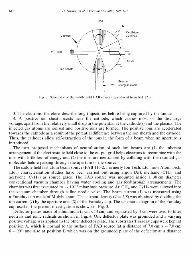
Fig. 2. Schematic of the saddle "eld FAB source (reproduced from Ref. [2]).
3. The electrons, therefore, describe long trajectories before being captured by the anode.4. A positive ion sheath exists near the cathode, which carries most of the discharge
voltage, apart from the relatively small drop in the potential at the cathode(s) and the plasma. Theinjected gas atoms are ionised and positive ions are formed. The positive ions are acceleratedtowards the cathode as a result of the potential di!erence between the ion sheath and the cathode.Thus, the cathodes allow self-extraction of the ions in the form of a beam when an aperture isintroduced.
The two proposed mechanisms of neutralisation of such ion beams are (1) the inherentarrangement of the electrostatic "eld close to the output grid helps electrons to recombine with theions with little loss of energy and (2) the ions are neutralised by colliding with the residual gasmolecules before passing through the aperture of the source.
The saddle "eld fast atom beam source (FAB 110-2, Formerly Ion Tech. Ltd., now Atom Tech.Ltd.,) characterisation studies have been carried out using argon (Ar), methane (CH
4) and
acetylene (C2H
2) as source gases. The FAB source was mounted inside a 30 cm diameter
conventional vacuum chamber having water cooling and gas feedthrough arrangements. Thechamber was "rst evacuated to &10~5 mbar base pressure. Ar, CH
4and C
2H
2were allowed into
the vacuum chamber through a "ne needle valve. The beam current (I) was measured usinga Faraday cup made of Molybdenum. The current density (J"I/S) was obtained by dividing theion current (I) by the aperture area (S) of the Faraday cup. The schematic diagram of the Faradaycup used in the present investigation is shown in Fig. 3.
De#ector plates made of alluminium (5 cm]14 cm) and separated by 4 cm were used to "lterneutrals and ionic radicals as shown in Fig. 4. One de#ector plate was grounded and a varyingpositive voltage was applied to the other de#ector plate. The substrates/Faraday cups were kept atposition A, which is normal to the surface of FAB source (at a distance of 7.0 cm, r"7.0 cm,h"903) and also at position B which was on the grounded plate of the de#ector at a distance
612 D. Sarangi et al. / Vacuum 58 (2000) 609}627
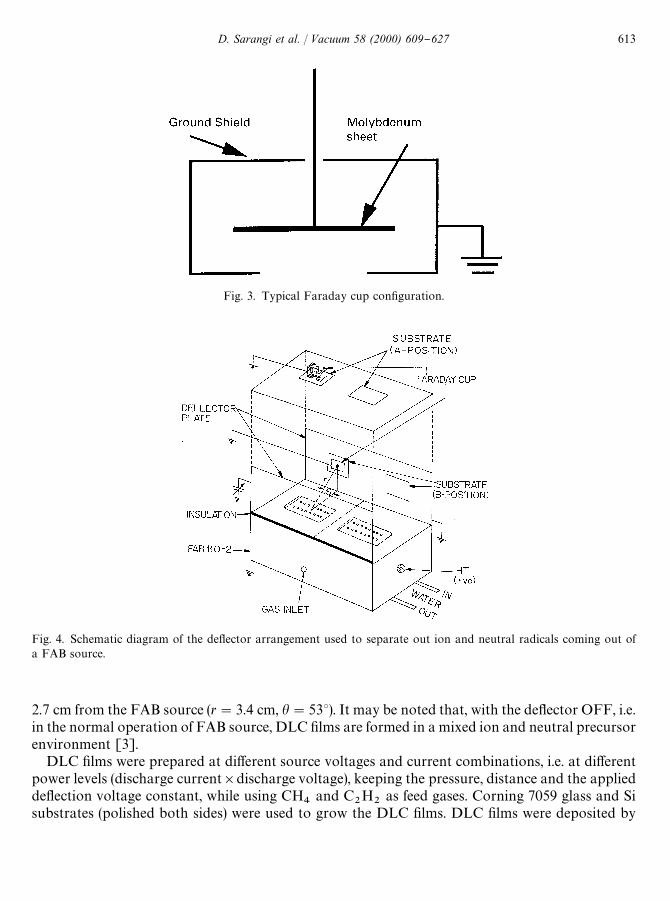
Fig. 4. Schematic diagram of the de#ector arrangement used to separate out ion and neutral radicals coming out ofa FAB source.
Fig. 3. Typical Faraday cup con"guration.
2.7 cm from the FAB source (r"3.4 cm, h"533). It may be noted that, with the de#ector OFF, i.e.in the normal operation of FAB source, DLC "lms are formed in a mixed ion and neutral precursorenvironment [3].
DLC "lms were prepared at di!erent source voltages and current combinations, i.e. at di!erentpower levels (discharge current]discharge voltage), keeping the pressure, distance and the appliedde#ection voltage constant, while using CH
4and C
2H
2as feed gases. Corning 7059 glass and Si
substrates (polished both sides) were used to grow the DLC "lms. DLC "lms were deposited by
D. Sarangi et al. / Vacuum 58 (2000) 609}627 613

Fig. 5. Variation of (a) discharge voltage vs. chamber pressure and (b) beam currents density vs. chamber pressure ata series of constant discharge currents using Ar as source gas.
applying 1.6}2.0 kV voltage to the de#ector plate (no glow discharge near the positive biased platewas observed at this voltage and pressure). This enabled the ionic radicals to be de#ected towardsthe grounded de#ector plate, while the path of the neutral radicals remained unchanged.
3. Results and discussion
3.1. Fab source characterisation
3.1.1. Operating regionsThe operational modes of the saddle "eld fast atom beam (FAB) source (FAB 110-2) studied in
this present investigation are found to be similar to those reported by Saied et al. [5] namely, a glowdischarge mode, transition mode and oscillation mode.
The modes of operation of the FAB source have been studied as a function of pressure and areillustrated in Fig. 5. Fig. 5(a) shows the variation of the discharge voltage with chamber pressure,for the three di!erent discharge current settings when Ar is used as the source gas. Fig. 5(b) showsthe variation of the beam current density with the chamber pressure for di!erent discharge currentsettings for the same source gas.
614 D. Sarangi et al. / Vacuum 58 (2000) 609}627

The glow discharge mode was observed in the present experiments under low-voltage (&0.5 kV)and high-pressure (&10~1 mbar) condition, which is found to be higher than the pressure rangereported by Saied et al. [5] for their experiments with a FAB-11 source. Electron oscillations in thesaddle "eld region, which is responsible for the e$cient operation of the source, has been found tobe reduced in this pressure range. This has predictably resulted in lower ionisation inside thesource, and thus a lower beam current. The transition mode occurs at a slightly lower pressure(3!2]10~2 mbar), just below the glow discharge region. In this case, the mean free path of theoscillating electrons increases, leading to a higher ionisation e$ciency. This, in turn, results in anincrease of the beam current density. The oscillation mode has been found to occur in the pressurerange below 10~2 mbar. In this case, the oscillating mean free path and as well as the ionisatione$ciency are high, leading again to an increase in the beam current density. Similar modes ofoperation were also observed when CH
4and C
2H
2were used as the source gases. Thus, selection
of a suitable operating mode, on the basis of the desired application, is found to be a very importantconsideration.
3.1.2. Discharge current vs. discharge voltageThe variation of the discharge voltage (anode voltage, A
7) with the discharge current (anode
current, A#) of the FAB source used is shown in Fig. 6. Fig. 6(a) shows the variation of A
7with
A#
when Ar gas was used as the source gas at 25]10~3 mbar pressure and at di!erent #owrate conditions. It is evident from this "gure that the value of A
7increased linearly with the
value of A#
for all #ow rate conditions and the value of A7
decreased with the increase of gas-#owrate for a particular value of A
#. It is very important to mention at this stage that the power
supply used to operate FAB source is a current-controlled device. It, therefore, becomes possible,by keeping all other parameters constant, for the discharge voltage to be increased suitably byincreasing the discharge current only. Therefore, the decrease of discharge voltage, at aparticular discharge current, with the increase of gas-#ow rate is due to higher ionisation of thefeed gas inside the FAB source. This can be seen to have e!ectively reduced the plasmaresistance.
Figs. 6(b) and (c) show the variation of A7with A
#for CH
4and C
2H
2as source gases and having
a similar set of operation conditions used in the case of Ar discharge. The variation of A7with A
#is
also found to be almost linear in this case as well. However, in both these cases (CH4
and C2H
2),
dependence of discharge voltage on discharge current appears to have two distinct patterns, one for#ow rates below 1 sccm and other above that. In case of Ar discharge, the variations are distinct inall di!erent #ow rates. But in the above two cases of the hydrocarbon discharge, the dischargevoltage attains almost similar values for the #ow rates of 2, 6 and 10 sccm. It seems that for gas-#owrates above 2 sccm the ionisation of the gas inside the FAB source begins to saturate. It is,therefore, concluded that the FAB discharges using Ar as a source gas and hydrocarbon gases assource gases are, indeed, di!erent.
Fig. 7(a) shows the variation of the discharge voltage with discharge current at gas-#ow rateless than 1 sccm and at two di!erent pressures, 25]10~3 and 5]10~3 mbar, using Ar, CH
4and
C2H
2as source gases. The value of A
7is strongly dependent on pressure and has been found
to increase with the decrease of pressure. In this "gure, a clear distinction of the variation of A7
with A#has been observed for the other source gases used. But as shown in Fig. 7(b}d) any speci"c
trend in this variation is not discernible. This indicates that, at higher #ow rates, the variation
D. Sarangi et al. / Vacuum 58 (2000) 609}627 615

Fig. 6. Variation of discharge voltage vs. discharge current when (a) Ar was used as source gas, (b) CH4
was used assource gas and (c) C
2H
2was used as source gas at 25]10~3 mbar chamber pressure and at di!erent gas #ow rate
conditions.
is strongly dependent on the source gas used and it follows di!erent trends for di!erent sets ofconditions.
From the above observations, it is clear that discharge voltage not only depends on dischargecurrent, it also depends on pressure, #ow rate (weakly) and type of source gas used. Therefore, theterm, applied power, which is equal to the product of discharge current and the correspondingdischarge voltage, could be better used as a reference parameter to describe the properties of the"lms so made.
The variation of power developed with the discharge current is shown in Fig. 8 in case of Ar,CH
4and C
2H
2as source gases at 25]10~3 mbar pressure and at di!erent #ow rates. From this
"gure it is clear that the developed power is limited by the #ow rate. So, when Ar is used as source
616 D. Sarangi et al. / Vacuum 58 (2000) 609}627

Fig. 7. Variation of discharge voltage vs. discharge current at gas #ow rate (a) (1 sccm, (b) 2 sccm, (c) 6 sccm and (d)10 sccm using Ar, CH
4and C
2H
2as source gases at two di!erent chamber pressures.
D. Sarangi et al. / Vacuum 58 (2000) 609}627 617

Fig. 8. Variation of power developed vs. discharge current when (a) Ar was used as source gas, (b) CH4
was used assource gas and (c) C
2H
2was used as source gas at 25]10~3 mbar chamber pressure and at di!erent gas #ow rate
conditions.
gas, a decrease in #ow leads to a higher developed power (Fig. 8(a)). But this is not true in the casewhere hydrocarbons are used as source gases as shown in Figs. 8(b) and (c) for CH
4and C
2H
2.
Here the power developed is found to be weakly dependent upon the #ow rate at particularpressure and is almost identical under all #ow conditions.
3.2. Current density measurement
3.2.1. Normal operationThe variation of current density (J) with the applied power for Ar as source gas is shown
in Fig. 9(a) for di!erent set of #ow conditions and at a pressure 25]10~3 mbar. The valueof J depends on the applied power and is found to increase linearly with the power. The value
618 D. Sarangi et al. / Vacuum 58 (2000) 609}627

Fig. 9. Variation of beam current density vs. applied power when (a) Ar was used as source gas, (b) CH4
was used assource gas and (c) C
2H
2was used as source gas at 25]10~3 mbar chamber pressure and at di!erent gas #ow rate
conditions.
of J was also found to increase with the decrease in #ow of Ar, at particular power and Arpressure used.
Figs. 9(b) and (c) show the variation of J with the applied power when CH4
and C2H
2are used
as the source gases, at 25]10~3 mbar pressure and di!erent #ow rates of the hydrocarbon gasesused. The value of J was also found to increase with the applied power. It is abundantly clear fromthese "gures that, at a particular gas pressure condition, current density does not appear to dependso much on the #ow rate of the hydrocarbon gas used. Therefore, while dealing with thehydrocarbon gases at a particular pressure, #ow rate does not constitute a critical processparameter.
D. Sarangi et al. / Vacuum 58 (2000) 609}627 619
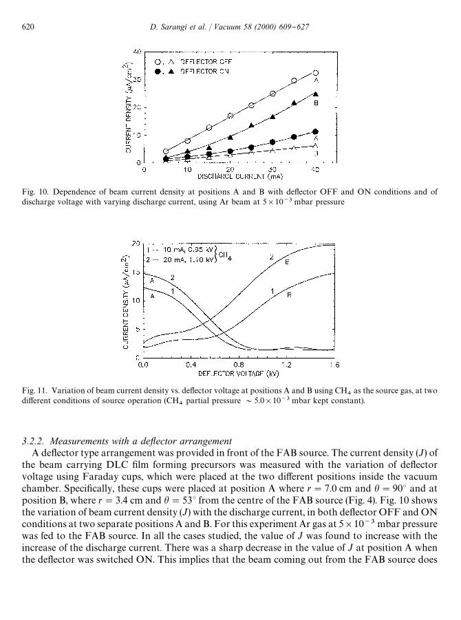
Fig. 11. Variation of beam current density vs. de#ector voltage at positions A and B using CH4
as the source gas, at twodi!erent conditions of source operation (CH
4partial pressure &5.0]10~3 mbar kept constant).
Fig. 10. Dependence of beam current density at positions A and B with de#ector OFF and ON conditions and ofdischarge voltage with varying discharge current, using Ar beam at 5]10~3 mbar pressure
3.2.2. Measurements with a deyector arrangementA de#ector type arrangement was provided in front of the FAB source. The current density (J) of
the beam carrying DLC "lm forming precursors was measured with the variation of de#ectorvoltage using Faraday cups, which were placed at the two di!erent positions inside the vacuumchamber. Speci"cally, these cups were placed at position A where r"7.0 cm and h"903 and atposition B, where r"3.4 cm and h"533 from the centre of the FAB source (Fig. 4). Fig. 10 showsthe variation of beam current density (J) with the discharge current, in both de#ector OFF and ONconditions at two separate positions A and B. For this experiment Ar gas at 5]10~3 mbar pressurewas fed to the FAB source. In all the cases studied, the value of J was found to increase with theincrease of the discharge current. There was a sharp decrease in the value of J at position A whenthe de#ector was switched ON. This implies that the beam coming out from the FAB source does
620 D. Sarangi et al. / Vacuum 58 (2000) 609}627

Fig. 12. Variation of beam current density vs. de#ector voltage at positions A and B, using CH4
and C2H
2as the source
gases, at same conditions of source operation.
not consist of neutrals alone, i.e., a fraction of ionised radicals are responsible for the formation ofthe beam. The high positive de#ector voltage (1.6 } 2.0 kV) de#ects the positive ions away from A.Similarly, the value of J at position B increased sharply when the de#ector was switched ON. Inthis case, the de#ected ionic radicals contributed to the current. The position B was chosen afterrepeated search and it was found that, only at that particular position, the mean current densityshowed a maximum.
The variation of J vs. the de#ector voltage at both A and B positions, using CH4
as feed gas, atdi!erent applied powers to FAB source, is shown in Fig. 11. It was found that the value of J, in boththe positions (A and B), increases with the increase of power applied to the FAB source, when thede#ector is in the OFF condition. This current density is, however, small at position B andis believed to be primarily due to a combination of ion and neutral precursors that may possiblybe reaching position B at this pressure. At position A, the value of J is found to decrease withthe de#ector voltage, whereas, at position B, J increases with the de#ector voltage. The valueof J above 1.0 kV de#ector voltage at position A is found to be small and this does not seem tochange with the increase of de#ector voltage, whereas the value of J above 1.0 kV at positionB increases with the increase of de#ector voltage. This indicates that at position A, above 1.0 kVde#ector voltage, only neutral radicals are present, whereas, at position B only, ionic radicalsare present.
Fig. 12 shows the variation of J with the de#ector voltage at both A and B positions, usingCH
4and C
2H
2gases, keeping almost similar conditions of discharge (10 mA, 0.95 kV and
4}5]10~3 mbar pressure). It was found that the value of J at position A increases at de#ectorOFF position when one switches from CH
4to C
2H
2gas. Similar behaviour was also observed
at position B, but the value of J was found to be small during de#ector OFF condition. Further,for both the gases the value of J was found to decrease with the de#ector voltage. Also it wasfound to remain almost constant near the voltage (1.0 kV) applied to the FAB source. At highenough de#ector voltage the current recorded at A is most likely to be due to the secondaryelectrons emitted from the Mo sheet due to the bombardment of energetic neutrals. The value
D. Sarangi et al. / Vacuum 58 (2000) 609}627 621

Fig. 13. Energy distribution spectra of residual ions of CH4
gas at two di!erent discharge voltages. Inset shows theenergy distribution spectra of the Shimokawa et al. [7] work.
of J at position B was found to increase with the de#ector voltage for both the gases but whenC
2H
2gas was used, the current density increased more than when CH
4gas was admitted to the
FAB source.
3.3. Energy distribution of residual ions
The energy distribution spectra of residual ions was obtained by (1) measuring the currentdensity (J) with the increase of de#ector voltage (<) at position A (Fig. 12) and (2) di!erentiation(!dJ/d<) of the spectra [7]. The kinetic energy cited is the direct conversion of de#ector voltage.It is speculated that the energy distribution of neutrals in the present case may also show a similarpattern to that obtained for ions, as found by Shimokawa et al. [7] for their FAB source.
To "nd out the di!erence between the energy distribution at di!erent discharge voltages, twodi!erent conditions (10 mA, 0.95 kV and 20 mA, 1.10 kV at 4]10~3 mbar pressure) were chosenfor DLC "lms grown with CH
4gas admitted to the FAB source, as shown in Fig. 13. The energy
spectra in both the cases are fairly broad and with a half-width of 400 eV. In both the cases, themain peaks in the energy distribution appear at 50% of the discharge voltage and the resultobtained is found to agree with Shimokawa et al. [7]. They reported (as shown in the inset given atFig. 13) that the energy distribution of the ions at a pressure 8]10~4 mbar is broader and appearsat 25% of the discharge voltage with half-width 600 eV, whereas at pressure 2.7]10~5 mbar thepeak coincides with the FAB discharge voltage. The energy distribution spectra obtained for C
2H
2gas is also found to be similar in nature to that of CH
4gas but the relative intensity was higher.
Due to the limitation of pumping speed of the pump used in the present experiment, it was notpossible to operate the FAB source at elevated vacuum conditions, similar to that used byShimokawa et al. [7]. The important observation is that the beams coming out from the FABsource contain ions and neutrals of varying energies and the majority are at an energy which isapproximately half of the discharge voltage.
622 D. Sarangi et al. / Vacuum 58 (2000) 609}627

Fig. 14. Variation of the beam current vs. de#ector voltage. (The values I and I0
have been used to estimate beamneutralisation coe$cient.)
3.4. Beam neutralisation coezcient
The beam neutralisation coe$cient of the FAB source was estimated by measuring the current inboth the conditions, i.e. de#ector ON (de#ector voltage"1.6 kV) and de#ector OFF (de#ectorvoltage"0 V) and assuming the following relation to be valid [10]
g"I0(1#c
i)/[I
0(1#c
i)#c
0(I!I
0)],
where g is the neutralisation coe$cient, I and I0
are current recorded at position A when de#ectorvoltage is 0 V (OFF) and 1.6 kV (ON), respectively (Fig. 14), c
iis the yield of the secondary
electrons from the surface of the Mo target under the ion bombardment condition and c0
is theyield of the secondary electrons under energetic neutral particle bombardment. Ar was used for theestimation of beam neutralisation coe$cient experiments. The energies of the ions and the neutralscoming out from the FAB source were assumed to be the same. The neutralisation coe$cient of thebeam was estimated to be more than 90% and was found to be almost independent of the dischargecurrent of the FAB source, as shown in Fig. 15.
3.5. Filtered saddle xeld FAB deposited DLC xlms
During analysis of the beam coming out of the FAB source using the de#ector arrangement, itwas found that ionic and neutral precursors could be "ltered out and made to land at two di!erentlocations. This leads to a novel idea to deposit DLC "lms simultaneously by ionic and neutralradicals. The DLC "lms so formed were subsequently characterised [12,13]. The thickness of theDLC "lms grown were found to be in the range of &1000 As produced by positive radicals and&3000 As for neutrals, as measured by the Talystep thickness pro"ler (Rank, Taylor and Hobson).The main results of these characterisation studies are summarised below.
D. Sarangi et al. / Vacuum 58 (2000) 609}627 623
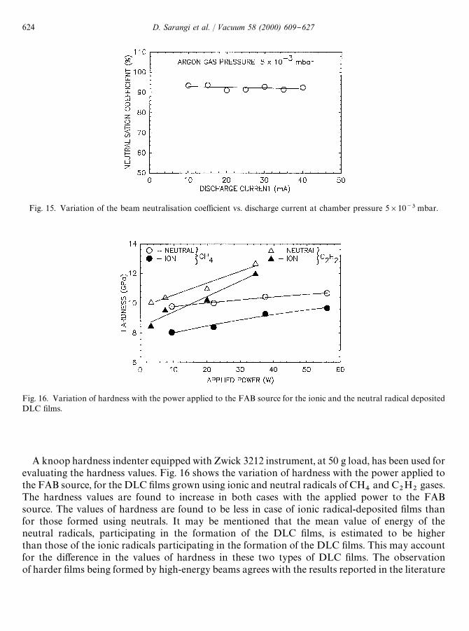
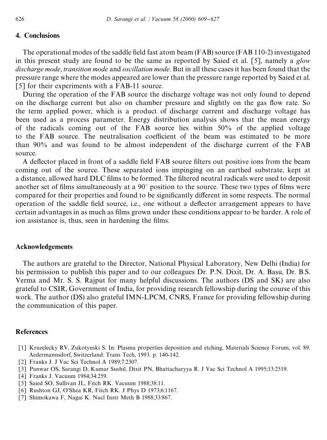
Fig. 16. Variation of hardness with the power applied to the FAB source for the ionic and the neutral radical depositedDLC "lms.
Fig. 15. Variation of the beam neutralisation coe$cient vs. discharge current at chamber pressure 5]10~3 mbar.
A knoop hardness indenter equipped with Zwick 3212 instrument, at 50 g load, has been used forevaluating the hardness values. Fig. 16 shows the variation of hardness with the power applied tothe FAB source, for the DLC "lms grown using ionic and neutral radicals of CH
4and C
2H
2gases.
The hardness values are found to increase in both cases with the applied power to the FABsource. The values of hardness are found to be less in case of ionic radical-deposited "lms thanfor those formed using neutrals. It may be mentioned that the mean value of energy of theneutral radicals, participating in the formation of the DLC "lms, is estimated to be higherthan those of the ionic radicals participating in the formation of the DLC "lms. This may accountfor the di!erence in the values of hardness in these two types of DLC "lms. The observationof harder "lms being formed by high-energy beams agrees with the results reported in the literature
624 D. Sarangi et al. / Vacuum 58 (2000) 609}627

Fig. 17. The dependence of Urbach energy (E0) with the applied power to the FAB source the of DLC "lms grown using
neutral and ionic radicals.
for the DLC "lms grown using ion beams [13]. It was observed that the values of the hardnessof these DLC "lms are lower than the DLC "lms prepared in a mixed environment (normalmode of operation). This, perhaps, goes to show that a mixed ion and neutral beam that is obtainedduring the normal operation of the source may, in fact, help the growing "lms to become harder,i.e. the hardness process is ion assisted. Further, DLC "lms deposited by ionic radicalson a grounded plate, placed very near to the aperture were not that hard and found tobe scratchable.
Transverse photothermal de#ection spectroscopy (PDS) was used to study the characteristicenergy of the Urbach edge or Urbach energy (E
0) of these DLC "lms. Fig. 17 shows the variation of
E0
with the applied power to the FAB source for neutral and ionic radical-deposited "lms usingboth CH
4and C
2H
2gases as the feed stock. The values of E
0are found to be less in ionic
radical-deposited "lms than neutral-deposited "lms, for both these gases used. One can possiblyinfer from these observations that ionic-radical-deposited DLC "lms are superior to neutralradical-deposited "lms, in as much as their characteristic energy of band tails are concerned. It isfound that the values of E
0for the DLC "lms deposited from the mixed ion and neutral
environment (normal operation of FAB source) are higher that the E0
values for the "lms depositedby the "ltered fast atom beam technique used in this experiment. This gives a clear picture that,though a mixed environment appears to be good for obtaining enhanced mechanical properties, forthe enhancement of opto-electronic properties one should, perhaps, create those conditions thatensure abundance of ionic radicals. This is because "lms showing smaller values of E
0have better
opto-electronic properties [14]. The values of Urbach energy (E0) evaluated for these mixed
ion-neutral beam deposited DLC "lms are found to be in the range of 260 } 280 meV. These valuesof E
0are obviously signi"cantly lower than the values of E
0(&500 meV) for DLC "lms grown
using rf glow discharge decomposition of CH4
gas [14] but much higher than the values of E0
(&50 meV) for the device quality hydrogenated amorphous silicon (a-Si : H) "lms reported in theliterature [14].
D. Sarangi et al. / Vacuum 58 (2000) 609}627 625
4. Conclusions
The operational modes of the saddle "eld fast atom beam (FAB) source (FAB 110-2) investigatedin this present study are found to be the same as reported by Saied et al. [5], namely a glowdischarge mode, transition mode and oscillation mode. But in all these cases it has been found that thepressure range where the modes appeared are lower than the pressure range reported by Saied et al.[5] for their experiments with a FAB-11 source.
During the operation of the FAB source the discharge voltage was not only found to dependon the discharge current but also on chamber pressure and slightly on the gas #ow rate. Sothe term applied power, which is a product of discharge current and discharge voltage hasbeen used as a process parameter. Energy distribution analysis shows that the mean energyof the radicals coming out of the FAB source lies within 50% of the applied voltageto the FAB source. The neutralisation coe$cient of the beam was estimated to be morethan 90% and was found to be almost independent of the discharge current of the FABsource.
A de#ector placed in front of a saddle "eld FAB source "lters out positive ions from the beamcoming out of the source. These separated ions impinging on an earthed substrate, kept ata distance, allowed hard DLC "lms to be formed. The "ltered neutral radicals were used to depositanother set of "lms simultaneously at a 903 position to the source. These two types of "lms werecompared for their properties and found to be signi"cantly di!erent in some respects. The normaloperation of the saddle "eld source, i.e., one without a de#ector arrangement appears to havecertain advantages in as much as "lms grown under these conditions appear to be harder. A role ofion assistance is, thus, seen in hardening the "lms.
Acknowledgements
The authors are grateful to the Director, National Physical Laboratory, New Delhi (India) forhis permission to publish this paper and to our colleagues Dr. P.N. Dixit, Dr. A. Basu, Dr. B.S.Verma and Mr. S. S. Rajput for many helpful discussions. The authors (DS and SK) are alsograteful to CSIR, Government of India, for providing research fellowship during the course of thiswork. The author (DS) also grateful IMN-LPCM, CNRS, France for providing fellowship duringthe communication of this paper.
References
[1] Kruzelecky RV, Zukotynski S. In: Plasma properties deposition and etching, Materials Science Forum, vol. 89.Aedermannsdorf, Switzerland: Trans Tech, 1993. p. 140-142.
[2] Franks J. J Vac Sci Technol A 1989;7:2307.[3] Panwar OS, Sarangi D, Kumar Sushil, Dixit PN, Bhattacharyya R. J Vac Sci Technol A 1995;13:2519.[4] Franks J. Vacuum 1984;34:259.[5] Saied SO, Sullivan JL, Fitch RK. Vacuum 1988;38:11.[6] Rushton GJ, O'Shea KR, Fitch RK. J Phys D 1973;6:1167.[7] Shimokawa F, Nagai K. Nucl Instr Meth B 1988;33:867.
626 D. Sarangi et al. / Vacuum 58 (2000) 609}627

[8] Shimokawa F, Kuwano H. J Appl Phys 1992;72:13.[9] Shimakawa F. J Vac Sci Technol A 1992;10:1352.
[10] Shimokawa F, Kuwono H. J Vac Sci Technol A 1994;12:2739.[11] Voevodin AA, Schneider JM, Caperaa C, Stevenson P, Matthews R. Vacuum 1995;46:299.[12] Sarangi D, Panwar OS, Kumar Sushil, Dixit PN, Bhattacharyya R. Surf Coat Technol 1997;94-95:356.[13] Sarangi D, Panwar OS, Kumar Sushil, Dixit PN, Bhattacharyya R. J Vac Sci Technol A 1998;16:203.[14] Mori T, Namba Y. J Vac Sci Technol A 1983;1:23.
D. Sarangi et al. / Vacuum 58 (2000) 609}627 627