Chapter4 Combinational Logic -...
23
Combinational Logic MEC520 디지털 공학 Jee-Hwan Ryu School of Mechanical Engineering Korea University of Technology and Education Korea University of Technology and Education Outputs are determined from the present inputs Consist of input/output variables and logic gates Sequential Circuits Outputs are determined from the present inputs and the state of the storage elements The state of the storage elements is a function of previous inputs Depends on present and past inputs Combinational circuits Binary signal from registers Binary signal to registers
Transcript of Chapter4 Combinational Logic -...

Combinational Logic
MEC520 디지털 공학
Jee-Hwan Ryu
School of Mechanical Engineering
Korea University of Technology and Education
Korea University of Technology and Education
Outputs are determined from the present inputsConsist of input/output variables and logic gates
Sequential CircuitsOutputs are determined from the present inputs and the state of the storage elementsThe state of the storage elements is a function of previous inputsDepends on present and past inputs
Combinational circuits
Binary signalfrom registers
Binary signalto registers

Korea University of Technology and Education
Analysis procedure
To determine the function from a given circuit diagram
Analysis procedureMake sure the circuit is combinational or sequential
No Feedback and memory elements
Obtain the output Boolean functions or the truth table
Korea University of Technology and Education
Boolean function from a logic diagramLabel all gate outputs with arbitrary symbols
Make output functions at each level
Substitute final outputs to input variables
Obtain Procedure-Boolean Function

Korea University of Technology and Education
Truth table from a logic diagramPut the input variables to binary numbers
Determine the output value at each gate
Obtain truth table
Obtain Procedure-Truth Table
Korea University of Technology and Education
Example

Korea University of Technology and Education
Procedure to design a combinational circuit1. Determine the required number of input and output from
specification
2. Assign a symbol to each input/output
3. Derive the truth table from the required relationship
4. Obtain the simplified Boolean functions
5. Draw the logic diagram and verify design correctness
Design Procedure
Korea University of Technology and Education
BCD to excess-3 code converterExcess-3 code : decimal digit+3
Design procedure1)Determine inputs/outputs
Inputs : A,B,C,D (0000∼1001)
Outputs : W,X,Y,Z (0011∼1100)
Code conversion example

Korea University of Technology and Education
Code conversion example
2) Derive truth table
Korea University of Technology and Education
3) Obtain simplified Boolean functions
Code conversion example

Korea University of Technology and Education
Code conversion example
4) Draw the logic diagram
Korea University of Technology and Education
Design a combinational circuit with three inputs and one output. The output is 1 when the binary value of the inputs is less than 3. The output is 0 otherwise.
Example

Korea University of Technology and Education
Binary adderHalf adder : performs the addition of 2-bits (x+y)
Full adder : performs the addition of 3-bits (x+y+z)
Two half adder can be employed to a full adder
Realization of Binary adder-subtractorHalf adder
Full adder
Cascade of n-full adder
Providing a complementing circuit
Binary adder-subtractor
Korea University of Technology and Education
Sum of 2 binary inputs
Input : X(augend), Y(addend)
Output : S(sum), C(carry)
S=xy′+x′y
C=xy
Half Adder

Korea University of Technology and Education
Half Adder
Korea University of Technology and Education
Sum of 3 binary inputs
Input : X,Y(2 significant bits),Z(1 carry bit)
Output : S(sum),C(carry)
Full adder

Korea University of Technology and Education
Full Adder
( )( ) ( )( ) ( )
zyxxyzzyxzyx
yxxyzyxyxz
yxyxzyxyxz
yxzS
′′++′′+′′=
′′++′+′′=
′′+′+′+′′=
⊕⊕= ( )xyyzxzyx
xyyxyxzC
+′+′=+′+′=
Korea University of Technology and Education
Full Adder with Two Half Adders and an OR

Korea University of Technology and Education
Sum of two n-bit binary numbers
4-bit adder A=1011, B=0011
Binary Adder
Korea University of Technology and Education
Binary Adder
Si
Ci 1 1
Ai Pi
Gi
Bi
Ci

Korea University of Technology and Education
A-B equals A+(2’complement of B)
When M=0(act as adder) M=1(subtractor)
Binary Subtractor
Korea University of Technology and Education
Sum of n digit number occupies n+1 digit
Always occurs when two numbers are same sign
(examples of overflow)
Overflow

Korea University of Technology and Education
Calculate binary and represent decimal in binary coded form
9 inputs and 5 outputs4 bits for each decimal numbers
input and output carry
Wide variety of decimal adder circuit depending on the code
In this Chapter, decimal adder for the BCD code
Decimal Adder
Korea University of Technology and Education
Binary and BCD Sum
9(addend)+9(augend)+1(carry)=19 (Maximum)
BCD Sum=Binary Sum
BCD Sum=Binary Sum+0110

Korea University of Technology and Education
BCD digit output of 2-BCD digit sum
Correction is neededK=1
1010~1111
C=K + Z8Z4 + Z8Z2
1010
1011
1100
1101
1110
1111
BCD Adder
Korea University of Technology and Education
2bit x 2bit = 4bit(max)
Binary Multiplier

Korea University of Technology and Education
(K-bit) x (J-bit)(K x J) AND gates,
(J-1) K-bit adder needed
B3B2B1B0
x A2A1A0
Binary Multiplier
Korea University of Technology and Education
00123112322333
001231123223'33
0123
'''')(
''')(
)(
BAxxxBAxxBAxBABA
BAxxxBAxxBAxBABA
xxxxBA
+++=<+++=>
==
Magnitude Comparator
3,2,1,0'' =+= iforBABAx iiiii
0123
0123
BBBBB
AAAAA
==
1 only if the pair of bits in i are equal
110
101
==
B
ACompare from the most significant bit

Korea University of Technology and Education
Magnitude Comparator
Korea University of Technology and Education
A decoder is a combinational circuit that converts binary information from n input lines to a maximum of 2^n unique output.
Generate the 2ⁿ(or less) minterms of n input variables
Eg)3 to 8 line decoder
Decoders

Korea University of Technology and Education
Operates with complemented outputs
complemented enable input
2-to-4-Line Decoder With Enable Input
Korea University of Technology and Education
Decoder With Enable Input=Demultiplexer
DemultiplexerA circuit that receive information from a single line and directs it to one of 2^n possible output lines
2-to-4-line decoder with enable input = 1-to-4-line demultiplexer
E is taken as a data input line
A and B are taken as the selection inputs

Korea University of Technology and Education
4x16 decoder by two 3x8 decoders
Decoders with enable inputs can be a larger decoder circuit
w =00000 ~ 0111
w =11000 ~ 1111
Korea University of Technology and Education
Any combinational circuit can be implemented with line decoder and OR gates
Example) full adder ∑∑
=
=
)7,6,5,3(),,(
)7,4,2,1(),,(
zyxC
zyxS
Combinational Logic Implementation with Decoder

Korea University of Technology and Education
Example
A combinational circuit is defined by the following three Boolean functions:
F1= x’y’z’ + xz
F2= xy’z’ + x’y
F3 = x’y’z + xy
Design the circuit with a decoder and external gates.
Korea University of Technology and Education
Encoders
Inverse operation of a decoder
Generate n outputs of 2ⁿ input values
Ex) octal to binary encoder
7654
7632
7531
DDDDx
DDDDy
DDDDz
+++=+++=+++=
Only one input can be active at any given time
Korea University of Technology and Education
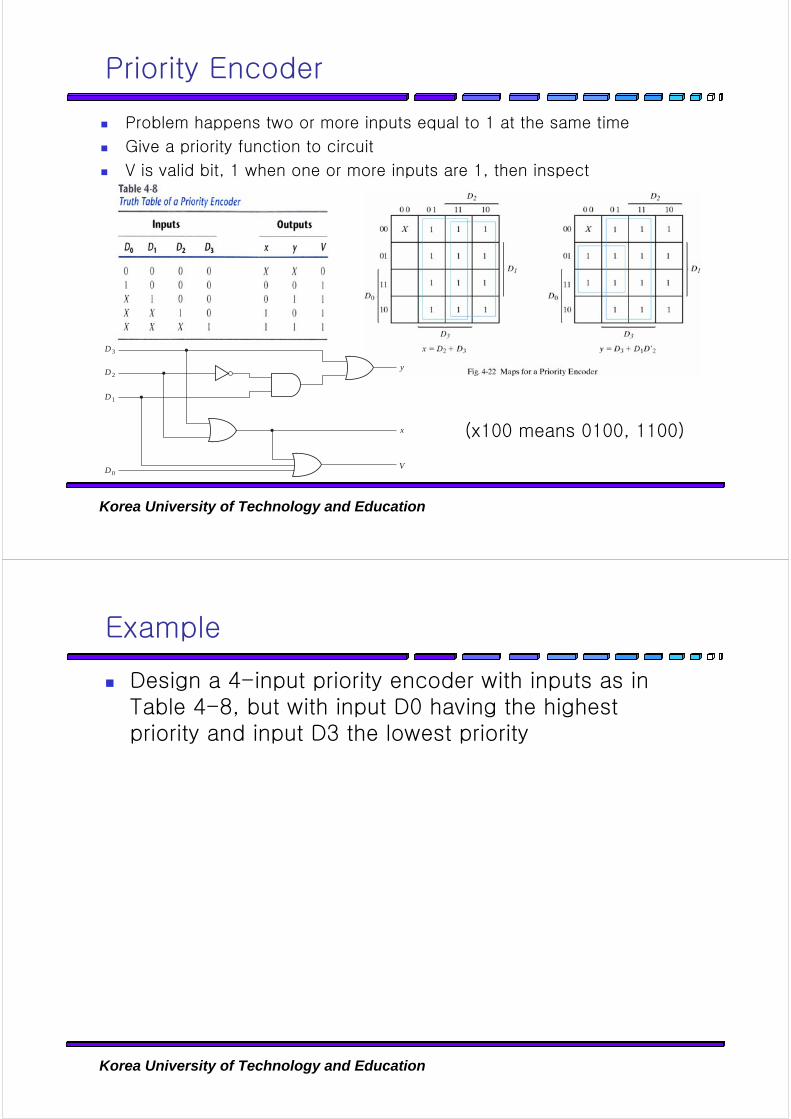
Problem happens two or more inputs equal to 1 at the same time
Give a priority function to circuit
V is valid bit, 1 when one or more inputs are 1, then inspect
(x100 means 0100, 1100)
Priority Encoder
D3
D2
D1
D0
y
x
V
Korea University of Technology and Education
Example
Design a 4-input priority encoder with inputs as in Table 4-8, but with input D0 having the highest priority and input D3 the lowest priority

Korea University of Technology and Education
Select a binary information from many input lines
Directs it to a single output line
Selection is controlled by a set of selection lines
2ⁿ input lines have n selection lines
Multiplexers
Korea University of Technology and Education
2-to-1-line Multiplexer
I0
S
Y
I1
Y
I0
I1
S
(a) Logic diagram (b) Block diagram
MUX
0
1

Korea University of Technology and Education
4-to-1-Line Multiplexer
Korea University of Technology and Education
Quadruple 2-to-1-Line Multiplexer

Korea University of Technology and Education
Boolean Function Implementation with MUX
MUX is essentially decoder includes OR gate
Minterms of function are generated in a MUX
n input variables
First n-1 variables -> input of MUX
Remaining variable -> data inputs
( ) ( )7,6,2,1,, ∑=zyxF
Korea University of Technology and Education
Boolean Function Implementation with MUX
S0
S1
S2
012
34
5
6
7
8 1 MUX
C
BA
D
F
0
1
A
0000000011111111
B
0000111100001111
C
0011001100110011
D
0101010101010101
F
0101100000011111
F D
F D
F D
F 0
F 0
F D
F 1
F 1

Korea University of Technology and Education
Three-state gatesLogic 1, 0 and high-impedance state
High-impedance state behaves like an open circuit
Three-state Gates
Korea University of Technology and Education
Multiplexers can be constructed with three-state gates
MUX with Three-state Gates