chapter_4
3
4. SYSTEM ANALYSIS Banking services on social media Page 15 4.1 DOMAIN ANALYSIS Domain analysis is the first phase of domain engineering. It is a key method for realizing systematic software reuse. Domain analysis produces domain models using methodologies such as domain specific languages, feature tables, facet tables, facet templates, and generic architectures, which describe all of the systems in a domain. Several methodologies for domain analysis have been proposed. The products, or "artifacts", of a domain analysis are sometimes object-oriented models (e.g. represented with the Unified Modeling Language (UML)) or data models represented with entity-relationship diagrams (ERD). Software developers can use these models as a basis for the implementation of software architectures and applications. This approach to domain analysis is sometimes called model-driven engineering. 4.1.1 DOMAIN CLASS DIAGRAM A class diagram in the Unified Modeling Language (UML) is a type of static structure diagram that describes the structure of a system by showing the system's classes, their attributes, operations (or methods), and the relationships among objects. It is used both for general conceptual modeling of the systematic of the application, and for detailed modeling translating the models into programming code. Class diagrams can also be used for data modeling. The classes in a class diagram represent both the main objects, interactions in the application and the classes to be programmed. In the diagram, classes are represented with boxes which contain three parts: The top part contains the name of the class. It is printed in Bold, centered and the first letter capitalized. The middle part contains the attributes of the class. They are left aligned and the first letter is lower case. The bottom part gives the methods or operations the class can take or undertake. They are also left aligned and the first letter is lower case.
-
Upload
shailesh-jain -
Category
Documents
-
view
213 -
download
0
Transcript of chapter_4

4. SYSTEM ANALYSIS
Banking services on social media Page 15
4.1 DOMAIN ANALYSIS
Domain analysis is the first phase of domain engineering. It is a key method for realizing
systematic software reuse. Domain analysis produces domain models using methodologies such
as domain specific languages, feature tables, facet tables, facet templates, and generic
architectures, which describe all of the systems in a domain. Several methodologies for domain
analysis have been proposed.
The products, or "artifacts", of a domain analysis are sometimes object-oriented
models (e.g. represented with the Unified Modeling Language (UML)) or data models
represented with entity-relationship diagrams (ERD). Software developers can use these models
as a basis for the implementation of software architectures and applications. This approach to
domain analysis is sometimes called model-driven engineering.
4.1.1 DOMAIN CLASS DIAGRAM
A class diagram in the Unified Modeling Language (UML) is a type of static structure
diagram that describes the structure of a system by showing the system's classes, their attributes,
operations (or methods), and the relationships among objects. It is used both for
general conceptual modeling of the systematic of the application, and for detailed modeling
translating the models into programming code.
Class diagrams can also be used for data modeling. The classes in a class diagram
represent both the main objects, interactions in the application and the classes to be programmed.
In the diagram, classes are represented with boxes which contain three parts:
The top part contains the name of the class. It is printed in Bold, centered and the first letter
capitalized.
The middle part contains the attributes of the class. They are left aligned and the first letter is
lower case.
The bottom part gives the methods or operations the class can take or undertake. They are
also left aligned and the first letter is lower case.
4. System analysis
Banking services on social media Page 16
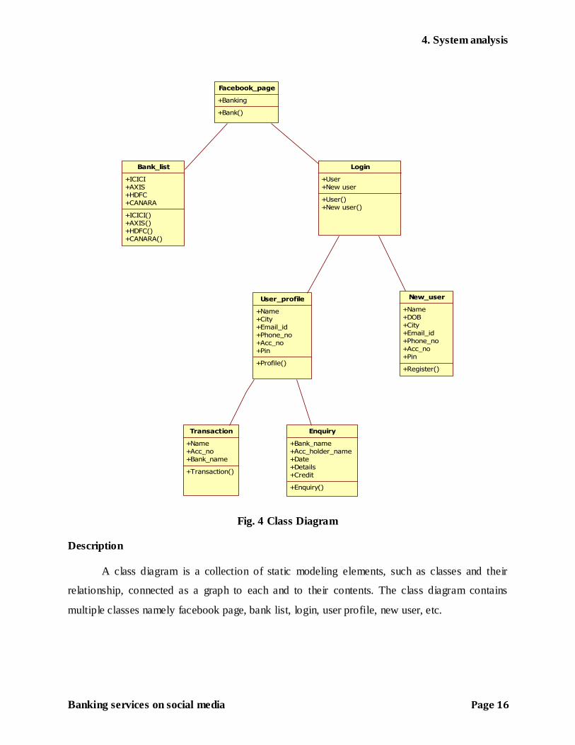
Fig. 4 Class Diagram
Description
A class diagram is a collection of static modeling elements, such as classes and their
relationship, connected as a graph to each and to their contents. The class diagram contains
multiple classes namely facebook page, bank list, login, user profile, new user, etc.
Facebook_page
+Banking
+Bank()
Login
+User
+New user
+User()
+New user()
User_profile
+Name
+City
+Email_id
+Phone_no
+Acc_no
+Pin
+Profile()
Bank_list
+ICICI
+AXIS
+HDFC
+CANARA
+ICICI()
+AXIS()
+HDFC()
+CANARA()
New_user
+Name
+DOB
+City
+Email_id
+Phone_no
+Acc_no
+Pin
+Register()
Transaction
+Name
+Acc_no
+Bank_name
+Transaction()
Enquiry
+Bank_name
+Acc_holder_name
+Date
+Details
+Credit
+Enquiry()

4. System analysis
Banking services on social media Page 17
4.2 COLLABORATION DIAGRAM
The UML Collaboration diagram is used to model how objects involved in a scenario
interact, with each object instantiating a particular class in the system. Objects are connected by
links, each link representing an instance of an association between the respective classes
involved. The link shows messages sent between the objects, and the type of message passed
(synchronous, asynchronous, simple, balking, and timeout). Collaboration diagrams offer a better
view of a scenario than a Sequence diagram when the modeler is trying to understand all of the
effects on a given object and are therefore good for procedural design. Objects are depicted on a
Collaboration diagram as rectangles. The object name is provided first, with the class name to
the right; the two names are separated by a colon.
Fig. 5 Collaboration diagram
Description
The user login on facebook and get access to banks details. The user has a onetime
password which identifies him or her and enables him to make transaction.