
Chapter Two Boundary Layer Theory Contentsuotechnology.edu.iq/dep-MechanicsandEquipment... ·...
16
Chapter Two Boundary Layer Theory Contents 1- Introduction. 2- Momentum equation for boundary layer. 3- Laminar boundary layer. 4- Turbulent boundary layer. 5- Friction drag in transition region. 6- Effect of pressure gradient. 7- Separation of flow inside duct systems. ) ﻓﻘﻂ اﻟﺘﻜﻴﻴﻒ ﻟﻔﺮع( 8- Examples. 9- Problems; sheet No. 2 1- Introduction: Development of boundary layer on a flat plate The flow of a viscous fluid on a solid surface represents a region in which velocity increases from zero at the surface and approaches the velocity of the main stream. This region is known as the boundary layer. The figure shows the development of a boundary layer on one side of a long flat plate held parallel to the flow direction.
-
Upload
phungnguyet -
Category
Documents
-
view
283 -
download
14
Transcript of Chapter Two Boundary Layer Theory Contentsuotechnology.edu.iq/dep-MechanicsandEquipment... ·...
Chapter Two
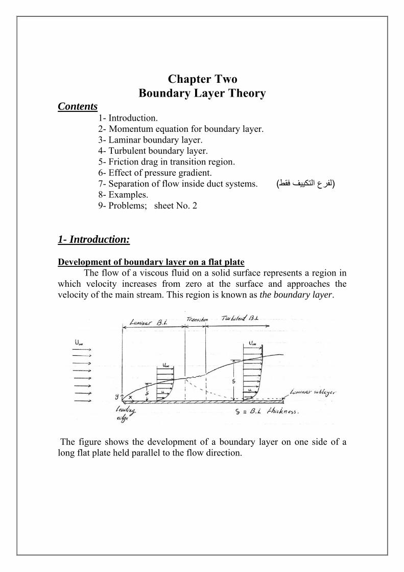
Boundary Layer Theory Contents 1- Introduction. 2- Momentum equation for boundary layer. 3- Laminar boundary layer. 4- Turbulent boundary layer. 5- Friction drag in transition region. 6- Effect of pressure gradient. 7- Separation of flow inside duct systems. )لفرع التكييف فقط ( 8- Examples. 9- Problems; sheet No. 2 1- Introduction: Development of boundary layer on a flat plate The flow of a viscous fluid on a solid surface represents a region in which velocity increases from zero at the surface and approaches the velocity of the main stream. This region is known as the boundary layer.
The figure shows the development of a boundary layer on one side of a long flat plate held parallel to the flow direction.
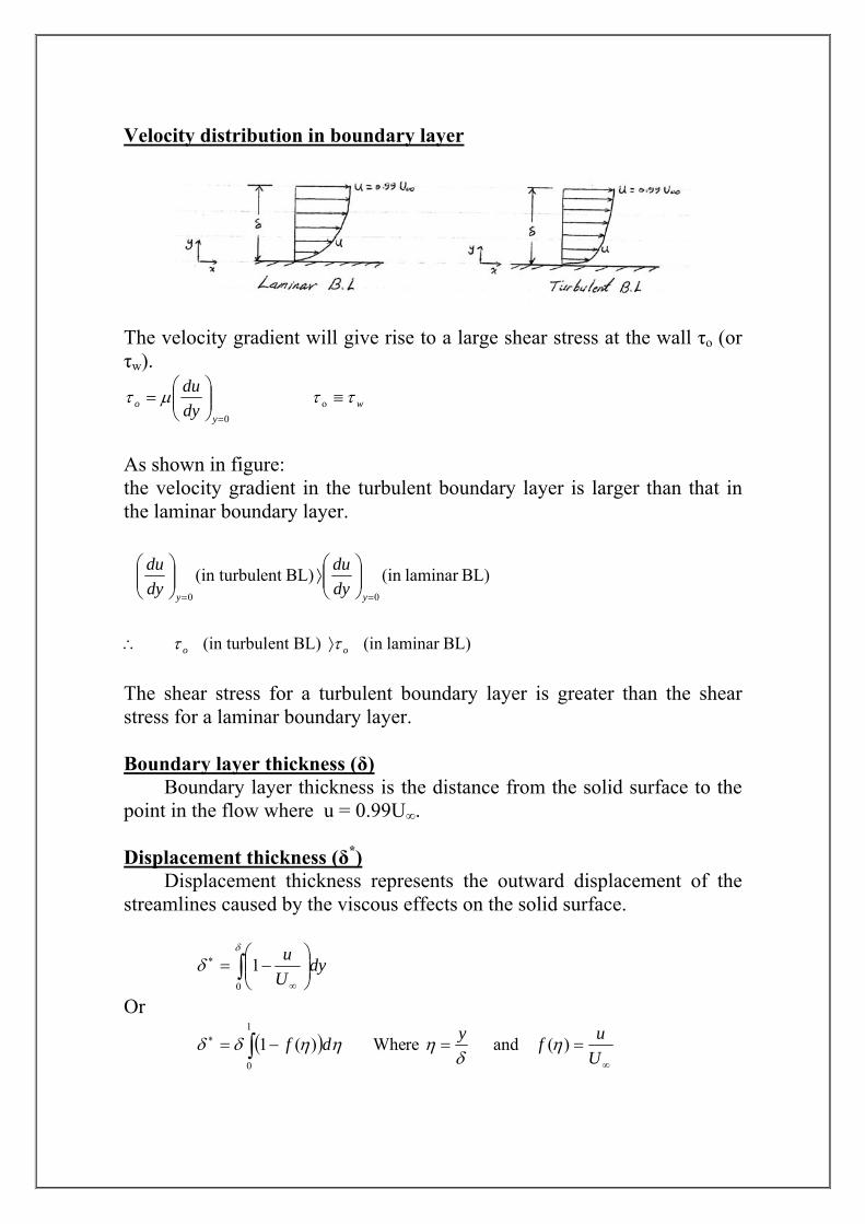
Velocity distribution in boundary layer
The velocity gradient will give rise to a large shear stress at the wall τo (or τw).
wy
o dydu ττμτ ≡⎟⎟
⎠
⎞⎜⎜⎝
⎛=
=o
0
As shown in figure: the velocity gradient in the turbulent boundary layer is larger than that in the laminar boundary layer.
BL)laminar (in BL)ent (in turbul00 ==
⎟⎟⎠
⎞⎜⎜⎝
⎛⟩⎟⎟
⎠
⎞⎜⎜⎝
⎛
yy dydu
dydu
BL)laminar (in BL)ent (in turbul oo ττ ⟩∴
The shear stress for a turbulent boundary layer is greater than the shear stress for a laminar boundary layer. Boundary layer thickness (δ) Boundary layer thickness is the distance from the solid surface to the point in the flow where u = 0.99U∞. Displacement thickness (δ*) Displacement thickness represents the outward displacement of the streamlines caused by the viscous effects on the solid surface.
∫ ⎟⎟⎠
⎞⎜⎜⎝
⎛−=
∞
∗δ
δ0
1 dyUu
Or
( )∫∞
∗ ==−=1
0
)( and re Whe)(1Uufydf η
δηηηδδ
Momentum thickness (θ) Momentum thickness, is defined as the thickness of a layer of fluid , with velocity U∞ , for which the momentum flux is equal to the deficit of momentum flux through the boundary layer.
∫ ⎟⎟⎠
⎞⎜⎜⎝
⎛−=
∞∞
δ
θ0
1 dyUu
Uu
Or
( )∫ −=1
0
)(1)( ηηηδθ dff
Shape factor (H) H is a velocity profile shape factor.
θδ ∗
=H
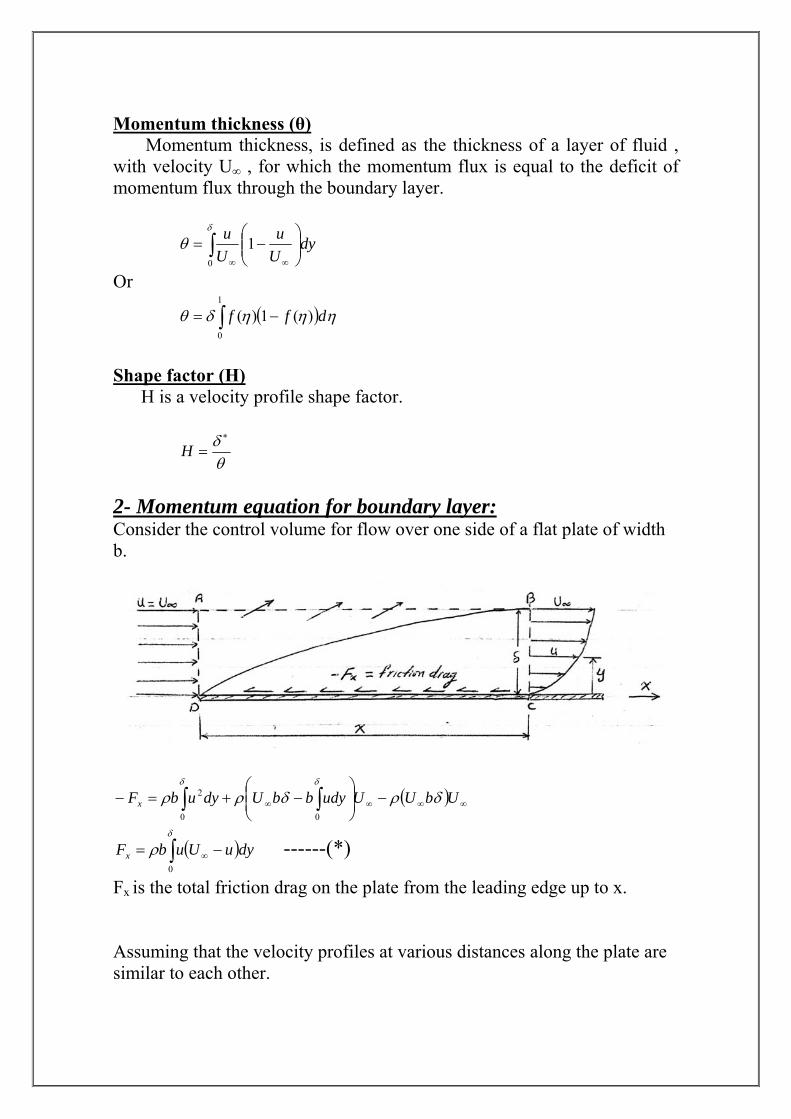
2- Momentum equation for boundary layer: Consider the control volume for flow over one side of a flat plate of width b.
( )∫ ∫ ∞∞∞∞ −⎟⎟⎠
⎞⎜⎜⎝
⎛−+=−
δ δ
δρδρρ0 0
2 UbUUudybbUdyubFx
( )∫ −= ∞
δ
ρ0
dyuUubFx ------(*)
Fx is the total friction drag on the plate from the leading edge up to x. Assuming that the velocity profiles at various distances along the plate are similar to each other.
( )
δη
ηδ
y
fyfUu
=
=⎟⎠⎞
⎜⎝⎛=
∞
where
Equation (*) may be written as:
( )∫ −=
= ∞
1
0
2
)(1)(
where-(1)-----
ηηηα
δαρ
dff
bUFx
The local wall shear stress is :
Equations (1) and (2) are valid for either laminar or turbulent flow in the boundary layer. 3- Laminar boundary layer: The wall shear stress:
0=⎟⎟⎠
⎞⎜⎜⎝
⎛=
yo dy
duμτ
Let 0
)(
=⎥⎦
⎤⎢⎣
⎡=
ηηηβ
ddf
δβμ
τ ∞=⇒U
o
Another expression for shear stress:
fo cU 2
21
∞= ρτ
Where cf = local friction coefficient.
-(2)----- 2
dxdUoδαρτ ∞=
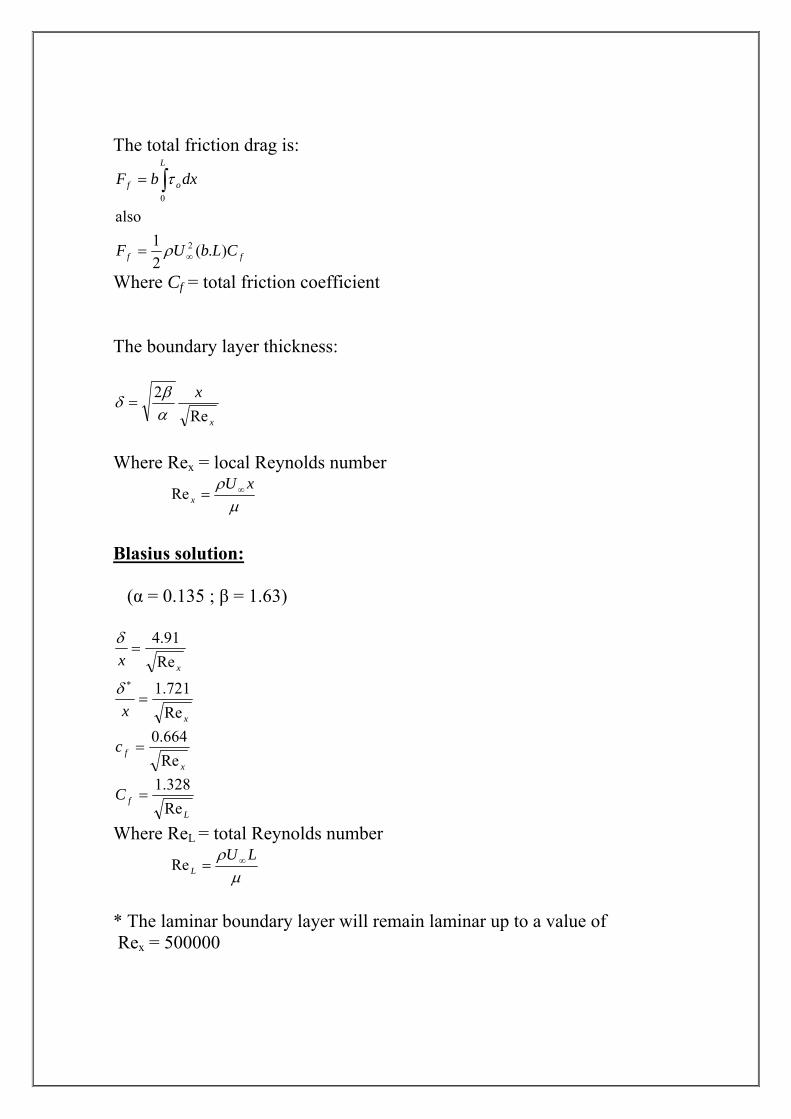
The total friction drag is:
ff
L
of
CLbUF
dxbF
).(21
also
2
0
∞=
= ∫
ρ
τ
Where Cf = total friction coefficient The boundary layer thickness:
x
xRe
2αβδ =
Where Rex = local Reynolds number
μ
ρ xUx
∞=Re
Blasius solution: (α = 0.135 ; β = 1.63)
xx Re91.4
=δ
xx Re721.1
=∗δ
xfc
Re664.0
=
LfC
Re328.1
=
Where ReL = total Reynolds number
μ
ρ LUL
∞=Re
* The laminar boundary layer will remain laminar up to a value of Rex = 500000
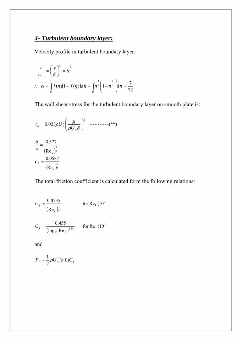
4- Turbulent boundary layer: Velocity profile in turbulent boundary layer:
71
71
ηδ
=⎟⎠⎞
⎜⎝⎛=
∞
yUu
( )∫ ∫ =⎟⎟⎠
⎞⎜⎜⎝
⎛−=−=∴
1
0
1
0
71
71
7271)(1)( ηηηηηηα ddff
The wall shear stress for the turbulent boundary layer on smooth plate is:
-(**)------- 023.041
2⎟⎟⎠
⎞⎜⎜⎝
⎛=
∞∞ δρ
μρτU
Uo
( )
( )51
51
Re
0587.0Re
377.0
x
f
x
c
x
=
=δ
The total friction coefficient is calculated form the following relations:
( )7
L51 10Refor
Re
0735.0⟨=
L
fC
( )7
L58.210
10Refor Relog455.0
⟩=L
fC
and
ff CLbUF ).(21 2
∞= ρ
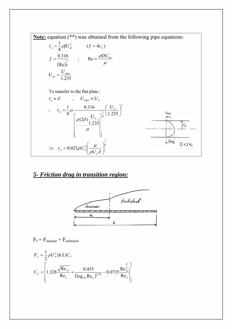
Note: equation (**) was obtained from the following pipe equations:
( )
41
2
2
41
max
max
41
2
023.0
235.1
235.1)2(
316.081
, :plateflat theto transfer To
235.1
Re ; Re
316.0
)4( 81
⎟⎟⎠
⎞⎜⎜⎝
⎛=⇒
⎟⎠⎞
⎜⎝⎛
⎥⎥⎥⎥
⎦
⎤
⎢⎢⎢⎢
⎣
⎡=∴
≈≈
=
==
==
∞∞
∞
∞
∞
δρμρτ
μ
δρ
ρτ
δ
μρ
ρτ
UU
U
U
UUr
UU
DUf
cffU
o
o
o
av
av
favo
5- Friction drag in transition region:
Ff = Flaminar + Fturbulent
( ) ⎥⎥⎥
⎦
⎤
⎢⎢⎢
⎣
⎡−+=
= ∞
L
xc
LL
xcf
ff
C
CLbUF
ReRe
0735.0Relog455.0
ReRe
328.1
).(21
54
58.210
2ρ
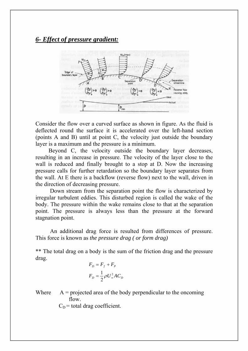
6- Effect of pressure gradient:
Consider the flow over a curved surface as shown in figure. As the fluid is deflected round the surface it is accelerated over the left-hand section (points A and B) until at point C, the velocity just outside the boundary layer is a maximum and the pressure is a minimum. Beyond C, the velocity outside the boundary layer decreases, resulting in an increase in pressure. The velocity of the layer close to the wall is reduced and finally brought to a stop at D. Now the increasing pressure calls for further retardation so the boundary layer separates from the wall. At E there is a backflow (reverse flow) next to the wall, driven in the direction of decreasing pressure. Down stream from the separation point the flow is characterized by irregular turbulent eddies. This disturbed region is called the wake of the body. The pressure within the wake remains close to that at the separation point. The pressure is always less than the pressure at the forward stagnation point. An additional drag force is resulted from differences of pressure. This force is known as the pressure drag ( or form drag) ** The total drag on a body is the sum of the friction drag and the pressure drag.
DD
PfD
ACUF
FFF
2
21
∞=
+=
ρ
Where A = projected area of the body perpendicular to the oncoming flow. CD = total drag coefficient.
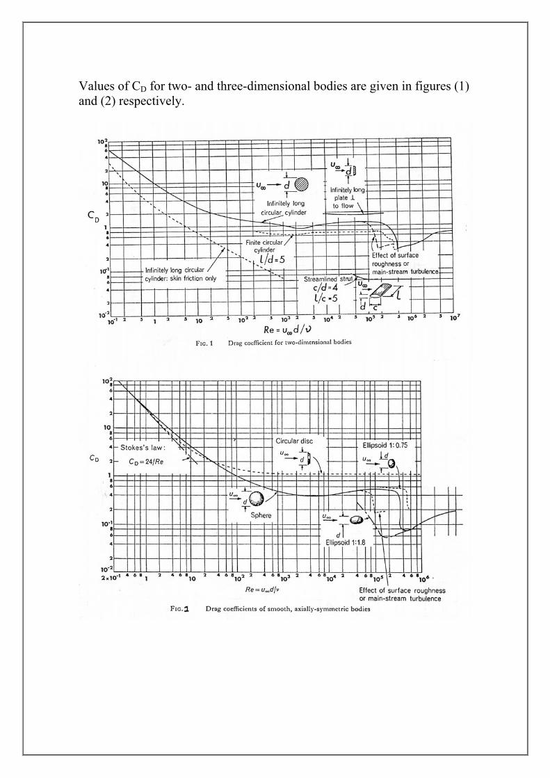
Values of CD for two- and three-dimensional bodies are given in figures (1) and (2) respectively.
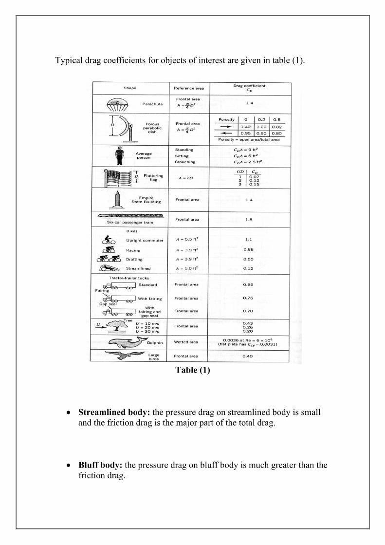
Typical drag coefficients for objects of interest are given in table (1).
Table (1)
• Streamlined body: the pressure drag on streamlined body is small
and the friction drag is the major part of the total drag.
• Bluff body: the pressure drag on bluff body is much greater than the
friction drag.
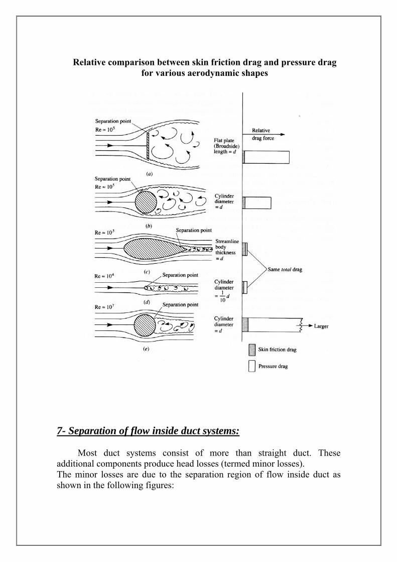
Relative comparison between skin friction drag and pressure drag for various aerodynamic shapes
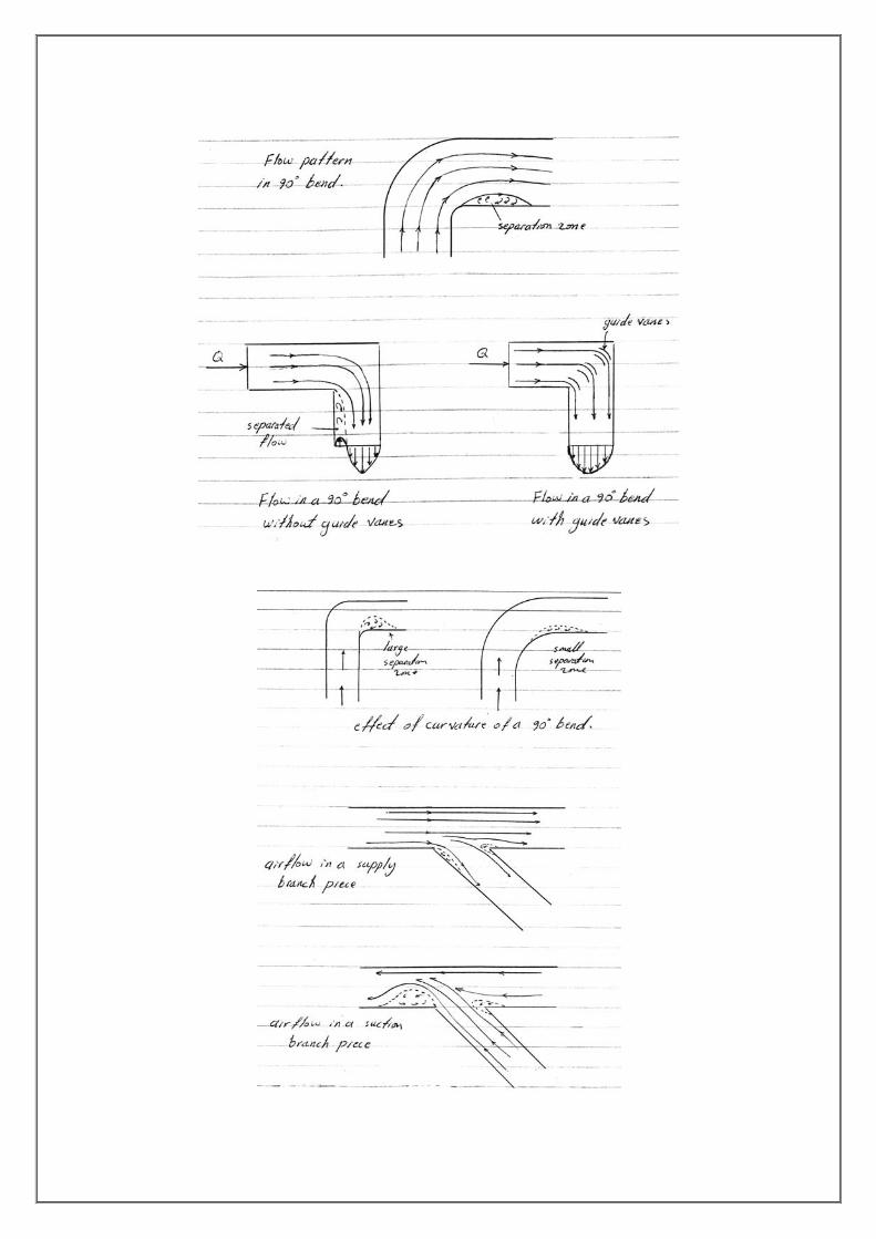
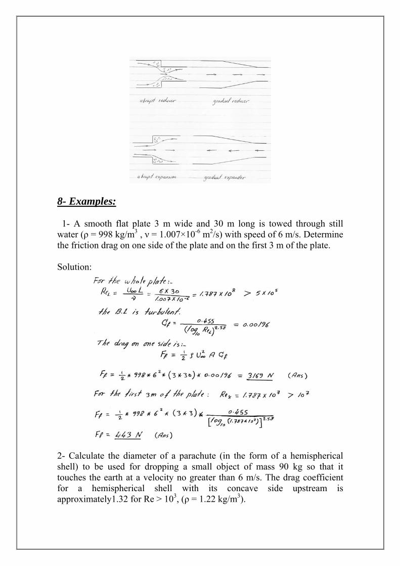
- Separation of flow inside duct systems:
7
Most duct systems consist of more than straight duct. These
duct as
additional components produce head losses (termed minor losses). The minor losses are due to the separation region of flow insideshown in the following figures:
8- Examples: 1- A smooth flat plate 3 m wide and 30 m long is towed through still water (ρ = 998 kg/m3 , ν = 1.007×10⁻⁶ m2/s) with speed of 6 m/s. Determine the friction drag on one side of the plate and on the first 3 m of the plate. Solution:
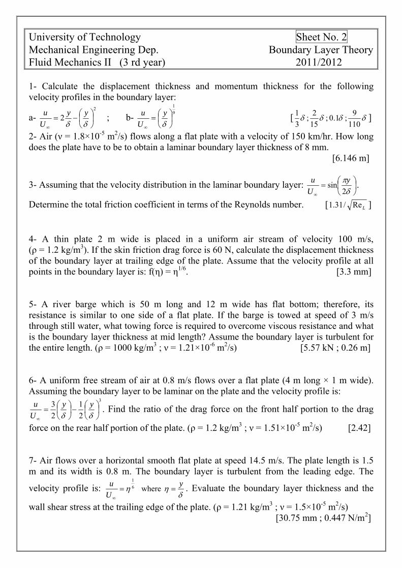
2- Calculate the diameter of a parachute (in the form of a hemispherical shell) to be used for dropping a small object of mass 90 kg so that it touches the earth at a velocity no greater than 6 m/s. The drag coefficient
r a hemispherical shell with its concave side upstream is tely1.32 for Re > 103, (ρ = 1.22 kg/m3).
foapproxima
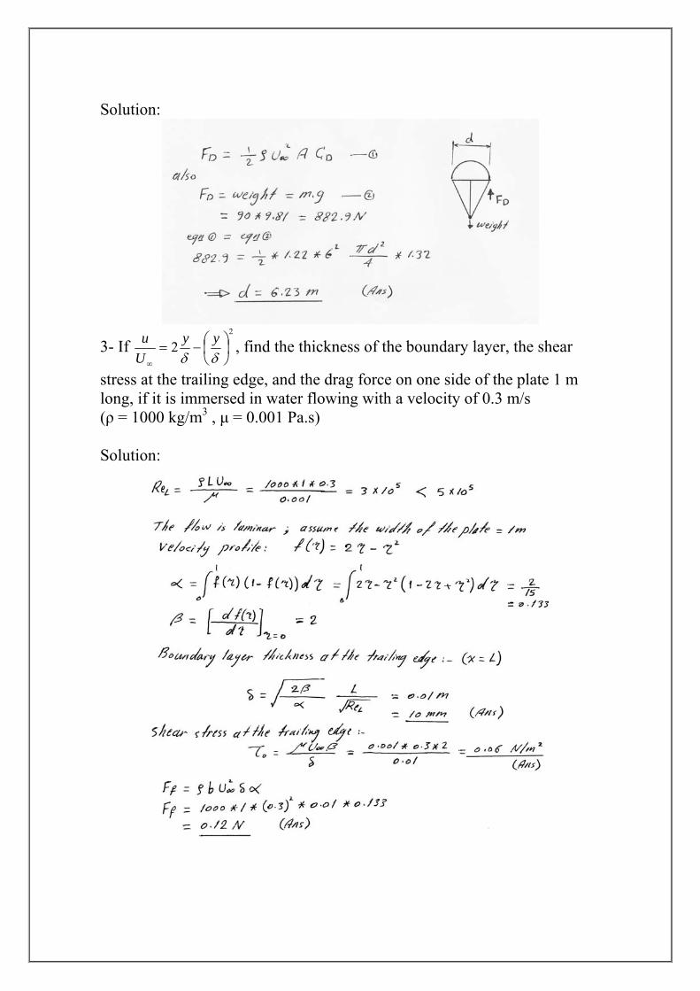
Solution:
2
2 ⎟⎠⎞
⎜⎝⎛−=
∞ δδyy
Uu3- If , find the thickness of the boundary layer, the shear
stress at the trailing edge, and the drag force on one side of the plate 1 m long, if it is immersed in water flowing with a velocity of 0.3 m/s (ρ = 1000 kg/m3 , μ = 0.001 Pa.s) Solution:
University of Technology Sheet No. 2 Mechanical Engineering Dep. Boundary Layer Theory Fluid Mechanics II (3 rd year) 2011/2012 1- Calculate the displacement thickness and momentum thickness for the following velocity profiles in the boundary layer:
a- ; b- 91
⎟⎠⎞
⎜⎝⎛=
∞ δy
Uu2
2 ⎟⎠⎞
⎜⎝⎛−=
∞ δδyy
Uu [ δδδδ
1109 ; 1.0 ;
152 ;
31 ]
2- Air (ν = 1.8×10⁻⁵ m2/s) flows along a flat plate with a velocity of 150 km/hr. How long does the plate have to be to obtain a laminar boundary layer thickness of 8 mm. [6.146 m]
3- Assuming that the velocity distribution in the laminar boundary layer: ⎟⎠⎞
⎜⎝⎛=δπ2
sin y . ∞U
u
Determine the total friction coefficient in terms of the Reynolds number. [ LRe/31.1 ] 4- A thin plate 2 m wide is placed in a uniform air stream of velocity 100 m/s, (ρ = 1.2 kg/m3). If the skin friction drag force is 60 N, calculate the displacement thickness of the boundary layer at trailing edge of the plate. Assume that the velocity profile at all points in the boundary layer is: f(η) = η1/6. [3.3 mm] 5- A river barge which is 50 m long and 12 m wide has flat bottom; therefore, its resistance is similar to one side of a flat plate. If the barge is towed at speed of 3 m/s through still water, what towing force is required to overcome viscous resistance and what is the boundary layer thickness at mid length? Assume the boundary layer is turbulent for the entire length. (ρ = 1000 kg/m3 ; ν = 1.21×10⁻⁶ m2/s) [5.57 kN ; 0.26 m] 6- A uniform free stream of air at 0.8 m/s flows over a flat plate (4 m long × 1 m wide). Assuming the boundary layer to be laminar on the plate and the velocity profile is:
3
21
23
⎟⎠⎞
⎜⎝⎛−⎟
⎠⎞
⎜⎝⎛=
∞ δδyy
Uu . Find the ratio of the drag force on the front half portion to the drag
force on the rear half portion of the plate. (ρ = 1.2 kg/m3 ; ν = 1.51×10⁻⁵ m2/s) [2.42] 7- Air flows over a horizontal smooth flat plate at speed 14.5 m/s. The plate length is 1.5 m and its width is 0.8 m. The boundary layer is turbulent from the leading edge. The
velocity profile is: δ
ηη yUu
==∞
where61
. Evaluate the boundary layer thickness and the
wall shear stress at the trailing edge of the plate. (ρ = 1.21 kg/m3 ; ν = 1.5×10⁻⁵ m2/s) [30.75 mm ; 0.447 N/m2]
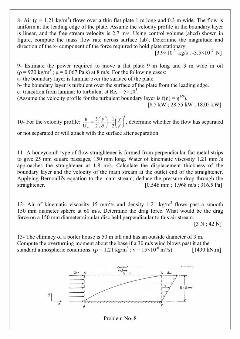
8- Air (ρ = 1.21 kg/m3) flows over a thin flat plate 1 m long and 0.3 m wide. The flow is
de and irection of the x- component of the force required to hold plate stationary.
ate the power required to m wide in oil 920 kg/m3 ; μ .s) at 8 m
[8.5 kW ; 28.55 kW ; 18.05 kW]
uniform at the leading edge of the plate. Assume the velocity profile in the boundary layer own in is linear, and the free stream velocity is 2.7 m/s. Using control volume (abcd) sh
figure, compute the mass flow rate across surface (ab). Determine the magnitud [3.9×10⁻³ kg/s ; -3.5×10⁻³ N] 9- Estim ove a flat plate 9 m long and 3 m(ρ = = 0.067 Pa /s. For the following cases: a- the boundary layer is laminar over the surface of the plate. b- the boundary layer is turbulent over the surface of the plate from the leading edge.
5c- transition from laminar to turbulent at Rec = 5×10 . Assume the velocity profile for the turbulent boundary layer is f(η) = η1/9). (
3
21
23
⎟⎠⎞
⎜⎝⎛−⎟
⎠⎞
⎜⎝⎛=
δδyy
Uu , determine whether the flow ha d 10- For the velocity profile: ∞
s separate
r not separated or will attach with the surface after separation.
/oundary layer and the velocity of the main stream at the outlet end of the straightener.
rce on a 150 mm diameter circular disc held perpendicular to this air stream.
Compute the overtustandard atmospheric conditions. (ρ = 1.21 kg/m ; ν = 15×10 m /s) [1430 kN.m]
o 11- A honeycomb type of flow straightener is formed from perpendicular flat metal strips to give 25 mm square passages, 150 mm long. Water of kinematic viscosity 1.21 mm2/s pproaches the straightener at 1.8 m s. Calculate the displacement thickness of the a
bApplying Bernoulli's equation to the main stream, deduce the pressure drop through the straightener. [0.546 mm ; 1.968 m/s ; 316.5 Pa] 12- Air of kinematic viscosity 15 mm2/s and density 1.21 kg/m3 flows past a smooth
50 mm diameter sphere at 60 m/s. Determine the drag force. What would be the drag 1of
[3 N ; 42 N] 13- The chimney of a boiler house is 50 m tall and has an outside diameter of 3 m.
rning moment about the base if a 30 m/s wind blows past it at the 3 -6 2
Problem No. 8