
CHAPTER Supporting Hard Drives - CoffeeCup Software
62
329 Supporting Hard Drives • About the technologies used inside a hard drive and how data is organized on the drive • How a computer communicates with a hard drive • How hard drives can work together in a RAID array • About floppy drives • How to select and install a hard drive • How to solve hard drive problems In this chapter, you will learn: CHAPTER 8 T he hard drive is the most important secondary storage device in a computer, and supporting hard drives is one of the more important tasks of a PC support technician. This chapter introduces the different kinds of hard drive technologies that have accounted for the continual upward increase in hard drive capacities and speeds over the past few years. The ways a computer interfaces with a hard drive have also changed several times over the years as both the computer and hard drives improve the technologies and techniques for communication. In this chapter, you will learn about past and present methods of communication between the computer and drive so that you can support both older and newer drives. Floppy drives are becoming obsolete, but they have not completely disappeared. In this chapter, you’ll learn just enough about them to know how to support this older technology. One benefit to studying floppy drives is that they are similar in design to hard drives and yet much easier to understand. Therefore, they can be a great aid in understanding how hard drives work. Finally, you’ll learn how to install the different types of hard drives and what to do if you have problems with a hard drive.
Transcript of CHAPTER Supporting Hard Drives - CoffeeCup Software
329
Supporting Hard Drives
• About thetechnologies usedinside a harddrive and howdata is organizedon the drive
• How a computercommunicateswith a hard drive
• How hard drivescan worktogether in aRAID array
• About floppydrives
• How to selectand install a hard drive
• How to solvehard drive problems
In this chapter,you will learn:
CHAPTER
8
The hard drive is the most important secondary storage device in a computer, and supporting hard drives is one of the more
important tasks of a PC support technician. This chapter introducesthe different kinds of hard drive technologies that have accounted forthe continual upward increase in hard drive capacities and speedsover the past few years. The ways a computer interfaces with a harddrive have also changed several times over the years as both thecomputer and hard drives improve the technologies and techniquesfor communication. In this chapter, you will learn about past andpresent methods of communication between the computer and driveso that you can support both older and newer drives.
Floppy drives are becoming obsolete, but they have not completelydisappeared. In this chapter, you’ll learn just enough about them toknow how to support this older technology. One benefit to studyingfloppy drives is that they are similar in design to hard drives and yetmuch easier to understand. Therefore, they can be a great aid inunderstanding how hard drives work. Finally, you’ll learn how toinstall the different types of hard drives and what to do if you haveproblems with a hard drive.
CHAPTER 8330 Supporting Hard Drives
1.8" solid-state drive
Inside anSSD drive
2.5" solid-state drive
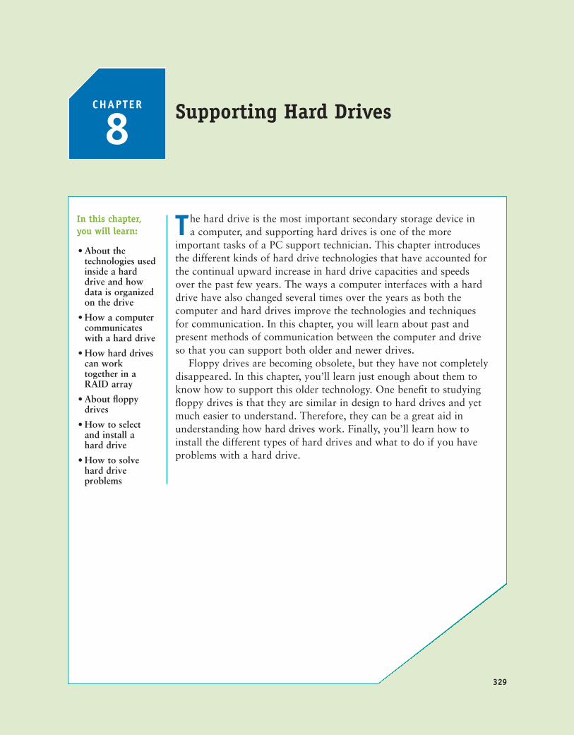
Figure 8-1 Solid state drives by ToshibaCourtesy of Toshiba America Electronic Components
INSIDE A HARD DRIVE
A hard disk drive (HDD), most often called a hard drive, comes in two sizes for personalcomputers: the 2.5" size is used for laptop computers and the 3.5" size is used for desktops.In addition, a smaller 1.8" size (about the size of a credit card) hard drive is used in somelow-end laptops and other equipment such as MP3 players.
All three sizes of hard drives use the same types of hardware technologies inside the drive:solid state or magnetic. In addition, some drives use a combination of both technologies. As a support technician, you need to understand a little about solid state and magnetictechnologies, and you also need to know how data is organized inside a hard drive. Bothtopics are covered in this part of the chapter.
SOLID STATE, MAGNETIC, AND HYBRID DRIVESInside the drive housing, two types of technologies can be used: solid state and magnetic. A solidstate drive (SSD), also called a solid state device (SSD), is called solid state because it has no movingparts. The drives are built using nonvolatile flash memory, which is similar to that used for USBflash drives. Recall from Chapter 1 that nonvolatile memory does not lose its data even after thepower is turned off. Because the technology is expensive, solid state drives are currently 2.5" drivesused only in laptop computers. However, by the time this book is in print, it is expected that solidstate external hard drives and solid state drives for desktop computers will be available. Figure 8-1shows two sizes of solid state drives (2.5" and 1.8") and what the inside of an SSD hard drivelooks like. Solid state hard drives cost more and are more rugged than magnetic hard drives.Because they have no moving parts, they also last longer, use less power, and are more reliable.
A+220-7011.1
A magnetic hard drive has one, two, or more platters, or disks, that stack together and spinin unison inside a sealed metal housing that contains firmware to control reading and writingdata to the drive and to communicate with the motherboard. The top and bottom of each diskhave a read/write head that moves across the disk surface as all the disks rotate on a spindle
331Inside a Hard Drive
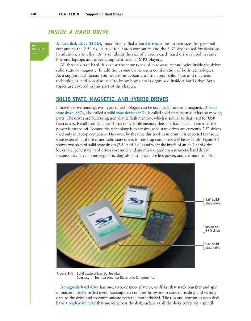
8Read-write head
Platters or disks
Drive spindle
Actuator
Figure 8-2 Inside a hard driveCourtesy: Course Technology/Cengage Learning
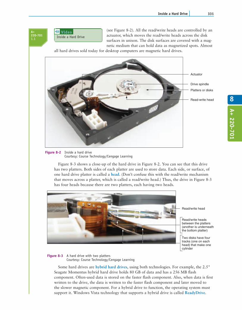
Two disks have fourtracks (one on eachhead) that make onecylinder
Read/write headsbetween the platters(another is underneaththe bottom platter)
Read/write head
Figure 8-3 A hard drive with two plattersCourtesy: Course Technology/Cengage Learning
(see Figure 8-2). All the read/write heads are controlled by anactuator, which moves the read/write heads across the disksurfaces in unison. The disk surfaces are covered with a mag-netic medium that can hold data as magnetized spots. Almost
all hard drives sold today for desktop computers are magnetic hard drives.
Figure 8-3 shows a close-up of the hard drive in Figure 8-2. You can see that this drivehas two platters. Both sides of each platter are used to store data. Each side, or surface, ofone hard drive platter is called a head. (Don’t confuse this with the read/write mechanismthat moves across a platter, which is called a read/write head.) Thus, the drive in Figure 8-3has four heads because there are two platters, each having two heads.
Some hard drives are hybrid hard drives, using both technologies. For example, the 2.5"Seagate Momentus hybrid hard drive holds 80 GB of data and has a 256 MB flashcomponent. Often-used data is stored on the faster flash component. Also, when data is firstwritten to the drive, the data is written to the faster flash component and later moved to the slower magnetic component. For a hybrid drive to function, the operating system mustsupport it. Windows Vista technology that supports a hybrid drive is called ReadyDrive.
A+ 220-701
A+220-7011.1 Inside a Hard Drive
Video

CHAPTER 8332 Supporting Hard Drives
One sector
One track
Figure 8-4 A hard drive or floppy disk is divided into tracks and sectors; several sectors make one clusterCourtesy: Course Technology/Cengage Learning
Figure 8-5 The bottom of a hard drive shows the circuit board that contains the firmware that controls the driveCourtesy: Course Technology/Cengage Learning
HOW DATA IS ORGANIZED ON A HARD DRIVEEach disk surface on a hard drive is divided into concentric circles, called tracks. Recallfrom Chapter 5 that each track is further divided into 512-byte segments called sectors (also called records). All the tracks that are the same distance from the center of the plattersmake up one cylinder. Track and sector markings (see Figure 8-4) are written to a hard drivebefore it leaves the factory in a process called low-level formatting. The total number ofsectors on the drive determines the drive capacity. Today’s drive capacities are usuallymeasured in GB (gigabytes) or TB (terabytes, each of which is 1,024 gigabytes).
Firmware on a circuit board inside the drive housing is responsible for writing andreading data to these tracks and sectors and for keeping track of where everything is storedon the drive. Figure 8-5 shows the bottom side of a hard drive, which has this circuit boardexposed. Some drives protect the board inside the drive housing. BIOS and the OS use asimple sequential numbering system called logical block addressing (LBA) to address all thesectors on the hard drive without regard to where these sectors are located.

333Inside a Hard Drive
8
When a hard drive is first installed in a system, Windows initializes the drive and identi-fies it as a basic disk. A basic disk is a single hard drive that works independently of otherhard drives. The initializing process writes a Master Boot Record (MBR) to the drive. Recallfrom Chapter 5 that the MBR is the first sector at the beginning of a hard drive (512 bytes).It contains two items:
The master boot program (446 bytes), which loads the OS boot program stored in the OS boot record. (This program begins the process of loading the OS.)The partition table, which contains the description, location, and size of each partition on the drive. For Windows-based systems, the MBR has space for four 16-byte entries that are used to define up to four partitions on the drive. For each partition, the 16 bytes are used to hold the beginning and ending location of the partition, the number of sectors in the partition, and whether or not the partition is bootable. The one bootable partition is called the active partition.
The next step is to create a partition on the drive in a process called high-level formatting or operating system formatting. During this process, you specify the size ofthe partition and what file system it will use. A partition can be a primary partition oran extended partition. A primary partition is also called a volume or a simple volume.The volume is assigned a drive letter (such as drive C: or drive D:) and is formattedusing a file system. A file system is the overall structure an OS uses to name, store, andorganize files on a drive. In a file system, a cluster is the smallest unit of space on a diskfor storing a file and is made up of one or more sectors. A file system tracks how theseclusters are used for each file stored on the disk. The active partition is always a primarypartition.
One of the four partitions on a drive can be an extended partition (see Figure 8-6).An extended partition can be divided into one or more logical drives. Each logicaldrive is assigned a drive letter (such as drive G:) and is formatted using its own filesystem.
Hard Drive with four partitions
Volume C:Formatted with
NTFS file system
Volume D:Formatted with
NTFS file system
Volume E:Formatted with
NTFS file system
Logical drive F:Formatted with
NTFS file system
Logical drive G:Formatted with
NTFS file system
Master boot record contains the partition table
Primary partition Primary partition Primary partition Extended partition
Figure 8-6 A hard drive with four partitions; the fourth partition is an extended partitionCourtesy: Course Technology/Cengage Learning
A+ 220-701
CHAPTER 8334 Supporting Hard Drives
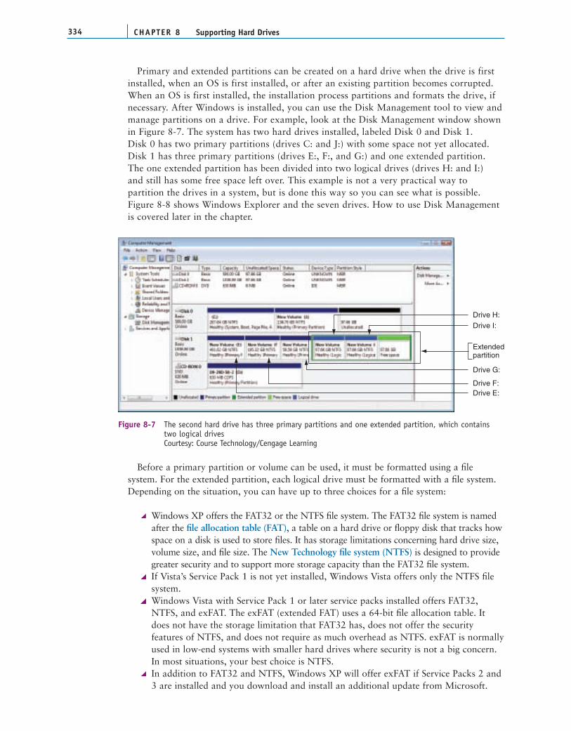
Extendedpartition
Drive G:
Drive I:Drive H:
Drive F:Drive E:
Figure 8-7 The second hard drive has three primary partitions and one extended partition, which containstwo logical drivesCourtesy: Course Technology/Cengage Learning
Primary and extended partitions can be created on a hard drive when the drive is firstinstalled, when an OS is first installed, or after an existing partition becomes corrupted.When an OS is first installed, the installation process partitions and formats the drive, ifnecessary. After Windows is installed, you can use the Disk Management tool to view andmanage partitions on a drive. For example, look at the Disk Management window shownin Figure 8-7. The system has two hard drives installed, labeled Disk 0 and Disk 1. Disk 0 has two primary partitions (drives C: and J:) with some space not yet allocated.Disk 1 has three primary partitions (drives E:, F:, and G:) and one extended partition. The one extended partition has been divided into two logical drives (drives H: and I:) and still has some free space left over. This example is not a very practical way to partition the drives in a system, but is done this way so you can see what is possible.Figure 8-8 shows Windows Explorer and the seven drives. How to use Disk Managementis covered later in the chapter.
Before a primary partition or volume can be used, it must be formatted using a filesystem. For the extended partition, each logical drive must be formatted with a file system.Depending on the situation, you can have up to three choices for a file system:
Windows XP offers the FAT32 or the NTFS file system. The FAT32 file system is namedafter the file allocation table (FAT), a table on a hard drive or floppy disk that tracks howspace on a disk is used to store files. It has storage limitations concerning hard drive size,volume size, and file size. The New Technology file system (NTFS) is designed to providegreater security and to support more storage capacity than the FAT32 file system.If Vista’s Service Pack 1 is not yet installed, Windows Vista offers only the NTFS filesystem.Windows Vista with Service Pack 1 or later service packs installed offers FAT32,NTFS, and exFAT. The exFAT (extended FAT) uses a 64-bit file allocation table. Itdoes not have the storage limitation that FAT32 has, does not offer the securityfeatures of NTFS, and does not require as much overhead as NTFS. exFAT is normallyused in low-end systems with smaller hard drives where security is not a big concern.In most situations, your best choice is NTFS.In addition to FAT32 and NTFS, Windows XP will offer exFAT if Service Packs 2 and3 are installed and you download and install an additional update from Microsoft.

335Hard Drive Interface Standards
8
Figure 8-8 Windows Explorer shows five volumes and two logical drivesCourtesy: Course Technology/Cengage Learning
Now that you have a general understanding of how hard drives work and how the OS organizes data on the drive, let’s turn our attention to how the drive’s firmwarecommunicates with the motherboard.
HARD DRIVE INTERFACE STANDARDS
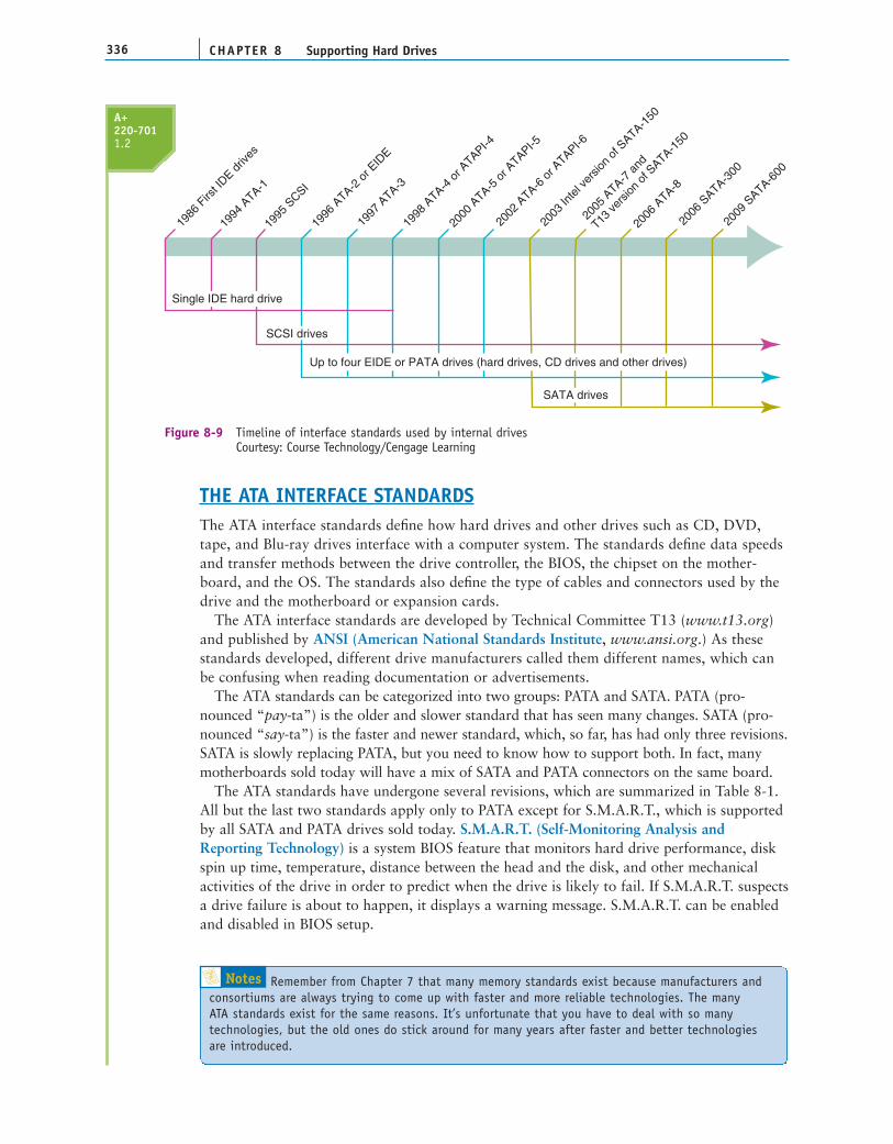
Hard drives have different ways to interface with the computer. Some standards competewith others and each type of interface standard has evolved over time, which can make for aconfusing mess of standards. To help keep them all straight, use Figure 8-9 as your guidelinefor the standards used by internal drives.
The three current methods used by internal hard drivesare Parallel ATA (PATA), Serial ATA (SATA), and SCSI.External hard drives can connect to a computer by way of external SATA (eSATA), SCSI, FireWire, USB, or a
variation of SCSI called Fibre Channel. Currently, the most popular solutions for exter-nal hard drives are USB and FireWire, which you will learn about in Chapter 9. All theother interface standards are discussed in this section. By far, the most popular standardsfor internal drives are the ATA standards, so we begin there.
A+ 220-701
A+220-7011.2
Notes In technical documentation, you might see a hard drive abbreviated as HDD (hard disk drive).However, this chapter uses the term “hard drive.”
Examining Hard DrivesVideo
THE ATA INTERFACE STANDARDSThe ATA interface standards define how hard drives and other drives such as CD, DVD,tape, and Blu-ray drives interface with a computer system. The standards define data speedsand transfer methods between the drive controller, the BIOS, the chipset on the mother-board, and the OS. The standards also define the type of cables and connectors used by thedrive and the motherboard or expansion cards.
The ATA interface standards are developed by Technical Committee T13 (www.t13.org)and published by ANSI (American National Standards Institute, www.ansi.org.) As thesestandards developed, different drive manufacturers called them different names, which canbe confusing when reading documentation or advertisements.
The ATA standards can be categorized into two groups: PATA and SATA. PATA (pro-nounced “pay-ta”) is the older and slower standard that has seen many changes. SATA (pro-nounced “say-ta”) is the faster and newer standard, which, so far, has had only three revisions.SATA is slowly replacing PATA, but you need to know how to support both. In fact, manymotherboards sold today will have a mix of SATA and PATA connectors on the same board.
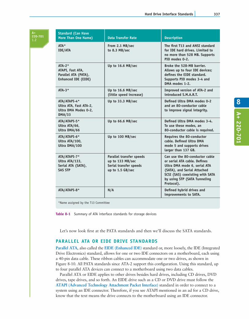
The ATA standards have undergone several revisions, which are summarized in Table 8-1.All but the last two standards apply only to PATA except for S.M.A.R.T., which is supportedby all SATA and PATA drives sold today. S.M.A.R.T. (Self-Monitoring Analysis andReporting Technology) is a system BIOS feature that monitors hard drive performance, diskspin up time, temperature, distance between the head and the disk, and other mechanicalactivities of the drive in order to predict when the drive is likely to fail. If S.M.A.R.T. suspectsa drive failure is about to happen, it displays a warning message. S.M.A.R.T. can be enabledand disabled in BIOS setup.
CHAPTER 8336 Supporting Hard Drives
Notes Remember from Chapter 7 that many memory standards exist because manufacturers andconsortiums are always trying to come up with faster and more reliable technologies. The many ATA standards exist for the same reasons. It’s unfortunate that you have to deal with so manytechnologies, but the old ones do stick around for many years after faster and better technologies are introduced.
A+220-7011.2
1986
Firs
t IDE d
rives
1994
ATA-1
1996
ATA-2
or E
IDE
1998
ATA-4
or A
TAPI-4
1997
ATA-3
2000
ATA-5
or A
TAPI-5
2002
ATA-6
or A
TAPI-6
2003
Inte
l ver
sion
of S
ATA-150
2005
ATA-7
and
T13 ve
rsion
of S
ATA-150
2006
ATA-8
1995
SCSI
2006
SATA-3
00
2009
SATA-6
00
SATA drives
Up to four EIDE or PATA drives (hard drives, CD drives and other drives)
Single IDE hard drive
SCSI drives
Figure 8-9 Timeline of interface standards used by internal drivesCourtesy: Course Technology/Cengage Learning
337Hard Drive Interface Standards
8
ATA* From 2.1 MB/sec The first T13 and ANSI standard IDE/ATA to 8.3 MB/sec for IDE hard drives. Limited to
no more than 528 MB. Supports PIO modes 0-2.
ATA-2* Up to 16.6 MB/sec Broke the 528-MB barrier. ATAPI, Fast ATA, Allows up to four IDE devices; Parallel ATA (PATA), defines the EIDE standard. Enhanced IDE (EIDE) Supports PIO modes 3-4 and
DMA modes 1-2.
ATA-3* Up to 16.6 MB/sec Improved version of ATA-2 and (little speed increase) introduced S.M.A.R.T.
ATA/ATAPI-4* Up to 33.3 MB/sec Defined Ultra DMA modes 0-2 Ultra ATA, Fast ATA-2, and an 80-conductor cable Ultra DMA Modes 0-2, to improve signal integrity.DMA/33
ATA/ATAPI-5* Up to 66.6 MB/sec Defined Ultra DMA modes 3-4. Ultra ATA/66, To use these modes, an Ultra DMA/66 80-conductor cable is required.
ATA/ATAPI-6* Up to 100 MB/sec Requires the 80-conductor Ultra ATA/100, cable. Defined Ultra DMA Ultra DMA/100 mode 5 and supports drives
larger than 137 GB.
ATA/ATAPI-7* Parallel transfer speeds Can use the 80-conductor cable Ultra ATA/133, up to 133 MB/sec or serial ATA cable. Defines Serial ATA (SATA), Serial transfer speeds Ultra DMA mode 6, serial ATA SAS STP up to 1.5 GB/sec (SATA), and Serial Attached
SCSI (SAS) coexisting with SATA by using STP (SATA Tunneling Protocol).
ATA/ATAPI-8* N/A Defined hybrid drives and improvements to SATA.
*Name assigned by the T13 Committee
Standard (Can Have More Than One Name) Data Transfer Rate Description
Table 8-1 Summary of ATA interface standards for storage devices
A+220-7011.2
A+ 220-701
Let’s now look first at the PATA standards and then we’ll discuss the SATA standards.
PARALLEL ATA OR EIDE DRIVE STANDARDSParallel ATA, also called the EIDE (Enhanced IDE) standard or, more loosely, the IDE (IntegratedDrive Electronics) standard, allows for one or two IDE connectors on a motherboard, each usinga 40-pin data cable. These ribbon cables can accommodate one or two drives, as shown inFigure 8-10. All PATA standards since ATA-2 support this configuration. Using this standard, upto four parallel ATA devices can connect to a motherboard using two data cables.
Parallel ATA or EIDE applies to other drives besides hard drives, including CD drives, DVDdrives, tape drives, and so forth. An EIDE drive such as a CD or DVD drive must follow theATAPI (Advanced Technology Attachment Packet Interface) standard in order to connect to asystem using an IDE connector. Therefore, if you see ATAPI mentioned in an ad for a CD drive,know that the text means the drive connects to the motherboard using an IDE connector.

CHAPTER 8338 Supporting Hard Drives
IDE connection onmotherboard
Connection for asecond drive
Power cord
Hard drive
IDE 40-pin data cable
Figure 8-10 A PC’s hard drive subsystem using parallel ATACourtesy: Course Technology/Cengage Learning
Notes Acronyms sometimes change over time. Years ago, technicians knew IDE to mean IntegratedDrive Electronics. As the term began to apply to other devices than hard drives, we renamed the acronymto become Integrated Device Electronics.
40-conductor cable
80-conductor cable
Red line down leftside indicates pin 1
Figure 8-11 In comparing the 80-conductor cable to the 40-conductor cable, note they are about the samewidth, but the 80-conductor cable has many more and finer wiresCourtesy: Course Technology/Cengage Learning
Other technologies and changes mentioned in Table 8-1 that you need to be aware of arethe two types of PATA data cables, DMA and PIO modes used by PATA, and IndependentDevice Timing. All these concerns are discussed next.
Two Types of PATA Ribbon CablesUnder parallel ATA, two types of ribbon cables are used. The older cable has 40 pins and40 wires. The 80-conductor IDE cable has 40 pins and 80 wires. Forty wires are used forcommunication and data, and an additional 40 ground wires reduce crosstalk on the cable. For maximum performance, an 80-conductor IDE cable is required by ATA/66 and above.Figure 8-11 shows a comparison between the two parallel cables. The 80-conductor cable is
A+220-7011.2

339Hard Drive Interface Standards
8
color-coded with the blue connector always connected to the motherboard. The connectors oneach cable otherwise look the same, and you can use an 80-conductor cable in place of a 40-conductor cable in a system.
The maximum recommended length of both cables is 18", although it is possible to pur-chase 24" cables. A ribbon cable usually comes bundled with a motherboard that has aPATA connector. Because ribbon cables can obstruct airflow inside a computer case, youcan purchase a smaller round PATA cable that is less obstructive to the airflow insidethe case.
DMA or PIO Transfer ModesA hard drive uses one of two methods to transfer data between the hard drive and memory:DMA (direct memory access) transfer mode or PIO (Programmed Input/Output) transfermode. DMA transfers data directly from the drive to memory without involving the CPU.PIO mode involves the CPU and is slower than DMA mode.
There are different modes for PIO and DMA, due to the fact that both standards haveevolved over the years. There are five PIO modes used by hard drives, from the slowest(PIO mode 0) to the fastest (PIO mode 4), and seven DMA modes from the slowest(DMA mode 0) to the fastest (DMA mode 6). All motherboards today support UltraDMA, which means that data is transferred twice for each clock beat, at the beginningand again at the end.
Most often, when installing a drive, the startup BIOS autodetects the drive and selects thefastest mode that the drive and the BIOS support. After installation, you can go into BIOSsetup and see which DMA mode is being used.
Independent Device TimingAs you saw in Table 8-1, there are different hard drive standards, each running at differentspeeds. If two hard drives share the same parallel ATA cable but use different standards,both drives will run at the speed of the slower drive unless the motherboard chipsetcontrolling the ATA connections supports a feature called Independent Device Timing. Mostchipsets today support this feature and with it, the two drives can run at different speeds aslong as the motherboard supports those speeds.
SERIAL ATA STANDARDSA consortium of manufacturers, called the Serial ATA International Organization (SATA-IO;see www.sata-io.org) and led by Intel, developed the serial ATA (SATA) standards. Thesestandards also have the oversight of the T13 Committee. SATA uses a serial data path ratherthan the traditional parallel data path. (Essentially, the difference between the two is thatdata is placed on a serial cable one bit following the next, but with parallel cabling, all datain a byte is placed on the cable at one time.) The three major revisions to SATA aresummarized in Table 8-2.
Serial ATA interfaces are much faster than PATA interfaces and are used by all types of drives, including hard drives, CD, DVD, Blu-ray, and tape drives. A motherboard can have two, four, six, or more SATA connectors, which are much easier to configure and use than PATA connectors. SATA supports hot-swapping, also called hot-plugging. With hot-swapping, you can connect and disconnect a drive while the system is running.
A SATA drive connects to one internal SATA connector on the motherboard by way ofa SATA data cable. An internal SATA data cable can be up to 1 meter in length, has 7pins, and is much narrower compared to the 40-pin parallel IDE cable (see Figure 8-12).The thin cables don’t hinder airflow inside a case as much as the wide parallel ATAcables do.
A+220-7011.2
A+ 220-701

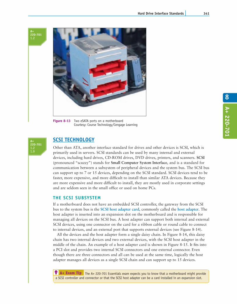
In addition to internal SATA connectors, the motherboard or an expansion card canprovide external SATA (eSATA) ports for external drives (see Figure 8-13). External SATA(eSATA) is up to six times faster than USB or FireWire. External SATA drives use a specialexternal shielded serial ATA cable up to 2 meters long.
When purchasing a SATA hard drive, keep in mind that the SATA standards for thedrive and the motherboard need to match. If either the drive or the motherboard use aslower SATA standard than the other device, the system will run at the slower speed.Other hard drive characteristics to consider when selecting a drive are covered later inthe chapter.
CHAPTER 8340 Supporting Hard Drives
Internal SATAdata cable
SATA connectoron motherboard
SATA hard drive
Figure 8-12 A SATA hard drive subsystem uses an internal SATA data cableCourtesy: Course Technology/Cengage Learning
A+220-7011.2 SATA Revision 1.x* 1.5 Gb/sec First introduced with ATA/ATAPI-7
SATA 1
Serial ATA-150
SATA/150
SATA-150
SATA Revision 2.x* 3 Gb/sec Currently, the most popular SATA standard
SATA 2
Serial ATA-300
SATA/300
SATA-300
SATA Revision 3.x* 6 Gb/sec Currently used only by SSD hard drives for laptopsSATA 3
Serial ATA-600
SATA/600
SATA-600
*Name assigned by the SATA-IO organization
SATA Standard Data Transfer Rate Comments
Table 8-2 SATA Standards
341Hard Drive Interface Standards
8
Figure 8-13 Two eSATA ports on a motherboardCourtesy: Course Technology/Cengage Learning
SCSI TECHNOLOGYOther than ATA, another interface standard for drives and other devices is SCSI, which isprimarily used in servers. SCSI standards can be used by many internal and external devices, including hard drives, CD-ROM drives, DVD drives, printers, and scanners. SCSI(pronounced “scuzzy”) stands for Small Computer System Interface, and is a standard forcommunication between a subsystem of peripheral devices and the system bus. The SCSI buscan support up to 7 or 15 devices, depending on the SCSI standard. SCSI devices tend to befaster, more expensive, and more difficult to install than similar ATA devices. Because theyare more expensive and more difficult to install, they are mostly used in corporate settingsand are seldom seen in the small office or used on home PCs.
THE SCSI SUBSYSTEMIf a motherboard does not have an embedded SCSI controller, the gateway from the SCSIbus to the system bus is the SCSI host adapter card, commonly called the host adapter. Thehost adapter is inserted into an expansion slot on the motherboard and is responsible formanaging all devices on the SCSI bus. A host adapter can support both internal and externalSCSI devices, using one connector on the card for a ribbon cable or round cable to connectto internal devices, and an external port that supports external devices (see Figure 8-14).
All the devices and the host adapter form a single daisy chain. In Figure 8-14, this daisychain has two internal devices and two external devices, with the SCSI host adapter in themiddle of the chain. An example of a host adapter card is shown in Figure 8-15. It fits intoa PCI slot and provides two internal SCSI connectors and one external connector. Eventhough there are three connectors and all can be used at the same time, logically the hostadapter manages all devices as a single SCSI chain and can support up to 15 devices.
A+220-7011.21.9
A+220-7011.2
A+ 220-701
A+ Exam Tip The A+ 220-701 Essentials exam expects you to know that a motherboard might providea SCSI controller and connector or that the SCSI host adapter can be a card installed in an expansion slot.

All devices go through the host adapter to communicate with the CPU or directly witheach other without involving the CPU. Each device on the bus is assigned a number from 0 to 15 called the SCSI ID, by means of DIP switches, dials on the device, or software set-tings. The host adapter is assigned SCSI ID 7, which has the highest priority over all otherdevices. The priority order is 7, 6, 5, 4, 3, 2, 1, 0, 15, 14, 13, 12, 11, 10, 9, and 8. Cablesconnect the devices physically in a daisy chain, sometimes called a straight chain. Thedevices can be either internal or external, and the host adapter can be at either end of thechain or somewhere in the middle. The SCSI ID identifies the physical device, which canhave several logical devices embedded in it. For example, a CD-ROM jukebox—a CD-ROMchanger with trays for multiple CDs—might have seven trays. Each tray is considered a logi-cal device and is assigned a Logical Unit Number (LUN) to identify it, such as 1 through 7or 0 through 6. The ID and LUN are written as two numbers separated by a colon. Forinstance, if the SCSI ID is 5, the fourth tray in the jukebox is device 5:4.
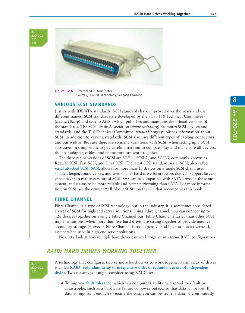
To reduce the amount of electrical “noise,” or interference, on a SCSI cable, each end ofthe SCSI chain has a terminating resistor. The terminating resistor can be a hardware deviceplugged into the last device on each end of the chain (see Figure 8-16), or the device canhave firmware-controlled termination resistance, which makes installation simpler.
CHAPTER 8342 Supporting Hard Drives
SCSI ribbon cable
Host adapterwith internaland externalconnections
SCSI hard drive
SCSI hard drive
Termination here
Two external SCSI devices
SCSIscanner
SCSICD-ROM
drive
Terminatorinstalled
SCSI cable
Figure 8-14 Using a SCSI bus, a SCSI host adapter card can support internal and external SCSI devicesCourtesy: Course Technology/Cengage Learning
Figure 8-15 PCI SCSI host adapter card by StarTechCourtesy of StarTech.com
A+220-7011.21.9
VARIOUS SCSI STANDARDSJust as with IDE/ATA standards, SCSI standards have improved over the years and usedifferent names. SCSI standards are developed by the SCSI T10 Technical Committee(www.t10.org) and sent to ANSI, which publishes and maintains the official versions of the standards. The SCSI Trade Association (www.scsita.org) promotes SCSI devices andstandards, and the T10 Technical Committee (www.t10.org) publishes information aboutSCSI. In addition to varying standards, SCSI also uses different types of cabling, connectors,and bus widths. Because there are so many variations with SCSI, when setting up a SCSIsubsystem, it’s important to pay careful attention to compatibility and make sure all devices,the host adapter, cables, and connectors can work together.
The three major versions of SCSI are SCSI-1, SCSI-2, and SCSI-3, commonly known asRegular SCSI, Fast SCSI, and Ultra SCSI. The latest SCSI standard, serial SCSI, also calledserial attached SCSI (SAS), allows for more than 15 devices on a single SCSI chain, usessmaller, longer, round cables, and uses smaller hard drive form factors that can support largercapacities than earlier versions of SCSI. SAS can be compatible with SATA drives in the samesystem, and claims to be more reliable and better performing than SATA. For more informa-tion on SCSI, see the content “All About SCSI” on the CD that accompanies this book.
FIBRE CHANNELFibre Channel is a type of SCSI technology, but in the industry, it is sometimes considered a rival of SCSI for high-end server solutions. Using Fibre Channel, you can connect up to126 devices together on a single Fibre Channel bus. Fibre Channel is faster than other SCSIimplementations, when more than five hard drives are strung together to provide massivesecondary storage. However, Fibre Channel is too expensive and has too much overhead,except when used in high-end server solutions.
Now let’s look at how multiple hard drives can work together in various RAID configurations.
RAID: HARD DRIVES WORKING TOGETHER
A technology that configures two or more hard drives to work together as an array of drivesis called RAID (redundant array of inexpensive disks or redundant array of independentdisks). Two reasons you might consider using RAID are:
To improve fault tolerance, which is a computer’s ability to respond to a fault orcatastrophe, such as a hardware failure or power outage, so that data is not lost. Ifdata is important enough to justify the cost, you can protect the data by continuously
343RAID: Hard Drives Working Together
8
A+220-7011.21.9
A+220-7011.2
Figure 8-16 External SCSI terminatorCourtesy: Course Technology/Cengage Learning
A+ 220-701
CHAPTER 8344 Supporting Hard Drives
writing two copies of it, each to a different hard drive. This method is most often usedon high-end, expensive file servers, but it is occasionally appropriate for a single-userworkstation.To improve performance by writing data to two or more hard drives so that a singledrive is not excessively used.
Several levels of RAID exist, but the three most commonly used are RAID 0, RAID 1, andRAID 5. Here is a brief description of each:
RAID 0 uses space from two or more physical disks to increase the disk spaceavailable for a single volume. RAID 0 writes to the physical disks evenly across alldisks so that no one disk receives all the activity, and therefore improves performance.Windows calls RAID 0 a striped volume. To understand that term, think of datastriped—or written across—several hard drives.RAID 1 is a type of drive imaging. It duplicates data on one drive to another drive andis used for fault tolerance. (A drive image is a duplication of everything written to ahard drive.) Each drive has its own volume, and the two volumes are called mirrors. If one drive fails, the other continues to operate and data is not lost. A variation ofmirroring is disk duplexing, which uses two hard drive controllers, one for each drive.If one controller fails, the other controller keeps on working, providing more assuranceof fault tolerance than mirroring. Windows calls RAID 1 a mirrored volume.RAID 5 stripes data across three or more drives and uses parity checking, so that ifone drive fails, the other drives can re-create the data stored on the failed drive. Datais not duplicated, and, therefore, RAID 5 makes better use of volume capacity. RAID 5 drives increase performance and provide fault tolerance. Windows calls thesedrives RAID-5 volumes.
Besides the three levels of RAID listed, another practice of tying two drives together in anarray is called spanning. With spanning, two hard drives are configured as a single volume.Data is written to the first drive, and when it is full, the data continues to be written to thesecond drive. The advantage of spanning is that you can have a very large file that is larger thaneither drive. The disadvantages of spanning are that it does not provide fault tolerance, and thatit does not improve performance. Sometimes spanning is called JBOD (Just a Bunch of Disks).
All RAID configurations can be accomplished at the hardware level or the operatingsystem level. Configuring RAID at the hardware level is considered best practice because, if Windows gets corrupted, the hardware might still be able to protect the data. Also,hardware RAID is generally faster than operating system RAID. You will learn how toimplement hardware RAID later in the chapter. Windows RAID is covered in Chapter 13.
ABOUT FLOPPY DRIVES
Even though a floppy disk drive (FDD) holds only 1.44 MB of data, these drives are stillused in some computers today, and you need to know how to support them. Floppy drivescan be especially useful when recovering from a failed BIOS update. Also, floppy disks areinexpensive and easy for transferring small amounts of data. In this part of the chapter,you’ll learn about the hardware and file system used by floppy drives.
A+ Exam Tip The A+ 220-701 Essentials exam expects you to be able to contrast RAID 0, RAID 1,and RAID 5.
A+220-7011.2
A+220-7011.1

345About Floppy Drives
8
A+ 220-701
FLOPPY DRIVE HARDWAREYears ago, floppy drives came in two sizes to accommodate either a 51⁄4" or 31⁄2" floppy disk.The 31⁄2" disks were formatted as high density (1.44 MB), extra-high density (2.88 MB), anddouble density (720 K). The only floppy drives you see in use today are the 31⁄2" high-densitydrives that hold 1.44 MB of data.
Figure 8-17 shows the floppy drive subsystem, which consists of the floppy drive, its ribboncable, power cable, and connections. The ribbon data cable connects to a 34-pin floppy driveconnector on the motherboard. Recall that most hard drives use the larger Molex connectoras a power connector, but floppy drives use the smaller Berg connector. The Berg powerconnector has a small plastic latch that snaps in place when you connect it to the drive.
Today’s floppy drive cables have a connector at each end and accommodate a single drive,but older cables, like the one in Figure 8-17, have an extra connector or two in the middle ofthe cable for a second floppy drive. For these systems, you can install two floppy drives onthe same cable, and the drives will be identified by BIOS as drive A and drive B. Figure 8-18shows an older floppy drive cable. Notice in the figure the twist in the cable. The drive thathas the twist between it and the controller is drive A. The drive that does not have the twistbetween it and the controller is drive B. Also notice in the figure the edge color down oneside of the cable, which identifies the pin-1 side of the 34-pin connector.
Power cord
Berg connector
Data cableconnects tomotherboard
Floppy drive
34-pindata cable
Figure 8-17 Floppy drive subsystem: floppy drive, 34-pin data cable, and power connectorCourtesy: Course Technology/Cengage Learning
A+220-7011.1
Twist in cable
Drive B connections(two styles)
Drive A connector
Connects to motherboardor older controller card
Edge color on cableindicates the pin-1side of cable
Figure 8-18 Twist in cable determines which drive is drive ACourtesy: Course Technology/Cengage Learning

CHAPTER 8346 Supporting Hard Drives
A+ Exam Tip The A+ 220-701 Essentials exam expects you to be familiar with a floppy disk drive (FDD).
FLOPPY DRIVE FILE SYSTEMLearning about the details of a floppy drive file system can help you understand how a harddrive is organized. The floppy drive file system is similar to that of a hard drive file system,yet it is simpler and easier to understand.
When floppy disks are first manufactured, the disks have nothing on them; they are blanksheets of magnetically coated plastic. During the formatting process, tracks and sectors tohold the data are written to the blank surface (see Figure 8-19).
There are 80 tracks, or circles, on the top side of the disk and 80 more tracks on the bottom.The tracks are numbered 0 through 79. Each track has 18 sectors, numbered 1 through 18 for atotal of 1440 sectors on each side. Because each sector holds 512 bytes of data, a 31⁄2", high-densityfloppy disk has 2880 x 512 = 1,474,560 bytes of data. Divide this number by 1024 to convertbytes to kilobytes and you will find out that the storage capacity of this disk is 1440 kilobytes.You can then divide 1440 by 1000 to convert kilobytes to megabytes, and the storage is 1.44 MB.
1
TrackSide 0Track 0Sector 1
2
8
3
7
4
6
5
91011
12
13
14
15
16
1718
Figure 8-19 31⁄2", high-density floppy disk showing tracks and sectorsCourtesy: Course Technology/Cengage Learning
Notes There is a discrepancy in the way the computer industry defines a megabyte. Sometimes1 megabyte = 1,000 kilobytes; at other times, we use the relationship 1 megabyte = 1,024 kilobytes.Computers calculate in powers of 2, and 1,024 is 2 raised to the 10th power.
A+220-7011.1
Most floppy disks come already formatted, but occasionally you will need to format one.Whether you use the format command at a command prompt or Windows Explorer toformat a floppy disk, the following are created:
Tracks and sectors. These tracks and sectors provide the structure to hold data on the disk.The boot record. The first sector on the disk, called the boot sector or boot record,contains the information about how the disk is organized and the file system used.
347How to Select and Install Hard Drives and Floppy Drives
8
Two copies of the file allocation table (FAT). Under Windows, a hard drive can useeither the NTFS or FAT32 file system, but a floppy drive is always formatted using theFAT12 file system. Using FAT12, each entry in the file allocation table (FAT) is 12 bits.Each FAT entry lists how each cluster (or file allocation unit) on the disk is currentlyused. Using FAT12, one sector equals one cluster, so every sector or cluster on the diskis accounted for in the FAT. A file is stored in one or more clusters that do not have tobe contiguous on the disk.The root directory. The root directory contains a fixed number of rows to accommo-date a predetermined number of files and subdirectories. A 31⁄2", high-density floppydisk has 224 entries in the root directory. Some important items in a directory are alist of filenames and their extensions, the time and date of creation or last update ofeach file, and the file attributes. Attributes are on/off switches indicating the archive,system file, hidden file, and read-only file status of the file or directory.
The root directory and all subdirectories contain the same information about each file.Only the root directory has a limitation on the number of entries because it has a fixedlength that it uses to store all filenames and folder names created in the root directory.Subdirectories can have as many entries as disk space allows. Because long filenames requiremore room in a directory than short filenames, assigning long filenames reduces the numberof files that can be stored in the root directory.
Let’s now turn our attention back to hard drives and focus on what you need to knowwhen selecting one.
Notes For tech-hungry readers, you can use the DEBUG command to view the contents of the bootrecord or FAT. How to do that is covered in the “Behind the Scenes with DEBUG” content that you canfind on the CD that accompanies this book. Also, to see a group of tables showing the contents of thefloppy disk boot record, the root directory, and the meaning of each bit in the attribute byte, see thecontent on the CD titled “FAT Details.”
A+ Exam Tip The content on the A+ 220-701 Essentials exam ends here and the content on theA+ 220-702 Practical Application exam begins.
HOW TO SELECT AND INSTALL HARD DRIVES AND FLOPPY DRIVES
In this part of the chapter, you’ll learn how to select a hard drive for your system. Then, you’lllearn the details of installing a serial ATA drive and a parallel ATA drive in a system. Next,you’ll learn how to deal with the problem of installing a hard drive in a bay that is too widefor it and also how to set up a RAID system. Lastly, you’ll see how to install a floppy drive.
SELECTING A HARD DRIVEWhen selecting a hard drive, keep in mind that there are many hard drive standards. To get thebest performance from the system, the system BIOS on the motherboard or the firmware on thehard drive controller card must use the same standards used by the drive. If the motherboard
A+220-7011.1
A+220-7021.1
A+ 220-702

CHAPTER 8348 Supporting Hard Drives
or controller card does not use the same standards as the hard drive, they will probably revertto a slower standard that both can use, or the drive will not work at all. There’s no point inbuying an expensive hard drive with features that your system cannot support.
Therefore, when making purchasing decisions, you need to know what standards the motherboard or controller card uses. To find out, see the documentation for the board or thecard. For the motherboard, you can look at BIOS setup screens to see which standards arementioned. However, know that when installing a drive, you don’t need to know which ATAstandard a hard drive supports, because the startup BIOS uses autodetection. With autodetection,the BIOS detects the new drive and automatically selects the correct drive capacity and configura-tion, including the best possible standard supported by both the hard drive and the motherboard.
One more point is important to know: Legacy motherboards or hard drives might presentcomplex situations. If you install a new drive that the startup BIOS of a legacy motherboardis not designed to support, the BIOS will either not recognize the drive at all or will detect thedrive and report in BIOS setup that the drive has a smaller capacity than it actually does. Thesolution is to flash BIOS, replace the controller card, or replace the motherboard. For a fulldiscussion of how to deal with legacy motherboards or drives, see the content “Selecting andInstalling Hard Drives using Legacy Motherboards” on the CD that accompanies this book.
When purchasing a hard drive, consider the following factors that affect performance,use, and price:
The capacity of the drive. Today’s hard drives for desktop systems are in the range of80 GB to more than 1.5 TB. The more gigabytes or terabytes, the higher the price.The spindle speed. Hard drives for desktop systems run at 5400, 7200, or 10,000RPM (revolutions per minute). The most common is 7200 RPM. The higher theRPMs, the faster the drive.The interface standard. Use the standards your motherboard supports. For SATA,most likely that will be SATA-300. For a PATA IDE drive, most likely that will beUltra ATA-100. For external drives, common standards are eSATA, FireWire 800 or400, and Hi-Speed USB.The cache or buffer size. Buffers improve hard drive performance and can range in sizefrom 2 MB to 32 MB. The more the better, though the cost goes up as the size increases.The average seek time (time to fetch data). Look for 13 to 8.5 ms (milliseconds). Thelower the number, the higher the drive performance and cost.Hybrid drive. A hybrid drive costs more, but performs better than other comparabledesktop drives. Solid state drives are currently only available for laptops.
When selecting a drive, consider the manufacturer warranty and be sure to match thedrive to what your motherboard supports. Also, be sure to keep the receipt with thewarranty statement. After you know what drive your system can support, you then canselect a drive that is appropriate for the price range and intended use of your system. Forexample, Seagate has two lines of IDE hard drives: The Barracuda is less expensive andintended for the desktop market, and the Cheetah is more expensive and targets the servermarket. When purchasing a drive, you can compare price and features by searching retailsites or the Web sites of the drive manufacturers. Some of the more popular ones are listedin Table 8-3. The same manufacturers usually produce ATA drives and SCSI drives.
Now let’s turn our attention to the step-by-step process of installing a Serial ATA drive.
STEPS TO INSTALL A SERIAL ATA DRIVEA motherboard that has serial ATA connectors most likely has one or more PATA connec-tors, too. A PATA connector can be used for an optical drive or some other EIDE drive
A+220-7021.1
349How to Select and Install Hard Drives and Floppy Drives
8
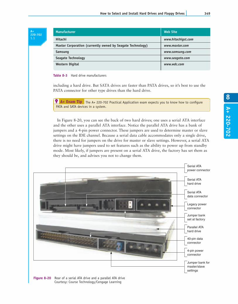
including a hard drive. But SATA drives are faster than PATA drives, so it’s best to use thePATA connector for other type drives than the hard drive.
In Figure 8-20, you can see the back of two hard drives; one uses a serial ATA interfaceand the other uses a parallel ATA interface. Notice the parallel ATA drive has a bank ofjumpers and a 4-pin power connector. These jumpers are used to determine master or slavesettings on the IDE channel. Because a serial data cable accommodates only a single drive,there is no need for jumpers on the drive for master or slave settings. However, a serial ATAdrive might have jumpers used to set features such as the ability to power up from standbymode. Most likely, if jumpers are present on a serial ATA drive, the factory has set them asthey should be, and advises you not to change them.
Hitachi www.hitachigst.com
Maxtor Corporation (currently owned by Seagate Technology) www.maxtor.com
Samsung www.samsung.com
Seagate Technology www.seagate.com
Western Digital www.wdc.com
Manufacturer Web Site
Table 8-3 Hard drive manufacturers
A+ Exam Tip The A+ 220-702 Practical Application exam expects you to know how to configurePATA and SATA devices in a system.
A+220-7021.1
A+ 220-702
4-pin powerconnector
40-pin dataconnector
Parallel ATAhard drive
Jumper bank formaster/slavesettings
Jumper bankset at factory
Serial ATAdata connector
Legacy powerconnector
Serial ATAhard drive
Serial ATApower connector
Figure 8-20 Rear of a serial ATA drive and a parallel ATA driveCourtesy: Course Technology/Cengage Learning

CHAPTER 8350 Supporting Hard Drives
SATA to PATAconverter
A
B
PATA to SATA converter
Figure 8-21 SATA to PATA and PATA to SATA convertersCourtesy: Course Technology/Cengage Learning
A+220-7021.1
Some serial ATA drives have two power connectors, as does the one in Figure 8-20.Choose between the serial ATA power connector (which is the preferred connector) or thelegacy 4-pin connector, but never install two power cords to the drive at the same time,because this could damage the drive.
If you have a PATA drive and a SATA connector on the motherboard, or you have a SATAdrive and a PATA connector on the motherboard, you can purchase an adapter to make the harddrive connector fit your motherboard connector. Figure 8-21 shows two converters: one convertsSATA drives to PATA motherboards and the other converts PATA drives to SATA motherboards.When you use a converter, know that the drive will run at the slower PATA speed.
You can also purchase a SATA and/or PATA controller card that can provide internalPATA or SATA connectors and external eSATA connectors. You might want to use a controller card when (1) the motherboard drive connectors are not functioning; or (2) themotherboard does not support an ATA standard you want to implement (such as a SATA IIdrive). Figure 8-22 shows a storage controller card that offers one Ultra ATA-133/IDE connection, two internal SATA I connections, and one eSATA port.
Now let’s look at the step-by-step process of installing a SATA drive.
STEP 1: PREPARE FOR THE INSTALLATIONPrepare for the installation by knowing your starting point, reading the documentation, andpreparing your work area.
Know Your Starting PointAs with installing any other devices, before you begin installing your hard drive, make sureyou know where your starting point is. Do this by answering these questions: How is your

351How to Select and Install Hard Drives and Floppy Drives
8
A+220-7021.1
A+ 220-702
system configured? Is everything working properly? Verify which of your system’s devicesare working before installing a new one. Later, if a device does not work, the informationwill help you isolate the problem. Keeping notes is a good idea whenever you install newhardware or software or make any other changes to your PC system. Write down what youknow about the system that might be important later.
As always, just in case you lose BIOS setup information in the process, write downany variations in setup from the default settings. Two good places to record BIOS settings are the notebook you keep about this computer and the manual for the motherboard.
Read DocumentationBefore you take anything apart, carefully read all the documentation for the drive andcontroller card, as well as the part of your motherboard documentation that covers harddrive installation. Make sure that you can visualize all the steps in the installation. If youhave any questions, keep researching until you locate the answer. You can also call techni-cal support, or ask a knowledgeable friend for help. As you get your questions answered,you might discover that what you are installing will not work on your computer, but thatis better than coping with hours of frustration and a disabled computer. You cannotalways anticipate every problem, but at least you can know that you made your besteffort to understand everything in advance. What you learn in thorough preparation paysoff every time!
IDE connector
Two SATAconnectors
eSATA port
Figure 8-22 EIDE and SATA storage controller cardCourtesy: Course Technology/Cengage Learning
Notes When installing hardware and software, don’t install too many things at once. If somethinggoes wrong, you won’t know what’s causing the problem. Install one device, start the system, and confirm that the new device is working before installing another.

CHAPTER 8352 Supporting Hard Drives
A+220-7021.1
Notes If there are not enough power cords from a power supply, you can purchase a Y connectorthat can add an additional power cord.
Prepare Your Work Area and Take PrecautionsThe next step is to prepare a large, well-lit place to work. Set out your tools, documenta-tion, new hardware, and notebook. Remember the basic rules concerning static electricity,which you learned in Chapter 4. Be sure to protect against ESD by wearing a groundbracelet during the installation. You need to also avoid working on carpet in the winterwhen there’s a lot of static electricity.
Some added precautions for working with a hard drive are as follows:
Handle the drive carefully.Do not touch any exposed circuitry or chips.Prevent other people from touching exposed microchips on the drive.When you first take the drive out of the static-protective package, touch the packagecontaining the drive to a screw holding an expansion card or cover, or to a metal partof the computer case, for at least two seconds. This drains the static electricity fromthe package and from your body.If you must set down the drive outside the static-protective package, place itcomponent-side-up on a flat surface.Do not place the drive on the computer case cover or on a metal table.
If you’re assembling a new system, it’s best to install drives before you install the motherboard so that you will not accidentally bump sensitive motherboard componentswith the drives.
STEP 2: INSTALL THE DRIVESo now you’re ready to get started. Follow these steps to install the drive in the case:
1. Turn off the computer and unplug it. Press the power button to drain the power.Remove the computer case cover. Check that you have an available power cord fromthe power supply for the drive.
2. Decide which bay will hold the drive. To do that, examine the locations of the drivebays and the length of the data cables and power cords. Bays designed for harddrives do not have access to the outside of the case, unlike bays for optical drives and other drives in which disks are inserted. Also, some bays are wider than others to accommodate wide drives such as CD drives and DVD drives. Will the data cablereach the drives and the motherboard connector? If not, rearrange your plan forlocating the drives in the bays, or purchase a custom-length data cable. Some baysare stationary, meaning the drive is installed inside the bay as it stays in the case.Other bays are removable; you remove the bay and install the drive in the bay, andthen return the bay to the case.
3. For a stationary bay, slide the drive in the bay, and secure one side of the drive withone or two short screws (see Figure 8-23). It’s best to use two screws so the drive willnot move in the bay, but sometimes a bay only provides a place for a single screw oneach side.

353How to Select and Install Hard Drives and Floppy Drives
8
A+220-7021.1
A+ 220-702
4. Carefully, without disturbing the drive, turn the case over and put one or two screwson the other side of the drive (see Figure 8-24).
Figure 8-23 Secure one side of the drive with one or two screwsCourtesy: Course Technology/Cengage Learning
Caution
Hard drive
Figure 8-24 Secure the other side of the drive with one or two screwsCourtesy: Course Technology/Cengage Learning
Notes Do not allow torque to stress the drive. In other words, don’t force a drive into a space thatis too small for it. Also, placing two screws in diagonal positions across the drive can place pressurediagonally on the drive.
5. Check the motherboard documentation to find out which serial ATA connectors on theboard to use first. For example, four serial ATA connectors are shown in Figure 8-25.The documentation says to use the two red connectors (labeled SATA1 and SATA2 onthe board) before you use the black connectors (labeled SATA3 and SATA4). Connect
Be sure the screws are not too long. If they are, you can screw too far into the drivehousing, which will damage the drive itself.
CHAPTER 8354 Supporting Hard Drives
A+220-7021.1
Figure 8-25 This motherboard has four serial ATA connectorsCourtesy: Course Technology/Cengage Learning
Figure 8-26 Connect the SATA power cord to the driveCourtesy: Course Technology/Cengage Learning
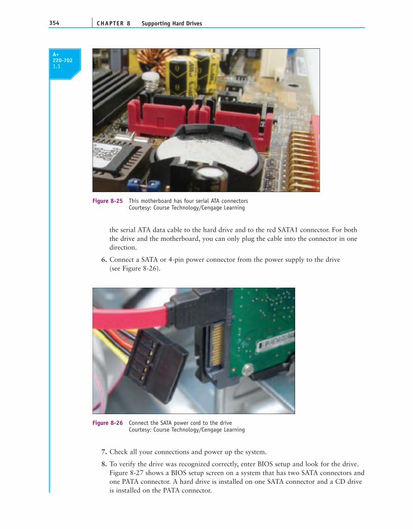
the serial ATA data cable to the hard drive and to the red SATA1 connector. For boththe drive and the motherboard, you can only plug the cable into the connector in onedirection.
6. Connect a SATA or 4-pin power connector from the power supply to the drive (see Figure 8-26).
7. Check all your connections and power up the system.
8. To verify the drive was recognized correctly, enter BIOS setup and look for the drive. Figure 8-27 shows a BIOS setup screen on a system that has two SATA connectors andone PATA connector. A hard drive is installed on one SATA connector and a CD driveis installed on the PATA connector.

355How to Select and Install Hard Drives and Floppy Drives
8
A+220-7021.1
Figure 8-27 BIOS setup screen showing a SATA hard drive and PATA CD drive installedCourtesy: Course Technology/Cengage Learning
Notes If the drive light on the front panel of the computer case does not work after you install anew drive, try reversing the LED wire on the motherboard pins.
STEP 3: USE WINDOWS TO PARTITION AND FORMAT THE NEW DRIVEIf you are installing a new hard drive in a system that is to be used for a new Windowsinstallation, after you have physically installed the drive, boot from the Windows setup CDor DVD, and follow the directions on the screen to install Windows on the new drive. The setup process partitions and formats the new drive before it begins the Windowsinstallation. How to install Windows is covered in Chapter 12.
If you are installing a second hard drive in a system that already has Windows installedon the first hard drive, use Windows to partition and format the second drive. Follow these steps:
1. Boot the system to the Windows Vista desktop.
2. Click Start, right-click Computer (for Windows XP, right-click My Computer), andselect Manage from the shortcut menu. Respond to the UAC box. In the ComputerManagement window, click Disk Management. The Disk Management window opens(see Figure 8-28).
3. In Figure 8-28, the new hard drive shows as Disk 1. Right-click Disk 1 and selectInitialize Disk from the shortcut menu, as shown in the figure.
4. On the next screen (see Figure 8-29), select MBR (Master Boot Record) and click OK.The drive will be initialized as a Basic Disk.
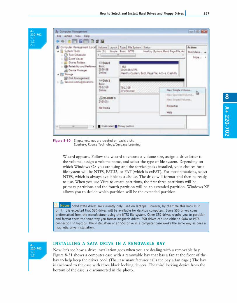
5. To format the drive, right-click the unallocated space on the drive and select NewSimple Volume from the shortcut menu (see Figure 8-30). The New Simple Volume
A+220-7021.11.2 2.3
A+ 220-702

CHAPTER 8356 Supporting Hard Drives
Figure 8-28 Use Disk Management to partition the new drive Courtesy: Course Technology/Cengage Learning
Figure 8-29 Select MBR as the partition style for the new driveCourtesy: Course Technology/Cengage Learning
A+220-7021.11.2 2.3
357How to Select and Install Hard Drives and Floppy Drives
8
Figure 8-30 Simple volumes are created on basic disksCourtesy: Course Technology/Cengage Learning
A+220-7021.11.2 2.3
A+ 220-702
Notes Solid state drives are currently only used on laptops. However, by the time this book is inprint, it is expected that SSD drives will be available for desktop computers. Some SSD drives comepreformatted from the manufacturer using the NTFS file system. Other SSD drives require you to partitionand format them the same way you format magnetic drives. SSD drives can use either a SATA or PATAconnection in laptops. The installation of an SSD drive in a computer case works the same way as does amagnetic drive installation.
Wizard appears. Follow the wizard to choose a volume size, assign a drive letter to the volume, assign a volume name, and select the type of file system. Depending onwhich Windows OS you are using and the service packs installed, your choices for afile system will be NTFS, FAT32, or FAT (which is exFAT). For most situations, selectNTFS, which is always available as a choice. The drive will format and then be readyto use. When you use Vista to create partitions, the first three partitions will beprimary partitions and the fourth partition will be an extended partition. Windows XPallows you to decide which partition will be the extended partition.
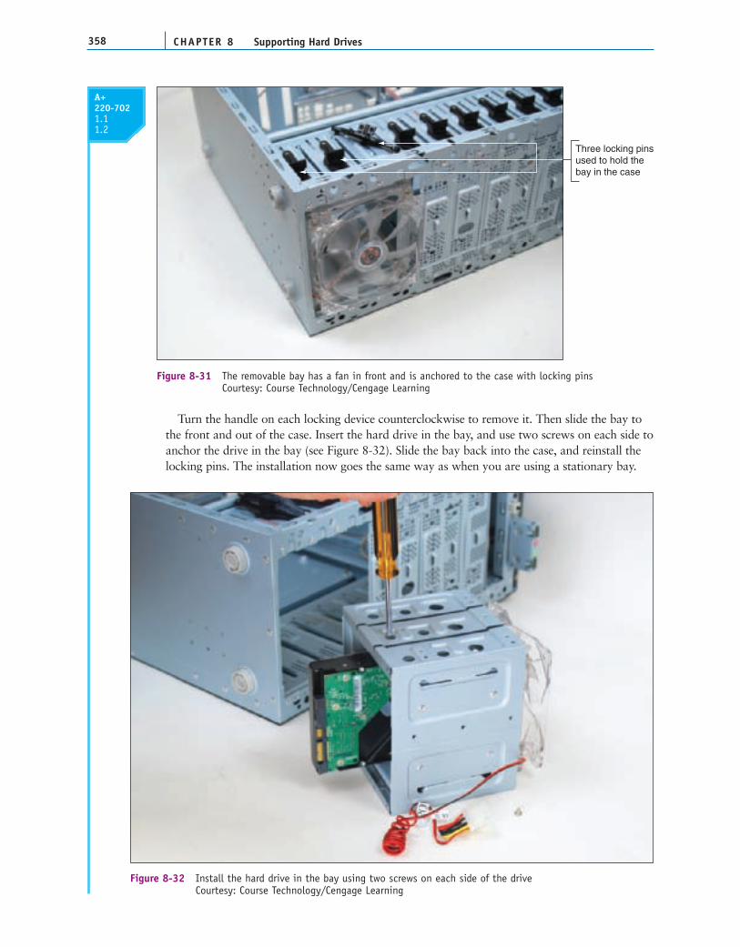
INSTALLING A SATA DRIVE IN A REMOVABLE BAYNow let’s see how a drive installation goes when you are dealing with a removable bay.Figure 8-31 shows a computer case with a removable bay that has a fan at the front of thebay to help keep the drives cool. (The case manufacturer calls the bay a fan cage.) The bayis anchored to the case with three black locking devices. The third locking device from thebottom of the case is disconnected in the photo.
A+220-7021.11.2
CHAPTER 8358 Supporting Hard Drives
A+220-7021.11.2
Turn the handle on each locking device counterclockwise to remove it. Then slide the bay tothe front and out of the case. Insert the hard drive in the bay, and use two screws on each side toanchor the drive in the bay (see Figure 8-32). Slide the bay back into the case, and reinstall thelocking pins. The installation now goes the same way as when you are using a stationary bay.
Three locking pinsused to hold thebay in the case
Figure 8-31 The removable bay has a fan in front and is anchored to the case with locking pinsCourtesy: Course Technology/Cengage Learning
Figure 8-32 Install the hard drive in the bay using two screws on each side of the driveCourtesy: Course Technology/Cengage Learning

359How to Select and Install Hard Drives and Floppy Drives
8
A+ 220-702
A+220-7021.11.2
STEPS TO CONFIGURE AND INSTALL A PARALLEL ATA DRIVEFollowing the PATA or EIDE standard, a motherboard can support up to four EIDE devicesusing either 80-conductor or 40-conductor cables. The motherboard offers two IDE connec-tors (see Figure 8-33). Each connector accommodates one IDE channel, and each channelcan accommodate one or two IDE devices. One channel is called the primary channel, whilethe other channel is called the secondary channel. Each IDE connector uses one 40-pincable. The cable has two connectors on it: one connector in the middle of the cable and oneat the far end. An EIDE device can be a hard drive, DVD drive, CD drive, tape drive, oranother type of drive. One device is configured to act as the master controlling the channel,and the other device on the channel is the slave. There are, therefore, four possible configu-rations for four EIDE devices in a system:
Primary IDE channel, master devicePrimary IDE channel, slave deviceSecondary IDE channel, master deviceSecondary IDE channel, slave device
The master or slave designations are made by setting jumpers or DIP switches on thedevices, or by using a special cable-select data cable. Documentation can be tricky. Somehard drive documentation labels the master drive setting as the Drive 0 setting and theslave drive setting as the Drive 1 setting rather than using the terms master and slave. Theconnectors on a parallel ATA 80-conductor cable are color-coded (see Figure 8-34). Usethe blue end to connect to the motherboard; use the black end to connect to the drive.
Motherboard
IDE cables
Connectors for masterand slave drives
Two IDE channels, primary and secondary
Connectors for masterand slave drives
Figure 8-33 A motherboard supporting PATA has two IDE channels; each can support a master and slavedrive using a single EIDE cableCourtesy: Course Technology/Cengage Learning
Gray connectorfor second drive
Black connectorfor first drive
Blue connectorto motherboard
Figure 8-34 80-conductor cable connectors are color-codedCourtesy: Course Technology/Cengage Learning
CHAPTER 8360 Supporting Hard Drives
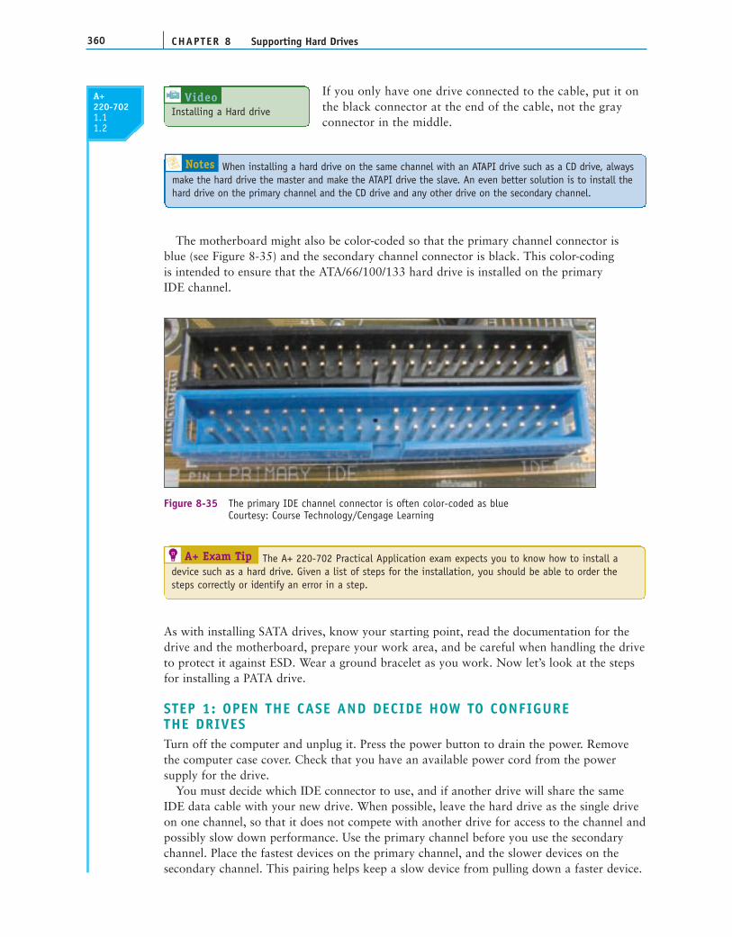
If you only have one drive connected to the cable, put it onthe black connector at the end of the cable, not the grayconnector in the middle.
The motherboard might also be color-coded so that the primary channel connector is blue (see Figure 8-35) and the secondary channel connector is black. This color-coding is intended to ensure that the ATA/66/100/133 hard drive is installed on the primary IDE channel.
A+220-7021.11.2
Notes When installing a hard drive on the same channel with an ATAPI drive such as a CD drive, alwaysmake the hard drive the master and make the ATAPI drive the slave. An even better solution is to install thehard drive on the primary channel and the CD drive and any other drive on the secondary channel.
Installing a Hard driveVideo
Figure 8-35 The primary IDE channel connector is often color-coded as blueCourtesy: Course Technology/Cengage Learning
A+ Exam Tip The A+ 220-702 Practical Application exam expects you to know how to install adevice such as a hard drive. Given a list of steps for the installation, you should be able to order thesteps correctly or identify an error in a step.
As with installing SATA drives, know your starting point, read the documentation for thedrive and the motherboard, prepare your work area, and be careful when handling the driveto protect it against ESD. Wear a ground bracelet as you work. Now let’s look at the stepsfor installing a PATA drive.
STEP 1: OPEN THE CASE AND DECIDE HOW TO CONFIGURE THE DRIVESTurn off the computer and unplug it. Press the power button to drain the power. Removethe computer case cover. Check that you have an available power cord from the powersupply for the drive.
You must decide which IDE connector to use, and if another drive will share the sameIDE data cable with your new drive. When possible, leave the hard drive as the single driveon one channel, so that it does not compete with another drive for access to the channel andpossibly slow down performance. Use the primary channel before you use the secondarychannel. Place the fastest devices on the primary channel, and the slower devices on thesecondary channel. This pairing helps keep a slow device from pulling down a faster device.

361How to Select and Install Hard Drives and Floppy Drives
8
A+ 220-702
A+220-7021.11.2
As an example of this type of pairing, suppose you have a tape drive, CD drive, and twohard drives. Because the two hard drives are faster than the tape drive and CD drive, put thetwo hard drives on one channel and the tape drive and CD drive on the other.
STEP 2: SET THE JUMPERS ON THE DRIVEOften, diagrams of the jumper settings are printed on the top of the hard drive housing (see Figure 8-36). If they are not, see the documentation, or visit the Web site of the drivemanufacturer. (Hands-On Project 8-4 gives you practice researching jumper settings.)
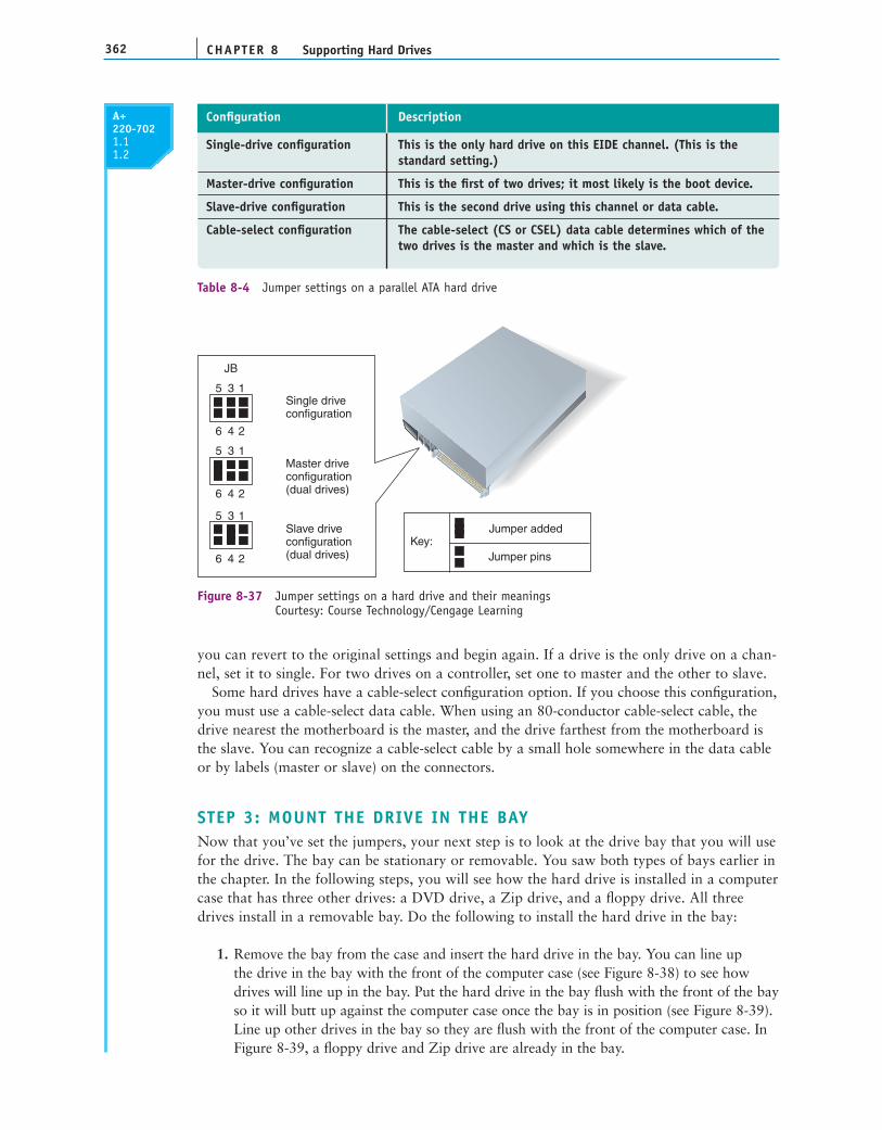
Table 8-4 lists the four choices for jumper settings, and Figure 8-37 shows a typicaljumper arrangement for a drive that uses three of these settings. In Figures 8-36 and 8-37,note that a black square represents an empty pin and a black rectangle represents a pair ofpins with a jumper in place. Know that your hard drive might not have the first configura-tion as an option, but it should have a way of indicating if the drive will be the masterdevice. The factory default setting is usually correct for the drive to be the single drive on asystem. Before you change any settings, write down the original ones. If things go wrong,
Notes If you have three or fewer devices, allow the fastest hard drive to be your boot device andthe only device on the primary channel.
Sla
veM
aste
rS
ingl
e
Standard settings
Power40-pinconn.
9 7 5 3 1
10 8 6 4 2
J8 Jumper settings
Most drives are shipped with ajumper as shown above in a parkedposition; there is no need to remove
Figure 8-36 A PATA drive most likely will have diagrams of jumper settings for master and slave optionsprinted on the drive housingCourtesy: Course Technology/Cengage Learning
CHAPTER 8362 Supporting Hard Drives
A+220-7021.11.2
you can revert to the original settings and begin again. If a drive is the only drive on a chan-nel, set it to single. For two drives on a controller, set one to master and the other to slave.
Some hard drives have a cable-select configuration option. If you choose this configuration,you must use a cable-select data cable. When using an 80-conductor cable-select cable, thedrive nearest the motherboard is the master, and the drive farthest from the motherboard isthe slave. You can recognize a cable-select cable by a small hole somewhere in the data cableor by labels (master or slave) on the connectors.
STEP 3: MOUNT THE DRIVE IN THE BAYNow that you’ve set the jumpers, your next step is to look at the drive bay that you will usefor the drive. The bay can be stationary or removable. You saw both types of bays earlier inthe chapter. In the following steps, you will see how the hard drive is installed in a computercase that has three other drives: a DVD drive, a Zip drive, and a floppy drive. All threedrives install in a removable bay. Do the following to install the hard drive in the bay:
1. Remove the bay from the case and insert the hard drive in the bay. You can line up the drive in the bay with the front of the computer case (see Figure 8-38) to see howdrives will line up in the bay. Put the hard drive in the bay flush with the front of the bayso it will butt up against the computer case once the bay is in position (see Figure 8-39).Line up other drives in the bay so they are flush with the front of the computer case. InFigure 8-39, a floppy drive and Zip drive are already in the bay.
Single-drive configuration This is the only hard drive on this EIDE channel. (This is the standard setting.)
Master-drive configuration This is the first of two drives; it most likely is the boot device.
Slave-drive configuration This is the second drive using this channel or data cable.
Cable-select configuration The cable-select (CS or CSEL) data cable determines which of thetwo drives is the master and which is the slave.
Configuration Description
Table 8-4 Jumper settings on a parallel ATA hard drive
1
2
Single driveconfiguration
Master driveconfiguration(dual drives)
Slave driveconfiguration(dual drives)
Key:Jumper added
Jumper pins
JB
5
6
3
4
1
2
5
6
3
4
1
2
5
6
3
4
Figure 8-37 Jumper settings on a hard drive and their meaningsCourtesy: Course Technology/Cengage Learning

363How to Select and Install Hard Drives and Floppy Drives
8
A+ 220-702
A+220-7021.11.2
2. You must be able to securely mount the drive in the bay; the drive should not movewhen it is screwed down. Line up the drive and bay screw holes, and make sure every-thing will fit. After checking the position of the drive and determining how screws areplaced, install four screws (two on each side) to mount the drive in the bay.
3. Decide whether to connect the data cable to the drive before or after you insert thebay inside the computer case, depending on how accessible the connections are. In this
Figure 8-38 Line up the floppy drive in the removable bay so it’s flush with the front of the caseCourtesy: Course Technology/Cengage Learning
Figure 8-39 Position the hard drive flush with the end of the bayCourtesy: Course Technology/Cengage Learning
CHAPTER 8364 Supporting Hard Drives
A+220-7021.11.2
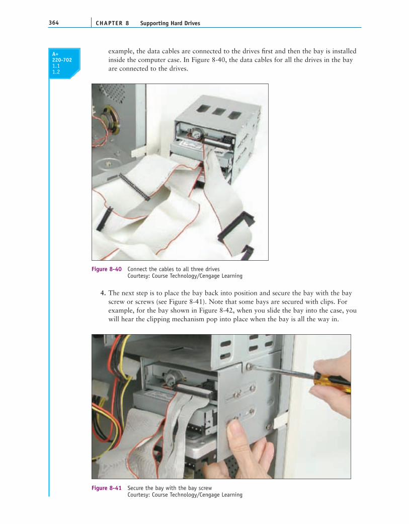
example, the data cables are connected to the drives first and then the bay is installedinside the computer case. In Figure 8-40, the data cables for all the drives in the bayare connected to the drives.
4. The next step is to place the bay back into position and secure the bay with the bayscrew or screws (see Figure 8-41). Note that some bays are secured with clips. Forexample, for the bay shown in Figure 8-42, when you slide the bay into the case, youwill hear the clipping mechanism pop into place when the bay is all the way in.
Figure 8-40 Connect the cables to all three drivesCourtesy: Course Technology/Cengage Learning
Figure 8-41 Secure the bay with the bay screwCourtesy: Course Technology/Cengage Learning

365How to Select and Install Hard Drives and Floppy Drives
8
A+ 220-702
A+220-7021.11.2
5. You can now install a power connection to each drive (Figure 8-43). In Figure 8-43,the floppy drive uses the small Berg power connection, and the other drives use thelarge Molex ones. It doesn’t matter which of the power cords you use, because they allproduce the same voltage. Also, the cord only goes into the connection one way.
Figure 8-42 Slide the bay into the case as far as it will goCourtesy: Course Technology/Cengage Learning
Figure 8-43 Connect a power cord to each driveCourtesy: Course Technology/Cengage Learning
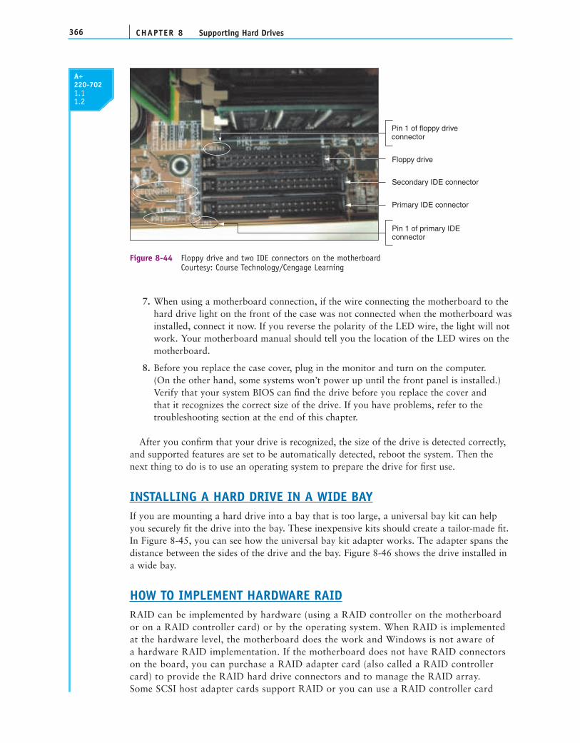
6. Next, connect the data cable to the IDE connector on the motherboard (see Figure 8-44).Make certain pin 1 and the edge color on the cable align correctly at both ends of thecable. Normally, pin 1 is closest to the power connection on the drive.
CHAPTER 8366 Supporting Hard Drives
A+220-7021.11.2
7. When using a motherboard connection, if the wire connecting the motherboard to thehard drive light on the front of the case was not connected when the motherboard wasinstalled, connect it now. If you reverse the polarity of the LED wire, the light will notwork. Your motherboard manual should tell you the location of the LED wires on themotherboard.
8. Before you replace the case cover, plug in the monitor and turn on the computer. (On the other hand, some systems won’t power up until the front panel is installed.)Verify that your system BIOS can find the drive before you replace the cover and that it recognizes the correct size of the drive. If you have problems, refer to thetroubleshooting section at the end of this chapter.
After you confirm that your drive is recognized, the size of the drive is detected correctly,and supported features are set to be automatically detected, reboot the system. Then thenext thing to do is to use an operating system to prepare the drive for first use.
INSTALLING A HARD DRIVE IN A WIDE BAYIf you are mounting a hard drive into a bay that is too large, a universal bay kit can helpyou securely fit the drive into the bay. These inexpensive kits should create a tailor-made fit.In Figure 8-45, you can see how the universal bay kit adapter works. The adapter spans thedistance between the sides of the drive and the bay. Figure 8-46 shows the drive installed ina wide bay.
HOW TO IMPLEMENT HARDWARE RAIDRAID can be implemented by hardware (using a RAID controller on the motherboardor on a RAID controller card) or by the operating system. When RAID is implementedat the hardware level, the motherboard does the work and Windows is not aware of a hardware RAID implementation. If the motherboard does not have RAID connectorson the board, you can purchase a RAID adapter card (also called a RAID controllercard) to provide the RAID hard drive connectors and to manage the RAID array. Some SCSI host adapter cards support RAID or you can use a RAID controller card
Primary IDE connector
Pin 1 of primary IDEconnector
Secondary IDE connector
Floppy drive
Pin 1 of floppy driveconnector
Figure 8-44 Floppy drive and two IDE connectors on the motherboardCourtesy: Course Technology/Cengage Learning

367How to Select and Install Hard Drives and Floppy Drives
8
A+ 220-702
A+220-7021.11.2
Figure 8-46 Hard drive installed in a wide bay using a universal bay kit adapterCourtesy: Course Technology/Cengage Learning
Side bracketsconnect to harddrive
Figure 8-45 Use the universal bay kit to make the drive fit the bayCourtesy: Course Technology/Cengage Learning
that provides IDE or serial ATA connectors. Figure 8-47 shows a RAID controller cardby Sabrent that provides four SATA ports.
A+ Exam Tip The A+ 220-702 Practical Application exam expects you to be able to detect problems,troubleshoot, and replace a RAID controller card.
Figure 8-48 shows a motherboard that has two regular IDE connectors, two serial ATAconnectors that can be configured for RAID, and two IDE RAID connectors. This boardsupports spanning, RAID 0, RAID 1, and a combination of RAID 0 and RAID 1 (calledRAID 0+1). For another motherboard, six SATA connectors on the motherboard can beused as RAID connectors if RAID is enabled in BIOS setup.
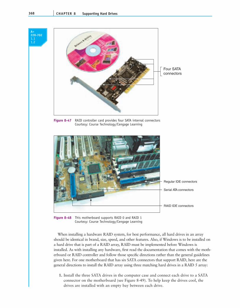
CHAPTER 8368 Supporting Hard Drives
A+220-7021.11.2
When installing a hardware RAID system, for best performance, all hard drives in an arrayshould be identical in brand, size, speed, and other features. Also, if Windows is to be installed ona hard drive that is part of a RAID array, RAID must be implemented before Windows isinstalled. As with installing any hardware, first read the documentation that comes with the moth-erboard or RAID controller and follow those specific directions rather than the general guidelinesgiven here. For one motherboard that has six SATA connectors that support RAID, here are thegeneral directions to install the RAID array using three matching hard drives in a RAID 5 array:
1. Install the three SATA drives in the computer case and connect each drive to a SATAconnector on the motherboard (see Figure 8-49). To help keep the drives cool, thedrives are installed with an empty bay between each drive.
Four SATAconnectors
Figure 8-47 RAID controller card provides four SATA internal connectorsCourtesy: Course Technology/Cengage Learning
Serial ATA connectors
Regular IDE connectors
RAID IDE connectors
Figure 8-48 This motherboard supports RAID 0 and RAID 1Courtesy: Course Technology/Cengage Learning

369How to Select and Install Hard Drives and Floppy Drives
8
A+ 220-702
A+220-7021.11.2
Three harddrives
Figure 8-49 Install three matching hard drives in a systemCourtesy: Course Technology/Cengage Learning
Figure 8-50 Configure SATA ports on the motherboard to enable RAIDCourtesy: Course Technology/Cengage Learning
2. Boot the system and enter BIOS setup. On the Advanced setup screen, verify the threedrives are recognized. Select the option to configure SATA and then select RAID fromthe menu (see Figure 8-50).
3. Reboot the system and a message is displayed on-screen: “Press <Ctrl-I> to enter theRAID Configuration Utility.” Press Ctrl and I to enter the utility (see Figure 8-51).

370
A+220-7021.11.2
Figure 8-51 BIOS utility to configure a RAID arrayCourtesy: Course Technology/Cengage Learning
Figure 8-52 Make your choices for the RAID arrayCourtesy: Course Technology/Cengage Learning
Notice in the information area that the three drives are recognized and their currentstatus is Non-RAID Disk.
4. Select option 1 to “Create RAID Volume.” On the next screen shown in Figure 8-52,enter a volume name (FileServer in our example).

371How to Select and Install Hard Drives and Floppy Drives
8
A+ 220-702
A+220-7021.11.2
5. Under RAID Level, select RAID5 (Parity). Because we are using RAID 5, whichrequires three hard drives, the option to select the disks for the array is not available.All three disks will be used in the array.
6. Select the value for the Strip Size. (This is the amount of space devoted to one stripacross the striped array. Choices are 32 KB, 64 KB, or 128 KB.)
7. Enter the size of the volume. The available size is shown in Figure 8-52 as 1192 GB,but you don’t have to use all the available space. The space you don’t use can later be configured as another array. (In this example, I entered 500 GB.)
8. Select Create Volume to complete the RAID configuration. A message appears warningyou, that if you proceed, all data on all three hard drives will be lost. Type Y tocontinue. The array is created and the system reboots.
You are now ready to install Windows. Do the following:
1. Boot from the Windows setup CD or DVD.
2. For Windows XP, at the beginning of Windows setup, you are given the opportunityto press F6 to install a RAID or SCSI driver. Press F6 and insert the RAID driver CDthat came bundled with the motherboard. Windows Vista does not require the RAIDdrivers and the installation proceeds as normal. (The details of installing Windows XPand Vista are covered in Chapter 12.)
Figure 8-53 shows the Disk Management window for this system immediately after Vistawas installed. Notice Vista recognizes one hard drive, which it partitioned and formattedduring the installation process as drive C:. The drive C: size is 500 GB, which is the amountof space that was dedicated to the RAID array. As far as Vista knows, there is a single 500 GB hard drive. BIOS is managing the RAID array without Vista’s awareness. If weinstall the RAID drivers that are found on the motherboard driver CD, then we can managethe RAID array from within Windows. Alternately, the RAID array can be managed fromthe BIOS utility by pressing Ctrl-I during the boot.
For file servers using RAID 5 that must work continuously and hold important data, it might be practical to use hardware that allows for hard drive hot-swapping, which meansyou can remove one hard drive and insert another without powering down the computer.However, hard drives that can be hot-swapped cost significantly more than regular harddrives. RAID hard drive arrays are sometimes used as part of a storage area network (SAN). A SAN is a network that has the primary purpose of providing large amounts of data storage.
RAID array
Figure 8-53 Vista Disk Management sees the RAID array as a single 500 GB hard driveCourtesy: Course Technology/Cengage Learning

A+220-7021.1 1.2
STEPS TO INSTALL A FLOPPY DRIVEMany computers today come with a hard drive and CD or DVD drive, but don’t include afloppy drive, although the motherboard most likely has a 34-pin floppy drive connector.Most computer cases also have one or more empty bays for a 31⁄2" floppy drive.
If you have no extra bay and want to add a floppy drive, you can attach an external drivethat comes in its own case and has its own power supply. Most external drives today connect to the main system using a USB port, such as the one in Figure 8-54.
Here are the steps to add or replace a floppy drive. Be sure to protect the computeragainst ESD as you work.
1. Turn off the computer, unplug the power cord, press the power button, and removethe cover.
2. Unplug the power cable to the old floppy drive. Steady the drive with one hand while youdislodge the power cable with the other hand. Unplug the data cable from the old drive.
3. Unscrew and dismount the drive. Some drives have one or two screws on each side thatattach the drive to the drive bay. After you remove the screws, the drive usually slides tothe front and out of the case. Sometimes, you must lift a catch underneath the drive as youslide the drive forward. Sometimes, the drive is installed into a removable bay. For thistype of case, first unscrew the screws securing the bay (most likely these screws are on thefront of the case) and remove the bay. Then unscrew and remove the drive from the bay.
4. Slide the new drive into the bay. Screw the drive down with the same screws used onthe old drive. Make sure the drive is anchored so that it cannot slide forward or backward, or up or down, even if a user turns the case on its side.
5. If you are adding (not replacing) a floppy drive, connect the floppy drive data cable tothe motherboard. Align the edge color of the ribbon cable with pin 1 on themotherboard connectors. Some connectors only allow you to insert the cable in onedirection. Be sure the end of the cable with the twist connects to the drive and the other end to the motherboard.
Figure 8-54 An external floppy drive uses a USB connectionCourtesy: Course Technology/Cengage Learning
Notes If your power supply doesn’t have the smaller Berg connector for the floppy drive, you canbuy a Molex-to-Berg converter to accommodate the floppy drive power connector.
CHAPTER 8372 Supporting Hard Drives
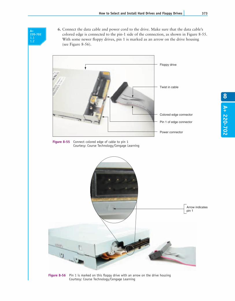
A+ 220-702373How to Select and Install Hard Drives and Floppy Drives
8
6. Connect the data cable and power cord to the drive. Make sure that the data cable’scolored edge is connected to the pin-1 side of the connection, as shown in Figure 8-55.With some newer floppy drives, pin 1 is marked as an arrow on the drive housing (see Figure 8-56).
Floppy drive
Pin 1 of edge connector
Twist in cable
Power connector
Colored edge connector
Figure 8-55 Connect colored edge of cable to pin 1Courtesy: Course Technology/Cengage Learning
Arrow indicatespin 1
Figure 8-56 Pin 1 is marked on this floppy drive with an arrow on the drive housingCourtesy: Course Technology/Cengage Learning
A+220-7021.1 1.2
CHAPTER 8374 Supporting Hard Drives
Most connections on floppy drives are oriented the same way, so this one probably hasthe same orientation as the old drive. The power cable goes into the power connectionin only one direction. Be careful not to offset the connection by one pin.
7. Replace the cover, turn on the computer, and enter BIOS setup to verify the drive is recognized with no errors. If you are adding (not replacing) a floppy drive,you must inform BIOS setup by accessing setup and changing the drive type. Boot to the Windows desktop and test the drive by formatting a disk or copyingdata to a disk.
TROUBLESHOOTING HARD DRIVES
In this part of the chapter, you’ll learn how to troubleshoot problems with hard drivesand floppy drives. The following sections cover problems with hard drive installations,and problems that occur after the installation with hard drives and floppy drives.Problems with booting the PC caused by hard drive hardware are also covered. How todeal with problems caused by a corrupted Windows installation is covered in Chapters15 and 16.
PROBLEMS WITH HARD DRIVE INSTALLATIONSSometimes, trouble crops up during an installation. Keeping a cool head, thinking thingsthrough carefully a second, third, and fourth time, and using all available resources willmost likely get you out of any mess.
Installing a hard drive is not difficult, unless you have an unusually complex situation.For example, your first hard drive installation should not involve the intricacies of installinga second SCSI drive in a system that has two SCSI host adapters. Nor should you install a
second drive in a system that uses an IDE connection for onedrive on the motherboard and an adapter card in an expan-sion slot for the other drive. If a complicated installation isnecessary and you have never installed a hard drive, ask forexpert help.
The following list describes the errors that cropped up during a few hard driveinstallations; the list also includes the causes of the errors, and what was done about them.Everyone learns something new when making mistakes, and you probably will, too. You canthen add your own experiences to this list.
Shawn physically installed an IDE hard drive. He turned on the machine and accessedBIOS setup. The hard drive was not listed as an installed device. He checked anddiscovered that autodetection was not enabled. He enabled it and rebooted. Setuprecognized the drive.When first turning on a previously working PC, John received the following errormessage: “Hard drive not found.” He turned off the machine, checked all cables, and
Notes Note that you can turn on the PC and test the drive before you replace the computer casecover. If the drive doesn’t work, having the cover off makes it easier to turn off the computer, checkconnections, and try again. Just make certain that you don’t touch anything inside the case while thecomputer is on. Leaving the computer on while you disconnect and reconnect a cable is very dangerousfor the PC and will probably damage something—including you!
Installing a Second Hard DriveVideo
A+220-7021.2
A+220-7021.1 1.2

375Troubleshooting Hard Drives
8
A+ 220-702
A+220-7021.2
discovered that the data cable from the motherboard to the drive was loose. Hereseated the cable and rebooted. POST found the drive.Lucia physically installed a new hard drive, replaced the cover on the computer case,and booted the PC with a Windows setup CD in the drive. POST beeped three timesand stopped. Recall that diagnostics during POST are often communicated by beeps ifthe tests take place before POST has checked video and made it available to displaythe messages. Three beeps on most computers signal a memory error. Lucia turned offthe computer and checked the memory modules on the motherboard. A modulepositioned at the edge of the motherboard next to the cover had been bumped as shereplaced the cover. She reseated the module and booted again, this time with the coverstill off. The error disappeared.Jason physically installed a new hard drive and turned on the computer. Hereceived the following error: “No boot device available.” He forgot to insert aWindows setup CD. He put the disc in the drive and rebooted the machinesuccessfully.The hard drive did not physically fit into the bay. The screw holes did not line up.Juan got a bay kit, but it just didn’t seem to work. He took a break, went to lunch,and came back to make a fresh start. Juan asked others to help view the brackets,holes, and screws from a fresh perspective. It didn’t take long to discover that he hadoverlooked the correct position for the brackets in the bay.Maria set the jumpers on a PATA hard drive and physically installed the drive. Shebooted and received the following error message: “Hard drive not present.” Sherechecked all physical connections and found everything okay. After checking thejumper settings, she realized that she had set them as if this were the second drive of atwo-drive system, when it was the only drive. She restored the jumpers to theiroriginal state. In this case, as in most cases, the jumpers were set at the factory to becorrect when the drive is the only drive.
If BIOS setup does not recognize a newly installed hard drive, check the following:
Has BIOS setup been correctly configured for autodetection?Are the jumpers on the drive set correctly?Have the power cord and data cable been properly connected? Verify that each issolidly connected at both ends.Check the Web site of the drive manufacturer for suggestions, if the above steps don’tsolve your problem. Look for diagnostic software that can be downloaded from theWeb site and used to check the drive.
A+ Exam Tip The A+ 220-702 Practical Application exam might give you a symptom and expectyou to select a probable source of a problem from a list of sources. These examples of what can gowrong can help you connect problem sources to symptoms.
Caution One last warning: When things are not going well, you can tense up and makemistakes more easily. Be certain to turn off the machine before doing anything inside! Not doing socan be a costly error. For example, a friend had been trying and retrying to boot for some time, andgot frustrated and careless. He plugged the power cord into the drive without turning the PC off. Themachine began to smoke and everything went dead. The next thing he learned was how to replace apower supply!
CHAPTER 8376 Supporting Hard Drives
A+220-7021.2
HOW TO APPROACH A HARD DRIVE PROBLEMAFTER THE INSTALLATIONAfter the hard drive is working, problems can arise later, such as corrupted data files, acorrupted Windows installation, or a hardware problem that causes the system to refuseto boot. In this section, you’ll learn about some tools you can use to solve hard driveproblems and how to approach the problem and prioritize what to do first. Then, inlater sections, we’ll look at some specific error messages and symptoms and how to dealwith them.
START WITH THE END USERWhen an end user brings a problem to you, begin the troubleshooting process by interview-ing the user. When you interview the user, you might want to include these questions:
Can you describe the problem and describe when it occurs?Was the computer recently moved?Was any new hardware or software recently installed?Was any software recently reconfigured or upgraded?Did someone else use your computer recently?Does the computer have a history of similar problems?Is there important data on the drive that is not backed up?Can you show me how to reproduce the problem?
After you gather this basic information, you can prioritize what to do and begin diagnos-ing and addressing the hard drive problems.
PRIORITIZE WHAT YOU HAVE LEARNEDIf a hard drive is not functioning and data is not accessible, setting priorities helps focusyour work. For most users, data is the first priority unless they have a recent backup.Software can also be a priority if it is not backed up. Reloading software from the originalinstallation disks or CD can be time consuming, especially if the configuration is complex orsoftware macros or scripts are on the drive and not backed up.
If a system won’t boot from the hard drive, your first priority might be to recover data onthe drive. Therefore, before you try to solve the hardware or Windows problem thatprevents booting, consider removing the drive and installing it as a second drive in a work-ing system. If the partition table on the problem drive is intact, you might be able to copydata from the drive to the primary drive in the working system. Then turn your attention tosolving the original problem.
If you have good backups of both data and software, hardware might be your priority. Itcould be expensive to replace, but downtime can be costly, too. The point is, when troublearises, determine your main priority and start by focusing on that.
BE AWARE OF AVAILABLE RESOURCESBe aware of the resources available to help you resolve a problem:
User manuals often list error messages and their meanings.Installation manuals most likely will have a troubleshooting section and list anydiagnostic tools available.

377Troubleshooting Hard Drives
8
A+ 220-702
A+220-7021.2
The Internet can also help you diagnose hardware and software problems. Go to theWeb site of the product manufacturer, and search for the FAQs (frequently askedquestions) list or a support forum. It’s likely that others have encountered the sameproblem and posted the question and answer. If you search and cannot find youranswer, you can post a new question. Use a search engine such as www.google.com tosearch for the error, the hardware device, the problem, the technology used, and otherkeywords that can help you find useful information. Many technicians enjoy sharingwhat they know online, and the Internet can be a rich source of all kinds of technicalinformation and advice. Be careful, however. Not all technical advice is correct or wellintentioned.Training materials can offer insights, explain concepts and tools, and give you ageneral direction as to how to approach a problem.Telephone, chat, or e-mail technical support from the hardware and softwaremanufacturers can help you interpret an error message, or it can provide generalsupport in diagnosing a problem. Most technical support is available duringworking hours by telephone. Check your documentation for telephone numbers.An experienced computer troubleshooter once said, “The people who solvecomputer problems do it by trying something and making phone calls, tryingsomething else and making more phone calls, and so on, until the problem is solved.”PartitionMagic by Symantec (www.symantec.com) lets you manage partitions on ahard drive for Windows XP. You can change the size of partitions and move partitionswithout losing data while you work. You can switch file systems without disturbingyour data, and you can hide and show partitions to secure your data. For Vista, DiskManagement performs many of the same functions.SpinRite by Gibson Research (www.grc.com) is hard drive utility software that hasbeen around for years. Still a DOS application without a sophisticated GUIinterface, SpinRite has been updated to adjust to new drive technologies. Itsupports NTFS, FAT32, and SCSI drives. It can be installed and run from anybootable device, including a CD, USB drive, or floppy disk, which means that itdoesn’t require much system overhead. Because it is written in a language closer tothe binary code that the computer understands, it is more likely to detect underly-ing hard drive problems than software that uses Windows, which can stand as amasking layer between the software and the hard drive. SpinRite analyzes theentire hard drive surface, performing data recovery of corrupted files and filesystem information. Sometimes, SpinRite can recover data from a failing hard drivewhen other software fails.GetDataBack by Runtime Software (www.runtime.org) can recover data and programfiles even when Windows cannot recognize the drive. It can read NTFS and FAT32 filesystems and can solve problems with a corrupted partition table, boot record, or rootdirectory.Hard drive manufacturer’s diagnostic software is available for download from the Web sites of many hard drive manufacturers. For example, you can download Data Lifeguard Diagnostic for DOS from the Western Digital Web site (www.wdc.com), burn the software to CD, and boot from the CD (see Figure 8-57). Using the software, you can do a quick test to check WesternDigital drives for physical problems or an extended test to repair any correctableproblems. You can also write zeros to every sector on the drive to get a fresh startwith the drive. There’s also a Windows version that can be used to test a secondhard drive in your system. Another similar program is SeaTools by Seagate
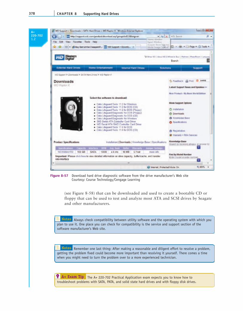
CHAPTER 8378 Supporting Hard Drives
A+220-7021.2
Figure 8-57 Download hard drive diagnostic software from the drive manufacturer’s Web siteCourtesy: Course Technology/Cengage Learning
(see Figure 8-58) that can be downloaded and used to create a bootable CD orfloppy that can be used to test and analyze most ATA and SCSI drives by Seagateand other manufacturers.
Notes Always check compatibility between utility software and the operating system with which youplan to use it. One place you can check for compatibility is the service and support section of the software manufacturer’s Web site.
Notes Remember one last thing: After making a reasonable and diligent effort to resolve a problem,getting the problem fixed could become more important than resolving it yourself. There comes a timewhen you might need to turn the problem over to a more experienced technician.
A+ Exam Tip The A+ 220-702 Practical Application exam expects you to know how totroubleshoot problems with SATA, PATA, and solid state hard drives and with floppy disk drives.

379Troubleshooting Hard Drives
8
A+ 220-702
A+220-7021.2
BOOT PROBLEMS CAUSED BY HARD DRIVE HARDWAREIn this section, we look at different problems with the hard drive that present themselvesduring the boot. These problems can be caused by the hard drive subsystem, by the partitiontable or file system on the drive, or by files required for the OS to boot. When trying tosolve a problem with the boot, you need to decide if the problem is caused by hardware orsoftware. All the problems discussed in this section are caused by hardware. In Chapters 15and 16, you’ll learn how to deal with problems that cause errors when loading the operatingsystem and problems with missing or corrupted data files. All these type errors are causedby software.
PROBLEMS AT POSTRecall from Chapter 5 that the BIOS performs the POST at the beginning of the boot to verify that essential hardware devices are working. Hardware problems usually show up at POST, unless there is physical damage to an area of the hard drive that is not accessed during POST. Hardware problems often make the hard
Figure 8-58 Use SeaTools by Seagate to create a diagnostic CD or floppy to test and analyze hard drivesCourtesy: Course Technology/Cengage Learning
A+220-7021.22.32.4
CHAPTER 8380 Supporting Hard Drives
drive totally inaccessible. If BIOS cannot find a hard drive at POST, it displays an error message similar to this:
Hard drive not found
Fixed disk error
Invalid boot disk
Inaccessible boot device
Inaccessible boot drive
Numeric error codes in the 1700s or 10400s
The reasons BIOS cannot access the drive can be caused by the drive, the data cable, the electrical system, the motherboard, the controller card (if one is present), or a looseconnection. Here is a list of things to do and check:
1. If BIOS displays numeric error codes or cryptic messages during POST, check theWeb site of the BIOS manufacturer for explanations of these codes or messages.
2. For a RAID array, use the BIOS utility to check the status of each disk in the arrayand to check for errors.
3. In BIOS setup, look for the ability to disable block mode. Block mode speeds upaccess time by allowing blocks of data to be read from the drive at one time.Disabling it will slow down drive performance but might solve the problem.
4. Remove and reattach all drive cables. Check for correct pin-1 orientation.
5. If you’re using a RAID, eSATA, SATA, PATA, or SCSI controller card, remove andreseat it or place it in a different slot. Check the documentation for the card, lookingfor directions for troubleshooting.
6. Check the jumper settings on the drive.
7. Inspect the drive for damage, such as bent pins on the connection for the cable.
8. Determine if the hard drive is spinning by listening to it or lightly touching the metaldrive (with power on).
9. Check the cable for frayed edges or other damage.
10. Check the installation manual for things you might have overlooked. Look for asection about system setup, and carefully follow all directions that apply.
11. Be sure the power cable and drive data cable connections are good.
12. Check BIOS setup for errors in the hard drive configuration. If you suspect anerror, set CMOS to default settings, make sure autodetection is turned on, andreboot the system.
13. Try booting from another media such as the Windows setup CD. If you can boot usinganother media, you have proven that the problem is isolated to the hard drive subsystem.Windows recovery tools to use from the setup CD are covered in Chapters 15 and 16.
14. Check the drive manufacturer Web site for diagnostic software. Run the software totest the drive for errors.
15. If it is not convenient to create a boot CD with hard drive diagnostic softwareinstalled, you can move the drive to a working computer and install it as a second
A+220-7021.22.32.4

381Troubleshooting Hard Drives
8
A+ 220-702
A+220-7021.22.32.4
drive in the system. Then you can use the diagnostic software installed on theprimary hard drive to test the problem drive. While you have the drive installed in aworking computer, be sure to find out if you can copy data from it to the good drive,so that you can recover any data not backed up. Note that for these temporary tests,you don’t have to physically install the drive in the working system. Open the com-puter case. Carefully lay the drive on the case and connect a power cord and datacable (see Figure 8-59). Then turn on the PC. While you have the PC turned on, bevery careful to not touch the drive or touch inside the case. Also, while a tower caseis lying on its side like the one in Figure 8-59, don’t use the CD or DVD drive.
16. If the drive still does not boot, exchange the three field replaceable units—the datacable, the adapter card (optional), and the hard drive itself—for a hard drivesubsystem. Do the following, in order:
Reconnect or swap the drive data cable.Reseat or exchange the drive controller card, if one is present.Exchange the hard drive for a known good unit.
17. If the hard drive refuses to work but its light stays on even after the system has fullybooted, the problem might be a faulty controller on the hard drive or motherboard.Try replacing the hard drive. Next, try an ATA controller card to substitute for theATA connectors on the motherboard or replace the motherboard.
18. Sometimes older drives refuse to spin at POST. Drives that have trouble spinningoften whine at startup for several months before they finally refuse to spin altogether.If your drive whines loudly when you first turn on the computer, never turn off thecomputer. One of the worst things you can do for a drive that is having difficultystarting up is to leave the computer turned off for an extended period of time. Somedrives, like old cars, refuse to start if they are unused for a long time.
Figure 8-59 Temporarily connect a faulty hard drive to another system to diagnose the problemand try to recover dataCourtesy: Course Technology/Cengage Learning

CHAPTER 8382 Supporting Hard Drives
A+220-7021.2 2.32.4
A bad power supply or a bad motherboard also might cause a disk boot failure. If theproblem is solved by exchanging one of the field replaceable units listed, you still mustreinstall the old unit to verify that the problem was not caused by a bad connection.
BUMPS ARE BAD!The read/write heads at the ends of the read/write arms on a hard drive get extremely closeto the platters, but do not actually touch them. This minute clearance between the heads
Notes You can purchase an inexpensive converter such as the one in Figure 8-60 to connect afailing PATA hard drive to a working computer using a USB port. The kit also comes with a converter for a notebook hard drive. (A PATA connector on a laptop is shorter than a desktop PATA connector.)Figure 8-61 shows a SATA to USB converter kit. The SATA connector can be used for desktop or laptophard drives because a SATA connector is the same for both. These ATA to USB converters are really handywhen troubleshooting problems with hard drives that refuse to boot.
40-pin IDEconnector
Driver CD
Converter fornotebook harddrives
Power connectorfor hard drive
USB connector
Connects to USB port
Connects to drive
Power to drive
Figure 8-60 Use an IDE to USB converter for diagnostic testing and to recover data from a failing PATA hard driveCourtesy: Course Technology/Cengage Learning
Figure 8-61 Use a SATA to USB converter to recover data from a drive using a SATA connector Courtesy: Course Technology/Cengage Learning

383Troubleshooting Hard Drives
8
A+ 220-702
A+220-7021.22.32.4
and platters makes hard drives susceptible to destruction. Should a computer be bumped ormoved while the hard drive is operating, a head can easily bump against the platter andscratch the surface. Such an accident causes a “hard drive crash,” often making the harddrive unusable.
If the head mechanism is damaged, the drive and its data are probably total losses. If thefirst tracks that contain the partition table, boot record, MFT (for the NTFS file system), orroot directory are damaged, the drive could be inaccessible, although the data might beunharmed.
Here’s a trick that might work for a hard drive whose head mechanism is intact butwhose first few tracks are damaged. First, find a working hard drive that has the samepartition table information as the bad drive. Take the computer case off, place the gooddrive on top of the bad drive housing, and connect a spare power cord and the ATA datacable to the good drive. Leave a power cord connected to the bad drive. Boot from abootable CD or floppy disk. No error message should show at POST. Access the gooddrive by entering C: at the command prompt. The C prompt should show on themonitor screen.
Without turning off the power, gently remove the data cable from the good drive and place it on the bad drive. Do not disturb the power cords on either drive or touchchips on the drive logic boards. Immediately copy the data you need from the bad drive to another media, using the Copy command. If the area of the drive where the data is stored, the FAT or MFT, and the directory are not damaged, this methodshould work.
Here’s another trick for an older hard drive having trouble spinning when first turned on.Remove the drive from the case, hold it firmly in both hands, and give the drive a quick andsudden twist that forces the platters to turn inside the drive housing. Reinstall the drive. Itmight take several tries to get the drive spinning. After the drive is working, immediatelymake a backup and plan to replace the drive soon.
INVALID DRIVE OR DRIVE SPECIFICATIONIf you get the error message “Invalid drive or drive specification,” the system BIOS cannotread the partition table information. You’ll need to boot from the Windows setup CD orDVD and check the partition table. How to do that is covered in Chapters 15 and 16.
BAD SECTOR ERRORSTrack and sector markings on a drive sometimes “fade” off the hard drive over time,which causes “bad sector” errors to crop up. These errors can also occur if an area ofthe drive has become damaged. Do not trust valuable data to a drive that has this kindof trouble. Plan to replace the drive soon. In the meantime, make frequent backups and leave the power on. You’ll learn more about this and other software errors in later chapters.
SOLID STATE DRIVESRecall that solid state drives have no moving parts, so you don’t have to be concerned withbumping the drive while it is in use. They might come from the factory already partitionedand formatted using the NTFS file system, or you might have to format them yourself. If thedrive gives errors, try using diagnostic software specific for this drive if it is available fromthe drive manufacturer. Also check the support section of the Web site for troubleshootingtips. SATA and PATA connections and BIOS settings for solid state drives look and work thesame as for other drives.
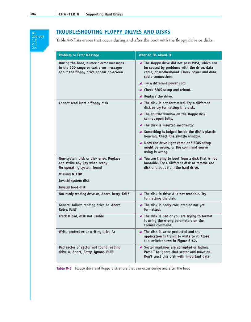
CHAPTER 8384 Supporting Hard Drives
A+220-7021.22.32.4
During the boot, numeric error messages The floppy drive did not pass POST, which can in the 600 range or text error messages be caused by problems with the drive, data about the floppy drive appear on-screen. cable, or motherboard. Check power and data
cable connections.
Try a different power cord.
Check BIOS setup and reboot.
Replace the drive.
Cannot read from a floppy disk The disk is not formatted. Try a different disk or try formatting this disk.
The shuttle window on the floppy disk cannot open fully.
The disk is inserted incorrectly.
Something is lodged inside the disk’s plastichousing. Check the shuttle window.
Does the drive light come on? BIOS setup might be wrong, or the command you’re using is wrong.
Non-system disk or disk error. Replace You are trying to boot from a disk that is not and strike any key when ready. bootable. Try a different disk or remove the No operating system found disk and boot from the hard drive.
Missing NTLDR
Invalid system disk
Invalid boot disk
Not ready reading drive A:, Abort, Retry, Fail? The disk in drive A is not readable. Try formatting the disk.
General failure reading drive A:, Abort, The disk is badly corrupted or not yet Retry, Fail? formatted.
Track 0 bad, disk not usable The disk is bad or you are trying to format it using the wrong parameters on the Format command.
Write-protect error writing drive A: The disk is write-protected and the application is trying to write to it. Close the switch shown in Figure 8-62.
Bad sector or sector not found reading Sector markings are corrupted or fading. drive A, Abort, Retry, Ignore, Fail? Press I to ignore that sector and move on.
Don’t trust this disk with important data.
Problem or Error Message What to Do About It
Table 8-5 Floppy drive and floppy disk errors that can occur during and after the boot
TROUBLESHOOTING FLOPPY DRIVES AND DISKSTable 8-5 lists errors that occur during and after the boot with the floppy drive or disks.

385Chapter Summary
8
A+220-7021.22.32.4
>> CHAPTER SUMMARY
A hard disk drive (HDD) comes in two sizes: 3.5" for desktop computers, and 2.5" for laptops.
A hard drive can be a magnetic drive, a solid state drive, or a hybrid drive. A solid statedrive is more expensive, faster, more reliable, and uses less power than a magnetic drive.
A hard drive is low-level formatted at the factory where track and sector markings arewritten to the drive. Drive capacity is measured in GB or TB.
When Windows prepares a drive as a basic disk, it installs a Master Boot Record (MBR)which contains a partition table and a master boot program.
A primary partition is also called a volume, simple volume, or basic volume. An extendedpartition can have more than one logical drive.
Two file systems used for hard drives are FAT32 (the older system) and NTFS (the newersystem).
Most hard drives use the ATA interface standards. The two main categories of ATA areparallel ATA and serial ATA. Serial ATA is easier to configure and better performing thanPATA. External SATA ports are called eSATA ports.
S.M.A.R.T. is a self-monitoring technology whereby the BIOS monitors the health of thehard drive and warns of an impending failure.
ATAPI standards are used by optical drives and other drives that use the ATA interface on a motherboard or controller card.
Several PATA standards are Fast ATA, Ultra ATA, Ultra ATA/66, Ultra ATA/100, andUltra ATA/133.
Write-protected
Write-enabled
Figure 8-62 For you to write to a disk, the write-protect notch must be closedCourtesy: Course Technology/Cengage Learning

CHAPTER 8386 Supporting Hard Drives
Three SATA standards provide data transfer rates of 1.5 Gb/sec, 3.0 Gb/sec, and 6.0 Gb/sec.Currently, the second standard is the most popular and is sometimes called SATA-300.
SCSI is an interface standard for high-end hard drives used in servers.
RAID technology uses an array of hard drives used to provide fault tolerance and/orimprovement in performance.
Today’s floppy disks are 31⁄2", high-density disks that hold 1.44 MB of data.
When selecting a hard drive, consider the capacity of the drive, the spindle speed (formagnetic drives), the interface standard used, the cache or buffer size, and the averageseek time. Also, solid state or hybrid drives are faster than magnetic drives.
SATA drives require no configuration and are installed using a power cord and a singleSATA data cable.
PATA drives require you to set a jumper to determine if the drive will be the master orslave on a single cable. The PATA cable can accommodate two drives. A PATA motherboard has two PATA connectors for a total of four PATA drives in the system.
After a hard drive is installed, verify it is recognized by BIOS and then use Windows topartition and format the drive. Solid state drives might be preformatted using the NTFSfile system.
Hardware RAID can be implemented by the motherboard or a RAID controller card.Software RAID is implemented by Vista or Windows XP. Best practice is to use hardwareRAID rather than software RAID.
After a floppy disk drive is installed, you must configure the drive in BIOS setup.
>> KEY TERMS
80-conductor IDE cableactive partitionANSI (American National
Standards Institute)ATAPI (Advanced
Technology Attachment Packet Interface)
autodetectionbasic diskblock modeboot recordboot sectorclusterDMA (direct memory access)
transfer modedrive imageEIDE (Enhanced IDE)extended partitionexternal SATA (eSATA)FAT12fault tolerancefile allocation table (FAT)file allocation unitfile systemfloppy disk drive (FDD)
formattinghard disk drive (HDD)hard driveheadhigh-level formattinghost adapterhot-plugginghot-swappinghybrid hard drivesIntegrated Device Electronics Logical Unit Number (LUN)logical driveslow-level formattingmagnetic hard drivemirrored volumeNew Technology file system
(NTFS)operating system formattingparallel ATAPIO (Programmed Input/Output)
transfer modeprimary partitionRAID (redundant array of
inexpensive disks or redundantarray of independent disks)
RAID 0RAID 1RAID 5RAID-5 volumesread/write headReadyDriveSCSI IDSCSI host adapter cardserial ATA (SATA)serial ATA cableserial attached SCSI (SAS)simple volumeS.M.A.R.T. (Self-Monitoring
Analysis and ReportingTechnology)
solid state device (SSD)solid state drive (SSD)spanningstriped volumeterminating resistorvolume
For explanations of key terms, see the Glossary near the end of the book.
387Reviewing the Basics
8
>> REVIEWING THE BASICS
1. What are the two common sizes for hard drives?
2. Why is a solid state drive referred to as solid state?
3. If a magnetic drive has four platters, how many heads does it have?
4. What is the name of the Vista technology that supports a hybrid drive?
5. When the OS addresses the sectors on a hard drive as one long list of sequential sectors,what is this technology called?
6. What are the main two components of the Master Boot Record on a hard drive?
7. What is the smallest unit of space on a hard drive that can be used to store a file?
8. What two file systems can Windows use to format a hard drive? Which system supportsthe most storage capacity?
9. Which ATA standard for hard drives first introduced S.M.A.R.T.?
10. Which ATA standard is the latest standard that made improvements to PATA?
11. A CD drive that uses a PATA connection must follow what standard?
12. How many pins does a PATA cable have? What is the maximum recommended length of a PATA cable?
13. What transfer mode can transmit data from a device to memory without involving the CPU?
14. What term describes the technology that allows you to exchange a hard drive withoutpowering down the system?
15. Which RAID level mirrors one hard drive with a second drive so that the same data is written to both drives?
16. Which RAID level stripes data across multiple drives to improve performance and alsoprovides fault tolerance?
17. How many pins does a floppy drive cable have?
18. Which file system does a floppy disk use?
19. What are three current ratings for spindle speed for a magnetic hard drive?
20. What Windows utility can be used to partition and format a hard drive?
21. What are the four possible configurations for a PATA drive installed in a system?
22. If a motherboard has one blue IDE connector and one black IDE connection, which do you use to install a single drive?
23. When implementing RAID on a motherboard, where do you enable the feature?
24. To write to a floppy disk, is it necessary for the write-protect notch to be open orclosed?
25. What is the name of the Seagate utility that can be used to test a hard drive and diagnose a hard drive problem?

CHAPTER 8388 Supporting Hard Drives
>> THINKING CRITICALLY
1. You install a hard drive and then turn on the PC for the first time. You access BIOSsetup and see that the drive is not recognized. Which of the following do you do next?
a. Turn off the PC, open the case, and verify that memory modules on the motherboardhave not become loose.
b. Turn off the PC, open the case, and verify that the data cable and power cable areconnected correctly and jumpers on the drive are set correctly.
c. Verify that BIOS autodetection is enabled.
d. Reboot the PC and enter BIOS setup again to see if it now recognizes the drive.
2. Most motherboards that use SATA connectors have at least one PATA connector on theboard. What is the most important reason this PATA connector is present?
a. The hard drive used for booting the OS must use a PATA connector.
b. The IDE controller will not work without at least one PATA connector.
c. The board can accommodate older hard drives using the PATA connector.
d. The PATA connector can be used for EIDE drives such as a CD or DVD drive.
3. You want to set up your desktop system to use a solid state drive, but the only solid state drivesyou can find are 2.5" drives intended for laptops. Which of the following do you do?
a. Buy a laptop computer with a solid state drive.
b. Buy a bay adapter that will allow you to install a 2.5" drive in a desktop case bay.
c. Flash BIOS so that your system will support a laptop hard drive.
d. Use a special SATA controller card that will support a laptop hard drive.
>> HANDS-ON PROJECTS
PROJECT 8-1: Examining the BIOS Setting for a Hard Drive
From the BIOS setup information on your computer, write down or print all the BIOSsettings that apply to your hard drive. Explain each setting that you can. What is the sizeof the installed drive?
PROJECT 8-2: Selecting a Replacement Hard Drive
Suppose the 640-GB Western Digital hard drive installed in the RAID array and shown inFigure 8-49 has failed. Search the Internet and find a replacement drive as close to this driveas possible. Print three Web pages showing the sizes, features, and prices of three possiblereplacements. Which drive would you recommend as the replacement drive and why?
PROJECT 8-3: Preparing for Hard Drive Hardware Problems
1. Boot your PC and make certain that it works properly. Turn off your computer, remove the computer case, and disconnect the data cable to your hard drive. Turn on the computer again. Write down the message that you get.

389Real Problems, Real Solutions
8
2. Turn off the computer and reconnect the data cable. Reboot and make sure the system isworking again.
3. Turn off the computer and disconnect the power supply cord to the hard drive. Turn onthe computer. Write down the error that you get.
4. Turn off the computer, reconnect the power supply, and reboot the system. Verify thesystem is working again.
PROJECT 8-4: Researching with the Internet
Suppose a friend has asked you to install an old hard drive in his computer. The drive is theMaxtor Quantum Fireball Plus AS 20.5-GB hard drive. You want the drive to be the slavedrive, and you know that you must change the current jumper settings. The four jumpers on thedrive are labeled DS, CS, PK, and Rsvd. The description of the jumpers doesn’t tell you how toset the jumpers so the drive is the slave. The documentation is not available. What do you do?
The best solution is to use the Internet to access the drive manufacturer’s Web site forthis information. In this case, the site is www.maxtor.com. Use this example or someother example given by your instructor to determine the correct settings for the jumpers.
PROJECT 8-5: Researching Floppy Drives on the Internet
Use the Internet to answer the following questions:
What is the price of an internal floppy drive?
What kind of connections do external floppy disk drives use? What is the price of an external drive?
Why do you think external drives cost more than internal drives? What are theadvantages of external drives? Internal drives?
PROJECT 8-6: Installing a Hard Drive
In a lab that has one hard drive per computer, you can practice installing a hard drive byremoving a drive from one computer and installing it as a second drive in another computer.When you boot up the computer with two drives, verify that both drives are accessible inWindows Explorer. Then remove the second hard drive, and return it to its originalcomputer. Verify that both computers and drives are working.
>> REAL PROBLEMS, REAL SOLUTIONS
REAL PROBLEM 8-1: Data Recovery Problem
Your friend has a Windows XP desktop system that contains important data. He franticallycalls you to say that when he turns on the computer, the lights on the front panel light upand he can hear the fan spin for a moment and then all goes dead. His most urgent problemis the data on his hard drive, which is not backed up. The data is located in several folderson the drive. What is the quickest and easiest way to solve the most urgent problem,recovering the data? List the major steps in that process.
CHAPTER 8390 Supporting Hard Drives
REAL PROBLEM 8-2: Salvaging Valuable Data on a Floppy Disk
On the job as a PC repair technician at a local university, a distraught student comes to youin a panic. Susan shows you the plastic housing of her floppy disk has been chipped andcracked so she can’t insert it into a floppy disk drive. The problem is it holds her only copyof her term paper that is due tomorrow! She desperately needs your help.
You examine the floppy disk and confirm that, yes, the housing is completelydestroyed. You ask her how that happened and she begins to turn red as she describes avery vindictive little brother. You begin to feel sorry for her and decide to take the timeto help. You notice the disk inside the housing appears to be in good shape. Can youremove the disk from the floppy disk housing and carefully place it in a new housing soshe can insert it in a floppy disk drive? Test your theory by removing a floppy disk thathas data written to it from one housing, putting it into another housing, and thenreading the data on the disk.
REAL PROBLEM 8-3: Using Hardware RAID
You work as a PC technician for a boss who believes you are really bright and can solve justabout any problem he throws at you. Folks in the company have complained one time toomany that the file server downtime is just killing them, so he asks you to solve this problem.He wants you to figure out what hardware is needed to implement hardware RAID for faulttolerance. Here are the first steps you take:
1. You check the file server’s configuration and discover it has a single hard drive using aserial ATA connection with Windows Server 2003 installed. There are four empty bays inthe computer case and four extra 4-pin power cords.
2. You discover the server’s motherboard has an empty PCIe x4 slot. You think the slotmight accommodate a RAID controller.
3. After doing a little searching on the Web, you find the Intel RAID Controller SASMF8I(http://www.intel.com/products/server/raid-controllers/sasmf8i/sasmf8i-overview.htm).You think it might work.
4. The next steps are to read the documentation about this controller, and then decide onwhich RAID configuration you should use and how many and what kind of hard drivesyou should buy.
Complete the investigation and do the following:
1. Decide what hardware you must purchase and print Web pages showing the productsand their cost.
2. What levels of RAID does this controller support? Which RAID level is best to use? Printany important information in the RAID controller documentation that supports yourdecisions. If you prefer, you can recommend a different RAID controller.
3. What is the total hardware cost of implementing RAID? Estimate how much time youthink it will take for you to install the devices and test the setup.


