CHAPTER! Reviews of Elastic Properties of Solids and...
44
CHAPTER! Reviews of Elastic Properties of Solids and Ceramic Materials A: Elastic Properties of Solids 1.1 : Introduction The impact of solids on the world of science and technology has been enormous, covering such diverse applications as solar energy, image processing, energy storage, computer and telecommunication technology, thermoelectric energy conversion and new materials for numerous applications. The disordered phases of condensed matter are far more abundant, and of no less technological value than the idealized single crystals [1-2]. The technological importance of amorphous solids has mushroomed over the past few years due to the discovery of some surprising anomalies in the acoustic, electric and thermodynamic [3-4] behaviour of these materials. The study of these amorphous solids offers new frontiers of research and hopefully, promise for more technological developments. In solid state physics, the structure determines the mechanical properties of the material, the phonon modes of solid determines the thermal properties of the material and electron structure controls the electrical and optical properties the material [5-8]. The crystalline solids posses a definite periodicity and long-range order, while amorphous materials exhibit only a short-range order [SRO] and atoms/molecules do not possess periodicity. Models of amorphous solids exhibiting I
-
Upload
vuongnguyet -
Category
Documents
-
view
221 -
download
0
Transcript of CHAPTER! Reviews of Elastic Properties of Solids and...

CHAPTER!
Reviews of Elastic Properties of Solids and
Ceramic Materials
A: Elastic Properties of Solids
1.1 : Introduction
The impact of solids on the world of science and technology has been
enormous, covering such diverse applications as solar energy, image processing,
energy storage, computer and telecommunication technology, thermoelectric energy
conversion and new materials for numerous applications. The disordered phases of
condensed matter are far more abundant, and of no less technological value than the
idealized single crystals [1-2]. The technological importance of amorphous solids
has mushroomed over the past few years due to the discovery of some surprising
anomalies in the acoustic, electric and thermodynamic [3-4] behaviour of these
materials. The study of these amorphous solids offers new frontiers of research and
hopefully, promise for more technological developments.
In solid state physics, the structure determines the mechanical properties of
the material, the phonon modes of solid determines the thermal properties of the
material and electron structure controls the electrical and optical properties the
material [5-8]. The crystalline solids posses a definite periodicity and long-range
order, while amorphous materials exhibit only a short-range order [SRO] and
atoms/molecules do not possess periodicity. Models of amorphous solids exhibiting
I

SRO and without any long-range crystalline periodicity are called random networks,
which were first proposed by Zachariasen [9-13]. There are also several alternative
models based on microcrystalline arrays. Like micro voids, much inhomogenity may
exist in particular materials, making the form of density fluctuations or
compositional variations.
As in crystals, no crystalline constraints are present on coordination number
(z), bond lengths (a) or bond angles (9) in amorphous solids. However, the same
chemical interactions that control the structure of crystals are present, and they
provide strong driving forces for optimization of z, a and 0, Le., the SRO.
Furthermore, in multi component alloys a hierarchy of bond strengths can exist,
favouring some local environment over others. In order to estimate the energies of
the bonding and anti-bonding orbitals of a heteropolar bond, the difference in the
electro negativities of the two atoms must be taken into account. In disordered
systems, the SRO is maintained in the sense that the coordination number of each
atom remains the same as in the case of corresponding ordered crystal, although the
bond lengths and angles fluctuate.
It is important to bear in mind that amorphous solids are not ordinarily the
lowest-energy structures for any large collection of atoms. Thus, under ideal
preparation conditions, e.g. very slow cooling, crystalline solids will usually result.
Thus most amorphous materials are metasable, and they must generally be processed
using non-ideal techniques such as quenching from the liquid phase. The atomic
mobility diminishes rapidly with decreasing temperature and long-range motions,
which would normally induce crystallization, are retarded. A softening point or glass
2

transition temperature [14-15] Tg usually exists, below which the viscosity of the
material increases by many orders of magnitude and the material becomes an
amorphous solid. The ability to design and synthesize a great variety of amorphous
materials depends on the fact that many do not have corresponding crystal structures
[16].
Supercooled liQuid
liquid
crystallization
Crystalline +---+-- solid
Tg Tm Temperature
Fig.t.t: Behaviour of crystalline and noncrystalline materials on cooling.
Crystalline materials solidify at the melting temperature T m. T g is the glass
transition temperature of noncrystalline materials.
Many of the solid materials are preparation-dependent, because the same
elements can combine with each other in a number of different and distinct
configurations. The chosen local order actually depends on the nature of chemical
bonding, which in turn is predicated by several factors, including dynamic
3

considerations. The possibility of steric isomerism results in the same elements in
different configurations displaying very different chemical reactivities and electronic
properties. The internal freedom for placement of atoms in three-dimensional space
without long-range order allows for new design possibilities not found in crystals.
Instead of lattice repetitive atoms, amorphous solids form a matrix, where bonding
and non-bonding orbitals with different energies interact in three-dimensional space.
The particular bonding option chosen by an atom as it seeks out equilibrium is
dictated by the kinetics, the orbital directionality, the state of excitation of the
relevant atoms, and the temperature distribution during the process of formation. In
the same amorphous material, there can be a whole spectrum of bonds including
metallic, covalent, ionic and coordinate.
Thermodynamically, slight differences in energy can have important
influence on the various confirmations and configurations that are inherent in
amorphous materials and transformations available to them. There are not only
energy barriers in amorphous materials inhibiting crystallization, but also many
more subtle barriers involved with atomic and molecular changes, which are part of
the relaxation process unique in amorphous materials. One internal structure can be
converted into another without even breaking bonds. The closeness of energy of the
various confirmations and configurations can be masked by thermal vibrations
(phonons) down to very low temperatures [17-20]. As in the case of crystalline
materials, acoustic phonons represent sound propagation through the material and
anharmonic forces lead to phonon-phonon coupling. Such anharmonicity has
important consequences resulting in thermal expansion, temperature dependence for
heat capacity, absorption of sound etc. The density of phonon modes per unit
4

volume per unit frequency in an amorphous solid can have strong resemblance to
that of the corresponding crystalline solid. However, coupling between phonons and
electrons is basically different in amorphous and crystalline materials. Amorphous
solids are characterized by both localized and extended phonons, whereas crystalline
solids exhibit only extended phonons. The relaxations that are inherent in
amorphous materials are quite different from crystalline materials.
The elastic properties of a material are intimately connected with the
coordination number. The controlling influence for the transition from a flexible to a
rigid structure is the network connectivity which is characterized by a single
parameter, the average coordination number. As one changes the average
coordination by replacing the divalent materials in Group VI by tetrahedral materials
in Group IV, the elasticity decreases. In order to attain necessary elasticity, atoms of
lower valence are utilized. In contrast, if one starts with divalent materials, cross
links are to be added to assure and control rigidity and stability.
There are many bistable materials in which the amorphous-crystalline
transition is likely to occur [21-22]. Solids with amorphous-crystalline transition are
used as the basis of memory systems. In threshold switches, there is an irreversible
transition between high impedance and low impedance states in less than 120 pico
seconds at room temperature. The use of light to induce structural and phase changes
has been very rewarding to technologists to produce new types of optical recording
and photographic imaging with unique properties. Materials are developed, in which
local structural changes can be induced and detected optically, and thus the
associated properties can also be varied. Doping is another method to change the
properties of materials.
5

1.2: Elastic Properties of Crystalline Solids
Interest in elastic properties dates back to studies of static equilibrium of
bending beams by Galileo and other 17th century philosophers. With the basic
physics introduced by Hooke in 1660, the development of the theory of elasticity
followed the development of the necessary mathematics. The resulting theory was
summerised in the treatise by Augustus Love in 1927 [23].
When a new material is discovered, one of the most fundamental properties
to be determined is the atomic structure, defined by the minimum in the free energy
with respect to the positions of atoms. Another fundamental characteristic of interest
is the curvature of free energy within the vicinity of the minimum, and this would
manifest in the elastic constants [24] of the material. As derivatives of free energy,
elastic constants are closely connected to thermodynamic properties of the material.
They can be related to the specific heat, the Debye temperature and the Gruneisen
parameter (which relates the thermal expansion coefficient to the specific heat at
constant volume), and they can be used to check theoretical models. Extensive
quantitative connections among thermodynamic properties can be made if the elastic
constants are known as functions of temperature and pressure. The damping of
elastic waves provides information on anharmonicity and on coupling with electrons
and other relaxation mechanisms involved. The elastic properties are perhaps the
most valuable as probes of phase transitions, such as superconducting transitions as
well as structural transitions. Clearly, precise and accurate measurements of elastic
constants furnish significant information about the material under consideration.
6

Elastic waves are always generated by mechanical vibrations of various
media. They can propagate through gases, liquids and solids and these waves are the
result of collective vibrations of the atoms and molecules of the medium. The
vibration characteristics of the atoms and molecules of the medium are determined
by the interatomic forces. The nature of these forces is different in solids, liquids and
gases and the wave propagation characteristics are also different. In solids, both
transverse and longitudinal wave propagations are possible, while in liquids and
gases only longitudinal type of wave propagation is possible. Liquids and gases have
the same properties in all directions and hence the wave propagation characteristics
are truly isotropic [25-26]. In general, amorphous solids like glasses have isotropic
elastic properties, while others like single crystals have anisotropic elastic
properties. Study of elastic wave propagation through solids enables one to
determine their elastic properties. Wave propagation in a medium is characterized by
its velocity and attenuation.
The elastic properties of a medium are better understood in terms of its
response to an applied stress. Under the application of an external stress, the medium
gets strained. The amount of strain developed for a given stress is characteristic of
that medium. According to Hooke's law, within elastic limits, stress is proportional
to strain, and the proportionality constant is known as elastic modulus. Stress can be
of two types - compressive type and shear type. Liquids and gases can be elastically
compressed but not elastically sheared. Hence, they have compressibility as their
only elastic modulus. Isotropic solids can be compressed as well as sheared
elastically and hence they have fundamentally two elastic moduli, identified as bulk
and shear moduli. The elastic properties of a crystal are the most general case among
7

all solids and fluids. Here in any spatial direction there can be three types of stresses:
one longitudinal and two shear types perpendicular to each other. On resolving the
generalized stress and strain on an orthogonal axial reference frame, the stress and
strain are second rank tensors and therefore require nine members to specify them.
The stress tensor represents a force, which can be applied along any arbitrary
direction of the system and is called a field tensor [26].
The components of the stress tensor are given by,
(1.1)
In a similar way, the strain tensor is represented as,
(1.2)
The generalized Hooke's law is represented as,
(1.3)
The constant of proportionality is a fourth rank matter tensor [26-27]. This tensor is
the elastic stiffness C iik1 and its inverse is the elastic compliance Sijkl. The relations
between these constants and stress and strain are,
(l.4)
and (1.5)
The stiffness or elastic compliances are determined by undertaking elastic wave
propagation measurements in solids. Further, there are the constants, which
determine the velocity of elastic waves in any direction in a medium. Cijkl and Sijkl
8

have 81 elements relating 9 stress components and 9 strain components. In the
absence of rotation in the material, the stress and strain tensors obey the symmetry,
(1.6)
and (1.7)
This reduces the number of independent stress and strain components from 9
to 6. The above symmetry leads to atmost 36 independent elastic constants. To avoid
the difficulty in representing elastic constants with full subscript, Voigt notation can
be used in which the tensor form of Cijld (i, j, k, I = 1,2,3) is replaced by the matrix
Cij (i, j = 1,2,3,4,5,6) according to the following convention.
Tensor notation 11 22 33 23,32 31,13 12,21
Matrix notation 2 3 4 5 6
ij=m=i if i= j
ij=m=9-i-j if i::t j
It may be noted that this two-suffix notation is used only for convenience and
they do not transform like a second rank tensor. To transform the constants to other
axes, it is necessary to go back to the original tensor notation.
Again, if the medium is elastic, one more symmetry condition is imposed
This establishes another 15 equations in for elastic constants and reduces the
maximum number of independent constants to 21.
Using all these concepts, the stress-strain relation can be expressed as
6
(Jj = ICijE j
j=l
9
(1.8)

6
and Ej = I,SijO"j (1.9) j=1
and in matrix fonn this can be written as,
0"1 Cll CI2 CI3 CI4 CI5 CI6 El
0"2 CI2 C 22 C 23 C 24 C 25 C 26 E2
0") CB C 2) C 33 C 34 C)5 C 36 E3 =
0"4 CI4 C 24 C 34 C44 C 45 C46 E4
(1.10)
0"5 CI5 C 25 C 35 C 45 C 55 C 56 E5
0"6 CI6 C 26 C)6 C46 C 56 C 66 E6
Further reduction of the number of independent elastic constants is possible when
the symmetry of the individual crystals are considered and this number is different
for the different crystal classes, like cubic, hexagonal, tetragonal, trigonal,
orthorhombic, monoclinic and triclinic. A set of 21 elastic constants exists only for
crystals having triclinic symmetry. As the symmetry of the system increases, the
number of independent elastic constants decreases. Also for an anisotropic medium,
the equation of motion of an elastic wave with velocity V is expressed using the
Christoffel's equation [26-29], given by
(1.11)
It may be noted that the elastic constant tensor Cijkl is equated to the second
order differential of the crystal potential energy function and for this reason they are
sometimes referred to as second-order elastic constants. The next tenn in Taylor
series expansion of the crystal potential energy function gives rise to the third order
elastic constants, which give a measure of the anhannonic fonn of the interatomic
forces or their deviation from the hannonic fonn of ideal Hooke's law.
10

1.3: Elastic properties of Non-crystalline Solids.
In the case of a non-crystalline isotropic solid, the elastic stiffuess coefficient
must be independent of the particular set of rectangular coordinate axes chosen. This
simplification leads to,
(1.12)
All other elastic coefficients are zero. Further, isotropic medium satisfies the Cauchy
relation given by,
(1.13)
Therefore, the number of independent elastic constants is further reduced to two.
They are Cll and C44. Then the elastic constant matrix for an isotropic medium is
reduced to,
Cll Cl2 Cl2 0 0 0
0 Cll Cl2 0 0 0
0 0 Cll 0 0 0
0 0 0 1I2(Cll -CI2 ) 0 0
0 0 0 0 1I2(Cll - C12 ) 0
0 0 0 0 0 1/2(Cll -Cl2 )
To define the elastic properties of an isotropic solid completely, two constants
known as Lame constants A and /1 are defined.
They can be expressed as,
(1.14)
A is the shear modulus and A + 2/1 is the longitudinal modulus. Then the elastic
constant matrix in terms of A and /1 becomes,
11

}.., + 2J.L }.., }.., 0 0 0
0 }.., + 2J.L }.., 0 0 0
0 0 }.., + 2J.L 0 0 0
0 0 0 J.L 0 0
0 0 0 0 J.L 0
0 0 0 0 0 J.L
Considering plane wave propagation in isotropic media and considering the
symmetry conditions, the Christoffel equation for the propagation of an elastic wave
with velocity V becomes,
o 0 ~(Cll-CI2)-pV2 0 = 0 (1.15)
o /i(C11 -CI2 )-pV2
where p is the density of the medium. From this three solutions can be obtained, in
which one is for longitudinal and two are for transverse modes. But in the case of an
isotropic sample, direction of polarization does not have any significance and so one
gets the two elastic constants as,
(1.16)
and (1.17)
Using these expressions, Cll and C44 can be calculated. All the important elastic
parameters of isotropic solids are expressed in terms of Vrong and v'rans in the
following manner.
Young's modulus, Y (1.18)
12
Bulk modulus, B = (p / 3 X3V/~ng - 4V;~n.f ) = A+ 2,u (1.19) 3
Poisson's ratio (V;~ng - 2V;~n.f) A
(1.20) (J' = 2(V/~ng - V/~n.,)
= 2(A +,u}
So by measuring the velocity of longitudinal and transverse elastic waves, one can
determine the elastic constants of an isotropic medium.
1.4: Experimental methods to determine elastic properties of solids
The experimental measurement of elastic and related properties of solids is
of importance to the theory of solids and for many practical applications. Several
acoustic techniques have been developed to study these properties, like ultrasonic
pulse-echo, the composite resonator, the torsion pendulum, capacitance drive and
pick up etc [30-31]. In all these measurements, the basic parameters that are
measured are sound velocity and absorption. There are a few other non-acoustic
techniques developed to measure sound velocity and attenuation such as Brillouin
scattering, X-ray based methods and others [32]. Each of these non-acoustic
techniques has advantages and disadvantages. Among the disadvantages common to
all of them is the lack of high precision. Only the acoustic technique can achieve
10-<) or better reproducibility.
Elastic constants of solids can also be determined by means of a static
technique that measures a displacement, as a linear response to small applied force.
There are several static techniques [33-34] to measure Young's modulus and rigidity
modulus like Searle's apparatus, Cantilever, Koening's method (for finding Young's
13

modulus), Barton apparatus (for Rigidity modulus), etc. Some of them are explained
in the following section.
(i) Determination of Young's modulus
(a) Searle's method
The Searle's static torsion apparatus is used to detennine the rigidity
modulus of the material of a rod. It consists of a cylindrical rod AB arranged
horizontally. The end A is firmly fixed to the frame. The end B is tightly held by a
chuck at the center of a pulley. One end of a tape is attached to a point on the rim
and it is wound round the pulley though the groove. The tape carries a weight hanger
at its free end. The shift produced in the rod is measured using a scale and telescope
arrangement.
p
Fig. 1.2: Searle's Static Torsion apparatus
If the rod is twisted by applying a force Mg (load M kg), then the
torsional couple = (1.21)
14
Land r being the length and radius of the wire and n is the rigidity modulus of the
material of the rod.
= Mg.R (1.22)
(moment of the twisting couple)
When a scale and telescope arrangement is used to measure twist, angle of
twist () =~D' where s = shift in telescope reading due to load M and
D = distance between the mirror and scale.
Substituting, n = 4LDRg.M lrr4 s
(1.23)
Repeating the experiment for different loads and plotting a load - shift graph, MIs is
obtained.
(b) Ewing's extensometer Method
Extensometer is merely a device to magnify the small extension of the bar
under test, and essentially consists of two clamp-pieces Cl and C2, parallel to each
other and fixed on to the test bar B by means of a pair of set screws SI and S2, with
the distance between the two screw-points accurately known. This gives the initial
length L of the bar before it is subjected to any tension.
A micrometer screw M.S., attached to clamp Cl near one end, has a conical
hollow in its tip which engages with a ball-point B.P. at the top of an upright clamp
V carried by C2, the ball-point serving as a fulcrum about which clamp Cl can turn
when the bar is extended.
15

M.S
r,
B.P.
v B R
m
M
Fig. 1.3: Ewing's Extensometer
At the other, tapering end of P of Cl, lying in a level with, and at the
same distance d from, the axis of the test bar as the ball-point is pivoted a
vertical rod R which passes through a slot in clamp C2• In its portion inside C2,
the rod has a glass plate set into a rectangular notch in it, with a horizontal line
of mark m engraved on the plate and kept illuminated by reflected light from a
small mirror. The movement of m can thus be easily and accurately read with the
help of a micrometer eye-piece of a microscope M, arranged inside, and co
axially with clamp C2, as shown.
The microscope is first focused on mark m on rod R and the micrometer
screw M.S. adjusted, if necessary, to make its image coincide with a convenient
division on the micrometer scale of the eye-piece. The test bar is then stretched
by means of a vertical testing machine and as it extends downwards, clamp Cl
turns about its fulcrum B.P. resulting in a downward movement of R and a
16

consequent displacement of mark m. This displacement, read on the eye-piece
scale, gives twice the extension 1 of the bar for the simple reason that the axis of
the rod R lies twice as far away from the fulcrum as the axis of the bar. Half the
displacement read thus gives the value of I.
Then from the length L of the bar between S] and S], its area of cross
section and the stretching force applied to it, we can calculate the value of
Young's modulus for its material in the usual manner.
(ii) Determination of the coefficient of Rigidity - Vertical Twisting apparatus
for a wire.
H
w
p
M M
Fig.1.4: Barton's apparatus
This was designed by Barton, and here a couple, which is measured directly,
is applied to the lower end of the vertically suspended wire, and the twist produced
is noted. Then, equating this couple against the expression for twisting couple
mzr 4 0121 for it, the value of n for the wire can be easily calculated.
17

The wire W, whose coefficient of rigidity is to be detennined, is clamped at its
upper end H, and has a heavy cylinder C attached to it, at its lower end. Two pieces
of cords are wound around the cylinder and, leaving it tangentially at either end,
pass over two frictionless pulleys, as shown with equal masses M and M, suspended
from their free ends.
The couple fonned by the two masses, rotates the cylinder about the wire as
aXIS, and thus twists the wire through an angle () (radians), say, which is read
directly on the horizontal circular scale by the movement of the pointer attached to
the wire or by the more sensitive lamp and scale method, with the help of a
telescope.
Due to loading and temperature-range limitations of static methods, it was
learned long ago that a better method is to measure an elastic vibration, as found for
example in a propagating sound wave [35]. Most existing complete sets of elastic
constants for materials have been detennined by measuring the time of flight of
sound pulses. These dynamic methods are more accurate, more versatile and more
convenient than static methods [36].
Recent sophisticated techniques of determining elastic constants mostly
employ ultrasonic methods; Pulse Superposition Method, Pulse Echo Overlap,
Resonant Ultrasound Spectroscopy, phase comparison or related techniques. It is
evident from the theory of elasticity that the elastic constants of a material can be
obtained by measuring sound velocities in that material. To determine these
velocities, time-of-flight can be measured in methods like Pulse Echo Overlap
(PEO) method. Measuring the different velocities and the density of the sample, the
elastic moduli can be calculated.
18

In this thesis, results of the measurement of elastic properties of ceramic
materials by ultrasonic pulse-echo overlap method are presented. So a detailed
description of the ultrasonic methods is given in the thesis, which is in Chapter 2.
B: Ceramic Materials
1.5: The ceramic phase of solids
Ceramics are solid compounds, which are formed by the application of heat
and pressure, comprising two or more elements, metals or non-metals. The ceramic
family is large and varied including such materials as refractories, glasses, bricks,
cements and plasters, abrasives, art wares, porcelain enamels, ferrites, ferroelectrics
and dielectric insulators etc.
The main features of ceramic are [37-39] the following.
(i) The presence of strong covalent character of chemical bonding. The high
strength of the covalent bond is responsible for the general high melting
point of ceramics, their brittleness, good corrosion resistance, low
thermal conductivity and high compressive strength. The enormous range
of electronic and diamagnetic properties of ceramics is the manifestation
of slight variation in the chemical bonding.
(ii) Microstructure comprising inorganic crystalline compounds and/or
amorphous glass in varying proportions.
(iii) Processed at high temperatures. High temperature processing in ceramics
is important as chemical reactions are accelerated and many raw material
constituents of ceramic bodies decompose at high temperature and form
19

more stable compounds. High temperatures are also necessary to produce
new crystal compounds and form homogenous solid solutions. Thermal
processing also increases the density of ceramic objects as porosity is
gradually eliminated and inter-granular bonds are strengthened.
1.5.1: Composition
Broad ranges of metallic and non-metallic elements are the primary
ingredients of ceramic materials. Some of the common metals are Aluminium,
Silicon, Magnesium, Beryllium, Titanium and Boron. Non-metallic elements with
which they are commonly combined are oxygen, carbon or nitrogen. Ceramics can
be either simple one-phase material composed of one compound or multiphase
consisting of a combination of two or more compounds.
The structure of ceramics is quite complex. In a ceramic material, the
electrons of adjacent atoms are either shared to produce covalent bonds or
transferred from one atom to another to produce ionic bonds. These strong bonding
mechanisms are what account for many of the ceramic properties, such as high
hardness, stiffness and good high-temperature and chemical resistance.
At the micro structural level, ceramic materials can have one, two or three
major constituents or components. The component termed the 'body' is an aggregate
of the crystalline constituents. The other component is a vitreous or glassy matrix or
phase that cements the crystalline particles together. It is often referred to as the
ceramic bond. This glassy phase is the weaker of the two components. In most
technical ceramics, it is eliminated and replaced by what is termed as crystalline
bonding, in which the individual particles of the powder raw material are sintered
together in the solid state. During sintering, the temperature is hot enough to cause
20

the particles to fuse together. A third component, often but not always present, is a
surface glaze, which is a thin glassy ceramic coating, fired onto a ceramic body to
make it impervious to moisture or to provide special surface properties.
Macrostructurally, there are essentially three types of ceramics: (i) crystalline bodies
with glassy matrix (ii) crystalline bodies sometimes referred to as holocrystalline
and (iii) glasses. Microstructure of ceramics can be entirely glassy, entirely
crystalline or a combination of crystalline and glassy.
1.5.2: Preparation methods
The basic steps involved in producing ceramic materials are (i) preparation of the
ingredients for forming (ii) shaping or forming the part (iii) drying and (iv) sintering.
(i) Preparation of raw materials
The raw materials are weighed, mixed and blended either wet or dry. In dry
processing, the mixture is sometimes heated in order to cause preliminary chemical
reactions. In wet processing, the required plasticity for shaping is obtained by
grinding and blending plastics with finely pulverized non-plastic ingredients and
adding alkalies, acids, and salts.
(ii) Forming methods
Ceramics can be formed by a large number of methods, either in a dry semi
liquid or liquid state and in either a cold or hot condition. The different methods
include slip casting, jiggering, pressing, extrusion, molding etc.
The dielectric ceramics for the present measurements are formed by pressing.
This method can be done with dry, plastic or wet raw materials. In dry processing,
ceramic mixtures with liquid level up to 5% by weight are pressed into shape under
high pressure in a metal dye. This method is widely used for manufacturing
21

ceramics like electric insulators, electronic ceramic parts etc, since it produces small
unifonn parts to close to tolerances. Powder pressing produces bodies with the
lowest porosity and highest strength because of the high pressure and the small
amount of binder required.
(iii) Drying and sintering
The purpose of drying is to remove any water if present. The function of
sintering is to convert the shaped dry ceramic part into a pennanent product. The
sintering process and temperatures used depend on the ceramic composition and
desired properties. The top temperature to which a ceramic is sintered is called the
maturing temperature. In the first stage of firing, any moisture still present after
drying is removed. In the next stage, chemical reactions cause the material to lose its
plasticity. In the last stage, vitrification of the ceramic begins and continues up to the
maturing temperature. During vitrification, a liquid glassy phase fonns and fills the
pore spaces. Upon cooling, the liquid solidifies to fonn a vitreous or glass matrix
that bonds the inert unmelted particles together. Electronic ceramics are often fired
at high temperatures, sometimes above 3000°C, to obtain the desired vitrification or
ceramic bond.
1.6: Classification of ceramics
A wide variety of ceramic materials have been developed over the years for
various industrial and technical applications. Many of the commercial types are
complex bodies composed of high-melting oxides or a combination of oxides of
elements like silicon, aluminium, magnesium, calcium and zirconium. Other
technical ceramics are relatively simple crystalline borides, carbides, nitrides,
22

sulfides and silicides. The major difference between the common and high-grade
technical ceramics is that high-grade types do not have a glassy matrix. Instead, in
the sintering process, the fine particles of the ceramic material are bonded together
by solid surface reactions that produce a crystalline bond between the individual
particles.
1.6.1: Oxide ceramics
The oxide ceramics can be divided into two groups, single oxides that
contain one metallic element and mixed or complex oxides that contain two or more
metallic elements. They differ widely among themselves. Each of them can be
produced in a variety of compositions, porosities and microstructure to meet specific
property requirements. Alumina, beryllia, zirconia, thoria etc are examples for some
oxide ceramics. Beryllia has good dielectric properties and high thermal
conductivity. Because of high thermal conductivity they are widely used as
transistor heat sinks, resistors and substrates for cooling in electronic equipment.
1.6.2: Mixed oxides
Most of the mixed oxides are composed of various combinations of oxides of
different elements. By changing the percentage of different oxides, ceramics with
required characteristics can be made
1.6.3: Carbides
There are different classes of carbide ceramics. The carbide family contains
materials with highest melting points of all engineering materials. Silicon carbide is
an important carbide ceramics. Works dealing with the processing, solidification,
influence of sintering atmosphere etc of SiC as well as other biomorphic carbide
ceramics like (Si, Ti, Zr)-carbide has been reported in several papers [40-47]
23

1.6.4: Borides
The major materials in this group of refractory ceramics are borides of
Hafnium, Tantalum, Titanium, Uranium, Thorium, Zirconium and Nickel. As a
class, they feature a combination of high strength-to-stiffness ratio, high hardness
and good high temperature strength retention. Magnesium boride is a
superconducting ceramics having a transition temperature of 38K [48]. Boride
ceramics having enhanced mechanical characteristics such as high fracture
toughness and hardness can be produced by adding a specific amount of Ni-Zr
powder to powder Titanium boride, Zirconium boride or Hafnium boride,
compacting and firing them [49]. Preparation of other borides like Aluminium
boride [50] and Vanadium boride [51] has also been reported.
1.6.5: Nitrides
Boron and silicon nitrides [52-56] are the major commercial materials in this
group of refractory ceramics. Boron nitride has a high hardness, equal to that of
diamonds, and can withstand high temperatures up to 3600°C without appreciable
oxidation. Also, it has high thermal conductivity; five times that of copper at room
temperature, which makes it potentially useful for tiny heat-sink devices. Like
commercial graphite, hot-pressed boron nitride is anisotropic. Also it has high
resistivity and dielectric strength at elevated temperatures. The interface structure
and atomic bonding characteristics in silicon nitride ceramics have been studied by
A. Ziegler et al. [57]. Y. Lin et al. [58] found that the thermal conductivity of Silicon
nitride ceramics can be improved with magnesia and yttria as sintering additives.
Porous Silicon nitride can be fabricated using Yb20 3 as sintering additive [59].
24

1.6.6: Intermetallics and silicides
They are hard and brittle in their poly crystalline fonn at room temperature,
but they can be defonned plastically at elevated temperatures. They are generally
considered as having the greatest potential among ceramic materials for achieving
low-temperature ductility. Preparation and properties of nitrogen doped Cobalt
silicide film is reported by 1. H. Ting et al. [60]. The thennal expansion anisotropy
in binary Molybdenum vanadium silicide has been investigated by C. 1. Rawn et af.
[61]. Other commercially available silicides are Nickel silicide, Iron silicide and
Tungsten silicide.
1.6.7: Electronic Ceramics
A number of ceramics are widely used in the electrical field applications,
including porcelains, steatites, zircons and cordierites [62]. They are materials like
ferrites and ferroelectric ceramics with unusual properties that are of specific use in
electronic circuits. Ferrites are mixed-metal oxide ceramics, almost completely
crystalline with high electrical resistivity and strong magnetic properties. Ferrites
have high volume resistivity and high penneability. They can be divided into soft
and hard or pennanent-magnet types. Soft ferrites having cubic or spinel crystal
structure, can be varied over a wide range for specific uses such as memory cores for
computers and cores for radio and television loop antennas. Pennanent ceramic
magnets have hexagonal crystal structure.
Ferroelectric ceramics have the unusual ability to convert electrical signals to
mechanical energy such as sound. They also can change sound pressure or motion
into electric signals. Thus they function effectively as transducers. Barium titanate is
the most common of ferroelectrics. Others are niobates, tantalates and zirconates.
25

Lead niobate is widely used as piezoelectric transducer. The new directions in
ferroelectric random access memories (FRAMs) and ferroelectric capacitors for
dynamic random access memories (DRAMs) have been studied and reported by 1. F.
Scott [63].
1.6.8: Dielectric resonators
A dielectric resonator [64-65] (OR) is a piece ofunmetallised ceramic, which
can confine microwave energy at selected discrete frequencies. They are commonly
used in devices like filters, oscillators and duplexers used in modem microwave
communication systems such as mobile phones. Dielectric resonators are ceramics
having high dielectric constant (Er), high quality factor (Q), and very small
temperature coefficient of resonant frequency ('t"flJ). Generally complex perovskite
oxides have proved to be excellent OR materials.
1.6.9: Glass ceramics
Glass ceramics are a family of fine-ground crystalline materials made from
special glass compositions. They are sometimes referred to as devitrified ceramics or
vitro ceramics. Since they are mixed oxides, different degrees of crystallinity can be
produced by varying composition and heat treatment. Glass ceramics are nonporous
and generally are either opaque white or transparent. Although not ductile, they have
much greater impact strength than commercial glasses and ceramics. Thermal
expansion varies from negative to positive values depending on composition.
Excellent thermal-shock resistance is obtained for them, if desired. Like chemical
glasses, these materials have excellent corrosion and oxidation resistance. They are
26

electrical insulators and are suitable for high temperature applications in electric
field.
1.7: Physical properties of ceramics
1.7.1: Mechanical properties
As a class, ceramics are low tensile strength, relatively brittle materials.
Ceramics are notable for the wide difference between their tensile and compressive
strengths. They are normally much stronger under compressive loading than in
tension. Tensile strength varies considerably depending on composition and
porosity. The stress condition of the outer layers also greatly influences the strength.
One of the major distinguishing characteristics of ceramics, as compared to metals,
is the total absence of ductility. Being strictly elastic, ceramics exhibit very little
yield or plastic flow under applied loads.
250 GPa
alumina
glass
o 0.0008 strain
Fig. 1.5: Typical stress - strain behaviour for aluminium oxide and glass.
27

Ceramics are the most rigid of all materials. For ceramic materials, a linear
stress-strain relationship exists. Fig. 1.5 compares the stress-strain behaviour of
alumina with that of glass. The slope in the elastic region is the modulus of
elasticity; the range of moduli of elasticity for ceramic materials is between 70 and
500GPa, being slightly higher than that for metals. Also they are considerably harder
than most other materials.
1.7.2: Thermal properties
Ceramics have the highest melting points of known materials. Hafnium and
Tantalum carbide for e.g., have melting points slightly above 7000°C. In general,
thermal conductivities of ceramic materials fall between those of metals and
polymers. However, thermal conductivity varies widely among ceramics. Thermal
conductivity depends on their composition, crystal structure and texture. Simple
crystalline structures usually have higher thermal conductivities. Thermal
conductivity versus temperature depends on whether the amorphous or crystalline
phase predominates in the material.
Compared to metals and plastics, the thermal expansion of ceramics is
relatively low, but it varies widely between different types and grades. In brittle
materials such as ceramics, the thermal shock resistance is closely related to thermal
conductivity and thermal expansion. High thermal conductivity and low thermal
expansion favour good shock resistance. Also, small differences between tensile and
compressive strength lead to good shock resistance. Since the compressive strengths
of ceramic materials are greater than their tensile strength, and because of relatively
low heat conductivity, majority of the ceramics have fairly low thermal shock
resistance.
28

1. 7 .3: Chemical properties
Practically all ceramic materials have excellent chemical resistance. Organic
solvents do not nonnally affect them. All technical ceramics can withstand
prolonged heating at minimum of 1900°C. Therefore atmosphere, gases and
chemicals cannot penetrate the material surface and produce internal reactions,
which nonnally are accelerated by heat.
1. 7 .4: Electrical properties
Unlike metals, ceramics have relatively few free electrons and therefore are
essentially nonconductive and considered to be dielectric. Most porcelains,
aluminas, quartz, mica and glass have large electrical resistivity values and dielectric
constants. Electrical resistivity of many ceramics decreases rather than increases
with an increase in impurities and is markedly affected by temperature. Ceramics
used as dielectric resonators have high dielectric constants, (20 < Er < 100), high
quality factor (Q > 2000) and very small temperature coefficient of resonant
frequency.
1.8: Structure of Ceramics
Because ceramics are composed of at least two elements, and often more,
their crystal structures are generally more complex than most of the metals. The
atomic bonding in these materials ranges from purely ionic to totally covalent. Many
ceramics exhibit a combination of these two binding types, the degree of ionic
character being dependent on the electro negativities of the atoms. For the ceramic
materials, for which the atomic bonding is predominantly ionic, the crystal structures
29

may be thought of as being composed of electrically charged ions instead of atoms.
The metallic ions form the cations and the nonmetallic ions form the anions [66].
The magnitude of the electrical charge on each of the compound ions and the
relative sizes of the cations and anions influences the crystal structure in crystalline
ceramic materials. Since the metallic elements (cations) give up electrons, they are
ordinarily smaller than anions, and, consequently, the ratio rdrA is less than unity (re
- ionic radius of cation and r A - ionic radius of anion). Each cation/anion prefers to
have as many nearest- neighbour anions/cations as possible. Stable ceramic crystal
structures form when those anions surrounding a cation are all in contact with that
cation, as illustrated in Fig. 1.6.
stable
amon
cation
stable unstable
anIon
cation
Fig. 1.6: Stable and unstable anion - cation coordination configuration.
The coordination number is related to the cation-anion radius ratio. For a specific
coordination number, there is a critical or minimum rdrA ratio. The coordination
numbers and nearest-neighbour geometries for various rdrA are presented in Table
1.1.
30

Table 1.1: Coordination Numbers and Geometries for various Cation-Anion ratios
Coordination
Number
2
3
4
6
8
Cation - Anion
Radius Ratio
<0.155
0.155-0.225
0.225-0.414
0.414-0.732
0.732-1.0
Coordination Geometry
linear
equilateral triangle
tetrahedron
octahedron
cube
As FCC and HCP crystal structures are formed in metals by stacking the close-
packed planes of atoms on one another, a number of ceramic crystal structures also
may be considered in terms of close-packed planes of ions, as well as unit cells [66-
67]. Ordinarily, the close packed planes are composed of the large anions. As these
31
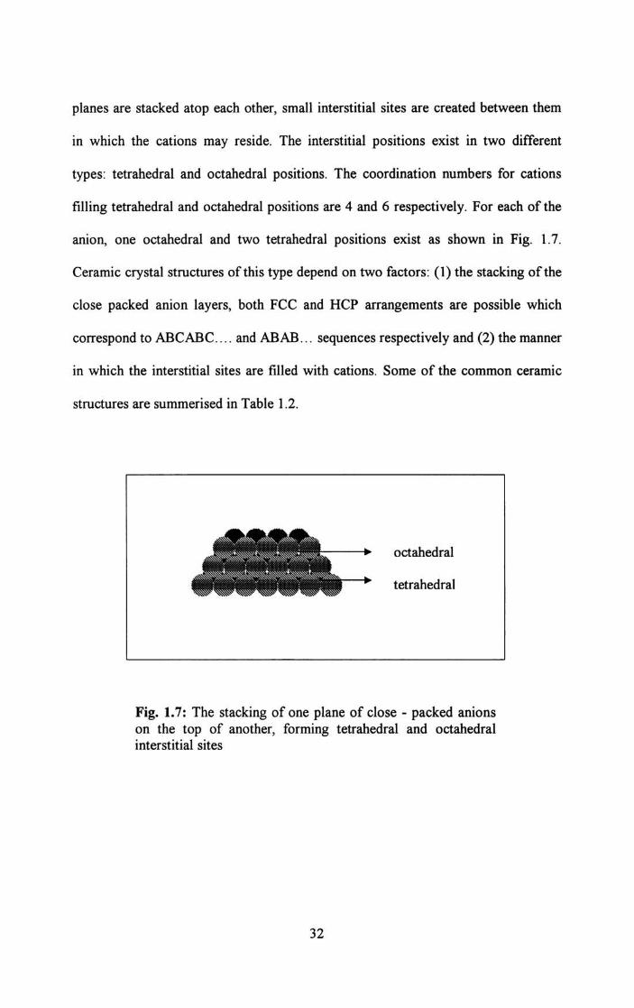
planes are stacked atop each other, small interstitial sites are created between them
in which the cations may reside. The interstitial positions exist in two different
types: tetrahedral and octahedral positions. The coordination numbers for cations
filling tetrahedral and octahedral positions are 4 and 6 respectively. For each of the
anion, one octahedral and two tetrahedral positions exist as shown in Fig. l.7.
Ceramic crystal structures of this type depend on two factors: (1) the stacking of the
close packed anion layers, both FCC and RCP arrangements are possible which
correspond to ABCABC .... and ABAB ... sequences respectively and (2) the manner
in which the interstitial sites are filled with cations. Some of the common ceramic
structures are summerised in Table 1.2.
octahedral
tetrahedral
Fig. 1.7: The stacking of one plane of close - packed anions on the top of another, forming tetrahedral and octahedral interstitial sites
32

Table 1.2: Summary of some common ceramic structures
Coordination Numbers
Structure Structure Anion Cation Anion Examples
Name Type Packing
Rock Salt AX FCC 6 6 NaCI,
(Sodium MgO, FeO
Chloride)
Cesium AX Simple 8 8 CsCI
Chloride Cubic
Zinc blende AX FCC 4 4 ZnS, SiC
(sphalerite)
Flourite AX2 Simple 8 4 CaF2, U02,
Cubic Th02
Perovskite ABX3 FCC 12(A) 6 BaTi03,
6(B) SrZr03.
SrSn03
Spinel AB2Xt FCC 4(A) 4 MgAh0 4,
6(B) FeAh04
33

1.9: Applications of Ceramics
Ceramics are vital for a whole spectrum of applications in areas such as
electronics, communication, medical electronics, environmental engineering
research etc. There are ceramics used as capacitor dielectrics, piezoelectric and
ferroelectric ceramics, ceramic substrate materials, ferroelectric films,
superconductors, NTC and varistors, microwave dielectrics, ferrites and pyroelectric
ceramics. They form the basis of thermal imaging systems, gas sensors, circuit
protection devices for computers, precision control devices in cameras and
automobile suspension systems.
With the technological advances in using dielectric ceramics as microwave
resonators, the progress in microwave telecommunication and satellite broadcasting
has risen rapidly [68-75]. In microwave applications, dielectric resonators are used
to manufacture microwave integrated circuits, pass-band filters, oscillators etc. High
quality dielectric ceramics with high dielectric constant, low dielectric loss and low
temperature coefficient of resonant frequency are extensively used in mobile
communications for the purpose of miniaturization of dimensions of resonator. By
the use of the new generation of ceramic resonators, the filter/combiner units of
cellular base stations processes the messages and send them out again. Today, the
ceramic resonators look a bit like a do-nut in shape, about 5-10 cm in diameter,
depending on the working frequency. Much smaller filters are used in handsets [76].
Resonant frequency of a band-pass filter may be adjusted by using a tuning metallic
element. Dielectric ceramic monoblock microwave band pass filters are compact,
high Q, surface mountable filters with excellent temperature and time stability.
34

Dielectric ceramic resonators are also used for impedance converters, discriminators
and matching circuits. Combiners are used to transmit multiple frequencies on a
single antenna [77].
Coaxial resonators made with modem, high performance ceramic dielectric
materials are very useful as compact frequency standards and distributed inductive
or capacitive circuit elements. The high Q obtained in the UHF and microwave
frequency range makes resonators ideal for many applications. When cost, size and
stability are important, these resonators are the best choice. High dielectric ceramic
materials assure antennas with compact - small size, wide band and high gain. Low
loss and high gain antenna switch modules suitable for SMD mounting in portable
wireless designs can be constructed using ceramic materials. Ceramic components
help to reduce the near field of the antenna, which in turn reduces the specific
absorption rate (SAR) [78]. The main applications [77] of microwave dielectric
resonators are,
(i) Low Noise Block Converters (LNB) for Digital Broadcasting Systems.
(ii) Microwave sources
(iii) Microwave filters and multiplexers
(iv) Security systems, detectors
(v) Auto Cruise Control (ACC) radar systems
(vi) Wireless communication equipments, cellular base stations
(vii) Satellite multiplexing filter devices
(viii) High stability DROs ( Dielectric Resonator Oscillators)
(ix) Microwave duplexers
(x) Radio links
35

(xi) Wideband networks LMDS, MVDS
(xii) GSM
(xiii) PCN/PCS
(xiv) GPS (Global Positioning Systems) antennas
Several industrial components like high vibration high power ultrasonic
transducers and sensors with excellent electro-acoustic efficiency, electronic igniter
having high energy output and voltage with low power consumption. Such growing
importance of ceramic dielectrics has led to great advances in material research and
development also.
1.9.1: Ceramics as substrate materials
Dielectric ceramics are electrical insulators with dielectric strength, dielectric
constant and loss tangent values tailored for specific device or circuit applications
[79]. In capacitor applications, ceramics with a high dielectric constant are used to
increase the charge that can be stored. In microelectronic circuits, low dielectric
constant materials are sought to reduce inductive cross talk and noise generation in
the circuit. In high voltage insulator applications, high electrical resistivity (ohm
cm) and high dielectric stregth (kV per meter) are required.
Ceramic compositions in the system BaO-TiOr RE02 (RE - rare earth
elements) are extensively used in the manufacture of electronic components. These
compositions have high relative permitivity or dielectric constant, which are useful
at high frequencies. Compositions based on BaTi03 are used in the preparation of
PTC resistors and high dielectric contact capacitors. On the other hand, Ti02-rich
compositions may be used for the preparation of dielectrics with low temperature
coefficient of capacitance over a wide range of temperatures and with low dielectric
36
loss. Such materials are regarded particularly suitable for manufacture of multilayer
monolithic capacitors.
The recent advance of novel materials and fabrication technologies,
including monolithic microwave integrated circuit (MMIC), micro electro
mechanical systems (MEMs), micromatching, high temperature superconductor
(HTS) and low temperature co-frred ceramics (LTCC) have stimulated the rapid
development of new microstrip and other filters. L TCC stands for a ceramic
substrate system, which is applied in electronic circuits as cost-effective and
competitive substrate technology with nearly arbitrary number oflayers [80]. Printed
gold and silver conductors or alloys with platinum or palladium will be used in
general. Copper conductors are available too. In today's mobile phones, the power
amplifier and also more often the duplexers are made of L TCC. The power amplifier
exhibits the advantages that L TCC has a better thermal conductivity and that L TCC
is suitable for high integration of passive components. Additionally, the high volume
production costs for such small modules are very low. Each layer can be
manufactured and inspected in parallel before the substrate stack is laminated.
1.10: Outline of work presented in this thesis
In this thesis, the results of our work on the structural and elastic properties
of some selected dielectric ceramics are reported. The experimental techniques we
have used are described in detail in Chapter 2. The subsequent chapters describe the
work done on various materials, results obtained and discussion of results in each
case. The samples selected for investigation are Cas-xZnxNb2 Ti012,
Cas-xMgxNb2Ti012 o( and Barium Samarium Titanate (BST) added with different
37

glasses. The variation of the properties of BST added with different glasses is
studied. Also the variation of properties with increasing wt % of glass is studied and
reported. The different glasses selected for addition are MgO-Ah03 -Si02, ZnO
B203, B203 - Si02, PbO- B203 - Si02, ZnO- B203 - Si02, MgO-B203 - Si02, ZnO
B20 3, Ah03 -Si02, Ah03 -B203 -Si02, BaO-B20 3 -Si02 (30:60:10) and BaO-B203-
Si02 (30:40:30).
The samples are prepared using the standard solid-state ceramic preparation
method. To study the elastic properties, we have measured the longitudinal as well
as the transverse velocities of ultrasonic waves propagating through the sample. The
well-established ultrasonic pulse echo overlap technique has been used to measure
ultrasonic velocities accurately. Details of the measurement technique used are given
in Chapter 2.
38

References
1. S. R. Ovshinsky and H. Fritzsche, IEEE Trans. Electron Devices Ed. 20
(1973) 91
2. 1. M. Ziman, Models of Disorder, Cambridge University Press, ix(1979)
3. R. C. Zeller, R. O. Pohl, Phy. Rev. B4, (1971) 2029
4. W.Heinicke, G. Winterling and K. Dransfeld, J. Acoust. Soc. Am. 49 (1971)
954
5. S. R. Ovshinsky and D. Adler, Contemp. Phys. 19 (1978) 109
6. P. W. Anderson, Phys. Rev. Lett. 34 (1973) 953
7. A. Bienenstock, F. Betts and S. R. Ovshinsky, J. Noncryst. Solids. 2 (1970)
347
8. R. A. Flasck, M. lzu, K. Sapru, T. Anderson, Proc. 7th Intl. Con/. on
Amorph. and Liquid Semiconductors, Edinburgh, Scotland, (1977) 524
9. S. R. Ovshinsky, J. Noncryst. Solids 32 (1979) 179
10. W. H. Zachariasen, J. Am. Chem. Soc. 54 (1932) 3841
11. See, H. Koizumi and T. Ninomiya, J. Phys. Soc. Japan 44 (1978) 898
12. S. R. Herd and P. Chaaudhuri, Phys. Status Solidi A 26 (1974) 627
13. D. E. Sayer, E. A. Stem and F. W. Lytle, Phy. Rev. Lett. 35 (1974) 584
14. N. H. Ritland, J. Am. Ceram. Soc. 37 (1954) 370
15. C. Kittel, Introduction to Solid State Physics, 4th ed. Wiley, New York
(1971)
16. R. 1. Bell, P. Dean, Phi!. Mag. 25 (1972) 1381
17. S. R. Ovshinsky, Phys. Rev. Lett. 36 (1976) 1469
39

18. P. W. Anderson, B. I. Halperin and C. M. Vanna, Phi/os. Mag. 25 (1972) 1
19. W. A. Phillips, J. Low Temp. Phy. 7 (1972) 351
20. H. P. Baltes, Solid State Commun. 13 (1973) 225
21. S. R. Ovshinsky, Proc. 4th Intl. Congress for Reprography and Information,
Hanover, Gennany (1975) 109
22. P. H. Klose and S. R. Ovshinsky, J. Noncryst. Solids, 8-10 (1972) 892
23. A. E. H. Love, Treatise on Mathematical Theory of Elasticity, Cambridge U.
K. (1927)
24. Julian Maynard, Physics Today, Jan (1996) 26
25. B. A. Auld, Acoustic Fields and Waves in Solids, Vol 1, John wiley and
Sons, New York (1973)
26. R. Truell, C. Elbaum, B. B. Chick, Ultrasonic Methods in Solid State
Physics, Academic Press, New York (1973)
27. E. Schreiber, O. L. Anderson, N. Soga, Elastic constants and thier
measurements, Mc. Graw Hill, New York (1973)
28. H. J. McSkimin, Physical Acoustics, VoU, Part a, ed. W. P. Mason,
Academic Press, New York (1964)
29. F. I. Fedorov, Theory of Elastic Waves in Crystals, Plenum Press, New York
(1968)
30. W. P. Mason, Physical Acoustics and the Properties of Solids, D. Van
Nostrand Company, Inc. Princeton, New Jersey (1958)
31. B. Golding, W. H. Haemmerk, L.F. Schneemeyer and J. V. Waszezak, IEEE
1988 Ultrasonic Symposium (IEEE, Piscataway, 1988) 1079
40

32. A. Migliori, 1. L. Sarrao, William, M.\ Visscher, T. M. Bell, Physica B 1-24
(1993) 183
33. D. S. Mathur, Elements of Properties of Matter, Shyamlal Charitable Trust,
Ram Nagar, New Delhi (1978)
34. Brijlal and N. Subrahmanyam, Properties of Matter, Eurasia Publishing
House Pvt. Ltd., New Delhi (1987)
35. H. 1. Stokes, J. Sci. Instrum. 37 (1960) 255
36. G. S. Radley and P. 1. Banks, J. Phys. E: Sci. Instrum. 14 (1981) 546
37. Henry R. Clauser, Industrial and Engineering Materials, McGraw Hill, Inc.
Japan (1975)
38. The American Ceramic Society About Ceramics. Htm 11118/89.
39. Sheela K. Ramasesha, Science and Technology of Ceramics, Resonance,
Aug (1999) 16
40. P. Griel, E. Vogli, T. Fey, A. Bezold, N. Popovska, H. Gerhard and H.
Sieber, J. Euro. Ceram. Soc. 22 (2002) 2697
41. K. Suzuki and M. Sasaki, J. Euro. Ceram. Soc. 2S (2005) 1611
42. 1. Ihle, M. Herrmann and 1. Adler, J. Euro. Ceram. Soc. 2S (2005) 987
43. P. Gonzalez, 1. Serra, S. Liste, S. Chiussi, B. Leon, M. Perez - Amor, 1.
Martinez - Femadez and F. M. Varela - Feria, Biomaterials, 24 (2003) 4827
44. M. Singh and 1. A. Salem, J. Euro. Ceram. Soc. 22 (2002) 2709
45. W. Li, Z. Liu, M. Gu and Y, Jin, Ceram. Internat. 31 (2005) 159
46. H. 1. Choi and Y. W. Kim, J. Euro. Ceram. Soc. 24 (2004) 3795
47. C. R. Rambo, 1. Cao. O. Rusina and Sieber, Carbon, 43 (2005) 1174
48. http:/www.issp.ac.ru/lpcbc/DANDP/MgB2_adv.html
41

49. http://industrial-ceramics.globalspec.comlIndustrial
Directory/zirconium_boride
50. J. M. Mota, M. A. Martinez, F. Velasco and A. J. Criado, Ceram. Internat.
30 (2004) 301
51. S. Sen, Surface Coatings Technology, 190 (2005) 1
52. Y. Iwamoto, H. Nomura and K. Uematsua, J. Mater. Res. 9 No. 5 (1996)
1208
53. M. Amaral, F. Mohasseb, F. 1. Oliveira, F. Benedic, R. F. Silva and A.
Gicquel, Thin Solid Films, 482 (2005) 232
54. F. Zhou, 1. Pan and K. Chen, Mat. Lett. 58 (2004) 1383
55. M. Hirota, M. C Valecillos, M. E. Brito, K. Hirao and M. Toriyama, J. Euro.
Ceram. Soc. 24 (2004) 3337
56. A. Neumann, T. Reske, M. Held, K. Jahnke, C. Ragoss and H. R. Maier, J
Mater Sci Mater Med. 15(10) (2004) 1135
57. A. Ziegler, 1. C. Idrobo, M. K. Cinibulk, C. Kisielowski, N. D. Browning
and R. O. Ritchie, Sci., 306 (2004) 1768
58. Y. Lin, X. S. Ning, H. Zhou, K. Chen, R. Peng and W. Xu, Mat. Lett. 57
(2002) 15
59.1. F. Yang, Z. Y. Deng and T. Ohji, J. Euro. Ceram. Soc. 23 (2003) 371
60.1. H. Ting, S. H. Shiau, Y. 1. Ch en, F. M. Pan, H. Wong, G. M. Pu and C. Y.
Kung, Thin Solid Films, 468(2004) 1
61. C. 1. Rawn, 1. H. Schneibel and C. L Fu, Acta Materialia, 52 (2005) 3843
62. G. S. Brady, Materials Handbook, 10th ed., Mcgraw Hill, Inc., New York
63.1. F. Scott, Mat. Sci. and Eng. B 120, issues 1-3, July (2005) 6
42

64. R. D. Richtmyer, J. Appl. Phys. 10 (1939) 389
65. D. Kajfez and P. Guillon, Dielectric Resonators, Artech House,
Massachussettes (1986)
66. William D. Callister, Jr, Materials Sdence and Engineering: An
Introduction, John Wiley & Sons, Inc. Sixth Edition, (2003)
67. M. W. Barsoum, Fundamentals of Ceramics, McGraw- Hill, New York,
(1997)
68. D. Kolar, Z. Stadler, S. Gaberseek and D. Suvorov, Ber. dl. Keram. Ges. 55
(1978) 346
69. H. M. o. Bryan, J, Thomson and 1. K. Plourde, Ber. dt. Keram. Ges. 55
(1978) 348
70. H. Oshato, T.Ohhashi, S. Nishigaki, J. Appl. Phys.32. (1993) 4323
71. I. Laffez, G. Desgardin, B. Raveau, J. Mat. Sd. 30 (1992) 267
72. Zhai Jiwei, Yao xi, Cheng Xiaogang, J. Mat. Sd. 37 (2002) 3739
73. S. Solomon, N. Santha, N. Jawahar, H. Sreemoolanadhan, M. T. Sebastian
and P. Mohanan, J. Mat. Sd: Materials in Electronics 11 (2000) 595
74. X. M. Chen, N. Qui and Y. Li, J. Electroceram. 9 (2002) 31
75. Chang Chung Lee, Jpn. J. Appl. Phys. 37 (1998) 6048
7 6. http://www2.umist.ac.uklmateriallresearchlmicrowave/tutorial.htm
77. http://www.soquelec.comlfilters.asp
78. http://www.morganadvancedceramics.comlcase_studies/saranteI2.htm
79. http:/ /materials.globalspec.com/LearnMorelMaterials_ Chemicals_Adhesives
/Ceramics_Glass_MaterialslElectroceramicslDielectric_Ceramics_Substrates
43

80. R. Kulke, LTCC - Multilayer Ceramic for Wireless and Sensor Applications,
http://www.ltcc.de
44


![MODELLING GROUND FOUNDATION INTERACTIONSraiith.iith.ac.in/2780/1/MGFI.pdf · features of continuous elastic solids (Kerr [6], 1964; Hetenyi ... elastic beams, or elastic layers capable](https://static.fdocuments.net/doc/165x107/5b49d2347f8b9aa82c8bade8/modelling-ground-foundation-features-of-continuous-elastic-solids-kerr-6.jpg)