
Presentazione di Paolo D'Ermo - WEC Italia - WEC Energy Scenarios to 2050

RETAINING WALL INTRODUCTION
1
INTRODUCTION
A retaining wall is a structure built for the purpose of holding back
or retaining or providing one-sided lateral confinement of soil or other
loose material. The loose material being retained pushes against the wall,
tending to overturn and slide it. Retaining walls are used in many design
situations where there are abrupt changes in the ground slope. Perhaps
the most obvious examples to the reader occur along highway or railroad
cuts and fills. Often, retaining walls are used in these locations to reduce
the quantities of cut and fill as well as to reduce the right-of-way width
required if the soils were allowed to assume their natural slopes. Retaining
walls are used in many other locations as well, such as for bridge
abutments, basement walls, and culverts.
2

INTRODUCTION
Several different types of retaining walls will be discussed, but
whichever type is used, there will be three forces involved that must be
brought into equilibrium:
(1) The gravity loads of the concrete wall and any soil on top of the
footing (the so-called developed weight),
(2) The lateral pressure from the soil, and
(3) The bearing resistance of the soil. In addition, the stresses within
the structure have to be within permissible values, and the loads
must be supported in a manner such that undue settlements do
not occur.
3
TYPES OF RETAINING WALLS
4

TYPES OF RETAINING WALLS
Retaining walls are generally classed as being gravity or cantilever types, with several variations possible. These are described in the slides to follow.
The gravity retaining wall, is used for walls of up to about 10 to 12 ft in height. It is usually constructed with plain concrete and depends completely on its own weight for stability against sliding and overturning. It is usually so massive that it is unreinforced. Tensile stresses calculated by the working-stress method are usually kept below Gravity walls may also be constructed with stone or block masonry.
Semi-gravity retaining walls, fall between the gravity and cantilever types. They depend on their own weights plus the weight of some soil behind the wall to provide stability. Semi-gravity walls are used for approximately the same range of heights as the gravity walls and usually have some light reinforcement.
5

TYPES OF RETAINING WALLS
6

TYPES OF RETAINING WALLS
The cantilever retaining wall or one of its variations is the most
common type of retaining wall. Such walls are generally used for heights
from about 10 to 25 ft. In discussing retaining walls, the vertical wall is
referred to as the stem. The outside part of the footing that is pressed
down into the soil is called the toe, while the part that tends to be lifted is
called the heel. The concrete and its reinforcing are so arranged that part
of the material behind the wall is used along with the concrete weight to
produce the necessary resisting moment against overturning. This resisting
moment is generally referred to as the righting moment.
7

TYPES OF RETAINING WALLS
When it is necessary to construct retaining walls of greater
heights than approximately 20 to 25 ft, the bending moments at the
junction of the stem and footing become so large that the designer will,
from economic necessity, have to consider other types of walls to handle
the moments. This can be done by introducing vertical cross walls on the
front or back of the stem. If the cross walls are behind the stem (that is,
inside the soil) and not visible, the retaining walls are called counterfort
walls. Should the cross walls be visible (that is, on the toe side), the walls
are called buttress walls. The stems for these walls are continuous
members supported at intervals by the buttresses or counterforts.
Counterforts or buttresses are usually spaced at distances approximately
equal to one-half (or a little more) of the retaining wall heights.
8

TYPES OF RETAINING WALLS
9

TYPES OF RETAINING WALLS
The counterfort type is more commonly used because it is
normally thought to be more attractive as the cross walls or counterforts
are not visible. Not only are the buttresses visible on the toe side, but their
protrusion on the outside or toe side of the wall will use up valuable space.
Nevertheless, buttresses are somewhat more efficient than counterforts
because they consist of concrete that is put in compression by the
overturning moments, whereas the counterforts are concrete members
used in a tension situation and they need to be tied to the wall with
stirrups. Occasionally, high walls are designed with both buttresses and
counterforts.
10

TYPES OF RETAINING WALLS
When a retaining wall is placed at a property boundary or next to
an existing building, it may be necessary to use a wall without a toe, or
without a heel. Another type of retaining wall very often encountered is
the bridge abutment. Abutments may very well have wing wall extensions
on the sides to retain the soil in the approach area. The abutment, in
addition to other loads, will have to support the end reactions from the
bridge.
11

TYPES OF RETAINING WALLS
12

TYPES OF RETAINING WALLS
The use of precast retaining walls is becoming more common. The
walls are built with some type of precast units, and the footings are
probably poured in place. The results are very attractive, and the units are
high-quality concrete members made under “plant controlled” conditions.
Less site preparation is required and the erection of the walls is much
quicker than cast-in-place ones. The precast units can later be
disassembled and the units used again. Other types of precast retaining
walls consist of walls or sheeting actually driven into the ground before
excavation. Also showing promise are the gabions or wire baskets of stone
used in conjunction with geotextile reinforced embankments.
13

DRAINAGE One of the most important items in designing and constructing
successful retaining walls is the prevention of water accumulation behind the
walls. If water is allowed to build up there, the result can be great lateral
water pressure against the wall and perhaps an even worse situation in cold
climates due to frost action.
The best possible backfill for a retaining wall is a well-drained and
cohesion less soil. Furthermore, this is the condition for which the designer
normally plans and designs. In addition to a granular backfill material, weep
holes of 4 in. or more in diameter (the large sizes are used for easy cleaning)
are placed in the walls approximately 5 to 10 ft on center, horizontally and
vertically. If the backfill consists of a coarse sand, it is desirable to put a few
shovels of pea gravel around the weep holes to try to prevent the sand from
stopping up the holes. 14
DRAINAGE Weep holes have the disadvantages that the water draining
through the wall is somewhat unsightly and also may cause a softening of
the soil in the area of the highest soil pressure (under the footing toe). A
better method includes the use of a 6- or 8-in. perforated pipe in a bed of
gravel running along the base of the wall. Unfortunately, both weep holes
and drainage pipes can become clogged, with the result that increased
water pressure can occur.
The drainage methods described in the preceding paragraphs are
also quite effective for reducing frost action in colder areas. Frost action
can cause very large movements of walls, not just in terms of inches but
perhaps even in terms of a foot or two, and over a period of time can lead
to failures. 15

DRAINAGE
16

FAILURES OF RETAINING WALLS
The number of failures or partial failures of retaining walls is
rather alarming. The truth of the matter is that if large safety factors were
not used, the situation would be even more severe. One reason for the
large number of failures is the fact that designs are so often based on
methods that are suitable only for certain special situations. For instance,
if a wall that has a saturated clay behind it (never a good idea) is designed
by a method that is suitable for a dry granular material, future trouble will
be the result.
17
LATERAL PRESSURES ON RETAINING WALLS
The actual pressures that occur behind retaining walls are quite
difficult to estimate because of the large number of variables present.
These include the kinds of backfill materials and their compactions and
moisture contents, the types of materials beneath the footings, the
presence or absence of surcharge, and other items. As a result, the
detailed estimation of the lateral forces applied to various retaining walls is
clearly a problem in theoretical soil mechanics. For this reason the
discussion to follow is limited to a rather narrow range of cases.
If a retaining wall is constructed against a solid rock face, there
will be no pressure applied to the wall by the rock. But if the wall is built
to retain a body of water, hydrostatic pressure will be applied to the wall.
18

LATERAL PRESSURES ON RETAINING WALLS
At any point the pressure (p) will equal wh, where w is the unit
weight of the water and h is the vertical distance from the surface of the
water to the point in question.
If a wall is built to retain a soil, the soil’s behavior will generally
be somewhere between that of rock and water (but as we will learn, the
pressure caused by some soils is much higher than that caused by water).
The pressure exerted against the wall will increase, as did the water
pressure, with depth but usually not as rapidly. This pressure at any depth
can be estimated with the following expression:
19
LATERAL PRESSURES ON RETAINING WALLS
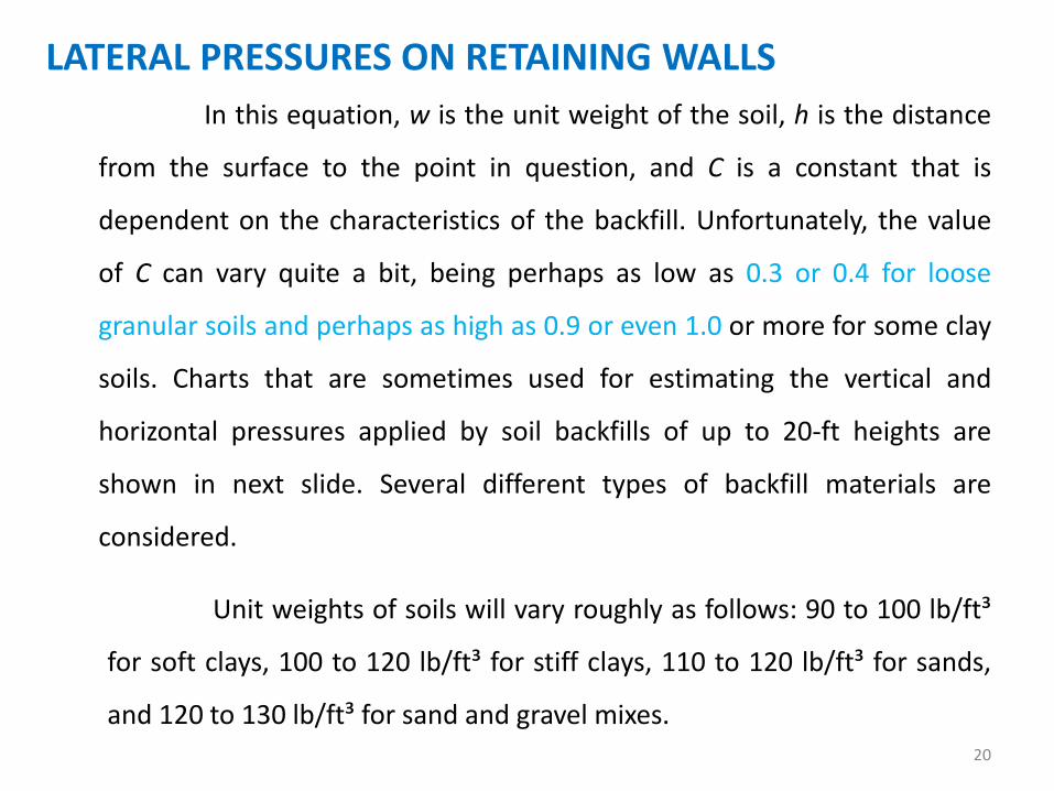
In this equation, w is the unit weight of the soil, h is the distance
from the surface to the point in question, and C is a constant that is
dependent on the characteristics of the backfill. Unfortunately, the value
of C can vary quite a bit, being perhaps as low as 0.3 or 0.4 for loose
granular soils and perhaps as high as 0.9 or even 1.0 or more for some clay
soils. Charts that are sometimes used for estimating the vertical and
horizontal pressures applied by soil backfills of up to 20-ft heights are
shown in next slide. Several different types of backfill materials are
considered.
Unit weights of soils will vary roughly as follows: 90 to 100 lb/ft³
for soft clays, 100 to 120 lb/ft³ for stiff clays, 110 to 120 lb/ft³ for sands,
and 120 to 130 lb/ft³ for sand and gravel mixes. 20

LATERAL PRESSURES ON RETAINING WALLS
21

LATERAL PRESSURES ON RETAINING WALLS
If you carefully study the second chart of last slide, you will
probably be amazed to see how high lateral pressures can be, particularly
for clays and silts. As an illustration, a 1 ft-wide vertical strip is considered
for a 15-ft-high retaining wall backfilled with soil number (4) with an
assumed δ of 10˚ (6 : 1 slope). The total estimated horizontal pressure on
the strip is
22
LATERAL PRESSURES ON RETAINING WALLS
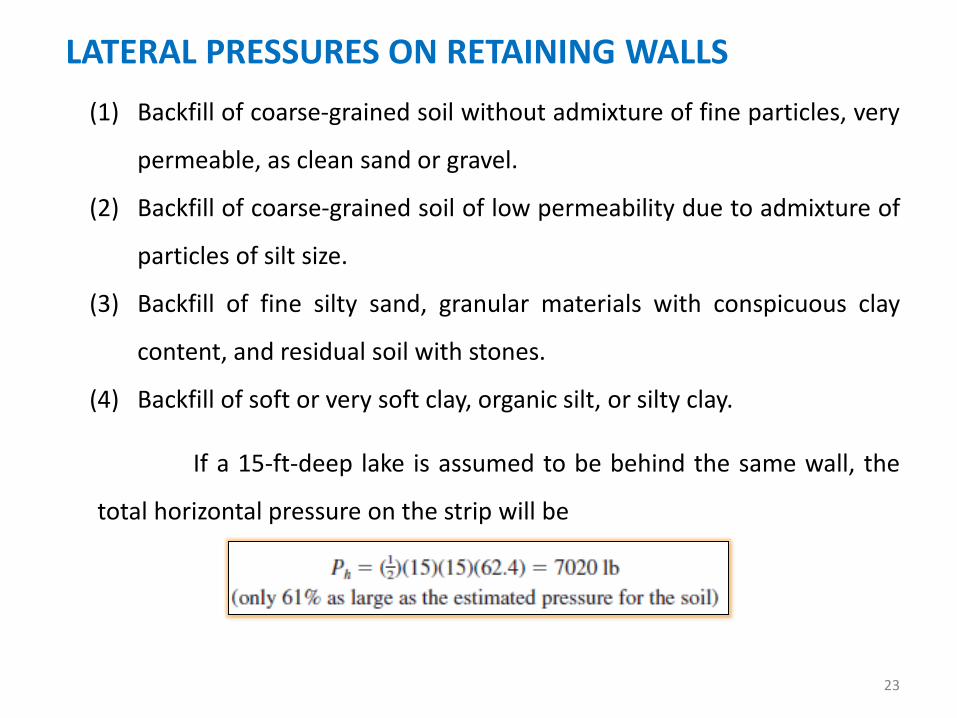
(1) Backfill of coarse-grained soil without admixture of fine particles, very
permeable, as clean sand or gravel.
(2) Backfill of coarse-grained soil of low permeability due to admixture of
particles of silt size.
(3) Backfill of fine silty sand, granular materials with conspicuous clay
content, and residual soil with stones.
(4) Backfill of soft or very soft clay, organic silt, or silty clay.
If a 15-ft-deep lake is assumed to be behind the same wall, the
total horizontal pressure on the strip will be
23

LATERAL PRESSURES ON RETAINING WALLS
For this discussion, a retaining wall supporting a sloping earth fill
is shown below. Part of the earth behind the wall (shown by the hatched
area) tends to slide along a curved surface (represented by the dashed
line) and push against the retaining wall. The tendency of this soil to slide
is resisted by friction along the soil underneath (called internal friction)
and by friction along the vertical face of the retaining wall.
24

LATERAL PRESSURES ON RETAINING WALLS
Internal friction is greater for a cohesive soil than for a non
cohesive one, but the wetter such a soil becomes, the smaller will be its
cohesiveness and thus the flatter the plane of rupture. The flatter the
plane of rupture, the greater is the volume of earth tending to slide and
push against the wall. Once again it can be seen that good drainage is of
the utmost importance. Usually the designer assumes that a cohesion less
granular backfill will be placed behind the walls.
Due to lateral pressure, the usual retaining wall will give or
deflect a little because it is constructed of elastic materials. Furthermore,
unless the wall rests on a rock foundation, it will tilt or lean a small
distance away from the soil due to the compressible nature of the
supporting soils.
25

LATERAL PRESSURES ON RETAINING WALLS
Under the lateral pressures described, the usual retaining wall will
move a little distance and active soil pressure will develop. Among the
many factors that affect the pressure applied to a particular wall are the
kind of backfill material used, the drainage situation, the level of the water
table, the seasonal conditions such as dry or wet or frozen, the presence of
trucks or other equipment on the backfill, and so on.
For these reasons, retaining walls are frequently constructed
with a slight batter, or inclination, toward the backfill so that the
deformations described are not obvious to the passerby.
26

LATERAL PRESSURES ON RETAINING WALLS
For design purposes it is usually satisfactory to assume that the
active pressure varies linearly with the depth of the backfill. In other
words, it is just as though (so far as lateral pressure is concerned) there is a
liquid of some weight behind the wall that can vary from considerably less
than the weight of water to considerably more. The chart shown earlier
shows this large variation in possible lateral pressures. The assumed lateral
pressures are often referred to as equivalent fluid pressures. Values from
30 to 50 pcf are normally assumed but may be much too low for clay and
silt materials.
If the wall moves away from the backfill and against the soil at the
toe, a passive soil pressure will be the result. Passive pressure, which is
also assumed to vary linearly with depth.
27
LATERAL PRESSURES ON RETAINING WALLS
The inclusion or non-inclusion of passive pressure in the design
calculations is a matter of judgment on the designer’s part. For effective
passive pressure to be developed at the toe, the toe concrete must be
placed against undisturbed earth without the use of vertical forms. Even if
this procedure is followed, the designer will probably reduce the height of
the undisturbed soil (h’ in figure) used in the calculations to account for
some disturbance of the earth during construction operations.
As long as the backfills are granular, no cohesive, and dry, the
assumption of an equivalent liquid pressure is fairly satisfactory. Formulas
based on an assumption of dry sand or gravel backfills are not satisfactory
for soft clays or saturated sands. Actually, clays should not be used for
backfills because their shear characteristics change easily and they may
tend to creep against the wall, increasing pressures as time goes by. 28

LATERAL PRESSURES ON RETAINING WALLS
29

LATERAL PRESSURES ON RETAINING WALLS
If a linear pressure variation is assumed, the active pressure at
any depth can be determined as
In these expressions, Ca and Cp are the approximate coefficients of
active and passive pressures, respectively. These coefficients can be
calculated by theoretical equations such as those of Rankine or Coulomb.
For a granular material, typical values of Ca and Cp are 0.3 and 3.3. The
Rankine equation (published in 1857) neglects the friction of the soil on
the wall, whereas the Coulomb formula (published in 1776) takes it into
consideration. These two equations were developed for cohesion less soils. 30

LATERAL PRESSURES ON RETAINING WALLS
For cohesive soils containing clays and/or silts it is necessary to
use empirical values determined from field measurements.
It has been estimated that the cost of constructing retaining walls
varies directly with the square of their heights. Thus as retaining walls
become higher, the accuracy of the computed lateral pressures becomes
more and more important in providing economical designs. Since the
Coulomb equation does take into account friction on the wall, it is thought
to be the more accurate one and is often used for walls of over 20 ft. The
Rankine equation is commonly used for ordinary retaining walls of 20 ft or
less in height. It is interesting to note that the two methods give identical
results if the friction of the soil on the wall is neglected.
31

LATERAL PRESSURES ON RETAINING WALLS
Just revising Soil Mechanics the Rankine expressions for the active
and passive pressure coefficients are given below. In these expressions δ is
the angle the backfill makes with the horizontal, while φ is the angle of
internal friction of the soil. For well-drained sand or gravel backfills, the
angle of internal friction is often taken as the angle of repose of the slope.
One common slope used is 1½ vertically to horizontally.
32

LATERAL PRESSURES ON RETAINING WALLS
Should the backfill be horizontal—that is, should δ be equal to
zero—the expressions become
One trouble with using these expressions is in the determination
of φ. It can be as small as 0˚ to 10˚ for soft clays and as high as 30˚ or 40˚
for some granular materials. As a result, the values of Ca can vary from
perhaps 0.30 for some granular materials up to about 1.0 for some wet
clays.
Once the values of Ca and Cp are determined, the total horizontal
pressures, Ha and Hp, can be calculated as being equal to the areas of the
respective triangular pressure diagrams. 33

LATERAL PRESSURES ON RETAINING WALLS
34

LATERAL PRESSURES ON RETAINING WALLS
For instance, with reference made to last figure, the value of the
active pressure is
In addition to these lateral pressures applied to the retaining wall,
it is considered necessary to add the effect of frost action at the top of the
stem.
35

FOOTING SOIL PRESSURES
36

FOOTING SOIL PRESSURES
Because of lateral forces, the resultant of the horizontal and
vertical forces R intersects the soil underneath the footing as an eccentric
load, causing greater pressure at the toe. This toe pressure should be less
than the permissible value qa of the particular soil. It is also desirable to
keep the resultant force within the kern or the middle third of the footing
base.
If the resultant force intersects the soil within the middle third of
the footing, the soil pressure at any point can be calculated with the
formula to follow exactly as the stresses are determined in an
eccentrically loaded column.
37

FOOTING SOIL PRESSURES
In this expression, Rv is the vertical component of R or the total
vertical load, e is the eccentricity of the load from the center of the
footing, A is the area of a 1-ft-wide strip of soil of a length equal to the
width of the footing base, and I is the moment of inertia of the same area
about its centroid. This expression is correct only if Rv falls within the kern.
This expression can be reduced to the following expression, in
which L is the width of the footing from heel to toe.
38
FOOTING SOIL PRESSURES
If the resultant force falls outside of the middle third of the
footing, the preceding expressions are not applicable because they
indicate a tensile stress on one side of the footing a stress the soil cannot
supply. Such a situation should not be permitted in a retaining wall and is
not considered further.
The soil pressures computed in this manner are only rough
estimates of the real values and thus should not be valued too highly. The
true pressures are appreciably affected by quite a few items other than
the retaining wall weight. Included are drainage conditions, temperature,
settlement, pore water, and so on.
39

DESIGN OF SEMIGRAVITY RETAINING WALLS As previously mentioned, semi-gravity retaining walls are
designed to resist earth pressure by means of their own weight plus some
developed soil weight. Because they are normally constructed with plain
concrete, stone, or perhaps some other type of masonry, their design is
based on the assumption that only very little tension or none at all can be
permitted in the structure. If the resultant of the earth pressure and the
wall weight (including any developed soil weight) falls within the middle
third of the wall base, tensile stresses will probably be negligible.
A wall size is assumed, safety factors against sliding and
overturning are calculated, the point where the resultant force strikes the
base is determined, and the soil pressures are calculated. It is normally
felt that safety factors against sliding should be at least 1.5 for cohesion
less backfills and 2.0 for cohesive ones. 40

DESIGN OF SEMIGRAVITY RETAINING WALLS Safety factors of 2.0 for overturning are normally specified. A
suitable wall is probably obtained after two or three trial sizes. Example
13.1 illustrates the calculations that need to be made for each trial.
Figure 13.8(a) shows a set of approximate dimensions that are
often used for sizing semi-gravity walls. Dimensions may be assumed to
be approximately equal to the values given and the safety factors against
overturning and sliding computed. If the values are not suitable, the
dimensions are adjusted and the safety factors are recalculated, and so
on. Semi-gravity walls are normally trapezoidal in shape, as shown in
Figure 13.8(a), but sometimes they may have broken backs, as illustrated
in Figure 13.8(b).
41

DESIGN OF SEMIGRAVITY RETAINING WALLS
42

EFFECT OF SURCHARGE
Should there be earth or other loads on the surface of the
backfill, the horizontal pressure applied to the wall will be
increased. If the surcharge is uniform over the sliding area behind
the wall, the resulting pressure is assumed to equal the pressure
that would be caused by an increased backfill height having the
same total weight as the surcharge. It is usually easy to handle this
situation by adding a uniform pressure to the triangular soil
pressure for a wall without surcharge, as shown in the figure.
48

EFFECT OF SURCHARGE
49

EFFECT OF SURCHARGE
If the surcharge does not cover the area entirely behind
the wall, some rather complex soil theories are available to consider
the resulting horizontal pressures developed. As a consequence, the
designer usually uses a rule of thumb to cover the case, a procedure
that works reasonably well. He or she may assume, that surcharge
cannot affect the pressure above the intersection of a 45˚ line from
the edge of the surcharge to the wall. The lateral pressure is
increased, as by a full surcharge, below the intersection point. This
is shown in the right side of the figure.
50

EFFECT OF SURCHARGE
51


![[PPT]Irrigation Engineering CE-404 (3+0) - WEC CIVILIANS - …weccivilians.weebly.com/uploads/2/4/6/2/24623713/... · Web viewInundation canal off-taking from a river is a seasonal](https://static.fdocuments.net/doc/165x107/5aed1ba97f8b9a3669906a72/pptirrigation-engineering-ce-404-30-wec-civilians-viewinundation-canal.jpg)