Chapter 1ptgmedia.pearsoncmg.com/.../activities/keytopics/KeyTopics.pdf · inserts an extra 4-byte...
262
Chapter 1 For example, in Figure 1-2, the single switch creates two VLANs, treating the ports in each VLAN as being completely separate. The switch would never forward a frame sent by Dino (in VLAN 1) over to either Wilma or Betty (in VLAN 2). Fred Dino Betty Wilma Broadcast Domain 2 (VLAN 2) Broadcast Domain 1 (VLAN 1) SW1 Subnet 2 Subnet 1 Figure 1-2 Creating Two Broadcast Domains Using One Switch and VLANs
Transcript of Chapter 1ptgmedia.pearsoncmg.com/.../activities/keytopics/KeyTopics.pdf · inserts an extra 4-byte...

Chapter 1For example, in Figure 1-2, the single switch creates two VLANs, treating the ports in each VLAN as being completely separate. The switch would never forward a frame sent by Dino (in VLAN 1) over to either Wilma or Betty (in VLAN 2).
Fred
Dino
Betty
WilmaBroadcastDomain 2(VLAN 2)
BroadcastDomain 1(VLAN 1)
SW1Subnet 2Subnet 1
Figure 1-2 Creating Two Broadcast Domains Using One Switch and VLANs

2 CCNA Routing and Switching ICND2 200-105 Official Cert Guide
Designing campus LANs to use more VLANs, each with a smaller number of devices, often helps improve the LAN in many ways. For example, a broadcast sent by one host in a VLAN will be received and processed by all the other hosts in the VLAN—but not by hosts in a different VLAN. Limiting the number of hosts that receive a single broadcast frame reduces the number of hosts that waste effort processing unneeded broadcasts. It also reduces security risks, because fewer hosts see frames sent by any one host. These are just a few reasons for separating hosts into different VLANs. The following list summarizes the most common reasons for choosing to create smaller broadcast domains (VLANs):
■ To reduce CPU overhead on each device by reducing the number of devices that receive each broadcast frame
■ To reduce security risks by reducing the number of hosts that receive copies of frames that the switches flood (broadcasts, multicasts, and unknown unicasts)
■ To improve security for hosts that send sensitive data by keeping those hosts on a sepa-rate VLAN
■ To create more flexible designs that group users by department, or by groups that work together, instead of by physical location
■ To solve problems more quickly, because the failure domain for many problems is the same set of devices as those in the same broadcast domain
■ To reduce the workload for the Spanning Tree Protocol (STP) by limiting a VLAN to a single access switch

Key Topics 3
The use of trunking allows switches to pass frames from multiple VLANs over a single physical connection by adding a small header to the Ethernet frame. For example, Figure 1-5 shows PC11 sending a broadcast frame on interface Fa0/1 at Step 1. To flood the frame, switch SW1 needs to forward the broadcast frame to switch SW2. However, SW1 needs to let SW2 know that the frame is part of VLAN 10, so that after the frame is received, SW2 will flood the frame only into VLAN 10, and not into VLAN 20. So, as shown at Step 2, before sending the frame, SW1 adds a VLAN header to the original Ethernet frame, with the VLAN header listing a VLAN ID of 10 in this case.
20 10 20 10 20
VLAN 10
VLAN 20
13
0/1 0/2
G0/2G0/1
0/3 0/4
14
23 24
VLAN 10
VLAN 20
11
0/1
0/3 0/4
21 22
33Ethernet
1Ethernet
2
VLAN 10 EthernetSW1 SW2
Figure 1-5 VLAN Trunking Between Two Switches

4 CCNA Routing and Switching ICND2 200-105 Official Cert Guide
While both ISL and 802.1Q tag each frame with the VLAN ID, the details differ. 802.1Q inserts an extra 4-byte 802.1Q VLAN header into the original frame’s Ethernet header, as shown at the top of Figure 1-6. As for the fields in the 802.1Q header, only the 12-bit VLAN ID field inside the 802.1Q header matters for topics discussed in this book. This 12-bit field supports a theoretical maximum of 212 (4096) VLANs, but in practice it sup-ports a maximum of 4094. (Both 802.1Q and ISL use 12 bits to tag the VLAN ID, with two reserved values [0 and 4095].)
802.1Q
Dest. Address Source Address Type Data FCSTag
Type Priority Flag VLAN ID (12 Bits)
Figure 1-6 802.1Q Trunking

Key Topics 5
Figure 1-9 shows the same design idea as Figure 1-8, with the same packet being sent from Fred to Betty, except now R1 uses VLAN trunking instead of a separate link for each VLAN.
Fred
F0/0
Dino
Betty
WilmaVLAN 20Subnet 20
VLAN 10Subnet 10
SW1
R1
1 2
Figure 1-9 Routing Between Two VLANs Using a Trunk on the Router

6 CCNA Routing and Switching ICND2 200-105 Official Cert Guide
In concept, a Layer 3 switch works a lot like the original two devices on which the Layer 3 switch is based: a Layer 2 LAN switch and a Layer 3 router. In fact, if you take the concepts and packet flow shown in Figure 1-8, with a separate Layer 2 switch and Layer 3 router, and then imagine all those features happening inside one device, you have the general idea of what a Layer 3 switch does. Figure 1-10 shows that exact concept, repeating many details of Figure 1-8, but with an overlay that shows the one Layer 3 switch doing the Layer 2 switch functions and the separate Layer 3 routing function.
Fred
Interface VLAN 10
Interface VLAN 20
Layer 3 Switch
Dino
Betty
Wilma
Layer 2 Switch
Layer 3 Router
(All Functions in Middle Box)VLAN 20Subnet 20
VLAN 10Subnet 10
Figure 1-10 Multilayer Switch: Layer 2 Switching with Layer 3 Routing in One Device

Key Topics 7
DTP can also negotiate whether the two devices on the link agree to trunk at all, as guided by the local switch port’s administrative mode. The administrative mode refers to the con-figuration setting for whether trunking should be used. Each interface also has an opera-tional mode, which refers to what is currently happening on the interface, and might have been chosen by DTP’s negotiation with the other device. Cisco switches use the switchport
mode interface subcommand to define the administrative trunking mode, as listed in Table 1-2.
Table 1-2 Trunking Administrative Mode Options with the switchport mode Command
Command Option Description
access Always act as an access (nontrunk) port
trunk Always act as a trunk port
dynamic desirable Initiates negotiation messages and responds to negotiation messages to dynamically choose whether to start using trunking
dynamic auto Passively waits to receive trunk negotiation messages, at which point the switch will respond and negotiate whether to use trunking

8 CCNA Routing and Switching ICND2 200-105 Official Cert Guide
For the exams, you should be ready to interpret the output of the show interfaces switch-
port command, realize the administrative mode implied by the output, and know whether the link should operationally trunk based on those settings. Table 1-3 lists the combinations of the trunking administrative modes and the expected operational mode (trunk or access) resulting from the configured settings. The table lists the administrative mode used on one end of the link on the left, and the administrative mode on the switch on the other end of the link across the top of the table.
Table 1-3 Expected Trunking Operational Mode Based on the Configured Administrative
Modes
Administrative Mode Access Dynamic Auto Trunk Dynamic Desirable
access Access Access Do Not Use1 Access
dynamic auto Access Access Trunk Trunk
trunk Do Not Use1 Trunk Trunk Trunk
dynamic desirable Access Trunk Trunk Trunk
1 When two switches confi gure a mode of “access” on one end and “trunk” on the other, problems occur. Avoid this combination.

Key Topics 9
Sites that use IP telephony, which includes most every company today, now have two devic-es off each access port. In addition, Cisco best practices for IP telephony design tell us to put the phones in one VLAN, and the PCs in a different VLAN. To make that happen, the switch port acts a little like an access link (for the PC’s traffic), and a little like a trunk (for the phone’s traffic). The configuration defines two VLANs on that port, as follows:
Data VLAN: Same idea and configuration as the access VLAN on an access port, but defined as the VLAN on that link for forwarding the traffic for the device connected to the phone on the desk (typically the user’s PC).
Voice VLAN: The VLAN defined on the link for forwarding the phone’s traffic. Traffic in this VLAN is typically tagged with an 802.1Q header.

10 CCNA Routing and Switching ICND2 200-105 Official Cert Guide
It might seem like this short topic about IP telephony and switch configuration includes a lot of small twists and turns and trivia, and it does. The most important items to remember are as follow:
■ Configure these ports like a normal access port to begin: Configure it as a static access port and assign it an access VLAN.
■ Add one more command to define the voice VLAN (switchport voice vlan vlan-id).
■ Look for the mention of the voice VLAN ID, but no other new facts, in the output of the show interfaces type number switchport command.
■ Look for both the voice and data (access) VLAN IDs in the output of the show
interfaces type number trunk command.
■ Do not expect to see the port listed in the list of operational trunks as listed by the show
interfaces trunk command.

Key Topics 11
Chapter 2Table 2-2 summarizes the main three classes of problems that occur when STP is not used in a LAN that has redundancy.
Table 2-2 Three Classes of Problems Caused by Not Using STP in Redundant LANs
Problem Description
Broadcast storms The forwarding of a frame repeatedly on the same links, consuming significant parts of the links’ capacities
MAC table instability The continual updating of a switch’s MAC address table with incorrect entries, in reaction to looping frames, resulting in frames being sent to the wrong locations
Multiple frame transmission
A side effect of looping frames in which multiple copies of one frame are delivered to the intended host, confusing the host

12 CCNA Routing and Switching ICND2 200-105 Official Cert Guide
All other interfaces are placed in blocking state. Table 2-3 summarizes the reasons STP places a port in forwarding or blocking state.
Table 2-3 STP: Reasons for Forwarding or Blocking
Characterization of Port STP State Description
All the root switch’s ports Forwarding The root switch is always the designated switch on all connected segments.
Each nonroot switch’s root port
Forwarding The port through which the switch has the least cost to reach the root switch (lowest root cost).
Each LAN’s designated port
Forwarding The switch forwarding the Hello on to the segment, with the lowest root cost, is the designated switch for that segment.
All other working ports Blocking The port is not used for forwarding user frames, nor are any frames received on these interfaces considered for forwarding.

Key Topics 13
STP defines messages called bridge protocol data units (BPDU), which switches use to exchange information with each other. The most common BPDU, called a Hello BPDU, lists many details, including the sending switch’s BID. By listing its own unique BID, switches can tell which switch sent which Hello BPDU. Table 2-4 lists some of the key information in the Hello BPDU.
Table 2-4 Fields in the STP Hello BPDU
Field Description
Root bridge ID The bridge ID of the switch the sender of this Hello currently believes to be the root switch
Sender’s bridge ID The bridge ID of the switch sending this Hello BPDU
Sender’s root cost The STP cost between this switch and the current root
Timer values on the root switch Includes the Hello timer, MaxAge timer, and forward delay timer

14 CCNA Routing and Switching ICND2 200-105 Official Cert Guide
Summarizing, the root election happens through each switch claiming to be root, with the best switch being elected based on the numerically lowest BID. Breaking down the BID into its components, the comparisons can be made as
■ The lowest priority
■ If that ties, the lowest switch MAC address

Key Topics 15
Figure 2-6 shows an example of how switches calculate their best root cost and then choose their root port, using the same topology and STP costs as shown in Figure 2-5. STP on SW3 calculates its cost to reach the root over the two possible paths by adding the advertised cost (in Hello messages) to the interface costs listed in the figure.
Gi0/1
Gi0/1
Gi0/2
Gi0/2 SW2
SW3
Gi0/1Gi0/2
SW1
0 + 4 = 4
0 + 5 = 5 4 + 4 = 8
Cost = 4
Cost = 4
Cost = 5
My Root Cost Out G0/2 is 4
Root Cost out G0/1 is 5Root Cost out G0/2 is 8
Root Cost = 0 Root Cost = 4
Root Cost = 0
Root
Hello
HelloHello
InterfaceInterface
Interface
Figure 2-6 How STP Actually Calculates the Cost from SW3 to the Root

16 CCNA Routing and Switching ICND2 200-105 Official Cert Guide
Port costs also have default values, per port, per VLAN. You can configure these port costs, or you can use the default values. Table 2-6 lists the default port costs suggested by IEEE. IOS on Cisco switches has long used the default settings as defined in the 1998 version of the 802.1D standard. The newer standard, useful when using links faster than 10 Gbps, can be used by adding a single configuration command to each switch (spanning-tree pathcost
method long).
Table 2-6 Default Port Costs According to IEEE
Ethernet Speed IEEE Cost: 1998 (and Before) IEEE Cost: 2004 (and After)
10 Mbps 100 2,000,000
100 Mbps 19 200,000
1 Gbps 4 20,000
10 Gbps 2 2000
100 Gbps N/A 200
1 Tbps N/A 20

Key Topics 17
By forwarding the received (and changed) Hellos out all DPs, all switches continue to receive Hellos every 2 seconds. The following steps summarize the steady-state operation when nothing is currently changing in the STP topology:
Step 1. The root creates and sends a Hello BPDU, with a root cost of 0, out all its working interfaces (those in a forwarding state).
Step 2. The nonroot switches receive the Hello on their root ports. After changing the Hello to list their own BID as the sender’s BID, and listing that switch’s root cost, the switch forwards the Hello out all designated ports.
Step 3. Steps 1 and 2 repeat until something changes.

18 CCNA Routing and Switching ICND2 200-105 Official Cert Guide
For various reasons, the convergence process requires the use of three timers. Note that all switches use the timers as dictated by the root switch, which the root lists in its periodic Hello BPDU messages. Table 2-7 describes the timers.
Table 2-7 STP Timers
Timer Default Value Description
Hello 2 seconds The time period between Hellos created by the root.
MaxAge 10 times Hello How long any switch should wait, after ceasing to hear Hellos, before trying to change the STP topology.
Forward delay
15 seconds Delay that affects the process that occurs when an interface changes from blocking state to forwarding state. A port stays in an interim listening state, and then an interim learning state, for the number of seconds defined by the forward delay timer.

Key Topics 19
When a port that formerly blocked needs to transition to forwarding, the switch first puts the port through two intermediate interface states. These temporary states help prevent temporary loops:
■ Listening: Like the blocking state, the interface does not forward frames. The switch removes old stale (unused) MAC table entries for which no frames are received from each MAC address during this period. These stale MAC table entries could be the cause of the temporary loops.
■ Learning: Interfaces in this state still do not forward frames, but the switch begins to learn the MAC addresses of frames received on the interface.

20 CCNA Routing and Switching ICND2 200-105 Official Cert Guide
Table 2-8 summarizes spanning tree’s various interface states for easier review.
Table 2-8 IEEE 802.1D Spanning-Tree States
State Forwards Data Frames?
Learns MACs Based on Received Frames?
Transitory or Stable State?
Blocking No No Stable
Listening No No Transitory
Learning No Yes Transitory
Forwarding Yes Yes Stable
Disabled No No Stable

Key Topics 21
RSTP (802.1w) works just like STP (the original 802.1D) in several ways:
■ It elects the root switch using the same parameters and tiebreakers.
■ It elects the root port on nonroot switches with the same rules.
■ It elects designated ports on each LAN segment with the same rules.
■ It places each port in either forwarding or blocking state, although RSTP calls the block-ing state the discarding state.

22 CCNA Routing and Switching ICND2 200-105 Official Cert Guide
The best way to get a sense for these mechanisms is to see how the RSTP alternate port and the backup port both work. RSTP uses the term alternate port to refer to a switch’s other ports that could be used as root port if the root port ever fails. The backup port concept provides a backup port on the local switch for a designated port, but only applies to some topologies that frankly do not happen often with a modern network design. However, both are instructive about how RSTP works. Table 2-9 lists these RSTP port roles.
Table 2-9 Port Roles in 802.1w RSTP
Function Port Role
Nonroot switch’s best path to the root Root port
Replaces the root port when the root port fails Alternate port
Switch port designated to forward onto a collision domain Designated port
Replaces a designated port when a designated port fails Backup port
Port that is administratively disabled Disabled port
Key Topics 23
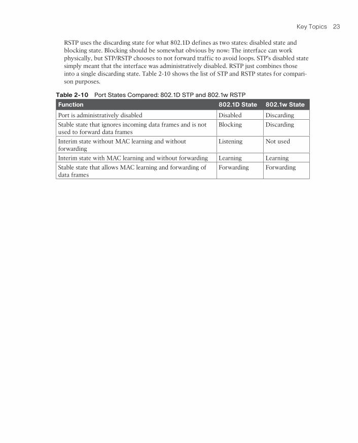
RSTP uses the discarding state for what 802.1D defines as two states: disabled state and blocking state. Blocking should be somewhat obvious by now: The interface can work physically, but STP/RSTP chooses to not forward traffic to avoid loops. STP’s disabled state simply meant that the interface was administratively disabled. RSTP just combines those into a single discarding state. Table 2-10 shows the list of STP and RSTP states for compari-son purposes.
Table 2-10 Port States Compared: 802.1D STP and 802.1w RSTP
Function 802.1D State 802.1w State
Port is administratively disabled Disabled Discarding
Stable state that ignores incoming data frames and is not used to forward data frames
Blocking Discarding
Interim state without MAC learning and without forwarding
Listening Not used
Interim state with MAC learning and without forwarding Learning Learning
Stable state that allows MAC learning and forwarding of data frames
Forwarding Forwarding

24 CCNA Routing and Switching ICND2 200-105 Official Cert Guide
Chapter 3For instance, Figure 3-1 shows a typical LAN design model, with two distribution layer switches (D1 and D2). The design may have dozens of access layer switches that connect to end users; the figure shows just three access switches (A1, A2, and A3). For a variety of rea-sons, most network engineers make the distribution layer switches be the root. For instance, the configuration could make D1 be the root by having a lower priority, with D2 config-ured with the next lower priority, so it becomes root if D1 fails.
10/100/1000
DistributionSwitches
AccessSwitches
D1 D2
A1
10/100/1000
A2
10/100/1000
A3
Best Choices to be Root
Figure 3-1 Typical Configuration Choice: Making Distribution Switch Be Root

Key Topics 25
PVST+ gives engineers a load-balancing tool with STP. By changing some STP configura-tion parameters differently for different VLANs, the engineer could cause switches to pick different RPs and DPs in different VLANs. As a result, some traffic in some VLANs can be forwarded over one trunk, and traffic for other VLANs can be forwarded over a different trunk.
Figure 3-2 shows the basic idea, with SW3 forwarding odd-numbered VLAN traffic over the left trunk (Gi0/1) and even-numbered VLANs over the right trunk (Gi0/2).
Gi0/1
Gi0/1
Gi0/2
Gi0/2SW2
SW3
Gi0/1
Gi0/2SW1
Root
VLAN 1 STP Topology
Gi0/1
Gi0/1
Gi0/2
Gi0/2SW2
SW3
Gi0/1
Gi0/2SW1
Root
VLAN 2 STP Topology
Figure 3-2 Load Balancing with PVST+

26 CCNA Routing and Switching ICND2 200-105 Official Cert Guide
Originally, a switch’s BID was formed by combining the switch’s 2-byte priority and its 6-byte MAC address. Later, the IEEE changed the rules, splitting the original priority field into two separate fields, as shown in Figure 3-3: a 4-bit priority field and a 12-bit subfield called the system ID extension (which represents the VLAN ID).
Priority(0 – 65,535)
System ID(MAC Address)
System ID Extension(Typically Holds VLAN ID)
Priority(Multipleof 4096)
6 Bytes
System ID(MAC Address)
2 Bytes
12 Bits4 Bits
Original FormatBridge ID
System IDExtension(MAC AddressReduction)
6 Bytes
Figure 3-3 STP System ID Extension

Key Topics 27
Table 3-2 summarizes the default settings for both the BID and the port costs and lists the optional configuration commands covered in this chapter.
Table 3-2 STP Defaults and Configuration Options
Setting Default Command(s) to Change Default
BID priority Base: 32,768 spanning-tree vlan vlan-id root {primary | secondary}
spanning-tree vlan vlan-id priority priority
Interface cost 100 for 10 Mbps
19 for 100 Mbps
4 for 1 Gbps
2 for 10 Gbps
spanning-tree vlan vlan-id cost cost
PortFast Not enabled spanning-tree portfast
BPDU Guard Not enabled spanning-tree bpduguard enable

28 CCNA Routing and Switching ICND2 200-105 Official Cert Guide
The spanning-tree vlan vlan-id root primary command tells the switch to set its priority low enough to become root right now. The switch looks at the current root in that VLAN, and at the root’s priority. Then the local switch chooses a priority value that causes the local switch to take over as root.
Remembering that Cisco switches use a default base priority of 32,768, this command chooses the base priority as follows:
■ If the current root has a base priority higher than 24,576, the local switch uses a base pri-ority of 24,576.
■ If the current root’s base priority is 24,576 or lower, the local switch sets its base priority to the highest multiple of 4096 that still results in the local switch becoming root.

Key Topics 29
To configure an EtherChannel manually, follow these steps:
Step 1. Add the channel-group number mode on command in interface configuration mode under each physical interface that should be in the channel to add it to the channel.
Step 2. Use the same number for all commands on the same switch, but the channel-group number on the neighboring switch can differ.

30 CCNA Routing and Switching ICND2 200-105 Official Cert Guide
Cisco Catalyst switches operate in some STP mode as defined by the spanning-tree mode global configuration command. Based on this command’s setting, the switch is using either 802.1D STP or 802.1w RSTP, as noted in Table 3-4.
Table 3-4 Cisco Catalyst STP Configuration Modes
Parameter on spanning-tree mode Command
Uses STP or RSTP?
Protocol Listed in Command Output
Description
pvst STP ieee Default; Per-VLAN Spanning Tree instance
rapid-pvst RSTP rstp Like PVST, but uses RSTP rules instead of STP for each STP instance
mst RSTP mst Creates multiple RSTP instances but does not require one instance per each VLAN

Key Topics 31
Pay close attention to this short description of an oddity about the STP and RSTP output on Catalyst switches! Cisco Catalyst switches often show the alternate and backup ports in output even when using STP and not RSTP. The alternate and backup port concepts are RSTP concepts. The switches only converge faster using these concepts when using RSTP. But show command output, when using STP and not RSTP, happens to identify what would be the alternate and backup ports if RSTP were used.
Why might you care about such trivia? Seeing output that lists an RSTP alternate port does not confirm that the switch is using RSTP. So, do not make that assumption on the exam. To confirm that a switch uses RSTP, you must look at the configuration of the spanning-tree
mode command, or look for the protocol as summarized back in Table 3-4.

32 CCNA Routing and Switching ICND2 200-105 Official Cert Guide
Chapter 4For the exam, a question that asks about the root switch might not be so simple as listing a bunch of BIDs and asking you which one is “best.” A more likely question is a simulator (sim) question in which you have to do any show commands you like or a multiple choice question that lists the output from only one or two commands. Then you have to apply the STP algorithm to figure out the rest.
When faced with an exam question using a simulator, or just the output in an exhibit, use a simple strategy of ruling out switches, as follows:
Step 1. Begin with a list or diagram of switches, and consider all as possible root switches.
Step 2. Rule out any switches that have an RP (show spanning-tree, show spanning-
tree root), because root switches do not have an RP.
Step 3. Always try show spanning-tree, because it identifies the local switch as root directly: “This switch is the root” on the fifth line of output.
Step 4. Always try show spanning-tree root, because it identifies the local switch as root indirectly: The RP column is empty if the local switch is the root.
Step 5. When using a sim, rather than try switches randomly, chase the RPs. For exam-ple, if starting with SW1, and SW1’s G0/1 is an RP, next try the switch on the other end of SW1’s G0/1 port.
Step 6. When using a sim, use show spanning-tree vlan x on a few switches and record the root switch, RP, and designated port (DP). This strategy can quickly show you most STP facts.

Key Topics 33
Exam questions that make you think about the RP can be easy if you know where to look and the output of a few key commands is available. However, the more conceptual the question, the more you have to calculate the root cost over each path, correlate that to dif-ferent show commands, and put the ideas together. The following list makes a few sugges-tions about how to approach STP problems on the exam:
1. If available, look at the show spanning-tree and show spanning-tree root commands. Both commands list the root port and the root cost (see Example 4-1).
2. The show spanning-tree command lists cost in two places: the root cost at the top, in the section about the root switch; and the interface cost, at the bottom, in the per-interface section. Be careful, though; the cost at the bottom is the interface cost, not the root cost!
3. For problems where you have to calculate a switch’s root cost:
a. Memorize the default cost values: 100 for 10 Mbps, 19 for 100 Mbps, 4 for 1 Gbps, and 2 for 10 Gbps.
b. Look for any evidence of the spanning-tree cost configuration command on an interface, because it overrides the default cost. Do not assume default costs are used.
c. When you know a default cost is used, if you can, check the current actual speed as well. Cisco switches choose STP cost defaults based on the current speed, not the maximum speed.

34 CCNA Routing and Switching ICND2 200-105 Official Cert Guide
Each LAN segment has a single switch that acts as the designated port (DP) on that segment. On segments that connect a switch to a device that does not even use STP—for example, segments connecting a switch to a PC or a router—the switch always wins, because it is the only device sending a hello onto the link. However, links with two switches require a little more work to discover which should be the DP. By definition:
Step 1. For switches connected to the same LAN segment, the switch with the low-est cost to reach the root, as advertised in the hello they send onto the link, becomes the DP on that link.
Step 2. In case of a tie, among the switches that tied on cost, the switch with the low-est BID becomes the DP.

Key Topics 35
The following list gives some tips to keep in mind when digging into a given DP issue. Some of this list repeats the suggestions for finding the RP, but to be complete, this list includes each idea as well.
1. If available, look at the show spanning-tree commands, at the list of interfaces at the end of the output. Then, look for the Role column, and look for Desg, to identify any DPs.
2. Identify the root cost of a switch directly by using the show spanning-tree command. But be careful! This command lists the cost in two places, and only the mention at the top, in the section about the root, lists the root cost.
3. For problems where you have to calculate a switch’s root cost, do the following:
a. Memorize the default cost values: 100 for 10 Mbps, 19 for 100 Mbps, 4 for 1 Gbps, and 2 for 10 Gbps.
b. Look for any evidence of the spanning-tree cost configuration command on an interface, because it overrides the default cost. Do not assume default costs are used.
c. When you know a default cost is used, if you can, check the current actual speed as well. Cisco switches choose STP cost defaults based on the current speed, not the maximum speed.

36 CCNA Routing and Switching ICND2 200-105 Official Cert Guide
When STP converges based on some change, not all the ports have to change their state. For instance, a port that was forwarding, if it still needs to forward, just keeps on forwarding. Ports that were blocking that still need to block keep on blocking. But when a port needs to change state, something has to happen, based on the following rules:
■ For interfaces that stay in the same STP state, nothing needs to change.
■ For interfaces that need to move from a forwarding state to a blocking state, the switch immediately changes the state to blocking.
■ For interfaces that need to move from a blocking state to a forwarding state, the switch first moves the interface to listening state, then learning state, each for the time specified by the forward delay timer (default 15 seconds). Only then is the interface placed into forwarding state.

Key Topics 37
In Chapter 3, the section titled “Configuring EtherChannel” listed the small set of working configuration options on the channel-group command. Those rules can be summarized as follows, for a single EtherChannel:
1. On the local switch, all the channel-group commands for all the physical interfaces must use the same channel-group number.
2. The channel-group number can be different on the neighboring switches.
3. If using the on keyword, you must use it on the corresponding interfaces of both switches.
4. If you use the desirable keyword on one switch, the switch uses PAgP; the other switch must use either desirable or auto.
5. If you use the active keyword on one switch, the switch uses LACP; the other switch must use either active or passive.

38 CCNA Routing and Switching ICND2 200-105 Official Cert Guide
The list of items the switch checks includes the following:
■ Speed
■ Duplex
■ Operational access or trunking state (all must be access, or all must be trunks)
■ If an access port, the access VLAN
■ If a trunk port, the allowed VLAN list (per the switchport trunk allowed command)
■ If a trunk port, the native VLAN
■ STP interface settings

Key Topics 39
The following list reviews and summarizes the key points of how a switch determines the VLAN ID to associate with an incoming frame:
Step 1. If the port is an access port, associate the frame with the configured access VLAN (switchport access vlan vlan_id).
Step 2. If the port is a voice port, or has both an IP Phone and PC (or other data device) connected to the phone:
A. Associate the frames from the data device with the configured access VLAN (as configured with the switchport access vlan vlan_id command).
B. Associate the frames from the phone with the VLAN ID in the 802.1Q header (as configured with the switchport voice vlan vlan_id command).
Step 3. If the port is a trunk, determine the frame’s tagged VLAN, or if there is no tag, use that incoming interface’s native VLAN ID (switchport trunk native vlan_id).

40 CCNA Routing and Switching ICND2 200-105 Official Cert Guide
A switch’s data plane forwarding processes depend in part on VLANs and VLAN trunk-ing. Before a switch can forward frames in a particular VLAN, the switch must know about a VLAN and the VLAN must be active. And before a switch can forward a frame over a VLAN trunk, the trunk must currently allow that VLAN to pass over the trunk.
This final major section in this chapter focuses on VLAN and VLAN trunking issues, specifi-cally issues that impact the frame switching process. The issues are as follows:
Step 1. Identify all access interfaces and their assigned access VLANs and reassign into the correct VLANs if incorrect.
Step 2. Determine whether the VLANs both exist (either configured or learned with the VLAN Trunking Protocol [VTP]) and are active on each switch. If not, con-figure and activate the VLANs to resolve problems as needed.
Step 3. Check the allowed VLAN lists, on the switches on both ends of the trunk, and ensure that the lists of allowed VLANs are the same.
Step 4. Check for incorrect configuration settings that result in one switch operating as a trunk, with the neighboring switch not operating as a trunk.
Step 5. Check the allowed VLANs on each trunk, to make sure that the trunk has not administratively removed a VLAN from being supported on a trunk.

Key Topics 41
To ensure that each access interface has been assigned to the correct VLAN, engineers simply need to determine which switch interfaces are access interfaces instead of trunk interfaces, determine the assigned access VLANs on each interface, and compare the infor-mation to the documentation. The show commands listed in Table 4-1 can be particularly helpful in this process.
Table 4-1 Commands That Can Find Access Ports and VLANs
EXEC Command Description
show vlan brief
show vlan
Lists each VLAN and all interfaces assigned to that VLAN (but does not include operational trunks)
show vlan id num Lists both access and trunk ports in the VLAN
show interfaces type number switchport
Identifies the interface’s access VLAN and voice VLAN, plus the configured and operational mode (access or trunk)
show mac address-table Lists MAC table entries, including the associated VLAN

42 CCNA Routing and Switching ICND2 200-105 Official Cert Guide
Figure 4-6 shows the incorrect configuration along with which side trunks and which does not. The side that trunks (SW1 in this case) enables trunking always, using the command switchport mode trunk. However, this command does not disable Dynamic Trunking Protocol (DTP) negotiations. To cause this particular problem, SW1 also disables DTP nego-tiation using the switchport nonegotiate command. SW2’s configuration also helps create the problem, by using a trunking option that relies on DTP. Because SW1 has disabled DTP, SW2’s DTP negotiations fail, and SW2 does not trunk.
Gi0/1 Gi0/2
switchport mode trunkswitchport nonegotiate
switchport mode dynamic desirable
SW1 SW2
Frame has 802.1Q: Discard!VLAN 10 Eth. Frame
21
Trunk Mode: On Trunk Mode: Access
Figure 4-6 Mismatched Trunking Operational States

Key Topics 43
The output of the show interfaces trunk command creates three separate lists of VLANs, each under a separate heading. These three lists show a progression of reasons why a VLAN is not forwarded over a trunk. Table 4-2 summarizes the headings that precede each list and the reasons why a switch chooses to include or not include a VLAN in each list.
Table 4-2 VLAN Lists in the show interfaces trunk Command
List Position
Heading Reasons
First VLANs allowed
VLANs 1–4094, minus those removed by the switchport trunk allowed command
Second VLANs allowed and active…
The first list, minus VLANs not defined to the local switch (that is, there is not a vlan global configuration command or the switch has not learned of the VLAN with VTP), and also minus those VLANs in shutdown mode
Third VLANs in spanning tree…
The second list, minus VLANs in an STP blocking state for that interface, and minus VLANs VTP pruned from that trunk

44 CCNA Routing and Switching ICND2 200-105 Official Cert Guide
Chapter 5When a VTP client or server connects to another VTP client or server switch, Cisco IOS requires that the following three facts be true before the two switches will process VTP messages received from the neighboring switch:
■ The link between the switches must be operating as a VLAN trunk (ISL or 802.1Q).
■ The two switches’ case-sensitive VTP domain name must match.
■ If configured on at least one of the switches, both switches must have configured the same case-sensitive VTP password.

Key Topics 45
Table 5-2 offers a comparative overview of the three VTP modes.
Table 5-2 VTP Features
Function Server Client Transparent
Only sends VTP messages out ISL or 802.1Q trunks Yes Yes Yes
Allows CLI configuration of VLANs Yes No Yes
Can use normal range VLANs (1–1005) Yes Yes Yes
Can use extended range VLANs (1006–4095) No No Yes
Synchronizes its own config database when receiving VTP messages with a higher revision number
Yes Yes No
Creates and sends periodic VTP updates every 5 minutes Yes Yes No
Does not process received VTP updates, but does forward received VTP updates out other trunks
No No Yes

46 CCNA Routing and Switching ICND2 200-105 Official Cert Guide
Figure 5-9 shows an example. It shows three key VTP commands (vtp mode, vtp domain, and vtp password), plus a vlan 10 command that creates VLAN 10. It also shows the switchport access vlan 10 interface subcommand for contrast. Of these, on a VTP server or client, only the switchport access vlan 10 command would be part of the running-config or startup-config file.
Running-config
Assign VLAN to Interface switchport access vlan x
VLAN.dat
VLAN Commands vlan x name vlan-name
VTP Commands vtp domain domain-name vtp mode server vtp password password
Figure 5-9 Where VTP Stores Configuration: VTP Client and Server

Key Topics 47
There is no equivalent of a show running-config command to display the contents of the vlan.dat file. Instead, you have to use various show vtp and show vlan commands to view information about VLANs and VTP. For reference, Table 5-3 lists the VLAN-related con-figuration commands, the location in which a VTP server or client stores the commands, and how to view the settings for the commands.
Table 5-3 Where VTP Clients and Servers Store VLAN-Related Configuration
Configuration Command Where Stored How to View
vtp domain vlan.dat show vtp status
vtp mode vlan.dat show vtp status
vtp password vlan.dat show vtp password
vtp pruning vlan.dat show vtp status
vlan vlan-id vlan.dat show vlan [brief]
name vlan-name vlan.dat show vlan [brief]
[no] shutdown vlan vlan-id running-config show vlan [brief]
switchport access vlan vlan-id running-config show running-config, show interfaces switchport
switchport voice vlan vlan-id running-config show running-config, show interfaces switchport
48 CCNA Routing and Switching ICND2 200-105 Official Cert Guide
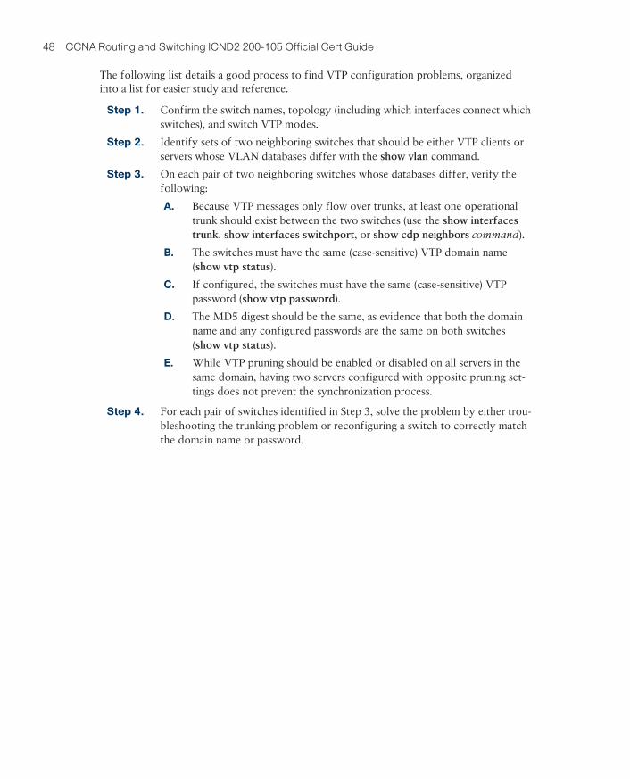
The following list details a good process to find VTP configuration problems, organized into a list for easier study and reference.
Step 1. Confirm the switch names, topology (including which interfaces connect which switches), and switch VTP modes.
Step 2. Identify sets of two neighboring switches that should be either VTP clients or servers whose VLAN databases differ with the show vlan command.
Step 3. On each pair of two neighboring switches whose databases differ, verify the following:
A. Because VTP messages only flow over trunks, at least one operational trunk should exist between the two switches (use the show interfaces
trunk, show interfaces switchport, or show cdp neighbors command).
B. The switches must have the same (case-sensitive) VTP domain name (show vtp status).
C. If configured, the switches must have the same (case-sensitive) VTP password (show vtp password).
D. The MD5 digest should be the same, as evidence that both the domain name and any configured passwords are the same on both switches (show vtp status).
E. While VTP pruning should be enabled or disabled on all servers in the same domain, having two servers configured with opposite pruning set-tings does not prevent the synchronization process.
Step 4. For each pair of switches identified in Step 3, solve the problem by either trou-bleshooting the trunking problem or reconfiguring a switch to correctly match the domain name or password.

Key Topics 49
Besides the suggestion of resetting the VLAN database revision number before installing a new switch, a couple of other good VTP conventions, called best practices, can help avoid some of the pitfalls of VTP:
■ If you do not intend to use VTP, configure each switch to use transparent mode (vtp
mode transparent) or off mode (vtp mode off).
■ If using VTP server or client mode, always use a VTP password. That way a switch that uses default settings (server mode, with no password set) will not accidentally overwrite the production VLAN database if connected to the production network with a trunk.
■ In a lab, if using VTP, always use a different domain name and password than you use in production.
■ Disable trunking with the switchport mode access and switchport nonegotiate com-mands on all interfaces except known trunks, preventing VTP attacks by preventing the dynamic establishment of trunks.

50 CCNA Routing and Switching ICND2 200-105 Official Cert Guide
Chapter 6Figure 6-3 rounds out this topic by showing an example of one key protocol used by 802.1x: Extensible Authentication Protocol (EAP). The switch (the authenticator) uses RADIUS between itself and the AAA server, which itself uses IP and UDP. However, 802.1x, an Ethernet protocol, does not use IP or UDP. But 802.1x wants to exchange some authentication information all the way to the RADIUS AAA server. The solution is to use EAP, as shown in Figure 6-3.
SW1
IP EAPRADIUS
RADIUS with EAP
AuthenticationServerAuthenticatorSupplicant
UDPEth. EAP
EAPoL
Figure 6-3 EAP and Radius Protocol Flows with 802.1x
Key Topics 51
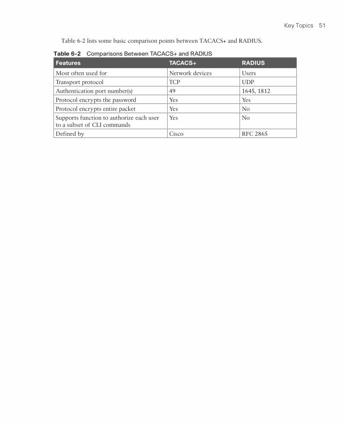
Table 6-2 lists some basic comparison points between TACACS+ and RADIUS.
Table 6-2 Comparisons Between TACACS+ and RADIUS
Features TACACS+ RADIUS
Most often used for Network devices Users
Transport protocol TCP UDP
Authentication port number(s) 49 1645, 1812
Protocol encrypts the password Yes Yes
Protocol encrypts entire packet Yes No
Supports function to authorize each user to a subset of CLI commands
Yes No
Defined by Cisco RFC 2865

52 CCNA Routing and Switching ICND2 200-105 Official Cert Guide
The first big idea with DHCP snooping is the idea of trusted ports and untrusted ports. To understand why, ponder for a moment all the devices that might be connected to one switch. The list includes routers, servers, and even other switches. It includes end-user devic-es, such as PCs. It includes wireless access points, which in turn connect to end-user devices. Figure 6-8 shows a representation.
SW1
DHCPServer
Trusted Untrusted
SW1R1
Figure 6-8 DHCP Snooping Basics: Client Ports Are Untrusted

Key Topics 53
So, the first rule of DHCP snooping is for the switch to trust any ports on which legitimate messages from trusted DHCP servers might arrive. Conversely, by leaving a port untrusted, the switch is choosing to discard any incoming DHCP server-only messages. Figure 6-11 summarizes these points, with the legitimate DHCP server on the left, on a port marked as trusted.
F0/1
DHCP All Messages: Approved! DHCP Server Messages: Rejected!DHCP Client Messages: Check Binding Table
F0/2
SW1DHCP DHCP
Trusted Untrusted
Figure 6-11 Summary of Rules for DHCP Snooping

54 CCNA Routing and Switching ICND2 200-105 Official Cert Guide
DHCP snooping can help reduce risk, particularly because DHCP is such a vital part of most networks. The following list summarizes some of the key points about DHCP snooping for easier exam study:
Trusted ports: Trusted ports allow all incoming DHCP messages.
Untrusted ports, server messages: Untrusted ports discard all incoming messages that are considered server messages.
Untrusted ports, client messages: Untrusted ports apply more complex logic for mes-sages considered client messages. They check whether each incoming DHCP message conflicts with existing DHCP binding table information and, if so, discard the DHCP mes-sage. If the message has no conflicts, the switch allows the message through, which typi-cally results in the addition of new DHCP Binding Table entries.
Rate limiting: Optionally limits the number of received DHCP messages per second, per port.

Key Topics 55
The scenario described so far is literally a stack of switches one above the other. Switch stacking technology allows the network engineer to make that stack of physical switches act like one switch. For instance, if a switch stack was made from the four switches in Figure 6-13, the following would apply:
■ The stack would have a single management IP address.
■ The engineer would connect with Telnet or SSH to one switch (with that one manage-ment IP address), not multiple switches.
■ One configuration file would include all interfaces in all four physical switches.
■ STP, CDP, VTP would run on one switch, not multiple switches.
■ The switch ports would appear as if all are on the same switch.
■ There would be one MAC address table, and it would reference all ports on all physical switches.
56 CCNA Routing and Switching ICND2 200-105 Official Cert Guide
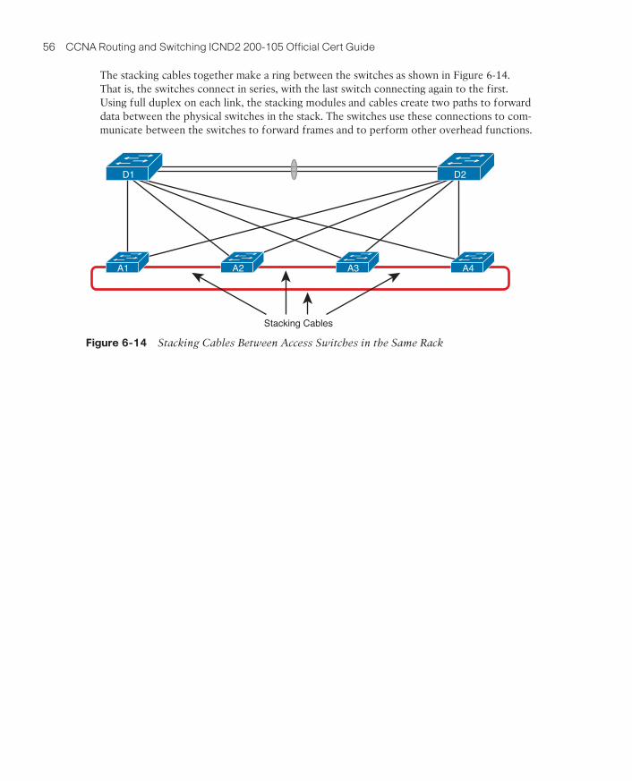
The stacking cables together make a ring between the switches as shown in Figure 6-14. That is, the switches connect in series, with the last switch connecting again to the first. Using full duplex on each link, the stacking modules and cables create two paths to forward data between the physical switches in the stack. The switches use these connections to com-municate between the switches to forward frames and to perform other overhead functions.
Stacking Cables
A1 A2 A3 A4
D1 D2
Figure 6-14 Stacking Cables Between Access Switches in the Same Rack
Key Topics 57
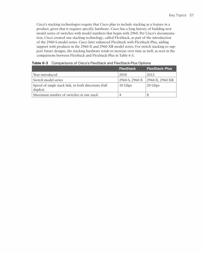
Cisco’s stacking technologies require that Cisco plan to include stacking as a feature in a product, given that it requires specific hardware. Cisco has a long history of building new model series of switches with model numbers that begin with 2960. Per Cisco’s documenta-tion, Cisco created one stacking technology, called FlexStack, as part of the introduction of the 2960-S model series. Cisco later enhanced FlexStack with FlexStack-Plus, adding support with products in the 2960-X and 2960-XR model series. For switch stacking to sup-port future designs, the stacking hardware tends to increase over time as well, as seen in the comparisons between FlexStack and FlexStack-Plus in Table 6-3.
Table 6-3 Comparisons of Cisco’s FlexStack and FlexStack-Plus Options
FlexStack FlexStack-Plus
Year introduced 2010 2013
Switch model series 2960-S, 2960-X 2960-X, 2960-XR
Speed of single stack link, in both directions (full duplex)
10 Gbps 20 Gbps
Maximum number of switches in one stack 4 8

58 CCNA Routing and Switching ICND2 200-105 Official Cert Guide
The following list describes some of the advantages of using switch aggregation. Note that many of the benefits should sound familiar from the switch stacking discussion. The one difference in this list has to do with the active/active data plane.
Multichassis EtherChannel (MEC): Uses the EtherChannel between the two physical switches.
Active/Standby Control Plane: Simpler operation for control plane because the pair acts as one switch for control plane protocols: STP, VTP, EtherChannel, ARP, routing proto-cols.
Active/Active data plane: Takes advantage of forwarding power of supervisors on both switches, with active Layer 2 and Layer 3 forwarding the supervisors of both switches. The switches synchronize their MAC and routing tables to support that process.
Single switch management: Simpler operation of management protocols by running man-agement protocols (Telnet, SSH, SNMP) on the active switch; configuration is synchro-nized automatically with the standby switch.

Key Topics 59
Chapter 7Cisco IOS software supports several IP routing protocols, performing the same general functions:
1. Learn routing information about IP subnets from neighboring routers.
2. Advertise routing information about IP subnets to neighboring routers.
3. If more than one possible route exists to reach one subnet, pick the best route based on a metric.
4. If the network topology changes—for example, a link fails—react by advertising that some routes have failed and pick a new currently best route. (This process is called convergence.)

60 CCNA Routing and Switching ICND2 200-105 Official Cert Guide
IP routing protocols fall into one of two major categories: interior gateway protocols (IGP) or exterior gateway protocols (EGP). The definitions of each are as follows:
■ IGP: A routing protocol that was designed and intended for use inside a single autono-mous system (AS)
■ EGP: A routing protocol that was designed and intended for use between different autonomous systems

Key Topics 61
A routing protocol’s underlying algorithm determines how the routing protocol does its job. The term routing protocol algorithm simply refers to the logic and processes used by different routing protocols to solve the problem of learning all routes, choosing the best route to each subnet, and converging in reaction to changes in the internetwork. Three main branches of routing protocol algorithms exist for IGP routing protocols:
■ Distance vector (sometimes called Bellman-Ford after its creators)
■ Advanced distance vector (sometimes called “balanced hybrid”)
■ Link-state

62 CCNA Routing and Switching ICND2 200-105 Official Cert Guide
Routing protocols choose the best route to reach a subnet by choosing the route with the lowest metric. For example, RIP uses a counter of the number of routers (hops) between a router and the destination subnet. OSPF totals the cost associated with each interface in the end-to-end route, with the cost based on link bandwidth. Table 7-2 lists the most important IP routing protocols for the CCNA exams and some details about the metric in each case.
Table 7-2 IP IGP Metrics
IGP Metric Description
RIP-2 Hop count The number of routers (hops) between a router and the destination subnet
OSPF Cost The sum of all interface cost settings for all links in a route, with the cost defaulting to be based on interface bandwidth
EIGRP Composite of bandwidth and delay
Calculated based on the route’s slowest link and the cumulative delay associated with each interface in the route

Key Topics 63
Routing protocols differ based on whether they are classless routing protocols or classful. Classless routing protocols support variable-length subnet masks (VLSM) as well as manual route summarization. Classless routing protocols support VLSM and manual route summa-rization by sending routing protocol messages that include the subnet masks in the message, whereas the generally older classful routing protocols do not send masks in the routing update messages. Table 7-3 summarizes the key IGP comparison points.
Table 7-3 Interior IP Routing Protocols Compared
Feature RIP-1 RIP-2 EIGRP OSPF IS-IS
Classless/sends mask in updates/supports VLSM
No Yes Yes Yes Yes
Algorithm (DV, advanced DV, LS) DV DV Advanced DV LS LS
Supports manual summarization No Yes Yes Yes Yes
Cisco-proprietary No No Yes1 No No
Routing updates are sent to a multicast IP address
No Yes Yes Yes —
Convergence Slow Slow Fast Fast Fast
1 Although Cisco created EIGRP, and has kept it as a proprietary protocol for many years, Cisco chose to publish EIGRP as an informational RFC in 2013. This allows other vendors to implement EIGRP, while Cisco retains the rights to the protocol.

64 CCNA Routing and Switching ICND2 200-105 Official Cert Guide
The 2-way state is a particularly important OSPF state. At that point, the following major facts are true:
■ The router received a Hello from the neighbor, with that router’s own RID listed as being seen by the neighbor.
■ The router has checked all the parameters in the Hello received from the neighbor, with no problems. The router is willing to become a neighbor.
■ If both routers reach a 2-way state with each other, it means that both routers meet all OSPF configuration requirements to become neighbors. Effectively, at that point, they are neighbors, and ready to exchange their LSDB with each other.

Key Topics 65
This different behavior on OSPF neighbors on a LAN—where some neighbors reach full state and some do not—calls for the use of two more OSPF terms: adjacent and fully adja-cent. Fully adjacent neighbors reach a full state after having exchanged their LSDBs directly. Adjacent neighbors are those DROther routers that (correctly) choose to stay in 2-way state but never reach a full state. Table 7-5 summarizes these key concepts and terms related to OSPF states.
Table 7-5 Stable OSPF Neighbor States and Their Meanings
Neighbor State
Adjacency Lingo
Meaning
2-way Adjacent The neighbor has sent a Hello that lists the local router’s RID in the list of seen routers, also implying that neighbor verification checks all passed. If both neighbors are DROther routers, the neighbors should remain in this state.
Full Fully adjacent
Both routers know the exact same LSDB details and are fully adjacent, meaning they have completed the exchange of LSDB contents.

66 CCNA Routing and Switching ICND2 200-105 Official Cert Guide
Once SPF has identified a route, OSPF calculates the metric for a route as follows:
The sum of the OSPF interface costs for all outgoing interfaces in the route

Key Topics 67
Figure 7-11 shows an example with three possible routes from R1 to Subnet X (172.16.3.0/24) at the bottom of the figure.
Cost 20
Cost 30
Cost 30Cost 10
Cost 60
Cost 20Cost 180
Cost 5
Cost 10
Subnet X(172.16.3.0/24)
Cost 40
Possible Route
R1
R2
R3R7
R4
R5
R6
R8Legend:
Figure 7-11 SPF Tree to Find R1’s Route to 172.16.3.0/24

68 CCNA Routing and Switching ICND2 200-105 Official Cert Guide
OSPF area design follows a couple of basic rules. To apply the rules, start with a clean draw-ing of the internetwork, with routers, and all interfaces. Then, choose the area for each router interface, as follows:
■ Put all interfaces connected to the same subnet inside the same area.
■ An area should be contiguous.
■ Some routers may be internal to an area, with all interfaces assigned to that single area.
■ Some routers may be Area Border Routers (ABR), because some interfaces connect to the backbone area, and some connect to nonbackbone areas.
■ All nonbackbone areas must connect to the backbone area (area 0) by having at least one ABR connected to both the backbone area and the nonbackbone area.
Key Topics 69
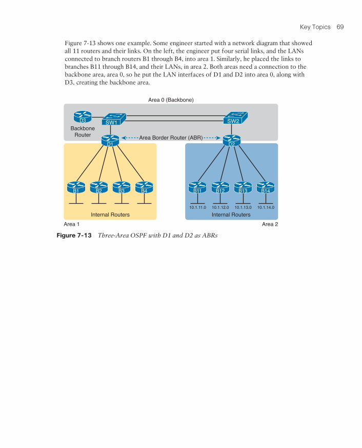
Figure 7-13 shows one example. Some engineer started with a network diagram that showed all 11 routers and their links. On the left, the engineer put four serial links, and the LANs connected to branch routers B1 through B4, into area 1. Similarly, he placed the links to branches B11 through B14, and their LANs, in area 2. Both areas need a connection to the backbone area, area 0, so he put the LAN interfaces of D1 and D2 into area 0, along with D3, creating the backbone area.
B1 B2
D1
B3 B4 B11 B12
D2
B13 B14
D3
Internal Routers
BackboneRouter Area Border Router (ABR)
Area 0 (Backbone)
Area 1 Area 2
Internal Routers10.1.11.0 10.1.12.0 10.1.13.0 10.1.14.0
SW1 SW2
Figure 7-13 Three-Area OSPF with D1 and D2 as ABRs

70 CCNA Routing and Switching ICND2 200-105 Official Cert Guide
The figure also shows a few important OSPF area design terms. Table 7-7 summarizes the meaning of these terms, plus some other related terms, but pay closest attention to the terms from the figure.
Table 7-7 OSPF Design Terminology
Term Description
Area Border Router (ABR)
An OSPF router with interfaces connected to the backbone area and to at least one other area
Backbone router A router connected to the backbone area (includes ABRs)
Internal router A router in one area (not the backbone area)
Area A set of routers and links that shares the same detailed LSDB information, but not with routers in other areas, for better efficiency
Backbone area A special OSPF area to which all other areas must connect—area 0
Intra-area route A route to a subnet inside the same area as the router
Interarea route A route to a subnet in an area of which the router is not a part

Key Topics 71
Chapter 8The key to understanding the traditional OSPFv2 configuration shown in this first example is to understand the OSPF network command. The OSPF network command compares the first parameter in the command to each interface IP address on the local router, trying to find a match. However, rather than comparing the entire number in the network command to the entire IPv4 address on the interface, the router can compare a subset of the octets, based on the wildcard mask, as follows:
Wildcard 0.0.0.0: Compare all 4 octets. In other words, the numbers must exactly match.
Wildcard 0.0.0.255: Compare the first 3 octets only. Ignore the last octet when compar-ing the numbers.
Wildcard 0.0.255.255: Compare the first 2 octets only. Ignore the last 2 octets when comparing the numbers.
Wildcard 0.255.255.255: Compare the first octet only. Ignore the last 3 octets when comparing the numbers.
Wildcard 255.255.255.255: Compare nothing—this wildcard mask means that all addresses will match the network command.

72 CCNA Routing and Switching ICND2 200-105 Official Cert Guide
For example, first, examine the list of neighbors known on Router R3 from the configura-tion in Examples 8-1, 8-2, and 8-3. R3 should have one neighbor relationship with R1, over the serial link. It also has two neighbor relationships with R4, over the two different VLANs to which both routers connect. Example 8-4 shows all three.
Example 8-4 OSPF Neighbors on Router R3 from Figure 8-2
R3# show ip ospf neighbor
Neighbor ID Pri State Dead Time Address Interface
1.1.1.1 0 FULL/ - 00:00:33 10.1.13.1 Serial0/0/0
10.1.24.4 1 FULL/DR 00:00:35 10.1.3.130 GigabitEthernet0/0.342
10.1.24.4 1 FULL/DR 00:00:36 10.1.3.4 GigabitEthernet0/0.341

Key Topics 73
To choose its RID, a Cisco router uses the following process when the router reloads and brings up the OSPF process. Note that when one of these steps identifies the RID, the pro-cess stops.
1. If the router-id rid OSPF subcommand is configured, this value is used as the RID.
2. If any loopback interfaces have an IP address configured, and the interface has an interface status of up, the router picks the highest numeric IP address among these loopback interfaces.
3. The router picks the highest numeric IP address from all other interfaces whose inter-face status code (first status code) is up. (In other words, an interface in up/down state will be included by OSPF when choosing its router ID.)
74 CCNA Routing and Switching ICND2 200-105 Official Cert Guide
When a router does not need to discover neighbors off some interface, the engineer has a couple of configuration options. First, by doing nothing, the router keeps sending the mes-sages, wasting some small bit of CPU cycles and effort. Alternately, the engineer can config-ure the interface as an OSPF passive interface, telling the router to do the following:
■ Quit sending OSPF Hellos on the interface.
■ Ignore received Hellos on the interface.
■ Do not form neighbor relationships over the interface.

Key Topics 75
The only router that has a multiarea config is an ABR, by virtue of the configuration refer-ring to more than one area. In this design (as shown in Figure 8-4), only Router R1 acts as an ABR, with interfaces in three different areas. Example 8-14 shows R1’s OSPF configuration. Note that the configuration does not state anything about R1 being an ABR; instead, it uses multiple network commands, some placing interfaces into area 0, some into area 23, and some into area 4.
Example 8-14 OSPF Multiarea Configuration on Router R1
interface GigabitEthernet0/0.11
encapsulation dot1q 11
ip address 10.1.1.1 255.255.255.0
!
interface GigabitEthernet0/0.12
encapsulation dot1q 12
ip address 10.1.2.1 255.255.255.0
!
interface GigabitEthernet0/1
ip address 10.1.14.1 255.255.255.0
!
interface serial 0/0/0
ip address 10.1.12.1 255.255.255.0
!
interface serial 0/0/1
ip address 10.1.13.1 255.255.255.0
!
router ospf 1
network 10.1.1.1 0.0.0.0 area 0
network 10.1.2.1 0.0.0.0 area 0
network 10.1.12.1 0.0.0.0 area 23
network 10.1.13.1 0.0.0.0 area 23
network 10.1.14.1 0.0.0.0 area 4
router-id 1.1.1.1
passive-interface GigabitEthernet0/0.11
passive-interface GigabitEthernet0/0.12
76 CCNA Routing and Switching ICND2 200-105 Official Cert Guide
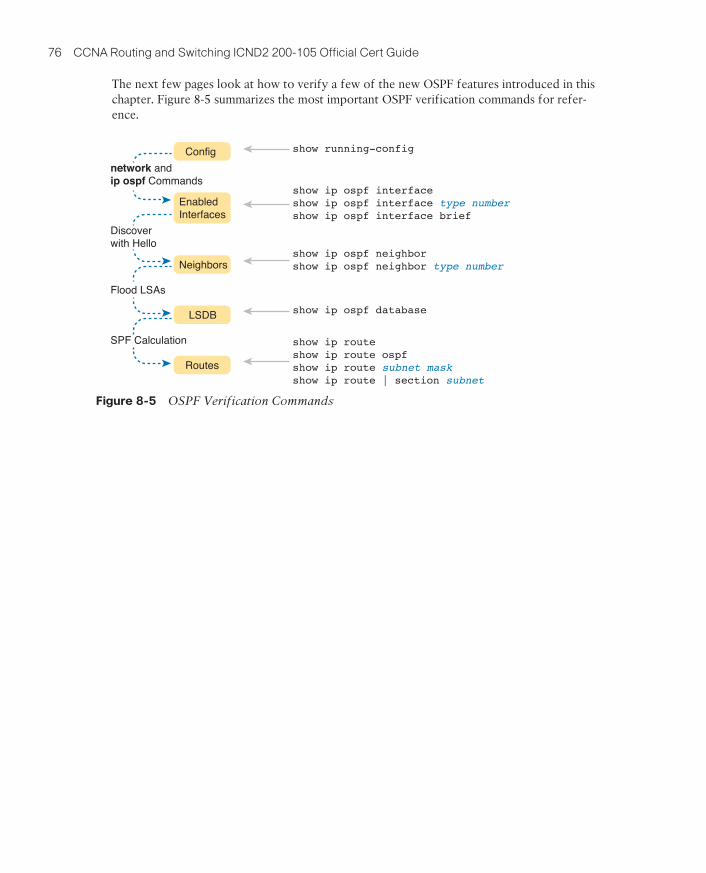
The next few pages look at how to verify a few of the new OSPF features introduced in this chapter. Figure 8-5 summarizes the most important OSPF verification commands for refer-ence.
network andip ospf Commands
Discover with Hello
Flood LSAs
SPF Calculation
Config
EnabledInterfaces
Routes
LSDB
Neighbors
show running-config
show ip ospf interfaceshow ip ospf interface type numbershow ip ospf interface brief
show ip ospf neighborshow ip ospf neighbor type number
show ip ospf database
show ip routeshow ip route ospfshow ip route subnet maskshow ip route | section subnet
Figure 8-5 OSPF Verification Commands

Key Topics 77
The easiest place to make a configuration oversight with a multiarea configuration is to place an interface into the wrong OSPF area. Several commands mention the OSPF area. The show ip protocols command basically relists the OSPF network configuration com-mands, which indirectly identify the interfaces and areas. Also, the show ip ospf interface and show ip ospf interface brief commands directly show the area configured for an inter-face; Example 8-15 shows an example of the briefer version of these commands.
Example 8-15 Listing the OSPF-Enabled Interfaces and the Matching OSPF Areas
R1# show ip ospf interface brief
Interface PID Area IP Address/Mask Cost State Nbrs F/C
Gi0/0.12 1 0 10.1.2.1/24 1 DR 0/0
Gi0/0.11 1 0 10.1.1.1/24 1 DR 0/0
Gi0/1 1 4 10.1.14.1/24 1 BDR 1/1
Se0/0/1 1 23 10.1.13.1/24 64 P2P 1/1
Se0/0/0 1 23 10.1.12.1/24 64 P2P 1/1

78 CCNA Routing and Switching ICND2 200-105 Official Cert Guide
Figure 8-6 shows the idea of how OSPF advertises the default route, with the specific OSPF configuration. In this case, a company connects to an ISP with its Router R1. That router has a static default route (destination 0.0.0.0, mask 0.0.0.0) with a next-hop address of the ISP router. Then, the use of the OSPF default-information originate command (Step 2) makes the router advertise a default route using OSPF to the remote routers (B1 and B2).
1
2
2
Internet
OSPFv2 Advertises Default
OSPFv2 Advertises Default
192.0.2.1
G0/3
G0/2
G0/1
G0/1
G0/1 ip route 0.0.0.0 0.0.0.0 192.0.2.1
ISP1
B02
B01
R1
default-information originate
default-information originate
Figure 8-6 Using OSPF to Create and Flood a Default Route

Key Topics 79
For convenient study, the following list summarizes the rules for how a router sets its OSPF interface costs:
1. Set the cost explicitly, using the ip ospf cost x interface subcommand, to a value between 1 and 65,535, inclusive.
2. Change the interface bandwidth with the bandwidth speed command, with speed being a number in kilobits per second (Kbps).
3. Change the reference bandwidth, using router OSPF subcommand auto-cost
reference-bandwidth ref-bw, with a unit of megabits per second (Mbps).

80 CCNA Routing and Switching ICND2 200-105 Official Cert Guide
Basically, the show ip protocols command output differs depending on the style of con-figuration, either relisting the interfaces when using interface configuration or relisting the network commands if using network commands.
Next, the show ip ospf interface [interface] command lists details about OSPF settings for the interface(s) on which OSPF is enabled. The output also makes a subtle reference to whether that interface was enabled for OSPF with the old or new configuration style. As seen in Example 8-22, R2’s new-style interface configuration results in the highlighted text, “Attached via Interface Enable,” whereas R3’s old-style configuration lists “Attached via Network Statement.”
Example 8-22 Differences in show ip ospf interface Output with OSPFv2 Interface Configuration
R2# show ip ospf interface g0/0
GigabitEthernet0/0 is up, line protocol is up
Internet Address 10.1.23.2/24, Area 23, Attached via Interface Enable
Process ID 1, Router ID 22.2.2.2, Network Type BROADCAST, Cost: 1
Topology-MTID Cost Disabled Shutdown Topology Name
0 1 no no Base
Enabled by interface config, including secondary ip addresses
Transmit Delay is 1 sec, State DR, Priority 1
Designated Router (ID) 2.2.2.2, Interface address 10.1.23.2
Backup Designated router (ID) 3.3.3.3, Interface address 10.1.23.3
! Showing only the part that differs on R3:
R3# show ip ospf interface g0/0GigabitEthernet0/0 is up, line protocol is up
Internet Address 10.1.23.3/24, Area 23, Attached via Network Statement
! … ending line omitted for brevity

Key Topics 81
Chapter 9So, with so many IPv4 routing protocols, how does a network engineer choose which routing protocol to use? Well, consider two key points about EIGRP that drive engineers toward wanting to use it:
■ EIGRP uses a robust metric based on both link bandwidth and link delay, so routers make good choices about the best route to use (see Figure 9-2).
■ EIGRP converges quickly, meaning that when something changes in the internetwork, EIGRP quickly finds the currently best loop-free routes to use.

82 CCNA Routing and Switching ICND2 200-105 Official Cert Guide
While Figure 9-3 shows how R1 learns the routes with RIP updates, Figure 9-4 gives a better view into R1’s distance vector logic. R1 knows three routes, each with
Distance: The metric for a possible route
Vector: The direction, based on the next-hop router for a possible route
To R2, 4 Hops
To R5, 3 Hops
I See 3 Routes to X:- 4 Hops to R2- 3 Hops to R5 - 2 Hops to R7
Subnet X
To R7, 2 Hops
R1
R2
R5
R7
Figure 9-4 Graphical Representation of the DV Concept
Note that R1 knows no other topology information about the internetwork. Unlike LS pro-tocols, RIP’s DV logic has no idea about the overall topology, instead just knowing about next-hop routers and metrics.

Key Topics 83
Split horizon is difficult to learn by reading words, and much easier to learn by seeing an example. Figure 9-6 continues the same example as 9-5, but focusing on R1’s RIP update sent out R1’s S0/0 interface to R2. This figure shows R1’s routing table with three light-colored routes, all of which list S0/0 as the outgoing interface. When building the RIP update to send out S0/0, split-horizon rules tell R1 to ignore those light-colored routes, because all three routes list S0/0 as the outgoing interface. Only the bold route, which does not list S0/0 as an outgoing interface, can be included in the RIP update sent out S0/0.
G0/0 - 172.30.21.0 /24
S0/1/0S0/0
G0/1 - 172.30.22.0 /24
R1 IP Routing TableSourceRIPRIPConn.Conn.
Subnet172.30.21.0/24172.30.22.0/24172.30.1.0/24172.30.11.0/24
Out Int.S0/0S0/0S0/0G0/0
Next-Hop172.30.1.2172.30.1.2N/AN/A
Metric1100
RIP Update
Only Bold Route Has InterfaceOther Than S0/0
172.30.11.0, metric 1
R1 R2
G0/0 - 172.30.11.0 /24 172.30.1.0 /24
172.30.1.2
Figure 9-6 R1 Does Not Advertise Three Routes Due to Split Horizon

84 CCNA Routing and Switching ICND2 200-105 Official Cert Guide
Table 9-2 summarizes the features discussed in this chapter, for RIPv2, EIGRP, and OSPFv2. Following the table, the second major section of this chapter begins, which moves into depth about the specifics of how EIGRP works.
Table 9-2 Interior IP Routing Protocols Compared
Feature RIPv2 EIGRP OSPFv2
Metric is based on Hop count Bandwidth and delay
Cost
Sends periodic full updates Yes No No
Sends periodic Hello messages No Yes Yes
Uses route poisoning for failed routes Yes Yes Yes
Uses split horizon to limit updates about working routes
Yes Yes No
Address to which messages are sent 224.0.0.9 224.0.0.10 224.0.0.5, 224.0.0.6
Metric considered to be infinite 16 232 – 1 224 – 1

Key Topics 85
Once another EIGRP router is discovered using Hello messages, routers must perform some basic checking of each potential neighbor before that router becomes an EIGRP neighbor. (A potential neighbor is a router from which an EIGRP Hello has been received.) Then the router checks the following settings to determine whether the router should be allowed to be a neighbor:
■ It must pass the authentication process if used.
■ It must use the same configured autonomous system number (which is a configuration setting).
■ The source IP address used by the neighbor’s Hello must be in the same subnet as the local router’s interface IP address/mask.
■ The routers’ EIGRP K-values must match. (However, Cisco recommends to not change these values.)

86 CCNA Routing and Switching ICND2 200-105 Official Cert Guide
Figure 9-9 summarizes many of the details discussed so far in this section, from top to bot-tom. It first shows neighbor discovery with Hellos, the sending of full updates, the mainte-nance of the neighbor relationship with ongoing Hellos, and partial updates.
B A
Neighbor Discovery (Hello)
Full Routing Update
Continuous Hellos
Partial Updates (Status Changesand New Subnet Info)
Neighbor Discovery (Hello)
Full Routing Update
Continuous Hellos
Partial Updates (Status Changesand New Subnet Info)
ReliableUpdate
Figure 9-9 Full and Partial EIGRP Updates

Key Topics 87
First, before getting into how EIGRP converges, you need to know a few additional EIGRP terms. With EIGRP, a local router needs to consider its own calculated metric for each route, but at the same time, the local router considers the next-hop router’s calculated met-ric for that same destination subnet. And EIGRP has special terms for those metrics, as fol-lows:
■ Feasible distance (FD): The local router’s composite metric of the best route to reach a subnet, as calculated on the local router
■ Reported distance (RD): The next-hop router’s best composite metric for that same subnet

88 CCNA Routing and Switching ICND2 200-105 Official Cert Guide
A router determines whether a route is a feasible successor based on the feasibility condi-tion:
If a nonsuccessor route’s RD is less than the FD, the route is a feasible successor route.
Although it is technically correct, this definition is much more understandable with an example. Figure 9-13 begins an example in which router E chooses its best route to subnet 1. Router E learns three routes to subnet 1, with next-hop routers B, C, and D. The figure shows the metrics as calculated on router E, as listed in router E’s EIGRP topology table. Router E finds that the route through router D has the lowest metric, making that router E’s successor route for subnet 1. Router E adds that route to its routing table, as shown. The FD is the metric calculated for this route, a value of 14,000 in this case.

Key Topics 89
Figure 9-14 demonstrates that one of the two other routes meets the feasibility condition and is therefore a feasible successor route. The figure shows an updated version of Figure 9-13. Router E uses the following logic to determine that the route through router B is not a feasible successor route, but the route through router C is, as follows:
■ Router E compares the FD of 14,000 to the RD of the route through router B (15,000). Router B’s RD is worse than router E’s FD, so this route is not a feasible successor.
■ Router E compares the FD of 14,000 to the RD of the route through router C (13,000). Router C’s RD is better than router E’s FD, making this route a feasible successor.
Subnet 1
Router E Routing Table
Subnet 1 Metric 14,000, Through D
Feas. Successor
B
CE A
D
Metric RDRouter B — 19,000 15,000Router C —17,500 13,000Router D — 14,000 10,000
Router E Topology Tablefor Subnet 1:
RD < 14,000
Figure 9-14 Route Through Router C Is a Feasible Successor
If the route to subnet 1 through router D fails, router E can immediately put the route through router C into the routing table without fear of creating a loop. Convergence occurs almost instantly in this case.

90 CCNA Routing and Switching ICND2 200-105 Official Cert Guide
Chapter 10The next several pages walk through the verification steps to confirm a working internet-work that uses EIGRP. Figure 10-2 shows the progression of concepts from top to bottom on the left, with a reference for the various show commands on the right. The topics to fol-low use that same sequence.
show running-config
show ip eigrp interfacesshow ip eigrp interfaces detailshow ip eigrp interfaces type numbershow ip protocols
show ip eigrp neighborsshow ip eigrp neighbors type numbershow ip protocols
show ip eigrp topologyshow ip eigrp topology subnet/prefixshow ip eigrp topology | section subnet
show ip routeshow ip route eigrpshow ip route subnet maskshow ip route | section subnet
network Commands
Discover with Hello
Update
Calculate
Config
EnabledInterfaces
Routes
Topology
Neighbors
Figure 10-2 Roadmap of Topics (Left) and Verification Commands (Right)

Key Topics 91
For configurations that use the wildcard mask option, the format of the show ip protocols command differs a little. Example 10-5 shows an excerpt of the show ip protocols com-mand from R3. R3 uses the three network commands shown earlier in Example 10-2.
Example 10-5 EIGRP Wildcard Masks Listed with show ip protocols on R3
R3# show ip protocols
! Lines omitted for brevity
Automatic Summarization: disabled
Maximum path: 4
Routing for Networks:
10.1.3.0/24
10.1.4.0/24
10.1.6.0/24
! Lines omitted for brevity
To interpret the meaning of the highlighted portions of this show ip protocols command, you have to do a little math. The output lists a number in the format of /x (in this case, /24). It represents a wildcard mask with x binary 0s, or in this case, 0.0.0.255.

92 CCNA Routing and Switching ICND2 200-105 Official Cert Guide
Before moving on from the show ip protocols command, take a moment to read some of the other details of this command’s output from Example 10-4. For instance, it lists the EIGRP router ID (RID), which for R1 is 10.1.5.1. EIGRP allocates its RID just like OSPF, based on the following:
1. The value configured with the eigrp router-id number EIGRP subcommand
2. The numerically highest IP address of an up/up loopback interface at the time the EIGRP process comes up
3. The numerically highest IP address of a nonloopback interface at the time the EIGRP process comes up
The only difference compared to OSPF is that the EIGRP RID is configured with the eigrp
router-id value router subcommand, whereas OSPF uses the router-id value subcommand.

Key Topics 93
To help make sure the items are clear, Figure 10-4 breaks down these items, using these same details about subnet 10.1.3.0/24 from R1’s EIGRP topology table.
Number of Successors
Feasible Distance (FD)
Outgoing InterfaceMetric
Reported Distance (RD)Next-Hop Router
Subnet/Mask
P 10.1.3.0/24, 1 successors, FD is 2172416
via 10.1.4.3 (2172416/28160), Serial0/0/1
Figure 10-4 Reference to Fields in the Output from show ip eigrp topology

94 CCNA Routing and Switching ICND2 200-105 Official Cert Guide
To see the feasible successor route, and why it is an FS, work through the various numbers in the output in Example 10-11. Or, work through that same output, repeated in Figure 10-7, with notes. In either case, the logic works like the notes in this list:
■ Per the first line, one successor route exists.
■ The FD is 2,684,416.
■ Of the two lines that begin with via—the two possible routes listed—the first route’s metric of 2,684,416 equals the FD. As a result, this first line lists the details of the one successor route.
■ The other line that begins with via has a metric (first number in parentheses) of 2,854,912, which differs from the FD value of 2,684,416. As a result, this route is not a successor route.
■ The second line that begins with via has a reported distance (RD, the second number) of 2,342,912, which is less than the FD of 2,684,416. This second route meets the feasibil-ity condition, making it a feasible successor route.
P 10.1.33.0/24, 1 successors, FD is 2684416
Number of Successors
Feasible Distance (FD)
RD of Feasible Successor
RD < FD: Meets Feasibility Condition!
Successor
Feasible Successor via 10.1.5.2 (2854912/2342912), Serial0/0/0via 10.1.4.3 (2684416/2172416), Serial0/0/1
Figure 10-7 Identifying the Feasible Successor Route

Key Topics 95
The following list summarizes the key points about variance:
■ The variance is multiplied by the current FD (the metric of the best route to reach the subnet).
■ Any FS routes whose calculated metric is less than or equal to the product of variance times the FD are added to the IP routing table, assuming that the maximum-paths setting allows more routes.
■ Routes that are neither successor nor FS can never be added to the IP routing table, regardless of the variance setting, because doing so may cause packets to loop.

96 CCNA Routing and Switching ICND2 200-105 Official Cert Guide
A routing protocol that uses autosummary automatically creates a summary route under certain conditions. In particular, when a router sits at the boundary between classful net-works—that is, with some interfaces in one Class A, B, or C network and other interfaces in another Class A, B, or C network—the router summarizes routes. Routes from one classful network are summarized as one route to the entire Class A, B, or C network. More formally:
Routes related to subnets in network X, when advertised out an interface whose IP address is not in network X, are summarized and advertised as one route. That route is for the entire Class A, B, or C network X.

Key Topics 97
To better understand what the terms contiguous and discontiguous mean in networking, refer to the following two formal definitions when reviewing the example of a discontigu-ous classful network that follows:
■ Contiguous network: A classful network in which packets sent between every pair of subnets can pass only through subnets of that same classful network, without having to pass through subnets of any other classful network
■ Discontiguous network: A classful network in which packets sent between at least one pair of subnets must pass through subnets of a different classful network

98 CCNA Routing and Switching ICND2 200-105 Official Cert Guide
Figure 10-10 creates an expanded version of the internetwork shown in Figure 10-9 to cre-ate an example of a discontiguous network 10.0.0.0. In this design, some subnets of net-work 10.0.0.0 sit off R1 on the left, whereas others still connect to R3 on the right. Packets passing between subnets on the left to subnets on the right must pass through subnets of Class B network 172.16.0.0.
172.16.3.0/24
R1 R3R2
10.3.4.0
10.3.5.0
10.3.6.0
10.3.7.0
10.2.1.0
10.2.2.0
10.2.3.0
10.2.4.0
S0/0/0S0/0/1
Which Route toNetwork 10.0.0.0
Do I Believe?I Have a Routeto 10.0.0.0/8
I Have a Routeto 10.0.0.0/8
172.16.2.0/242.1 3.3
Figure 10-10 Discontiguous Network 10.0.0.0

Key Topics 99
Chapter 11This section examines the second major troubleshooting step outlined in the previous sec-tion of the chapter: how to verify the interfaces on which the routing protocol has been enabled. Both EIGRP and OSPF configuration enable the routing protocol on an interface by using the network router subcommand. For any interfaces matched by the network commands, the routing protocol tries the following two actions:
■ Attempt to find potential neighbors on the subnet connected to the interface
■ Advertise the subnet connected to that interface

100 CCNA Routing and Switching ICND2 200-105 Official Cert Guide
Table 11-1 summarizes the commands that identify the interfaces on which OSPFv2 and EIGRP are enabled for easier reference.
Table 11-1 Key Commands to Find Routing Protocol-Enabled Interfaces
Command Key Information Lists Passive Interfaces?
show ip eigrp interfaces
Lists the interfaces on which EIGRP is enabled (based on the network commands), excluding passive interfaces.
No
show ip ospf interface brief
Lists the interfaces on which the OSPFv2 is enabled (based on the network router subcommands or ip ospf interface subcommands), including passive interfaces.
Yes
show ip protocols Lists the contents of the network configuration commands for each routing process, and lists enabled but passive interfaces.
Yes
NOTE All the commands in Table 11-1 list the interfaces regardless of interface status, in effect telling you the results of the network and passive-interface configuration commands.

Key Topics 101
Table 11-2 lists the neighbor requirements for both EIGRP and OSPF. Following the table, the next few pages examine some of these settings for both EIGRP and OSPF, again using examples based on Figure 11-3.
NOTE Even though it is important to study and remember the items in this table, when reading this chapter the first time, just keep reading. When later reviewing the chapter or part, make sure you remember the details in the table.
Table 11-2 Neighbor Requirements for EIGRP and OSPF
Requirement EIGRP OSPF
Interfaces must be in an up/up state. Yes Yes
Interfaces must be in the same subnet. Yes Yes
Access control lists (ACL) must not filter routing protocol messages. Yes Yes
Must pass routing protocol neighbor authentication (if configured). Yes Yes
Must use the same ASN/PID on the router configuration command. Yes No
Hello and hold/dead timers must match. No Yes
Router IDs (RID) must be unique. No1 Yes
K-values must match. Yes N/A
Must be in the same area. N/A Yes
1 Having duplicate EIGRP RIDs does not prevent routers from becoming neighbors, but it can cause problems when external EIGRP routes are added to the routing table.
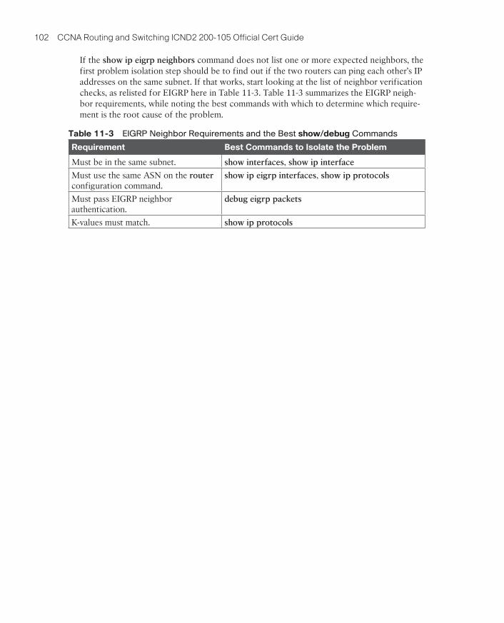
102 CCNA Routing and Switching ICND2 200-105 Official Cert Guide
If the show ip eigrp neighbors command does not list one or more expected neighbors, the first problem isolation step should be to find out if the two routers can ping each other’s IP addresses on the same subnet. If that works, start looking at the list of neighbor verification checks, as relisted for EIGRP here in Table 11-3. Table 11-3 summarizes the EIGRP neigh-bor requirements, while noting the best commands with which to determine which require-ment is the root cause of the problem.
Table 11-3 EIGRP Neighbor Requirements and the Best show/debug Commands
Requirement Best Commands to Isolate the Problem
Must be in the same subnet. show interfaces, show ip interface
Must use the same ASN on the router configuration command.
show ip eigrp interfaces, show ip protocols
Must pass EIGRP neighbor authentication.
debug eigrp packets
K-values must match. show ip protocols

Key Topics 103
If the show ip ospf neighbor command does not list one or more expected neighbors, you should confirm, even before moving on to look at OSPF neighbor requirements, that the two routers can ping each other on the local subnet. But if the two neighboring routers can ping each other, and the two routers still do not become OSPF neighbors, the next step is to examine each of the OSPF neighbor requirements. Table 11-4 summarizes the require-ments, listing the most useful commands with which to find the answers.
Table 11-4 OSPF Neighbor Requirements and the Best show/debug Commands
Requirement Best show Command Best debug Command
Must be in the same subnet. show interfaces debug ip ospf hello
Hello and dead timers must match. show ip ospf interface debug ip ospf hello
Must be in the same area. show ip ospf interface brief debug ip ospf adj
RIDs must be unique. show ip ospf (N/A; log messages identify this problem)
Must pass any neighbor authentication.
show ip ospf interface debug ip ospf adj

104 CCNA Routing and Switching ICND2 200-105 Official Cert Guide
Chapter 12Figure 12-3 shows an example with two competing routes to reach prefix 192.0.2.0/24, one with a shorter AS_Path length. The enterprise advertises its public prefix 192.0.2.0/24 to ISP1, which then advertises it to other ISPs. ISP3 eventually learns two possible routes to that prefix, one that lists an AS_Path with three ASNs, and the shorter one with two ASNs (the best path, as noted with the >).
Enterprise
192.0.2.0/24
ASN 1001
ISP1
ASN 1
ISP2
ASN 2
ISP3
Prefix 192.0.2.0/24> 192.0.2.0/24
eBGP
eBGP eBGP
eBGP
AS_Path2-1-10011-1001
ASN 3
Figure 12-3 ASNs and Shortest AS_Path as Chosen at ISP3 for Prefix 192.0.2.0/24

Key Topics 105
The term single homed (used in the one BGP exam topic) refers to a particular Internet edge design with a single link to one ISP, as shown in Figure 12-4. A single-homed design has a single link between the enterprise and an ISP. You would typically find a single-homed Internet edge design used when connecting an enterprise branch office to the Internet, or for a simple connection from a core site at the enterprise.
Enterprise ISPSingle Homed
Figure 12-4 Single-Homed Design: Single Link, One Home (ISP)

106 CCNA Routing and Switching ICND2 200-105 Official Cert Guide
Next, consider what routes should be advertised between two eBGP peers at the Internet edge. Begin with routes advertised by the enterprise to the ISP, as with a typical enterprise site on the left side of Figure 12-7. In that particular design, the enterprise uses
Private 10.0.0.0/8: Like many companies, this enterprise uses private IP network 10.0.0.0 for most hosts in the enterprise.
Public 192.0.2.0/24: The public IPv4 network assigned to the company. As shown, it has been subnetted, one subnet for use with NAT, the other used for a DMZ with public-facing web servers.
eBGP
192.0.2.0/24R1 ISP1
10.0.0.0/8
FW1DMZ
192.0.2.128/26
192.0.2.0/29
Loopback1
NAT
Figure 12-7 Public and Private IPv4 Address Prefixes Advertised to an ISP

Key Topics 107
Figure 12-9 shows the basic concept. At Step 1, the ISP advertises a default route with eBGP. At Step 2, router R1 takes the steps necessary with its IGP so that the IGP then reacts to the eBGP-learned default route, advertising a default route into the enterprise with the IGP.
Enterprise
IGP –Default
0.0.0.0/0
ISP1
R1 ISP1
eBGP
1
2
Figure 12-9 ISP Advertises a Default Route; IGP Propagates
108 CCNA Routing and Switching ICND2 200-105 Official Cert Guide
BGP configuration, in contrast, does none of the actions in the preceding list. (BGP does use a network command, but for a different purpose.) BGP does form neighbor relationships, but BGP has no concept of being enabled on an interface, or of dynamically discovering neighbors. Instead, with BGP:
■ Predefine neighbors with the neighbor ip-address remote-as asn BGP subcommand
■ Advertise about prefixes that have been added to the BGP table using
■ The BGP network command
■ Route redistribution
■ By learning prefi xes from a neighbor

Key Topics 109
Of these, only the bgp peer-ip-address remote-as command is required. The router bgp asn global command defines the local router’s ASN, and each bgp peer-ip-address remote-as asn command defines a neighbor’s IP address and ASN, as shown in Figure 12-12.
ASN 1
G0/2G0/2198.51.100.1
G0/1 198.51.100.2R1 ISP1
ASN 1001
router bgp 1001
router bgp 1
neighbor 198.51.100.2 remote-as 1
neighbor 198.51.100.1 remote-as 1001
Figure 12-12 Design for Sample eBGP Neighbor Configurations

110 CCNA Routing and Switching ICND2 200-105 Official Cert Guide
The previous configuration gets BGP started, and causes an eBGP neighbor relationship to form, but it does not complete the initial configuration. Remember, from earlier Figure 12-10, that BGP must also add entries to its BGP table before it can then advertise that entry (NLRI and associated PAs). With the configuration so far, Routers R1 and ISP1 should be eBGP peers, but not yet have any BGP table entries to send to each other. Example 12-2 shows some sample output to confirm the neighbor relationship, and to confirm that BGP has an empty BGP table. The explanation follows the example.
Example 12-2 eBGP Neighbor States and TCP Connection
R1# show tcp brief
TCB Local Address Foreign Address (state)
0D0D3F00 198.51.100.1.63680 198.51.100.2.179 ESTAB
R1# show ip bgp summaryBGP router identifier 192.0.2.1, local AS number 1001
BGP table version is 1, main routing table version 1
Neighbor V AS MsgRcvd MsgSent TblVer InQ OutQ Up/Down State/PfxRcd
198.51.100.2 4 1 2 2 1 0 0 00:00:49 0
R1#
R1# show ip bgpR1#

Key Topics 111
Figure 12-14 details the logic of the BGP network prefix mask DDN-mask command. The network command lists a prefix and DDN-style mask (Step 1 in the figure). IOS then compares that prefix and mask to the prefix/mask for the routes in the IPv4 routing table. BGP looks for an exact match (Step 2), meaning that the BGP network command’s prefix and mask both exactly match a prefix and mask in a route in the routing table. If a match is found (Step 3), BGP on that router creates a matching BGP table entry. BGP advertises the best valid routes from its BGP table to its BGP peers (Step 4).
Router Internals
network 192.0.2.0 mask 255.255.255.0
Update1
2
34
IP Routing Table10.1.1.0/2410.1.2.0/24192.0.2.0/24
BGP Table
NLRI192.0.2.0/24
Figure 12-14 Configuration Concept: the BGP network Command

112 CCNA Routing and Switching ICND2 200-105 Official Cert Guide
Chapter 13Now back to the idea of the speed of a leased line. What can you actually buy? Basically, at slower speeds, you get any multiple of 64 Kbps, up to T1 speed. At faster speeds, you can get multiples of T1 speed, up to T3 speed. Table 13-3 summarizes the speeds typically seen in the United States, with a few from Europe.
Table 13-3 WAN Speed Summary
Names of Line Bit Rate
DS0 64 Kbps
Fractional T1 Multiples of 64 Kbps, up to 24X
DS1 (T1) 1.544 Mbps (24 DS0s, for 1.536 Mbps, plus 8 Kbps overhead)
E1 (Europe) 2.048 Mbps (32 DS0s)
Fractional T3 Multiples of 1.536 Mbps, up to 28X
DS3 (T3) 44.736 Mbps (28 DS1s, plus management overhead)
E3 (Europe) Approx. 34 Mbps (16 E1s, plus management overhead)

Key Topics 113
The CSU sits between the telco leased line and the router; it understands both worlds and their conventions at Layer 1. On the telco side, that means the CSU connects to the line from the telco, so it must understand all these details about the T-carrier system, TDM, and the speed used by the telco. On the router side of the equation, the CSU connects to the router, with roles called the DCE and DTE, respectively. The CSU, acting as DCE (data circuit-terminating equipment), controls the speed of the router serial interface. The router, acting as DTE (data terminal equipment), is controlled by the clocking signals from the CSU (DCE). That is, the CSU tells the router when to send and receive bits; the router attempts to send and receive bits only when the DCE creates the correct electrical impulses (called clocking) on the cable. Figure 13-7 shows a diagram of those main concepts of the role of the CSU/DSU.
CSU/DSU
– Send When Clocked– Receive When Clocked
– Use Clocking to Control Router– Use Configured Speed
DTE DCE
Serial Cable
Clock Signals
Figure 13-7 DCE and DTE Roles for a CSU/DSU and a Router Serial Interface

114 CCNA Routing and Switching ICND2 200-105 Official Cert Guide
PPP provides several basic but important functions that are useful on a leased line that con-nects two devices:
■ Definition of a header and trailer that allows delivery of a data frame over the link
■ Support for both synchronous and asynchronous links
■ A protocol Type field in the header, allowing multiple Layer 3 protocols to pass over the same link
■ Built-in authentication tools: Password Authentication Protocol (PAP) and Challenge Handshake Authentication Protocol (CHAP)
■ Control protocols for each higher-layer protocol that rides over PPP, allowing easier integration and support of those protocols

Key Topics 115
PPP separates these control protocols into two main categories:
■ Link Control Protocol (LCP): This one protocol has several different individual func-tions, each focused on the data link itself, ignoring the Layer 3 protocol sent across the link.
■ Network Control Protocols (NCP): This is a category of protocols, one per network layer protocol. Each protocol performs functions specific to its related Layer 3 protocol.

116 CCNA Routing and Switching ICND2 200-105 Official Cert Guide
PPP defines two authentication protocols: PAP and CHAP. Both protocols require the exchange of messages between devices, but with different details. With PAP, the process works with the to-be-authenticated device starting the messages, claiming to be legitimate by listing a secret password in clear text, as shown in Figure 13-13.
Ack.
Wait on Other Router
Fred(Authenticating)
Here is My Text Password
Barney(Being Authenticated)
I Am Barney
Password = Betty
1
2
Figure 13-13 PAP Authentication Process

Key Topics 117
CHAP, a much more secure option, uses different messages, and it hides the password. With CHAP, the device doing the authentication (Fred) begins with a message called a chal-lenge, which asks the other device to reply. The big difference is that the second message in the flow (as shown in Figure 13-14) hides the authentication password by instead sending a hashed version of the password. Router Fred has been preconfigured with Barney’s name and password in such a way that Fred can confirm that the hashed password sent by Barney is indeed the same password that Fred lists in his configuration for Barney. If the password is indeed the correct password, Fred sends back a third message to confirm the successful authentication of Barney.
I Am #$%#$@
Ask Other Router
Fred(Authenticating)
React to Challenge
Barney(Being Authenticated)
Challenge!1
Accepted3
2
Figure 13-14 CHAP Authentication Process

118 CCNA Routing and Switching ICND2 200-105 Official Cert Guide
PAP configuration differs from CHAP configuration in a couple of ways. First, PAP uses the similar authentication ppp pap command instead of the authentication ppp chap com-mand. Then, PAP configures the sent username/password pair much differently than CHAP. A router defines the username/password pair it will send using the ppp pap sent-username command, configured as an interface subcommand. Once sent, the other router receives that username/password pair, and compares those values with its various username
password global commands. Figure 13-16 shows a completed configuration for two rout-ers (R1 and R2), with emphasis on matching the ppp pap sent-username command on one router with the username password commands on the other router.
R1 Interface Commands R2 Global Commands
R2 Interface CommandsR1 Global Commands
username R1 password pass1
interface serial 0/0/1 ip address 192.168.2.2 255.255.255.0 encapsulation ppp ppp authentication pap ppp pap sent-username R2 password pass2
interface serial 0/0/0 ip address 192.168.2.1 255.255.255.0 encapsulation ppp ppp authentication pap ppp pap sent-username R1 password pass1
username R2 password pass2
Figure 13-16 PAP Configuration

Key Topics 119
Implementing MLPPP requires a longer configuration than most features discussed in this book. So first, to set the context a bit, think about these main three configuration require-ments for MLPPP:
Step 1. Configure matching multilink interfaces on the two routers, configuring the interface subcommands for all Layer 3 features (IPv4, IPv6, and routing proto-col) under the multilink interfaces (and not on the serial interfaces).
Step 2. Configure the serial interfaces with all Layer 1 and 2 commands, like clock rate (Layer 1) and ppp authentication (Layer 2).
Step 3. Configure some PPP commands on both the multilink and serial interfaces, to both enable MLPPP and associate the multilink interface with the serial inter-faces.

120 CCNA Routing and Switching ICND2 200-105 Official Cert Guide
First, focus on the six configuration commands noted with white highlight boxes in Figure 13-21 as pointed to with arrows. The interface multilink 1 command on each router creates the multilink interface on that router. The network engineer chooses the interface number, but the number must be the same on both routers, or the link will not work. Additionally, the multilink interfaces and the physical serial interfaces must all have both a ppp multilink
group 1 command, and they must all again refer to that same number (1 in this example). Any number in range could be used, but the number must match with the commands high-lighted in the figure.
R1 Multilink (Layer 3) Interface R2 Multilink (Layer 3) Interface
R1 Layer 2 Interfaces R2 Layer 2 Interfaces
interface multilink 1 encapsulation ppp ppp multilink ip address 192.168.5.1 255.255.255.0 ppp multilink group 1
interface multilink 1 encapsulation ppp ppp multilink ip address 192.168.5.2 255.255.255.0 ppp multilink group 1
Must Be Same Number
interface Serial0/0/0 encapsulation ppp ppp multilink no ip address ppp multilink group 1 ! Authentication goes here
interface Serial0/0/1 encapsulation ppp ppp multilink no ip address ppp multilink group 1 ! Authentication goes here
Figure 13-21 MLPPP Configuration

Key Topics 121
Chapter 14From the SP perspective, the SP needs to build a network to create the Metro Ethernet service. To keep costs lower the SP puts a device (typically an Ethernet switch) physically near to as many customer sites as possible, in an SP facility called a point of presence (PoP). Those SP switches need to be near enough to many customer locations so that some Ethernet standard supports the distance from the SP’s PoP to each customer site. Figure 14-3 collects some of these terms and ideas together.
UNI
User Network
Ethernet
UNI
Access LinkAccess Link
R1
R3
Access Link
UNI R2
Ethernet
Ethernet
SP Network -Details Hidden
Located in SPPoint of Presence (PoP)
Distances Setby Ethernet Standards
Figure 14-3 Ethernet Access Links into a Metro Ethernet Service

122 CCNA Routing and Switching ICND2 200-105 Official Cert Guide
MEF (http://www.mef.net) defines the standards for Metro Ethernet, including the specifi-cations for different kinds of MetroE services. Table 14-3 lists three service types described in this chapter, and their topologies. The next few pages after the table go into more depth about each.
Table 14-3 Three MEF Service Types and Their Topologies
MEF Service Name
MEF Short Name
Topology Terms Description
Ethernet Line Service
E-Line Point-to-point Two customer premise equipment (CPE) devices can exchange Ethernet frames, similar in concept to a leased line.
Ethernet LAN Service
E-LAN Full mesh Acts like a LAN, in that all devices can send frames to all other devices.
Ethernet Tree Service
E-Tree Hub-and-spoke; partial mesh; point-to-multipoint
A central site can communicate to a defined set of remote sites, but the remote sites cannot communicate directly.

Key Topics 123
One E-LAN service allows all devices connected to that service to send Ethernet frames directly to every other device, just as if the Ethernet WAN service were one big Ethernet switch. Figure 14-6 shows a representation of a single E-LAN EVC. In this case, the one EVC connects to four customer sites, creating one E-LAN. Routers R1, R2, R3, and R4 can all send frames directly to each other. They would also all be in the same Layer 3 subnet on the WAN.
R1 R2
R3R4
Figure 14-6 MetroE Ethernet LAN Service—Any-to-Any Forwarding over the Service

124 CCNA Routing and Switching ICND2 200-105 Official Cert Guide
The Ethernet Tree service (E-Tree) creates a WAN topology in which the central site device can send Ethernet frames directly to each remote (leaf) site, but the remote (leaf) sites can send only to the central site. Figure 14-7 shows the topology, again with a single EVC. In this case, Router R1 is the root site, and can send to all three remote sites. Routers R2, R3, and R4 can send only to R1.
R2
R1 R3
R4
E-Tree Root
E-Tree Leaves
Figure 14-7 E-Tree Service Creates a Hub-and-Spoke Topology

Key Topics 125
As usual, the discussion of WAN services in this book ignores as much of the SP’s network as possible. For instance, you do not need to know how MPLS labels work. However, because MPLS VPNs create a Layer 3 service, the customer must be more aware of what the SP does, so you need to know a few facts about how an MPLS network approaches some Layer 3 functions. In particular, the SP’s MPLS network:
■ Needs to know about the customer’s IP subnets
■ Will run IP routing protocols to learn those routes
■ Will use routes about the customer’s IP address space to make forwarding decisions

126 CCNA Routing and Switching ICND2 200-105 Official Cert Guide
MPLS provides a Layer 3 service in that it promises to forward Layer 3 packets (IPv4 and IPv6). To support that service, MPLS SPs typically use routers at the edge of the MPLS net-works, because routers provide the function of forwarding Layer 3 packets.
As usual, each WAN technology has its own set of terms and acronyms, so Figure 14-15 shows two important MPLS terms in context: customer edge (CE) and provider edge (PE). Because MPLS requires so much discussion about the devices on the edge of the customer and SP network, MPLS uses specific terms for each. The customer edge (CE) device is typi-cally a router, and it sits at a customer site—that is, at a site in the company that is buying the MPLS service. The provider edge (PE) devices sit at the edge of the SP’s network, on the other end of the access link.
10.1.1.0/24
MPLS:HiddenDetails
CustomerEdge
CustomerEdge
Provider Edge
10.1.2.0/24
10.1.3.0/2410.1.4.0/24
R1 R2
R4 R3
Figure 14-15 MPLS Layer 3 Design, with PE and CE Routers

Key Topics 127
Additionally, all the CE routers need to learn routes from the other CE routers. However, a CE router does not form routing protocol neighbor relationships directly with the other CE routers, as noted in Figure 14-18. Summarizing what does and does not happen:
■ A CE router does become neighbors with the PE router on the other end of the access link.
■ A CE router does not become neighbors with other CE routers.
■ The MPLS network will advertise the customer’s routes between the various PE routers, so that the CE routers can learn all customer routes through their PE-CE routing proto-col neighbor relationship.

128 CCNA Routing and Switching ICND2 200-105 Official Cert Guide
MPLS allows for a couple of variations on OSPF area design, but they all use an idea that was added to OSPF for MPLS VPNs, an idea that has come to be known informally as the OSPF super backbone. The idea is an elegant solution that meets OSPF needs and the requirement that the MPLS PEs, when using OSPF, must be in some OSPF area:
■ The MPLS PEs form a backbone area by the name of a super backbone.
■ Each PE-CE link can be any area—a non-backbone area or the backbone area.

Key Topics 129
Chapter 15The process for encrypting data for an IPsec VPN works generally as shown in Figure 15-6. Note that the encryption key is also known as the session key, shared key, or shared ses-sion key.
Receiving Host
Session Key
Session Key
Sending Host
OriginalIP Packet
OriginalIP Packet
1
3
24
Figure 15-6 Basic IPsec Encryption Process

130 CCNA Routing and Switching ICND2 200-105 Official Cert Guide
For example, the VPN tunnel shown for PC A in Figure 15-7 uses the AnyConnect Client to create a client VPN. The AnyConnect Client creates an SSL tunnel to the ASA firewall that has been installed to expect VPN clients to connect to it. The tunnel encrypts all traffic, so that PC A can use any application available at the enterprise network on the right.
Internet
ASA
Web Browser
Cisco AnyConnect Secure Mobility Client
A
B
S2
S1SSL (to ASA Firewall)
SSL (for a Single Web Browse)
Figure 15-7 Client VPN Options (SSL)

Key Topics 131
To make use of the GRE tunnel, the routers treat it like any other link with a point-to-point topology. The routers have IPv4 addresses in the same subnet. The routers use a routing protocol to become neighbors and exchange routes over the tunnel. And the routes learned over the tunnel list the tunnel interface as the outgoing interface, with the neighboring rout-er’s tunnel interface IP address as the next-hop router. Figure 15-10 shows an example, with the routes learned by each router listed at the bottom.
S1
10.1.2.2
Routing Protocol
R2R1
Subnet10.1.2.0/24
R1 Routing Table (OSPF Routes)
10.1.1.0/24 10.1.2.0/24
InterfaceTunnel0
Next-hop10.1.3.2
Subnet10.1.1.0/24
R2 Routing Table (OSPF Routes)
InterfaceTunnel1
Next-hop10.1.3.1
Tunnel0 Tunnel1
10.1.3.1 10.1.3.2
Tunnel
10.1.1.1
PC1 10.1.1.9 10.1.2.9
Figure 15-10 Routes Learned with a Routing Protocol over the IP Tunnel

132 CCNA Routing and Switching ICND2 200-105 Official Cert Guide
Figure 15-12 shows a conceptual diagram of a packet coming into Router R1 from PC1, one that needs to be forwarded over the GRE tunnel to Server S1 (10.1.2.2). When the router uses its IP routing logic from the secured part of the network, as shown in Figure 15-9, R1 wants to send the packet over the tunnel. Figure 15-12 shows the encapsulation done by R1.
S1
10.1.2.2
10.1.2.91.1.1.1 2.2.2.2
R2R1
DeliveryHeader
Source = 1.1.1.1
GREHeader
PayloadPacket
Original Packet
Dest. = 2.2.2.2
10.1.1.1
PC1 10.1.1.9
The Internet
Figure 15-12 Encapsulating the Original IP Packet in a GRE-Formatted Packet

Key Topics 133
Configuring GRE tunnels requires only a few commands. The challenge with GRE configu-ration comes in organizing the configuration parameters. The configuration requires a tunnel interface, with IP addresses from the secured part of the network configured with the ip
address interface command. It also requires that the two routers declare both their own IP address (source) and the other router’s IP address (destination), used in the unsecure part of the network. Figure 15-15 shows the organization of the various configuration parameters.
TunnelInterfaceAddress
Addresses from Secured Network
Addresses from Unsecured Network (Usually Internet)
Same SubnetTunnelInterfaceAddress
One Router The Other Router
TunnelSource
TunnelDestination
TunnelSource
TunnelDestination
Figure 15-15 GRE Tunnel Configuration: Relationship of Parameters

134 CCNA Routing and Switching ICND2 200-105 Official Cert Guide
Of all the items that must be true before a point-to-point GRE tunnel works correctly, most, but not all, are tied to the tunnel interface state. For the tunnel to work, the tunnel interfac-es on the endpoint routers must both reach an up/up state. To reach an up/up state, a tunnel interface must be configured with a tunnel source command and a tunnel destination com-mand. Additionally, the following must be true of the tunnel source:
1. If configuring the tunnel source command by referencing a source interface, the interface must
■ Have an IP address assigned to it
■ Be in an up/up state
2. If configuring the tunnel source command by referencing a source IP address, the address must
■ Be an address assigned to an interface on the local router
■ Be in an up/up state for that interface on which the address is confi gured
In short, however it is referenced, the tunnel source must be an IP address on the local router on a currently working interface. If that is not true, the tunnel interface will remain in an up/down state. (Note that when a tunnel interface is created, it begins with an up/down state, because it has neither a tunnel source nor tunnel destination configured by default.)

Key Topics 135
A router’s tunnel interface state is also impacted by the tunnel destination configuration, but those details can be a little trickier. Some settings cause IOS to accept the configuration, but cause the tunnel interface to not reach an up/up state. Other incorrect tunnel
destination configuration settings cause IOS to reject the configuration. Those checks are
1. If configuring the tunnel destination command by referencing a destination IP address, the router
■ Must have a matching route to the destination address, or IOS will not move the tunnel interface to an up/up state
■ May use its default route as the matching route
2. If configuring the tunnel destination command by referencing a hostname, the router immediately attempts to resolve the name into an address per its name resolution set-tings. If:
■ The hostname does not resolve to an IP address, IOS rejects the tunnel destination command and does not store it in the confi guration.
■ The hostname does resolve to an IP address, IOS stores that IP address in the tunnel
destination command in the confi guration, and does not store the hostname. Then the earlier rules about the tunnel destination IP address apply.

136 CCNA Routing and Switching ICND2 200-105 Official Cert Guide
Today, dialer interfaces act as logical interfaces that can be dynamically bound to use another interface. These interfaces cooperate to perform a function. For instance, for PPPoE, the dialer interface holds configuration for IP and PPP, but it is not a physical Ethernet interface. So, to let the dialer interface use G0/1 as the physical interface in this scenario:
■ The configuration puts interface G0/1 into a dial pool, specifically numbered dial pool 1, per the pppoe-client dial-pool-number 1 command. This command means that G0/1 is available to be used by dialer interfaces wanting to do PPPoE.
■ Dialer interface 2 references dial pool number 1 with the dialer-pool 1 command. Because the dial pool number matches, interface dialer 2 will use G0/1 for PPPoE.
Note that the dialer interface number (2 in this case) and dialer pool number (1 in this case) do not have to match. The customer network engineer can just choose an integer value to use; they do not have to match the ISP router. However, the dial pool number listed by the dialer-pool command on the dialer interface, and the dial pool number listed by the pppoe-client dial-pool-number subcommand on the physical interface, must match.
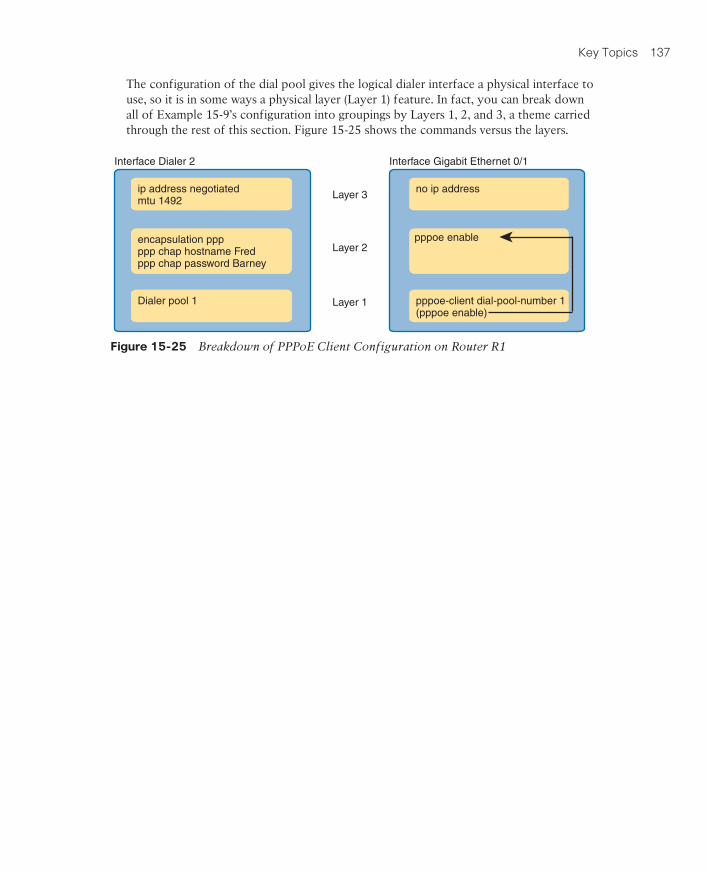
Key Topics 137
The configuration of the dial pool gives the logical dialer interface a physical interface to use, so it is in some ways a physical layer (Layer 1) feature. In fact, you can break down all of Example 15-9’s configuration into groupings by Layers 1, 2, and 3, a theme carried through the rest of this section. Figure 15-25 shows the commands versus the layers.
Interface Dialer 2
Layer 3
Layer 2
Layer 1
Interface Gigabit Ethernet 0/1
ip address negotiatedmtu 1492
no ip address
encapsulation pppppp chap hostname Fredppp chap password Barney
Dialer pool 1 pppoe-client dial-pool-number 1(pppoe enable)
pppoe enable
Figure 15-25 Breakdown of PPPoE Client Configuration on Router R1

138 CCNA Routing and Switching ICND2 200-105 Official Cert Guide
While PPPoE configuration has enough detail to be a challenge, PPPoE verification has a few more challenges because of how PPPoE works internally in IOS. Before reviewing a bunch of command output, it helps to get an idea about those internals. So, consider the ideas in Figure 15-26. The figure shows the two familiar interfaces from the configuration section, namely, a dialer interface and Ethernet interface. It adds two boxes for discussion:
PPPoE Session: A reference to the IOS internal process that performs the PPPoE work and keeps status variables for the PPPoE control protocols
Virtual-Access Interface: Another logical interface, dynamically created by IOS once the PPPoE session is up and working, and bound to the dialer interface
Dialer Interface
Dial Pool #Bind
Up
PPP Config
pppoe enable
Bind
Virtual-AccessInterface
PPPoESession
Ethernet Interface
1
2
3
2
4
4
Figure 15-26 PPPoE Verification Concepts and Interfaces

Key Topics 139
The sections about PPPoE verification and troubleshooting show a lot of command exam-ples. This section summarizes a few suggestions for what to look for to help with review and exam preparation.
Layer 1: If the show pppoe session [interface type number] command does not list out-put, or does not list both the physical and dialer interfaces, check for the existence of the Layer 1 commands as noted in Figure 15-28. Check for errors in those commands as well; for instance, the dial pool numbers must match. Also check to make sure both the dialer and physical interfaces are not shut down. (See Example 15-16.)
Layer 2: If the show pppoe session [interface type number] command does list output, and lists the physical and dialer interfaces, but no Vi interface, check the Layer 2 configu-ration as noted in Figure 15-28. Those could be missing, or there could be mistakes. For instance, something as simple as a mistyped CHAP password ends with this result. (See Example 15-17.)
Layer 2: If the show interfaces dialer number command lists an interface status (the first status value) of up (spoofing), that is another confirmation that PPPoE is not yet working. If so, check the PPP configuration on the dialer interface, and confirm the username/pass-word matches with what the ISP requires. (See Example 15-18.)
Layer 2: To be confident PPPoE is working, look for three items, all seen in Example 15-18’s show pppoe session command output:
■ A status of UP
■ Three interfaces listed in shorthand: the Ethernet interface (Gi0/1 in the example), the dialer interface (Di2), and the virtual-access interface (Vi1)
■ The MAC addresses of the two routers; check the local MAC address with a show
interfaces command on the local router
Layer 3: If the show interfaces or show ip interface brief command does not list an IP address for the dialer interface, then look for missing or incorrect Layer 3 commands per Figure 15-28.

140 CCNA Routing and Switching ICND2 200-105 Official Cert Guide
Here are a couple of possible false positives to avoid as well:
Dialer interface status: If the show interfaces dialer number command lists a protocol status (the second status value) of up (spoofing), do not be concerned. It will always list that status, both when working and not working. (See Example 15-18.)
Physical interface IP address: The physical Ethernet interface will not have an IP address. It is used to send Ethernet frames only. So, it is appropriate with PPPoE to configure the physical Ethernet interface with the no ip address command.

Key Topics 141
Chapter 16In short, to filter a packet, you must enable an ACL on an interface that processes the pack-et, in the same direction the packet flows through that interface.
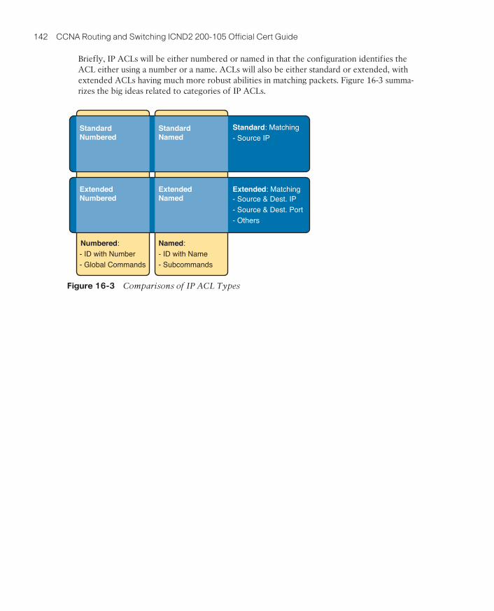
142 CCNA Routing and Switching ICND2 200-105 Official Cert Guide
Briefly, IP ACLs will be either numbered or named in that the configuration identifies the ACL either using a number or a name. ACLs will also be either standard or extended, with extended ACLs having much more robust abilities in matching packets. Figure 16-3 summa-rizes the big ideas related to categories of IP ACLs.
Numbered:- ID with Number- Global Commands
Named:- ID with Name- Subcommands
Extended: Matching- Source & Dest. IP- Source & Dest. Port- Others
Standard: Matching- Source IP
ExtendedNumbered
ExtendedNamed
StandardNumbered
StandardNamed
Figure 16-3 Comparisons of IP ACL Types

Key Topics 143
When doing ACL processing, the router processes the packet, compared to the ACL, as fol-lows:
ACLs use first-match logic. Once a packet matches one line in the ACL, the router takes the action listed in that line of the ACL, and stops looking further in the ACL.

144 CCNA Routing and Switching ICND2 200-105 Official Cert Guide
You can think about WC masks in decimal and in binary, and both have their uses. To begin, think about WC masks in decimal, using these rules:
Decimal 0: The router must compare this octet as normal.
Decimal 255: The router ignores this octet, considering it to already match.

Key Topics 145
In many cases, an ACL needs to match all hosts in a particular subnet. To match a subnet with an ACL, you can use the following shortcut:
■ Use the subnet number as the source value in the access-list command.
■ Use a wildcard mask found by subtracting the subnet mask from 255.255.255.255.

146 CCNA Routing and Switching ICND2 200-105 Official Cert Guide
This chapter has already introduced all the configuration steps in bits and pieces. This sec-tion summarizes those pieces as a configuration process. The process also refers to the access-list command, whose generic syntax is repeated here for reference:
access-list access-list-number {deny | permit} source [source-wildcard]
Step 1. Plan the location (router and interface) and direction (in or out) on that inter-face:
A. Standard ACLs should be placed near to the destination of the packets so that they do not unintentionally discard packets that should not be discarded.
B. Because standard ACLs can only match a packet’s source IP address, identify the source IP addresses of packets as they go in the direction that the ACL is examining.
Step 2. Configure one or more access-list global configuration commands to create the ACL, keeping the following in mind:
A. The list is searched sequentially, using first-match logic.
B. The default action, if a packet does not match any of the access-list commands, is to deny (discard) the packet.
Step 3. Enable the ACL on the chosen router interface, in the correct direction, using the ip access-group number {in | out} interface subcommand.

Key Topics 147
First, the following list summarizes some important tips to consider when choosing match-ing parameters to any access-list command:
■ To match a specific address, just list the address.
■ To match any and all addresses, use the any keyword.
■ To match based only on the first one, two, or three octets of an address, use the 0.255.255.255, 0.0.255.255, and 0.0.0.255 WC masks, respectively. Also, make the source (address) parameter have 0s in the wildcard octets (those octets with 255 in the wildcard mask).
■ To match a subnet, use the subnet ID as the source, and find the WC mask by subtract-ing the DDN subnet mask from 255.255.255.255.

148 CCNA Routing and Switching ICND2 200-105 Official Cert Guide
Chapter 17IOS requires that you configure parameters for the three highlighted parts of Figure 17-2. For the protocol type, you simply use a keyword, such as tcp, udp, or icmp, matching IP packets that happen to have a TCP, UDP, or ICMP header, respectively, following the IP header. Or you can use the keyword ip, which means “all IPv4 packets.” You also must con-figure some values for the source and destination IP address fields that follow; these fields use the same syntax and options for matching the IP addresses as discussed in Chapter 16, “Basic IPv4 Access Control Lists.” Figure 17-3 shows the syntax.
Keyword Address & Wildcard
100 - 1992000 - 2699 Matching
Options
access-list 101 permit source_IPprotocol dest_IP
iptcpudpicmpothers...
Figure 17-3 Extended ACL Syntax, with Required Fields

Key Topics 149
In an extended ACL access-list command, all the matching parameters must match the packet for the packet to match the command.

150 CCNA Routing and Switching ICND2 200-105 Official Cert Guide
The most useful ports to check are the well-known ports used by servers. For example, web servers use well-known port 80 by default. Figure 17-4 shows the location of the port num-bers in the TCP header, following the IP header.
IP Header TCP Header
MiscellaneousHeaderFields
Protocol6 (TCP)
HeaderChecksum
Source IPAddress
Destination IPAddress
OptionsSource
PortDest.Port
Restof
TCP
9 1 2 4 4 Variable 2 2 16+
6 = TCP
Figure 17-4 IP Header, Followed by a TCP Header and Port Number Fields

Key Topics 151
When an extended ACL command includes either the tcp or udp keyword, that command can optionally reference the source and/or destination port. To make these comparisons, the syntax uses keywords for equal, not equal, less than, greater than, and for a range of port numbers. In addition, the command can use either the literal decimal port numbers, or more convenient keywords for some well-known application ports. Figure 17-5 shows the positions of the source and destination port fields in the access-list command and these port number keywords.
access-list 101 permit source_IP dest_IPprotocol
Matchingsource_port dest_port
tcpudp
eq __ne __lt __gt __range __
eq __ne __lt __gt __range __
eq: lt: = < range: x to yne: gt: >Legend:
Figure 17-5 Extended ACL Syntax with Port Numbers Enabled Using Protocol TCP or UDP

152 CCNA Routing and Switching ICND2 200-105 Official Cert Guide
Conversely, Figure 17-7 shows the reverse flow, with a packet sent by the server back toward PC1. In this case, the packet’s TCP header has a source port of 21, so the ACL must check the source port value of 21, and the ACL must be located on different interfaces. In this case, the eq 21 parameters follow the source address field, but come before the desti-nation address field.
access-list 101 permit tcp 172.16.3.0 0.0.0.255 eq 21 172.16.1.0 0.0.0.255
Source 172.16.3.1 Destination 172.16.1.1 Source Port 21 Destination Port > 1023
R1 R2
172.16.1.0/24 172.16.3.0/24
172.16.3.1
Source AddressSource Port
Destination Address
Port 21
PC1IN
S0/0Fa0/0
OUTIN
S0/1 Fa0/0
OUT
Figure 17-7 Filtering Packets Based on Source Port

Key Topics 153
The configuration process for extended ACLs mostly matches the same process used for standard ACLs. You must choose the location and direction in which to enable the ACL, particularly the direction, so that you can characterize whether certain addresses and ports will be either the source or destination. Configure the ACL using access-list commands, and when complete, then enable the ACL using the same ip access-group command used with standard ACLs. All these steps mirror what you do with standard ACLs; however, when configuring, keep the following differences in mind:
■ Place extended ACLs as close as possible to the source of the packets that will be fil-tered. Filtering close to the source of the packets saves some bandwidth.
■ Remember that all fields in one access-list command must match a packet for the packet to be considered to match that access-list statement.
■ Use numbers of 100–199 and 2000–2699 on the access-list commands; no one number is inherently better than another.

154 CCNA Routing and Switching ICND2 200-105 Official Cert Guide
There are differences between named and numbered ACLs. Named ACLs originally had three big differences compared to numbered ACLs:
■ Using names instead of numbers to identify the ACL, making it easier to remember the reason for the ACL
■ Using ACL subcommands, not global commands, to define the action and matching parameters
■ Using ACL editing features that allow the CLI user to delete individual lines from the ACL and insert new lines

Key Topics 155
The ACL editing feature uses an ACL sequence number that is added to each ACL permit or deny statement, with the numbers representing the sequence of statements in the ACL. ACL sequence numbers provide the following features for both numbered and named ACLs:
New configuration style for numbered: Numbered ACLs use a configuration style like named ACLs, as well as the traditional style, for the same ACL; the new style is required to perform advanced ACL editing.
Deleting single lines: An individual ACL permit or deny statement can be deleted with a no sequence-number subcommand.
Inserting new lines: Newly added permit and deny commands can be configured with a sequence number before the deny or permit command, dictating the location of the statement within the ACL.
Automatic sequence numbering: IOS adds sequence numbers to commands as you con-figure them, even if you do not include the sequence numbers.

156 CCNA Routing and Switching ICND2 200-105 Official Cert Guide
ACLs can be a great tool to enhance the security of a network, but engineers should think about some broader issues before simply configuring an ACL to fix a problem. To help, Cisco makes the following general recommendations in the courses on which the CCNA R&S exams are based:
■ Place extended ACLs as close as possible to the source of the packet. This strategy allows ACLs to discard the packets early.
■ Place standard ACLs as close as possible to the destination of the packet. This strategy avoids the mistake with standard ACLs (which match the source IPv4 address only) of unintentionally discarding packets that did not need to be discarded.
■ Place more specific statements early in the ACL.
■ Disable an ACL from its interface (using the no ip access-group interface subcommand) before making changes to the ACL.

Key Topics 157
The following phrases the ACL troubleshooting steps into a list for easier study. The list also expands on the idea of analyzing each ACL in Step 3. None of the ideas in the list are new compared to this chapter and the previous chapter, but it acts more as a summary of the common issues:
Step 1. Determine on which interfaces ACLs are enabled, and in which direction (show
running-config, show ip interfaces).
Step 2. Find the configuration of each ACL (show access-lists, show ip access-lists,
show running-config).
Step 3. Analyze the ACLs to predict which packets should match the ACL, focusing on the following points:
A. Misordered ACLs: Look for mis-ordered ACL statements. IOS uses first-match logic when searching an ACL.
B. Reversed source/destination addresses: Analyze the router interface, the direction in which the ACL is enabled, compared to the location of the IP address ranges matched by the ACL statements. Make sure the source IP address field could match packets with that source IP address, rather than the destination, and vice versa for the destination IP address field.
C. Reversed source/destination ports: For extended ACLs that reference UDP or TCP port numbers, continue to analyze the location and direc-tion of the ACL versus the hosts, focusing on which host acts as server using a well known port. Ensure that the ACL statement matches the correct source or destination port depending on whether the server sent or will receive the packet.
D. Syntax: Remember that extended ACL commands must use the tcp and udp keywords if the command needs to check the port numbers.
E. Syntax: Note that ICMP packets do not use UDP or TCP; ICMP is considered to be another protocol matchable with the icmp keyword (instead of tcp or udp).
F. Explicit deny any: Instead of using the implicit deny any at the end of each ACL, use an explicit configuration command to deny all traffic at the end of the ACL so that the show command counters increment when that action is taken.
G. Dangerous inbound ACLs: Watch for inbound ACLs, especially those with deny all logic at the end of the ACL. These ACLs may discard incoming overhead protocols, like routing protocol messages.
H. Standard ACL location: Standard ACLs enabled close to the source of matched addresses can discard the packets as intended, but also discard packets that should be allowed through. Always pay close attention to the requirements of the ACL in these cases.

158 CCNA Routing and Switching ICND2 200-105 Official Cert Guide
Routers bypass their own outbound ACLs for packets generated by the router, as shown in Figure 17-13. Even thought ACL A exists as an outgoing ACL on Router R1, R1 bypasses its own outgoing ACL logic of ACL A for the ICMP Echo Requests generated by R1.
S0/0/0 G0/2S0/0/1G0/1R1 R2
S1
H1
H2
SW1
A AAB
CD
ping S1 -ignore ACL A
Figure 17-13 R1 Ignores Outgoing ACL for Packets Created by Its Own ping Command

Key Topics 159
Chapter 18Cisco offers a wide range of QoS tools on both routers and switches. All these tools give you the means to manage four characteristics of network traffic:
■ Bandwidth
■ Delay
■ Jitter
■ Loss

160 CCNA Routing and Switching ICND2 200-105 Official Cert Guide
You can achieve good-quality voice traffic over an IP network, but you must implement QoS to do so. QoS tools set about to give different types of traffic the QoS behavior they need. Cisco’s Enterprise QoS Solution Reference Network Design Guide, which itself quotes other sources in addition to relying on Cisco’s long experience in implementing QoS, suggests the following guidelines for interactive voice:
■ Delay (one-way): 150 ms or less
■ Jitter: 30 ms or less
■ Loss: 1% or less

Key Topics 161
Video has a much more varied set of QoS requirements. Generally, think of video like voice, but with a much higher bandwidth requirement than voice (per flow), and similar requirements for low delay, jitter, and loss. As for bandwidth, video can use a variety of codecs that impact the amount of data sent, but many other technical features impact the amount of bandwidth required for a single video flow. (For instance, a sporting event with lots of movement on screen takes more bandwidth than a news anchor reading the news in front of a solid background with little movement.) This time quoting from End-to-End QoS Network Design, Second Edition (Cisco Press, 2013), some requirements for video include
■ Bandwidth: 384 Kbps to 20+ Mbps
■ Delay (one-way): 200–400 ms
■ Jitter: 30–50 ms
■ Loss: 0.1%–1%

162 CCNA Routing and Switching ICND2 200-105 Official Cert Guide
IPv4 defines a Type of Service (ToS) byte in the IPv4 header, as shown in Figure 18-6. The original RFC defined a 3-bit IP Precedence (IPP) field for QoS marking. That field gave us eight separate values—binary 000, 001, 010, and so on, through 111—which when convert-ed to decimal are decimal 0 through 7.
DSCP ECN
RFC 2474 RFC 3168
IPP
RFC 791
Unused
Current Use
Old Use
Type ofService
(Rest of IP Header...)
IP Header
Figure 18-6 IP Precedence and Differentiated Services Code Point Fields
NOTE Those last 5 bits of the ToS byte per RFC 791 were mostly defined for some pur-pose, but were not used in practice to any significant extent.
While a great idea, IPP gave us only eight different values to mark, so later RFCs redefined the ToS byte with the DSCP field. DSCP increased the number of marking bits to 6 bits, allowing for 64 unique values that can be marked. The DiffServ RFCs, which became RFCs back in the late 1990s, have become accepted as the most common method to use when doing QoS, and using the DSCP field for marking has become quite common.

Key Topics 163
Another useful marking field exists in the 802.1Q header, in a field originally defined by the IEEE 802.1p standard. This field sits in the third byte of the 4-byte 802.1Q header, as a 3-bit field, supplying eight possible values to mark (see Figure 18-7). It goes by two differ-ent names: Class of Service, or CoS, and Priority Code Point, or PCP.
802.1 QEthernet
Class of Service (CoS) (3 Bits)Priority Code Point (PCP)
Type Data Trailer
Ethernet Frame
Figure 18-7 Class of Service Field in 802.1Q/p Header

164 CCNA Routing and Switching ICND2 200-105 Official Cert Guide
Interestingly, when the access layer includes an IP Phone, the phone is typically the trust boundary, instead of the access layer switch. IP Phones can set the CoS and DSCP fields of the messages created by the phone, as well as those forwarded from the PC through the phone. The specific marking values are actually configured on the attached access switch. Figure 18-10 shows the typical trust boundary in this case, with notation of what the phone’s marking logic usually is: mark all of the PC’s traffic with a particular DSCP and/or CoS, and the phone’s traffic with different values.
Set PC DSCP and CoSSet Phone DSCP and CoS
WAN
Trust Boundary
…SW1 SW2 R1 R2IP
Figure 18-10 Trusting Devices—IP Phone

Key Topics 165
Next, think a little more deeply about the queuing system. Most networking devices can have a queuing system with multiple queues. To use multiple queues, the queuing system needs a classifier function to choose which packets are placed into which queue. (The clas-sifier can react to previously marked values, or do a more extensive match.) The queuing system needs a scheduler as well, to decide which message to take next when the interface becomes available, as shown in Figure 18-14.
Classifier
Transmit
Queues Scheduler
Figure 18-14 Congestion Management (Queuing) Components

166 CCNA Routing and Switching ICND2 200-105 Official Cert Guide
The solution, LLQ, tells the scheduler to treat one or more queues as special priority queues. The LLQ scheduler always takes the next message from one of these special prior-ity queues. Problem solved: very little delay for packets in that queue, resulting in very little jitter as well. Plus the queue never has time to fill up, so there are no drops due to the queue filling up. Figure 18-17 shows the addition of the LLQ logic for the voice queue.
Classifier
Transmit
SchedulerLLQ—Always Next
Round Robin
data 1
data 2
default
voice
Figure 18-17 LLQ Always Schedules Voice Packet Next

Key Topics 167
This section about queuing introduces several connected ideas, so before leaving the discus-sion of queuing, think about this strategy for how most enterprises approach queuing in their QoS plans:
1. Use a round robin queuing method like CBWFQ for data classes and for noninterac-tive voice and video.
2. If faced with too little bandwidth compared to the typical amount of traffic, give data classes that support business-critical applications much more guaranteed bandwidth than is given to less important data classes.
3. Use a priority queue with LLQ scheduling for interactive voice and video, to achieve low delay, jitter, and loss.
4. Put voice in a separate queue from video, so that the policing function applies sepa-rately to each.
5. Define enough bandwidth for each priority queue so that the built-in policer should not discard any messages from the priority queues.
6. Use Call Admission Control (CAC) tools to avoid adding too much voice or video to the network, which would trigger the policer function.

168 CCNA Routing and Switching ICND2 200-105 Official Cert Guide
Shapers and policers monitor the traffic rate (the bits/second that move through the shaper or policer) versus a configured shaping rate or policing rate, respectively. The basic question that both ask is listed below, with the actions based on the answers:
1. Does this next packet push the measured rate past the configured shaping rate or policing rate?
2. If no:
a. Let the packet keep moving through the normal path and do nothing extra to the packet.
3. If yes:
a. If shaping, delay the message by queuing it.
b. If policing, either discard the message or mark it differently.

Key Topics 169
Summarizing the key features of policing:
■ It measures the traffic rate over time for comparison to the configured policing rate.
■ It allows for a burst of data after a period of inactivity.
■ It is enabled on an interface, in either direction, but typically at ingress.
■ It can discard excess messages, but can also re-mark the message so that it is a candidate for more aggressive discard later in its journey.

170 CCNA Routing and Switching ICND2 200-105 Official Cert Guide
Summarizing the key features of shapers:
■ Shapers measure the traffic rate over time for comparison to the configured shaping rate.
■ Shapers allow for bursting after a period of inactivity.
■ Shapers are enabled on an interface for egress (outgoing packets).
■ Shapers slow down packets by queuing them, and over time releasing them from the queue at the shaping rate.
■ Shapers use queuing tools to create and schedule the shaping queues, which is very important for the same reasons discussed for output queuing.

Key Topics 171
Chapter 19The ROAS configuration creates a subinterface for each VLAN on the trunk, and the router then treats all frames tagged with that associated VLAN ID as if they came in or out of that subinterface. Figure 19-2 shows the concept with Router B1, one of the branch routers from Figure 19-1. Because this router needs to route between only two VLANs, the figure also shows two subinterfaces, named G0/0.10 and G0/0.20, which create a new place in the configuration where the per-VLAN configuration settings can be made. The router treats frames tagged with VLAN 10 as if they came in or out of G0/0.10, and frames tagged with VLAN 20 as if they came in or out G0/0.20.
10.1.20.1/24
10.1.10.1/24
Interface G0/0.10
Interface G0/0.20
VLAN 20
VLAN 10
20 10 20 10 20
SW1B1
Figure 19-2 Subinterfaces on Router B1

172 CCNA Routing and Switching ICND2 200-105 Official Cert Guide
The configuration and use of the native VLAN on the trunk requires a little extra thought. The native VLAN can be configured on a subinterface, or on the physical interface, or ignored as in Example 19-1. Each 802.1Q trunk has one native VLAN, and if the router needs to route packets for a subnet that exists in the native VLAN, then the router needs some configuration to support that subnet. The two options to define a router interface for the native VLAN are
■ Configure the ip address command on the physical interface, but without an encapsulation command; the router considers this physical interface to be using the native VLAN.
■ Configure the ip address command on a subinterface, and use the encapsulation dot1q
vlan-id native subcommand to tell the router both the VLAN ID and the fact that it is the native VLAN.

Key Topics 173
First, to check ROAS on the router, you need to start with the intended configuration, and ask questions about the configuration:
1. Is each non-native VLAN configured on the router with an encapsulation dot1q vlan-id command on a subinterface?
2. Do those same VLANs exist on the trunk on the neighboring switch (show interfaces
trunk), and are they in the allowed list, not VTP pruned, and not STP blocked?
3. Does each router ROAS subinterface have an IP address/mask configured per the planned configuration?
4. If using the native VLAN, is it configured correctly on the router either on a subinter-face (with an encapsulation dot1q vlan-id native command) or implied on the physi-cal interface?
5. Is the same native VLAN configured on the neighboring switch’s trunk?
6. Are the router physical or ROAS subinterfaces configured with a shutdown com-mand?

174 CCNA Routing and Switching ICND2 200-105 Official Cert Guide
To show the concept of Layer 3 switching with SVIs, Figure 19-3 shows the design changes and configuration concept for the same branch office used in Figures 19-1 and 19-2. The figure shows the Layer 3 switch function with a router icon inside the switch, to emphasize that the switch routes the packets. The branch still has two user VLANs, so the Layer 3 switch needs one VLAN interface for each VLAN. In addition, the traffic still needs to get to the router to access the WAN, so the switch uses a third VLAN (VLAN 30 in this case) for the link to Router B1. This link would not be a trunk, but would be an access link.
VLAN 20
interface vlan 2010.1.20.1/24
interface vlan 1010.1.10.1/24
VLAN 10VLAN 30
interface vlan 3010.1.30.1/24G0/0
10.1.30.2B1
The Middle Box Represents the Layer 3 Switch,with Internal Logic Visible
G0/1
F0/1
F0/2
F0/3
F0/4
Figure 19-3 Routing on VLAN Interfaces in a Layer 3 Switch

Key Topics 175
The second big area to investigate when troubleshooting SVIs relates to the SVI state, a state that ties to the state of the associated VLANs. Each VLAN interface has a matching VLAN of the same number, and the VLAN interface’s state is tied to the state of the VLAN in certain ways. In particular, for a VLAN interface to be in an up/up state:
Step 1. The VLAN must be defined on the local switch (either explicitly, or learned with VTP).
Step 2. The switch must have at least one up/up interface using the VLAN, either/both:
A. An up/up access interface assigned to that VLAN
B. A trunk interface for which the VLAN is in the allowed list, is STP for-warding, and is not VTP pruned
Step 3. The VLAN (not the VLAN interface) must be administratively enabled (that is, not shutdown).
Step 4. The VLAN interface (not the VLAN) must be administratively enabled (that is, not shutdown).

176 CCNA Routing and Switching ICND2 200-105 Official Cert Guide
To see why, consider the design in Figure 19-4, which repeats the same design from Figure 19-3 (used in the SVI examples). In that familiar design, at least two access ports sit in both VLAN 10 and VLAN 20. However, that figure shows a single link from the switch to Router B1. As a result, the switch could configure that link as a routed port.
VLAN 20
interface vlan 2010.1.20.1/24
interface vlan 1010.1.10.1/24
VLAN 10
VLAN 30
interface G0/110.1.30.1/24
G0/010.1.30.2
B1
The Middle Box Represents the Layer 3 Switch
F0/1
F0/2
F0/3
F0/4
RoutedInterface
Figure 19-4 Routing on a Routed Interface on a Switch

Key Topics 177
Once configured, the routed interface will show up differently in command output in the switch. In particular, for an interface configured as a routed port with an IP address, like interface GigabitEthernet0/1 in the previous example:
show interfaces: Similar to the same command on a router, the output will display the IP address of the interface. (For switch ports, this command does not list an IP address.)
show interfaces status: Under the “VLAN” heading, instead of listing the access VLAN or the word “trunk,” the output lists the word “routed,” meaning that it is a routed port.
show ip route: Lists the routed port as an outgoing interface in routes.
show interfaces type number switchport: If a routed port, the output is short and con-firms that the port is not a switch port. (If the port is a Layer 2 port, this command lists many configuration and status details.)

178 CCNA Routing and Switching ICND2 200-105 Official Cert Guide
NOTE Cisco uses the term EtherChannel in concepts discussed in this section, and then uses the term port channel, with command keyword port-channel, when verifying and con-figuring EtherChannels. For the purposes of understanding the technology, you may treat these terms as synonyms. However, it helps to pay close attention to the use of the terms port channel and EtherChannel as you work through the examples in this section, because IOS uses both.
Example 19-12 shows an example of the configuration for a Layer 3 EtherChannel for switch SW1 in Figure 19-7. The EtherChannel defines a port-channel interface 12, and uses subnet 10.1.12.0/24.
VLAN 3Subnet 10.1.3.0/24
VLAN 2Subnet 10.1.2.0/24
Fa0/23
Fa0/24
Fa0/22
Fa0/21
Po12 Po12
interface port-channel 12 ip address 10.1.12.1 255.255.255.0 no switchport
Subnet 10.1.12.0/24
interface port-channel 12 ip address 10.1.12.2 255.255.255.0 no switchport
SW1 SW2
G1/0/13
G1/0/14
G1/0/13
G1/0/14
Figure 19-7 Design Used in EtherChannel Configuration Examples

Key Topics 179
Additionally, you must do more than just configure the channel-group command correctly for all the physical ports to be bundled into the EtherChannel. Layer 2 EtherChannels have a longer list of requirements, but Layer 3 EtherChannels do require a few consistency checks between the ports before they can be added to the EtherChannel. The following is the list of requirements for Layer 3 EtherChannels:
no switchport: The port-channel interface must be configured with the no switch-
port command, and so must the physical interfaces. If a physical interface is not also configured with the no switchport command, it will not become operational in the EtherChannel.
Speed: The physical ports in the channel must use the same speed.
duplex: The physical ports in the channel must use the same duplex.

180 CCNA Routing and Switching ICND2 200-105 Official Cert Guide
Chapter 20To allow the hosts to remain unchanged, the routers have to do some more work, as defined by one of the FHRP protocols. Generically, each FHRP makes the following happen:
1. All hosts act like they always have, with one default router setting that never has to change.
2. The default routers share a virtual IP address in the subnet, defined by the FHRP.
3. Hosts use the FHRP virtual IP address as their default router address.
4. The routers exchange FHRP protocol messages, so that both agree as to which router does what work at any point in time.
5. When a router fails, or has some other problem, the routers use the FHRP to choose which router takes over responsibilities from the failed router.

Key Topics 181
Hosts refer to the virtual IP address as their default router address, instead of any one router’s interface IP address. For instance, in Figure 20-5, R1 and R2 use HSRP. The HSRP virtual IP address is 10.1.1.1, with the virtual MAC address referenced as VMAC1 for sim-plicity’s sake.
R1 R3
R2 R4
AGW=.1
HSRP
Subnet 10.1.1.0/24
.1VMAC1
BGW=.1
CGW=.1
DGW=.1
IP10.1.1.1
Host ARP Table
HSRP Standby
HSRP Active
MACVMAC1
Figure 20-5 All Traffic Goes to .1 (R1, Which Is Active); R2 Is Standby

182 CCNA Routing and Switching ICND2 200-105 Official Cert Guide
Figure 20-6 shows the result when R1, the HSRP active router in Figure 20-5, fails. R1 quits using the virtual IP and MAC address, while R2, the new active router, starts using these addresses. The hosts do not need to change their default router settings at all, with traffic now flowing to R2 instead of R1.
R1 R3
R2 R4
AGW=.1
IP10.1.1.1
Host ARP Table
.1
.9
.1
.129
No Change
VMAC1
VMAC1
HSRP Active
BGW=.1
CGW=.1
DGW=.1
No ChangeMACVMAC1
Figure 20-6 Packets Sent Through R2 (New Active) Once It Takes Over for Failed R1

Key Topics 183
Each line of output lists the local router’s view of the HSRP status for that group. In particu-lar, based on the headings, the show standby brief command identifies the following:
Interface: The local router’s interface on which the HSRP group is configured
Grp: The HSRP group number
Pri: The local router’s HSRP priority
State: The local router’s current HSRP state
Active: The interface IP address of the currently active HSRP router (or “local” if the local router is HSRP active)
Standby: The interface IP address of the currently standby HSRP router (or “local” if the local router is HSRP standby)
Virtual IP: The virtual IP address defined by this router for this group

184 CCNA Routing and Switching ICND2 200-105 Official Cert Guide
First, the HSRP rules. When a router (call it the local router) has an HSRP-enabled interface, and that interface comes up, the router sends HSRP messages to negotiate whether it should be active or standby. When it sends those messages, if it…
Step 1. …discovers no other HSRP routers in the subnet, the local router becomes the active router.
Step 2. …discovers an existing HSRP router, and both are currently negotiating to decide which should become the HSRP active router, the routers negotiate, with the router with the highest HSRP priority becoming the HSRP active router.
Step 3. …discovers an existing HSRP router in the subnet, and that router is already acting as the active router:
A. If configured with no preemption (the default; no standby preempt), the local router becomes a standby router, even if it has a better (higher) priority.
B. If configured with preemption (standby preempt), the local router checks its priority versus the active router; if the local router priority is better (higher), the local router takes over (preempts) the existing active router to become the new active HSRP router.

Key Topics 185
Beyond IPv6 support and shorter Hello timer options, other differences for version 2 versus version 1 include a different virtual MAC address base value and a different multicast IP address used as the destination for all messages. Table 20-3 lists the differences between HSRPv1 and HSRPv2.
Table 20-3 HSRPv1 Versus HSRPv2
Feature Version 1 Version 2
IPv6 support No Yes
Smallest unit for Hello timer Second Millisecond
Range of group numbers 0..255 0..4095
MAC address used (xx or xxx is the hex group number) 0000.0C07.ACxx 0000.0C9F.Fxxx
IPv4 multicast address used 224.0.0.2 224.0.0.102
Does protocol use a unique identifier for each router? No Yes

186 CCNA Routing and Switching ICND2 200-105 Official Cert Guide
Next, for HSRP to work correctly, some of the HSRP parameters must match. For instance, if two routers were intended to be in the same HSRP group, but were configured with two different HSRP versions, they would not understand each other’s messages, and would ignore each other, and would act independently from each other. The following list details some important items to check to make sure the configurations should work:
■ Routers must be configured with the same HSRP version (standby version {1 | 2})
■ Routers must be configured with the same HSRP group number (standby number …).
■ Routers must configure the same virtual IP address (standby number ip address).
■ Virtual IP address must be (a) in the same subnet as the interface IP address and (b) not used by any other device in the subnet (including the other HSRP routers) (standby number ip address).
■ In the attached Layer 2 network, the interfaces on the routers or Layer 3 switches must be in the same VLAN.
■ No ACLs should filter HSRP messages between the two routers. (HSRP uses UDP, port 1985; version 1 sends to multicast address 224.0.0.2, while version 2 sends to 224.0.0.102.)

Key Topics 187
IOS cannot detect several configuration mistakes that vary from the good configuration suggestions in the previous list. So, think about what a good configuration would look like, and then imagine purposefully misconfiguring a single item. What would the symptoms be? Table 20-4 lists four such purposeful configuration mistakes. Each assumes that only one mistake is made. Following the table, the chapter takes a closer look at each.
Table 20-4 HSRP Misconfiguration Scenarios and Expected Results
Reference Number
Scenario Routers Both Become Active?
Duplicate Address Detected?
VIP Changes Depending on Active Router?
1 HSRP version mismatch Yes Yes N/A
2 HSRP group number mismatch
Yes Yes N/A
3 ACL blocks HSRP packets Yes No N/A
4 Routers configure different VIPs
No N/A Yes

188 CCNA Routing and Switching ICND2 200-105 Official Cert Guide
Chapter 21
DNS1Address
DNS2Address
G0/0
Address
DNS
A
R1
1
Default Router2
MaskMask
Math Math
34
Address + Mask
Subnet ID &Address Range
4
Figure 21-2 Host IPv4 Settings Compared to What the Settings Should Match
As numbered in the figure, these steps should be followed to check the host’s IPv4 settings:
Step 1. Check the host’s list of DNS server addresses against the actual addresses used by those servers.
Step 2. Check the host’s default router setting against the router’s LAN interface con-figuration, for the ip address command.
Step 3. Check the subnet mask used by the router and the host; if they use a different mask, the subnets will not exactly match, which will cause problems for some host addresses.
Step 4. The host and router should attach to the exact same subnet—same subnet ID and same range of IP addresses. So, use both the router’s and host’s IP address and mask, calculate the subnet ID and range of addresses, and confirm they are in the same subnet as the subnet implied by the address/mask of the router’s ip
address command.

Key Topics 189
This book does not go into much detail about how DNS truly works behind the scenes, but even with a basic analysis, two major types of potential DNS issues are obvious:
■ A user host (DNS client) that has an incorrect setting for the DNS server IP address(es)
■ An IP connectivity problem between the user’s host and the correct DNS server

190 CCNA Routing and Switching ICND2 200-105 Official Cert Guide
The following troubleshooting checklist gives us a place to start when troubleshooting DHCP-related issues:
Step 1. If using a centralized DHCP server, at least one router on each remote subnet that has DHCP clients must act as DHCP relay agent, and have a correctly con-figured ip helper-address address subcommand on the interface connected to that subnet.
Step 2. Troubleshoot for any IP connectivity issues between the DHCP relay agent and the DHCP server, using the relay agent interface IP address and the server IP address as the source and destination of the packets.
Step 3. Whether using a local DHCP server or centralized server, troubleshoot for any LAN issues between the DHCP client and the DHCP relay agent.
Step 4. Troubleshoot incorrect server configuration.

Key Topics 191
Router LAN interfaces can fail to reach a working up/up state for several reasons, including the common reasons listed in Table 21-1.
Table 21-1 Common Reasons Why Router LAN Interfaces Are Not Up/Up
Reason Description Router Interface State
Speed mismatch
The router and switch can both use the speed interface subcommand to set the speed, but to different speeds.
Down/down
Shutdown The router interface has been configured with the shutdown interface subcommand.
Admin down/down
Shutdown at switch
The neighboring switch interface has been configured with the shutdown interface subcommand, while the router interface is no shutdown.
Down/down
Err-disabled switch
The neighboring switch port uses port security, which has put the port in an err-disabled state.
Down/down
No cable/bad cable
The router has no cable installed, or the cable pinouts are incorrect.*
Down/down
* Cisco switches use a feature called auto-mdix, which automatically detects some incorrect cabling pinouts and internally changes the pin logic to allow the cable to be used. As a result, not all incorrect cable pinouts result in an interface failing.
192 CCNA Routing and Switching ICND2 200-105 Official Cert Guide
Now on to how a router matches the routing table, even with overlapping routes in its rout-ing table. If only one route matches a given packet, the router uses that one route. However, when more than one route matches a packet’s destination address, the router uses the “best” route, defined as follows:
When a particular destination IP address matches more than one route in a router’s IPv4 routing table, the router uses the most specific route—in other words, the route with the longest prefix length mask.

Key Topics 193
Figure 21-10 shows the output of a sample show ip route command. The figure numbers various parts of the command output for easier reference, with Table 21-3 describing the output noted by each number.
CLOO
10.0.0.0/8 is variably subnetted, 13 subnets, 5 masks
5 6 7 8 94
1 2 3
10 11
10.1.3.0/26 is directly connected, GigabitEthernet0/110.1.3.3/32 is directly connected, GigabitEthernet0/110.1.4.64/26 [110/65] via 10.2.2.10, 14:31:52, Serial0/1/010.2.2.0/30 [110/128] via 10.2.2.5, 14:31:52, Serial0/0/1
Figure 21-10 show ip route Command Output Reference
Table 21-3 Descriptions of the show ip route Command Output
Item Idea Value in the Figure
Description
1 Classful network
10.0.0.0/8 The routing table is organized by classful network. This line is the heading line for classful network 10.0.0.0; it lists the default mask for Class A networks (/8).
2 Number of subnets
13 subnets Lists the number of routes for subnets of the classful network known to this router, from all sources, including local routes—the /32 routes that match each router interface IP address.
3 Number of masks
5 masks The number of different masks used in all routes known to this router inside this classful network.
4 Legend code C, L, O A short code that identifies the source of the routing information. O is for OSPF, D for EIGRP, C for Connected, S for static, and L for local. (See Example 5-4 for a sample of the legend.)
5 Subnet ID 10.2.2.0 The subnet number of this particular route.
6 Prefix length /30 The prefix mask used with this subnet.
7 Administrative distance
110 If a router learns routes for the listed subnet from more than one source of routing information, the router uses the source with the lowest administrative distance (AD).
8 Metric 128 The metric for this route.
9 Next-hop router
10.2.2.5 For packets matching this route, the IP address of the next router to which the packet should be forwarded.
10 Timer 14:31:52 For OSPF and EIGRP routes, this is the time since the route was first learned.
11 Outgoing interface
Serial0/0/1 For packets matching this route, the interface out which the packet should be forwarded.

194 CCNA Routing and Switching ICND2 200-105 Official Cert Guide
IP subnetting rules require that the address ranges in the subnets used in an internetwork should not overlap. IOS sometimes can recognize when a new ip address command creates an overlapping subnet, but sometimes not, as follows:
■ Preventing the overlap on a single router: IOS detects the overlap when the ip address command implies an overlap with another ip address command on the same router.
■ Allowing the overlap on different routers: IOS cannot detect an overlap when an ip
address command overlaps with an ip address command on another router.

Key Topics 195
Chapter 22Table 22-1 summarizes a few bits of reference information about global unicast and unique local unicasts for reference.
Table 22-1 Summary of IPv6 Unicast Address Types
Type First Digits Similar to IPv4 Public or Private?
Global unicast 2 or 31 Public
Unique local unicast FD Private
Link-local FE80 N/A
1 IANA actually defi nes the global unicast address range as any address not otherwise reserved for some other purpose. However, actual address assignments normally happen from 2000::/3 because that was the original range used for these addresses. Many IPv6 references simply quote 2000::/3 as the prefi x, which means the fi rst hex digit is either a 2 or 3.

196 CCNA Routing and Switching ICND2 200-105 Official Cert Guide
The one noticeable difference between DHCPv4 and stateful DHCPv6 is that the stateful DHCPv6 server does not supply the default router information. Instead, a built-in protocol, NDP, lets the host ask the local routers to identify themselves. Otherwise, hosts use the same general process as with DHCPv4. Figure 22-5 shows a comparison of what is learned by a host using DHCPv4 and stateful DHCPv6.
Unicast Address
Prefix Length
DNS Servers
Stateful DHCPv6
Default Router
NDP
Unicast Address
Subnet Mask
DNS Servers
DHCPv4
Default Router
IPv4 IPv6
Figure 22-5 Sources of Specific IPv6 Settings When Using Stateful DHCP

Key Topics 197
SLAAC defines an overall process that also uses NDP and DHCPv6 with a stateless service; the server keeps no state information. First, the process takes advantage of NDP, through which the host can learn the following from any router on the link: the IPv6 prefix (subnet ID), the prefix length (mask equivalent), and the default router IPv6 address. The host uses SLAAC rules to build the rest of its address. Finally, the host uses stateless DHCPv6 to learn the DNS server IPv6 addresses. Figure 22-7 summarizes these details for easy study and ref-erence.
Prefix
Prefix Length
NDP
Unicast Address
SLAAC
Default Router
Stateless DHCPv6
DNS Servers
Figure 22-7 Sources of Specific IPv6 Settings When Using SLAAC

198 CCNA Routing and Switching ICND2 200-105 Official Cert Guide
If the host uses the EUI-64 option, the address built by the host can be predicted. The prefix part of the address is the prefix as defined on the local IPv6 router. Then, the host’s MAC address feeds into a few EUI-64 (also called modified EUI-64) rules to change the 48-bit MAC address into a 64-bit interface ID, as follows:
1. Split the 6-byte (12 hex digits) MAC address in two halves (6 hex digits each).
2. Insert FFFE in between the two, making the interface ID now have a total of 16 hex digits (64 bits).
3. Invert the seventh bit of the first byte.

Key Topics 199
Figure 22-8 shows the major pieces of how the address is formed.
Subnet Prefix1st Halfof MAC
FFFE 2nd Halfof MAC
Learned with NDP
Invert 7th Bit, 1st Byte(Reading Left to Right)
Calculated by Host
Figure 22-8 IPv6 Address Format with Interface ID and EUI-64

200 CCNA Routing and Switching ICND2 200-105 Official Cert Guide
Before getting into the specific scenarios, the following three lists break down some impor-tant facts that should be true about a working IPv6 network. Many of the root causes of problems in this section of the chapter happen because one of these rules was broken.
Host-Focused Issues
1. Hosts should be in the same IPv6 subnet as their default router.
2. Hosts should use the same prefix length as their default router.
3. Hosts should have a default router setting that points to a real router’s address.
4. Hosts should have correct Domain Name Service (DNS) server addresses.

Key Topics 201
Router-Focused Issues
1. Router interfaces in use should be in an up/up state.
2. Two routers that connect to the same data link should have addresses in the same IPv6 subnet.
3. Routers should have IPv6 routes to all IPv6 subnets as per the IPv6 subnet design.

202 CCNA Routing and Switching ICND2 200-105 Official Cert Guide
Filtering Issues
1. Watch for MAC address filtering on the LAN switches.
2. Watch for missing VLANs in switches.
3. Watch for IPv6 access control lists (ACL) in routers.

Key Topics 203
Figure 22-13 collects all the pieces that should match. The concepts mirror the same con-cepts in IPv4.
DNS1Address
DNS2Address
G0/0
Address
DNS
A
R1
1
Default Router2
Prefix LengthPrefix Length
Math Math
34
Address + Length
Prefix &Prefix Length
4
Figure 22-13 Host IPv6 Settings Compared to What the Settings Should Match
204 CCNA Routing and Switching ICND2 200-105 Official Cert Guide
To find the problem, the engineer needs to start thinking outside the IPv6 world and start thinking about the LAN between the host and the router. In particular, the probable root causes can be broken down into these categories:
1. The router or host LAN interface is administratively disabled.
2. The LAN has some problem that prevents the flow of Ethernet frames.
3. The LAN has filtering (for example, port security) that filters the Ethernet frames.

Key Topics 205
These symptoms pretty clearly point to “some kind of name resolution problem.” However, that does not define the specific root cause that the engineer can go fix to get the user working again. In this case, the root causes could fall into these categories:
1. An incorrect host DNS server setting, as statically defined on the host
2. An incorrect host DNS server setting, as learned with (stateless or stateful) DHCPv6
3. An IPv6 connectivity problem between the user’s host and the DNS server

206 CCNA Routing and Switching ICND2 200-105 Official Cert Guide
Stateful DHCP troubleshooting follows the same basic logic as for IPv4 DHCP, as discussed in Chapter 21, “Troubleshooting IPv4 Routing,” in the “DHCP Issues” section. So, a few concepts similar to that chapter, the following must be true for an IPv6 host to successfully use either stateful or stateless DHCPv6 to learn information from a DHCPv6 server:
1. The server must be in the same subnet as the client.
Or
2. The server may be in a different subnet, with
a. The router that sits on the same subnet as the client host correctly implementing DHCP relay
b. IPv6 connectivity working between that local router (the router near the client host) and the DHCPv6 server

Key Topics 207
The two most likely root causes of a host failing to dynamically learn its IPv6 settings with stateful DHCPv6 are root causes 2A and 2B. For 2A, the solution requires a configuration command on the correct interface on each LAN that is remote from the DHCPv6 server. For instance, in Figure 22-16, host D sits on a LAN subnet on the left, with R1’s G0/0 inter-face connected to the same subnet. R1 should have the command listed at the bottom of the figure to enable the IPv6 DHCP relay function pointing to the DHCPv6 server on the right.
BD
DHCPv6 Serveripv6 dhcp relay destination 2001:DB8:1111:3::8
G0/0 R1R2
S1
2001:DB8:1111:3::8
Figure 22-16 IPv6 DHCP Relay

208 CCNA Routing and Switching ICND2 200-105 Official Cert Guide
Hosts that use SLAAC rely on the information in the RA message. So, when a host fails to learn and build these three settings when using SLAAC, including the IPv6 address, the next question really should be this: What could cause the NDP RS/RA process to fail? The fol-lowing list details these potential root causes:
1. No LAN connectivity between the host and any router in the subnet.
2. The router is missing an ipv6 address interface subcommand.
3. The router is missing an ipv6 unicast-routing global configuration command.

Key Topics 209
Routing problems happen for many reasons. Some routing problems happen because routes are missing from a router (perhaps because of many specific root causes). Some routing problems happen because a router has an incorrect route. The following list gives just some of the reasons why a router might be missing a needed route or might have an incorrect route:
■ Links between routers are down.
■ Routing protocol neighbor problems exist.
■ Routing protocol route filtering prevents the route from being added to the IPv6 routing table.
■ Incorrect static routes send packets to the wrong next router.
■ Poor subnet design duplicates subnets in different locations in the network, falsely advertising a subnet.

210 CCNA Routing and Switching ICND2 200-105 Official Cert Guide
Chapter 23To the depth that this book discusses OSPF theory and concepts, OSPFv3 acts very much like OSPFv2. For example, both use link-state logic. Both use the same metric. And the list keeps getting longer, because the protocols do have many similarities. The following list notes many of the similarities for the features discussed both in this chapter and in Chapter 7, “Understanding OSPF Concepts”:
■ Both are link-state protocols.
■ Both use the same area design concepts and design terms.
■ Both require that the routing protocol be enabled on an interface.
■ Once enabled on an interface, both then attempt to discover neighbors connected to the data link connected to an interface.
■ Both perform a check of certain settings before a router will become neighbors with another router (the list of checks is slightly different between OSPFv2 and OSPFv3).
■ After two routers become neighbors, both OSPFv2 and OSPFv3 proceed by exchanging the contents of their LSDB—the link-state advertisements (LSA) that describe the net-work topology—between the two neighbors.
■ After all the LSAs have been exchanged, both OSPFv2 and OSPFv3 use the shortest path first (SPF) algorithm to calculate the best route to each subnet.
■ Both use the same metric concept, based on the interface cost of each interface, with the same default cost values.
■ Both use LSAs to describe the topology, with some differences in how LSAs work.

Key Topics 211
To be clear, nothing in R1’s configuration mentions multiarea or ABR—R1 simply acts as an ABR because its configuration puts some interfaces in area 0 and others in other nonback-bone areas. Example 23-4 shows the configuration.
Example 23-4 IPv6 and OSPFv3 Configuration on ABR R1
ipv6 unicast-routing
!
interface GigabitEthernet0/0
mac-address 0200.0000.0001
!
interface GigabitEthernet0/0.11
encapsulation dot1q 11
ipv6 address 2001:db8:1:1::1/64
ipv6 ospf 1 area 0
!
interface GigabitEthernet0/0.12
encapsulation dot1q 12
ipv6 address 2001:db8:1:2::1/64
ipv6 ospf 1 area 0
!
interface GigabitEthernet0/1
ipv6 address 2001:db8:1:14::1/64
ipv6 ospf 1 area 4
!
interface serial 0/0/0
ipv6 address 2001:db8:1:12::1/64
ipv6 ospf 1 area 23
!
interface serial 0/0/1
ipv6 address 2001:db8:1:13::1/64
ipv6 ospf 1 area 23
!
ipv6 router ospf 1
router-id 1.1.1.1

212 CCNA Routing and Switching ICND2 200-105 Official Cert Guide
To influence the metric for the route, OSPFv3 gives us a few ways to change an interface’s OSPFv3 cost, with the same basic rules as OSPFv2, as summarized in this list:
1. Set the cost explicitly using the ipv6 ospf cost x interface subcommand to a value between 1 and 65,535, inclusive.
2. Change the interface bandwidth with the bandwidth speed command, with speed being a number in kilobits per second (Kbps), and let the router calculate the value based on the OSPFv3 reference-bandwidth / interface-bandwidth.
3. Change the reference bandwidth with router OSPFv3 subcommand auto-cost
reference-bandwidth ref-bw, with a unit of megabits per second (Mbps).

Key Topics 213
To the depth discussed in these books, OSPFv3 works much like OSPFv2 with regard to
■ Area design and the related terms
■ The configuration idea of enabling the routing process, per interface, for an area
■ The neighbor discovery process with Hello messages
■ Transitioning through neighbor states and the topology exchange process
■ The use of full and 2-way as the normal stable state for working neighbor relationships, with other states being either temporary or pointing to some problem with the neighbor
■ SPF and how it uses interface cost to calculate metrics
■ Messages being sent to reserved multicast addresses (FF02::5 for all OSPF routers, FF02::6 for all DR and BDR routers), similar to OSPFv2’s use of 224.0.0.5 and 224.0.0.6
214 CCNA Routing and Switching ICND2 200-105 Official Cert Guide
So, what is different between OSPFv3 and OSPFv2? The next list mentions a few differ-ences. However, note that many of the differences happen to be outside the scope of the coverage of topics in this book.
■ OSPFv3 neighbors do not have to have IPv6 addresses in the same IPv6 subnet, whereas OSPFv2 neighbors must be in the same IPv4 subnet.
■ They use different names for their Type 3 LSAs (called inter-area prefix LSAs in OSPFv3 and summary LSAs in OSPFv2).
■ OSPFv3 introduces new LSA types not used by OSPFv2 (beyond scope of this book).
■ The details defined inside LSA Types 1, 2, and 3 differ (beyond scope of this book).

Key Topics 215
Most troubleshooting discussions with OSPFv3 revolve around the problems that can occur between two OSPFv3 neighbors. However, mistakes with interface subcommands can actu-ally cause many of these OSPF neighbor problems. To get the discussions started, just con-sider the problems that can occur with the interface subcommands mentioned so far in this chapter:
■ Configuring the wrong area with the ipv6 ospf process-id area area-id interface sub-command prevents neighbor relationships off that interface.
■ Making an interface passive to the OSPFv3 process prevents the local router from form-ing neighbor relationships off that interface.

216 CCNA Routing and Switching ICND2 200-105 Official Cert Guide
Troubleshooting OSPF neighbor relationships requires that you remember many details about items that could prevent two routers from becoming neighbors at all. Thankfully, OSPFv3 uses the same list as OSPFv2, with one noticeable difference: OSPFv3 does not require the neighbors to be in the same subnet. Table 23-2 lists the items to consider when troubleshooting OSPF neighbor relationships.
Table 23-2 Neighbor Requirements for OSPFv2 and OSPFv3
Requirement OSPFv2 OSPFv3
Interfaces must be in an up/up state. Yes Yes
Interfaces must be in the same subnet. Yes No
ACLs must not filter routing protocol messages. Yes Yes
Must pass routing protocol neighbor authentication (if configured). Yes Yes
Hello and dead timers must match. Yes Yes
Router IDs must be unique. Yes Yes
Must use the same process ID on the router configuration command. No No

Key Topics 217
When troubleshooting a problem, use the commands listed in Table 23-3 to quickly find the right piece of information to determine if that particular setting is preventing two rout-ers from becoming neighbors.
Table 23-3 OSPF Neighbor Requirements and the Best show Commands
Requirement Best Commands to Isolate the Problem
Must pass any neighbor authentication. show ipv6 ospf interface
Hello and dead timers must match. show ipv6 ospf interface
Must be in the same area. show ipv6 ospf interface brief, show ipv6 protocols
Router IDs must be unique. show ipv6 ospf
Interfaces must not be passive. show ipv6 ospf interface

218 CCNA Routing and Switching ICND2 200-105 Official Cert Guide
When a router simply has no route to a given subnet—for instance, if R1 has no route at all for subnet 33—do the following:
Step 1. Check the routers with interfaces directly connected to that IPv6 prefix. A router must have OSPFv3 enabled on that interface before OSPFv3 will adver-tise about the subnet.
Step 2. Check OSPFv3 neighbor relationships for all routers between the local router and the routers with an interface connected to IPv6 prefix X.
For instance, in Figure 23-11, if Router R3 did not have an ipv6 ospf process-id area area-id command on its LAN interface, all seven routers could have working neighbor relationships, but R3 still would not advertise about subnet 33.

Key Topics 219
If a router has a route, but it appears to be the wrong (suboptimal) route, take these steps:
Step 1. Check for broken neighbor relationships over what should be the optimal path from the local router and prefix Y.
Step 2. Check the OSPFv3 cost settings on the interfaces in the optimal path.
For instance, in Figure 23-11, suppose that R1 indeed has one route for subnet 33, pointing over the lower route, with R4 as the next-hop router. The root cause of that choice could be the following:
■ The R2-R3 neighbor relationship is not working.
■ The sum of the costs for the top route is larger (worse) than the sum of the costs for the lower route. (Note that the figure shows an asterisk beside each interface whose cost is part of the calculation.)

220 CCNA Routing and Switching ICND2 200-105 Official Cert Guide
Chapter 24The rest of the EIGRP for IPv6 configuration commands work either exactly like the EIGRP for IPv4 commands or very similarly to them. To show the similarities, Table 24-2 lists the EIGRP for IPv4 configuration options introduced in Chapter 10, “Implementing EIGRP for IPv4,” making comparisons to the similar configuration options in EIGRP for IPv6.
Table 24-2 Comparison of EIGRP for IPv4 and EIGRP for IPv6 Configuration Commands
Function EIGRP for IPv4 EIGRP for IPv6
Create process, define ASN router eigrp as-number ipv6 router eigrp as-number
Define router ID explicitly (router mode)
eigrp router-id number Identical
Change number of concurrent routes (router mode)
maximum-paths number Identical
Set the variance multiplier (router mode)
variance multiplier Identical
Influence metric calculation (interface mode)
bandwidth value
delay value
Identical
Change Hello and hold timers (interface mode)
ip hello-interval eigrp asn time ip hold-time eigrp asn time
Change ip to ipv6
Enable EIGRP on an interface
network ip-address [wildcard-mask]
ipv6 eigrp as-number (interface subcommand)
Disable and enable automatic summarization (router mode)
[no] auto-summary Not needed for EIGRP for IPv6

Key Topics 221
So many similarities exist between EIGRP for IPv6 and EIGRP for IPv4 that you should just assume that they work the same, except for a few differences, as noted in the following list:
■ EIGRP for IPv6 advertises IPv6 prefixes, whereas EIGRP for IPv4 advertises IPv4 sub-nets.
■ EIGRP for IPv6 show commands use a keyword of ipv6, in the same position where EIGRP show commands use a keyword of ip.
■ EIGRP for IPv6 uses the same checklist for choosing whether to become neighbors, except EIGRP for IPv6 routers may become neighbors if they have IPv6 addresses in dif-ferent subnets. (EIGRP for IPv4 neighbors must be in the same IPv4 subnet.)
■ EIGRP for IPv6 does not have an autosummary concept (while EIGRP for IPv4 does).

222 CCNA Routing and Switching ICND2 200-105 Official Cert Guide
Next, focus for a moment on troubleshooting related to EIGRP for IPv6 interfaces. As with OSPF, most troubleshooting revolves around the neighbor relationships. However, this short list describes two problems that can happen related to the interfaces:
■ The omission of an ipv6 eigrp asn interface subcommand on an interface that has no possible neighbors may go overlooked. This omission does not impact EIGRP for IPv6 neighbors. However, this omission means that EIGRP for IPv6 is not enabled on that interface, and therefore the router will not advertise about that connected subnet. This problem shows up as a missing route.
■ Making an interface passive to the EIGRP for IPv6 process, when a potential EIGRP for IPv6 neighbor is connected to that link, prevents the two routers from becoming neigh-bors. Note that the neighbor relationship fails with just one of the two routers having a passive interface.

Key Topics 223
Table 24-3 lists the items to consider when troubleshooting EIGRP neighbor relationships.
Table 24-3 Neighbor Requirements for EIGRP for IPv4 and EIGRP for IPv6
Requirement EIGRP for IPv4
EIGRP for IPv6
Interfaces must be in an up/up state. Yes Yes
Interfaces must be in the same subnet. Yes No
Access control lists (ACL) must not filter routing protocol messages. Yes Yes
Must pass routing protocol neighbor authentication (if configured). Yes Yes
Must use the same ASN on the router configuration command. Yes Yes
K values must match. Yes1 Yes1
Hello and hold timers must match. No No
Router IDs must be unique. No2 No2
1 K values defi ne the EIGRP metric calculation algorithm. Cisco recommends that the settings be left as is; the metric weights command in router mode reconfi gures the settings.2 Having duplicate EIGRP RIDs does not prevent routers from becoming neighbors, but it can cause problems when external EIGRP routes are added to the routing table.

224 CCNA Routing and Switching ICND2 200-105 Official Cert Guide
As for troubleshooting IPv6 routes, again, most of the troubleshooting for routes begins with questions about neighbors. Thinking through a potential EIGRP for IPv6 problem actu-ally follows the same logic as working through an OSPFv3 problem. Repeating some of the logic from the preceding chapter, when a router simply has no route to a given subnet—for instance, if R1 had no route at all for subnet 33—then do the following:
Step 1. Check the routers with interfaces directly connected to that IPv6 prefix. A router must have EIGRP for IPv6 enabled on that interface before EIGRP for IPv6 will advertise about the subnet.
Step 2. Check EIGRP for IPv6 neighbor relationships for all routers between the local router and the routers with an interface connected to IPv6 prefix X.
For instance, in Figure 24-2, if Router R4 did not have an ipv6 eigrp 1 command under its G0/0 interface, all the routers would have their correct EIGRP for IPv6 neighbor relation-ships, but R4 would not advertise about subnet 33.

Key Topics 225
If a router has a route but it appears to be the wrong (suboptimal) route, take these steps:
Step 1. Check for broken neighbor relationships over what should be the optimal path from the local router and prefix Y.
Step 2. Check the interface bandwidth and delay settings. Pay particular attention to the lowest bandwidth in the end-to-end route, because EIGRP ignores the faster bandwidths, using only the lowest (slowest) bandwidth in its metric calculation.

226 CCNA Routing and Switching ICND2 200-105 Official Cert Guide
Chapter 25At this point you should be familiar with IPv4 ACLs but just starting to learn about IPv6 ACLs. As you learn about IPv6, you will notice subtle differences about IPv6 that have direct functional relationships with IPv4 protocol operations. Similarly, there are subtle sim-ilarities and differences between the way that IPv4 ACLs and IPv6 ACLs operate. Following are the ways that IPv4 and IPv6 are similar:
■ Both match on the source address or the destination address in the protocol header.
■ Both match individual host addresses or subnets/prefixes.
■ Both can be applied directionally (inbound and outbound) to a router’s interface.
■ Both can match on transport layer protocol information such as TCP or UDP source or destination port numbers.
■ Both can match on specific ICMP message types and codes.
■ Both have an implicit deny statement at the end of the ACL that matches all remaining packets.
■ Both support time ranges for time-based ACLs.

Key Topics 227
Of course, there are key differences between IPv4 and IPv6 ACLs as well. IPv4 ACLs match IPv4 packets only (and not IPv6), and match special fields found only in IPv4 headers. Likewise, IPv6 ACLs match against IPv6 address fields as well as other fields unique to an IPv6 header. The following is a summary of the key differences:
■ IPv4 ACLs can only match IPv4 packets and IPv6 ACLs can only match IPv6 packets.
■ IPv4 ACLs can be identified by number or name, while IPv6 ACLs use names only.
■ IPv4 ACLs identify that an ACL is either standard or extended based on the ACL num-ber range or by using the standard or extended keyword. IPv6 ACLs have a similar standard and extended ACL concept, but do not differentiate the styles with a different configuration keyword.
■ IPv4 ACLs can match on specific values unique to an IPv4 header (e.g., option, prece-dence, ToS TTL, fragments).
■ IPv6 ACLs can match on specific values unique to an IPv6 header (e.g., flow label, DSCP) as well as extension and option header values.
■ IPv6 ACLs have some implicit permit statements at the end of each ACL, just before the implicit deny all at the end of the ACL, while IPv4 ACLs do not have implicit permit statements.

228 CCNA Routing and Switching ICND2 200-105 Official Cert Guide
Following is the syntax for standard IPv6 ACL permit and deny statements. IPv6 supports both standard and extended ACLs, although the configuration does not identify an ACL as one or the other. IPv6 standard ACLs can match the source and destination IPv6 address fields, but no other parts of an IPv6 packet.
[permit | deny] ipv6 {source-ipv6-prefix/prefix-length | any | host source-ipv6-address} {destination-ipv6-prefix/prefix-length | any | host destination-ipv6-address} [log]

Key Topics 229
Figure 25-2 points out some of the more common matching options specific to IPv6 extended ACL permit and deny commands when using the tcp, udp, and icmp keywords. When using any protocol keyword other than ipv6, the permit or deny command then matches a subset of IPv6 packets. For instance, using the tcp keyword as the protocol matches all IPv6 packets with a TCP header. Additionally, as with IPv4 ACLs, to match TCP port numbers, you must use the tcp keyword in the permit or deny command. Likewise, the command must use the udp keyword to match UDP port numbers, and the icmp keyword to then match ICMP message types.
[icmp-type [icmp-code] | icmp-message]
[eq | gt | lt | neq {port | protocol}] [range {port | protocol}]
[eq | gt | lt | neq {port | protocol}] [range {port | protocol}]
Port Matching
Port Matching
ICMP Message Types
permit tcp...
permit udp...
permit icmp...
Command
Command
Command
Figure 25-2 ICMP, TCP, and UDP Matching Fields in Extended IPv6 ACLs

230 CCNA Routing and Switching ICND2 200-105 Official Cert Guide
In this section, practice getting comfortable with the syntax of the ipv6 access-list permit or deny ACL entry, particularly with choosing the correct matching logic. First, the follow-ing list summarizes some important tips to consider when choosing matching parameters to any ipv6 access-list permit or deny ACL entries:
■ To match a specific address, just list the address after the host keyword.
■ To match any and all addresses, use the any keyword.
■ To match based only on the IPv6 prefix, use the “slash” notation to designate the num-ber of bits in the prefix length. For example, a /64 prefix length matches the first 64 bits of the 128-bit IPv6 address, and any Interface Identifier (IID) within the least-significant 64 bits of that address falls within that prefix range.

Key Topics 231
For this very reason, Cisco IOS IPv6 ACLs have three implicit rules at the bottom of each ACL. These are invisible, but they are included at the end of each IPv6 ACL so as to implic-itly permit NA and NS messages. The final implicit IPv6 ACL statement is the default deny that is commonly expected. The three implicit IPv6 ACL rules at the bottom of every ACL are shown in Example 25-13.
Example 25-13 Implicit IPv6 ACL Entries
permit icmp any any nd-na
permit icmp any any nd-ns
deny ipv6 any any

232 CCNA Routing and Switching ICND2 200-105 Official Cert Guide
Chapter 26Specifically, the NMS uses the SNMP Get, GetNext, and GetBulk messages (together ref-erenced simply as Get messages) to ask for information from an agent. The NMS sends an SNMP Set message to write variables on the SNMP agent as a means to change the configu-ration of the device. These messages come in pairs, with, for instance, a Get Request asking the agent for the contents of a variable, and the Get Response supplying that information. Figure 26-2 shows an example of a typical flow, with the NMS using an SNMP Get to ask for the MIB variable that describes the status of a particular router interface.
SNMP Get Request
Router 1Gi0/0
The MIB
I want to check the MIB variable to find out if Gi0/0 is UP/UP
SNMP Get Response2
1
Figure 26-2 SNMP Get Request and Get Response Message Flow

Key Topics 233
As an example of a Trap, suppose that Router 1’s G0/0 interface fails, as shown at Step 1 of Figure 26-3. With Traps configured, the router would send an SNMP Trap message to the NMS, with that Trap message noting the down state of the G0/0 interface. Then, the NMS software can send a text message to the network support staff, pop up a window on the NMS screen, change to red the color of the correct router icon on the graphical interface, and so on.
SNMP Trap
Router 1
The MIB
My Gi0/0 Interface Failed!Take a Look!
Send text, Turn Red, Etc.
3
2
1
Gi0/0
Figure 26-3 SNMP Trap Notification Process

234 CCNA Routing and Switching ICND2 200-105 Official Cert Guide
SNMPv1 defines both a read-only community and a read-write community. The read-only (RO) community allows Get messages, and the read-write (RW) community allows both reads and writes (Gets and Sets). Figure 26-5 shows the concepts. At Steps 1 and 2, the agent is configured with particular RO and RW community strings and the NMS configures the matching values. At Step 3, the SNMP Get can flow with either community, but at Step 4, the Set Request must use the RW community.
R1 RO Pass1R1 RW Pass2
R1 RO Pass1R1 RW Pass2
NMSGet (Pass1 or Pass2 Works)
R1Set (Pass2 Only Works)
2 1
3
4
Figure 26-5 RO and RW Communities with the Get and Set Commands

Key Topics 235
SNMPv3 arrived with much celebration among network administrators. Finally, security had arrived with the powerful network management protocol. SNMPv3 does away with commu-nities, and replaces them with the following features:
■ Message integrity: This mechanism, applied to all SNMPv3 messages, confirms whether or not each message has been changed during transit.
■ Authentication: An optional feature that adds authentication with both a username and password, with the password never sent as clear text. Instead, it uses a hashing method like many other modern authentication processes.
■ Encryption (privacy): An optional feature that encrypts the contents of SNMPv3 mes-sages, so that attackers who intercept the messages cannot read their contents.

236 CCNA Routing and Switching ICND2 200-105 Official Cert Guide
Figure 26-7 shows the entire snmp-server group command. The required parameters on the left include a name that the network engineer can make up; it only needs to match other commands on the local router. For SNMPv3 configuration, the v3 keyword would always be used. The text following this figure then details the rest of the parameters in the figure.
snmp-server group write viewname access [ipv6] aclnamename
You Choose Optional:Required for Set
Auth butno Priv
Authand Priv
Neither Authnor Priv
Optional: FilterSNMP Managers
noauth | auth | privv3
Figure 26-7 SNMPv3 Groups—Configuration Command Parameters

Key Topics 237
The next parameter in the command configures this group of users to use one of three SNMPv3 security levels. As you can see from the summary in Table 26-2, all three security levels provide message integrity for their messages, which confirms that the message has not been changed in transit. The auth option adds authentication to message integrity, using a username and password, with IOS storing the password with a hash and never sending the password as clear text. The last increase in security level, configured by using the priv secu-rity level, causes the SNMP manager and agent to encrypt the entire SNMP packet for all SNMP messages sent, in addition to performing message integrity and authentication.
Table 26-2 SNMPv3 Security Levels Keywords and Their Meanings
Command Keyword
Keyword in Messages
Checks Message Integrity?
Performs Authentication?
Encrypts Messages?
noauth noAuthNoPriv Yes No No
auth authNoPriv Yes Yes No
priv priv Yes Yes Yes

238 CCNA Routing and Switching ICND2 200-105 Official Cert Guide
The snmp-server user command still has plenty of moving parts, even with some of the security configuration sitting in the snmp-server group command. Figure 26-9 connects these configuration concepts together, showing both commands in one place. Some expla-nation follows the figure.
snmp-server group write viewname access [ipv6] aclname
user
group v3
Match
noauth | auth | priv
snmp-server user md5 password DES keyvaluesha password 3DES keyvalue
AES keylength keyvalue
privgroup v3 auth
Only Both
Figure 26-9 SNMPv3 Users and Groups: Configured

Key Topics 239
To configure an SNMPv3 agent to send notifications, you add the security level and the username to the snmp-server host command. That configuration links to the same kinds of snmp-server user commands discussed earlier in this section, which in turn link to an snmp-server group command. Figure 26-10 shows how the commands connect to each other.
snmp-server group write viewname access [ipv6] aclname
username
address
groupname v3
groupname v3
noauth | auth | priv
snmp-server host usernameversion 3 noauth | auth | priv
snmp-server user md5 password DES keyvaluesha password 3DES keyvalue
AES {128|192|256} keyvalue
privauth
1
2 3
Figure 26-10 Connecting SNMPv3 Notification Configuration with User and Group
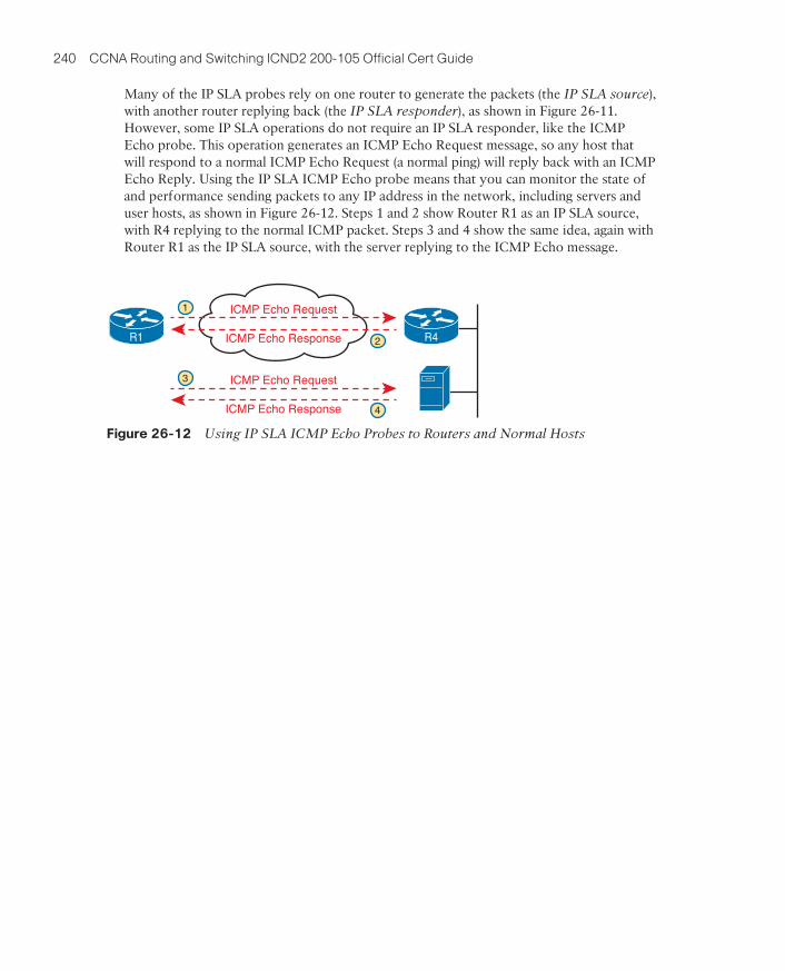
240 CCNA Routing and Switching ICND2 200-105 Official Cert Guide
Many of the IP SLA probes rely on one router to generate the packets (the IP SLA source), with another router replying back (the IP SLA responder), as shown in Figure 26-11. However, some IP SLA operations do not require an IP SLA responder, like the ICMP Echo probe. This operation generates an ICMP Echo Request message, so any host that will respond to a normal ICMP Echo Request (a normal ping) will reply back with an ICMP Echo Reply. Using the IP SLA ICMP Echo probe means that you can monitor the state of and performance sending packets to any IP address in the network, including servers and user hosts, as shown in Figure 26-12. Steps 1 and 2 show Router R1 as an IP SLA source, with R4 replying to the normal ICMP packet. Steps 3 and 4 show the same idea, again with Router R1 as the IP SLA source, with the server replying to the ICMP Echo message.
ICMP Echo Request
ICMP Echo Response
ICMP Echo Request
ICMP Echo Response
R1 R4
1
2
3
4
Figure 26-12 Using IP SLA ICMP Echo Probes to Routers and Normal Hosts

Key Topics 241
The show ip sla statistics 1 command provides some basic history through a counter of successes and failures, as shown in Example 26-14. In addition to the return code and RTT of the most recent operation, you get a counter of successes and failures of past operations. So, you can get a sense of whether the pings have been failing or not.
Example 26-14 Historical Success/Failure Counters with IP SLA
R1# show ip sla statistics 1
IPSLAs Latest Operation Statistics
IPSLA operation id: 1
Latest RTT: 16 milliseconds
Latest operation start time: 12:40:39 EST Tue Jan 5 2016
Latest operation return code: OK
Number of successes: 7
Number of failures: 0
Operation time to live: Forever

242 CCNA Routing and Switching ICND2 200-105 Official Cert Guide
With traditional IP SLA history, SLA takes the RTT and return code information and stores it in a history bucket. The show ip sla history command then displays one line per bucket. You can think of it as the same information in the show ip sla summary command seen back in Example 26-13, but going backward in time for the number of history buckets defined. Earlier Example 26-12 shows IP SLA operation 1 uses six buckets, so the output in Example 26-15 shows the results of the most recent six IP SLA operations for operation number 1.
Example 26-15 Displaying the Traditional Historical State of an IP SLA ICMP Echo Probe
R1# show ip sla history 1
Point by point History
Entry = Entry number
LifeI = Life index
BucketI = Bucket index
SampleI = Sample index
SampleT = Sample start time (milliseconds)
CompT = RTT (milliseconds)
Sense = Response return code
Entry LifeI BucketI SampleI SampleT CompT Sense TargetAddr
1 1 11 1 59438868 108 1 10.1.3.2
1 1 12 1 59498868 188 1 10.1.3.2
1 1 13 1 59558868 280 1 10.1.3.2
1 1 14 1 59618868 88 1 10.1.3.2
1 1 15 1 59678868 160 1 10.1.3.2
1 1 16 1 59738868 252 1 10.1.3.2

Key Topics 243
SPAN solves this problem by copying those frames from certain ports (SPAN source ports) to the port where the network analyzer sits (the SPAN destination port). Figure 26-16 shows the concept. In this case, the switch has two SPAN source ports, G1/0/11 and G1/0/12. Frames received on both ports are copied out to the SPAN destination port G1/0/21.
Layer 2 Switch
Unicast Frames
NetworkAnalyzer
G 1/0/11
G 1/0/21
G 1/0/12
Unicast Frames
SPAN SPAN
Figure 26-16 SPAN Copies (Mirrors) Frames to the Network Analyzer

244 CCNA Routing and Switching ICND2 200-105 Official Cert Guide
First, consider the SPAN example in Figure 26-17. It shows the concept of using port G1/0/11 as a source port. However, the logic goes beyond identifying the source port; it also specifies for the switch to copy frames being transmitted (Tx) out that switch port. The SPAN logic would watch for frames sent out that switch port, and then copy the frames out the SPAN destination port (G1/0/21 in this case).
SPAN Source PortG 1/0/12
Tx
G 1/0/11
SPAN Transmit G 1/0/11
Copied...
NetworkAnalyzer
G 1/0/21
Figure 26-17 SPAN Construct: Source Port G1/0/11, for Frames in the Transmit Direction

Key Topics 245
SPAN configuration actually has quite a few dependencies, with the following list mention-ing some of the most important dependencies:
■ A SPAN destination port can be used with only one SPAN session at a time.
■ A SPAN destination port cannot also be a SPAN source port.
■ When configured as a SPAN destination port, the switch no longer treats the port as a normal port. That is, the switch does not learn MAC addresses for received frames, or send frames based on matching the MAC table, for that port.
■ A SPAN destination port can be unconfigured from one monitor session (no monitor
session number destination interface type number) and then added to another monitor session.
■ Multiple SPAN sources can be used in a single SPAN session.
■ One SPAN session cannot mix interfaces and VLAN sources; that is, the sources must all be interfaces or all be VLANs.
■ One SPAN session can use any combination of directions (transmit, receive, and both) as applied to different SPAN sources.
■ EtherChannel interfaces can be used as source ports. Frames for all ports in the EtherChannel will be considered by SPAN.
■ Trunks can be used as source ports. When used, by default, SPAN includes frames from all VLANs on that trunk, but SPAN VLAN filtering can limit the VLANs included.

246 CCNA Routing and Switching ICND2 200-105 Official Cert Guide
Chapter 27A VM—that is, an OS instance that is decoupled from the server hardware—still must execute on hardware. Each VM has configuration as to the minimum number of vCPUs it needs, minimum RAM, and so on. The virtualization system then starts each VM on some physical server so that enough physical server hardware capacity exists to support all the VMs running on that host. So, at any one point in time, each VM is running on a physi-cal server, using a subset of the CPU, RAM, storage, and NICs on that server. Figure 27-3 shows a graphic of that concept, with four separate VMs running on one physical server.
App
OS OS OS OS
Storage CPU RAM Network
Hypervisor
App App
Virtual Machine Virtual Machine Virtual Machine Virtual Machine
App App App App App App App App App
Figure 27-3 Four VMs Running on One Host; Hypervisor Manages the Hardware

Key Topics 247
To get a broader sense of what it means for a service to be a cloud service, examine this list of five criteria for a cloud computing service. The list is derived from the definition of cloud computing as put forth by the U.S. National Institute of Standards and Technology (NIST):
On-demand self-service: The IT consumer chooses when to start and stop using the ser-vice, without any direct interaction with the provider of the service.
Broad network access: The service must be available from many types of devices and over many types of networks (including the Internet).
Resource pooling: The provider creates a pool of resources (rather than dedicating spe-cific servers for use only by certain consumers), and dynamically allocates resources from that pool for each new request from a consumer.
Rapid elasticity: To the consumer, the resource pool appears to be unlimited (that is, it expands quickly, so it is called elastic), and the requests for new service are filled quickly.
Measured service: The provider can measure the usage and report that usage to the con-sumer, both for transparency and for billing.

248 CCNA Routing and Switching ICND2 200-105 Official Cert Guide
IaaS offers a similar idea, but the consumer receives the use of a VM. You specify the amount of hardware performance/capacity to allocate to the VM (number of virtual CPUs, amount of RAM, and so on) as shown in Figure 27-9. You can even pick an OS to use. Once selected, the cloud provider starts the VM, which boots the chosen OS.
NOTE In the virtualization and cloud world, starting a VM is often called spinning up a VM or instantiating a VM.
Storage CPU RAM Network
Operating System (Optional) User Picks
User Picks
Customer Installs Apps Later
1
2
1
Figure 27-9 IaaS Concept

Key Topics 249
With Software as a Service (SaaS), the consumer receives a service with working software. The cloud provider may use VMs, possibly many VMs, to create the service, but those are hidden from the consumer. The cloud provider licenses, installs, and supports whatever software is required. The cloud provider then monitors performance of the application. However, the consumer chooses to use the application, signs up for the service, and starts using the application—no further installation work required. Figure 27-11 shows these main concepts.
Application User Picks
OS,HardwareHidden
1
Storage CPU RAM Network
Operating System (Optional) 2
Figure 27-11 SaaS Concept

250 CCNA Routing and Switching ICND2 200-105 Official Cert Guide
The primary reasons to choose one PaaS service over another, or to choose a PaaS solu-tion instead of IaaS, is the mix of development tools. Without experience as a developer, it can be difficult to tell whether one PaaS service might be better. You can still make some choices about sizing the PaaS VMs, similar to IaaS tools when setting up some PaaS services, as shown in Figure 27-12, but the developer tools included are the key to a PaaS service.
Storage CPU RAM Network
Operating System
Development Environment and Tools (Platform)PrimaryFactor
Figure 27-12 PaaS Concept

Key Topics 251
Using the Internet as the WAN connectivity to a public cloud is both a blessing and a curse in some ways. Using the Internet can help you get started with public cloud, and to get working quickly, but it also means that you do not have to do any planning before deploy-ing a public cloud service. With a little planning, a network engineer can see some of the negatives of using the Internet—the same negatives when using the Internet for other pur-poses—which then might make you want to use alternative WAN connections. Those nega-tives for using the Internet for public cloud access are
Security: The Internet is less secure than private WAN connections in that a “man in the middle” can attempt to read the contents of data that passes to/from the public cloud.
Capacity: Moving an internal application to the public cloud increases network traffic, so the question of whether the enterprise’s Internet links can handle the additional load needs to be considered.
Quality of Service (QoS): The Internet does not provide QoS, whereas private WANs can. Using the Internet may result in a worse user experience than desired, because of higher delay (latency), jitter, and packet loss.
No WAN SLA: ISPs typically will not provide a service level agreement (SLA) for WAN performance and availability to all destinations of a network. WAN service providers are much more likely to offer performance and availability SLAs.

252 CCNA Routing and Switching ICND2 200-105 Official Cert Guide
Table 27-2 summarizes some of these key pros and cons for the public WAN options for cloud computing, for study and reference.
Table 27-2 Comparison of Key Pros and Cons
Internet Internet VPN
MPLS VPN
Ethernet WAN
Intercloud Exchange
Secure No Yes Yes Yes Yes
QoS No No Yes Yes Yes
Requires capacity planning Yes Yes Yes Yes Yes
Easier migration to new provider Yes Yes No No Yes
Can begin using public cloud quickly
Yes Yes No No No

Key Topics 253
Given those steps, the enterprise can choose to do something simple: just update its own DNS to refer to the public IP address used by its application as running at the public cloud provider. Figure 27-22 shows the user flow after making changes to the enterprise DNS.
Enterprise
WAN
198.51.100.1
App1 (Link: app1.example.com)App2 (Link: app2.example.com)
Cloud Provider
198.51.100.1
App2.example.com
DNS DNS
2
1
3 4
A-Record:app2.example.com
is 198.51.100.1
Figure 27-22 Enterprise DNS Is Updated with Addresses of Public Cloud Apps

254 CCNA Routing and Switching ICND2 200-105 Official Cert Guide
Chapter 28Now broaden your thinking for a moment, and try to think of everything a router or switch might do when receiving, processing, and forwarding a message. Of course, the forwarding decision is part of the logic; in fact, the data plane is often called the forwarding plane. But think beyond matching the destination address to a table. For perspective, the following list details some of the more common actions that a networking device does that fit into the data plane:
■ De-encapsulating and re-encapsulating a packet in a data link frame (routers, Layer 3 switches)
■ Adding or removing an 802.1Q trunking header (routers and switches)
■ Matching the destination MAC address to the MAC address table (Layer 2 switches)
■ Matching the destination IP address to the IP routing table (routers, Layer 3 switches)
■ Encrypting the data and adding a new IP header (for VPN processing)
■ Changing the source or destination IP address (for NAT processing)
■ Discarding a message due to a filter (ACLs, port security)

Key Topics 255
The following list includes many of the more common control plane protocols:
■ Routing protocols (OSPF, EIGRP, RIP, BGP)
■ IPv4 ARP
■ IPv6 NDP
■ Switch MAC learning
■ STP

256 CCNA Routing and Switching ICND2 200-105 Official Cert Guide
Note that a switch still has a general-purpose CPU and RAM as well, as shown in Figure 28-4. IOS runs in the CPU and uses RAM. Most of the control and management plane func-tions run in IOS. The data plane function (and the control plane function of MAC learning) happens in the ASIC.
CPU(IOS)
Switch Data Plane
RAM(Various)
ASICLogic
TCAMTable Lookup
Figure 28-4 Key Internal Processing Points in a Typical Switch

Key Topics 257
To better understand the idea of a controller, consider the case shown in Figure 28-5, in which one SDN controller centralizes all important control plane functions. First, the con-troller sits anywhere in the network that has IP reachability to the devices in the network. Each of the network devices still has a data plane. However, note that none of the devices has a control plane. In the variation of SDN as shown in Figure 28-5, the controller (or a program making use of the controller) directly programs the data plane entries into each device’s tables. The networking devices do not populate their forwarding tables with tradi-tional distributed control plane processes.
Data Plane
ControllerSouthboundInterface (SBI)
Network Device Network DeviceNetwork Device
packetpacket
ControlPlane
Data Plane Data Plane
ControlPlane
ControlPlane
packet packet
Figure 28-5 Centralized Control Plane and a Distributed Data Plane

258 CCNA Routing and Switching ICND2 200-105 Official Cert Guide
A controller does much of the work needed for the control plane in a centralized control model. It gathers all sorts of useful information about the network, like the items in the pre-vious list. The controller itself can create a centralized repository of all this useful informa-tion about the network.
A controller’s Northbound Interface (NBI) opens the controller so its data and functions can be used by other programs, enabling network programmability, with much quicker develop-ment. Programs can pull information from the controller, using the controller’s APIs. The NBIs also enable programs to use the controller’s abilities to program flows into the devices using the controller’s SBIs.

Key Topics 259
Figure 28-7 shows the big ideas with a REST API. The application runs on a host at the top of the figure. In this case, at Step 1, it sends an HTTP GET request to a particular URI. The HTTP GET is like any other HTTP GET, even like those used to retrieve web pages. However, the URI is not for a web page, but rather identifies an object on the controller, typically a data structure that the application needs to learn and then process. For example, the URI might identify an object that is the list of physical interfaces on a specific device along with the status of each.
Controller API
APPVariables
HTTP GET Response: JSON data
HTTP GET URI
1 2
3
Figure 28-7 Process Example of a GET Using a REST API

260 CCNA Routing and Switching ICND2 200-105 Official Cert Guide
To make it all work, ACI uses a centralized controller called the Application Policy Infrastructure Controller (APIC), as shown in Figure 28-9. The name defines the function in this case: It is the controller that creates application policies for the data center infra-structure. The APIC, of course, has a convenient GUI, but the power comes in software control—that is, network programmability. The same virtualization software, or cloud or automation software, even scripts written by the network engineer, can define the endpoint groups, policies, and so on to the APIC. But all these players access the ACI system by interfacing to the APIC; the network engineer no longer needs to connect to each individual switch and configure CLI commands.
VirtualizationSoftware
CloudSoftware
AutomationSoftware
APICController
ACI DC with Nexus 9000 Switches
GUI orScripts
OpFlex
Some Control Planein Switches
Figure 28-9 Controlling the ACI Data Center Network Using the APIC

Key Topics 261
Figure 28-10 shows a general view of the APIC-EM controller architecture, with a few of the APIC-EM apps, the REST API, and a list of the SBIs.
TopologyVisualization
REST API iWANPlug nPlay
PathTrace
Core Features
CLI (Telnet, SSH), SNMP
Your App
Any TopologyMany Device Models
Core
NBI
SBI
Controller
Apps from Cisco
Figure 28-10 APIC-EM Controller Model

262 CCNA Routing and Switching ICND2 200-105 Official Cert Guide
The three example SDN branches in this section of the book were chosen to provide a wide variety for the sake of learning. For instance, with Cisco OSC (using OpenFlow) and with Cisco ACI, the network engineer now works with the controller rather than individual devices. However, they differ to some degree in how much of the control plane work is centralized. Table 28-2 lists those and other comparison points taken from this section, for easy review and study.
Table 28-2 Points of Comparison: Open SDN, ACI, and APIC Enterprise
Criteria Open SDN ACI APIC Enterprise
Changes how the device control plane works versus traditional networking
Yes Yes No
Creates centralized point from which humans and automation control the network
Yes Yes Yes
Degree to which the architecture centralizes the control plane
Mostly Partially N/A1
SBIs used OpenFlow OpFlex CLI, SNMP
Controllers mentioned in this chapter OpenDaylight, Cisco OSC
APIC APIC-EM
Organization that is the primary definer/owner ONF Cisco Cisco
1 The control plan remains the same in the networking devices, so in that sense, the control plane is not centralized at all.