Chapter III: Softcopy Photogrammetry and Desktop Mappingcomputer-based, softcopy photogrammetric...
12
1 Using Scanned Aerial Photographs 1 by Roy Welch and Thomas Jordan Center for Remote Sensing and Mapping Science (CRMS) University of Georgia - Athens, GA 30602 Introduction Aerial photographs are a major data source in the construction of geographic information system (GIS) databases. With the introduction of computer-based, softcopy photogrammetric mapping and GIS systems that operate in a desktop computing environment and are able to manipulate both vector and raster data, the demand for images in raster (digital) format has increased sharply (Welch, 1989, 1992; ASPRS, 1996). While the intent of this chapter is to provide guidelines related to the use of aerial photographs in digital format, it must be stressed that aerial photographs in hardcopy format may prove to be a more economical solution for many mapping and GIS database construction tasks. Conversion of aerial photographs to raster format Aerial photographs recorded with standard mapping cameras must be scanned and converted to raster format before they can be used in digital image processing/mapping environments. Decisions made concerning the scanning process will determine, in large part, the geometric accuracy of the scanned photographs, the amount of information that can be extracted and the speed with which the images can be processed. The basic function of a scanner is to convert a hardcopy photograph to digital format (that is, softcopy format). Scanners are designed to capture image data in reflection (paper print) and/or transmission (film transparency) modes. Because film transparencies tend to have higher spatial resolutions and a greater range of gray values than paper prints, they are the preferred source material when converting aerial photographs to digital images. Low-cost, flatbed scanners (<$5,000) are generally designed for desktop publishing applications. They offer adequate spatial and radiometric resolution for capturing detail from large scale aerial photographs, but may introduce unwanted geometric distortions into the scanned image. Some low-cost, flatbed scanners advertise high resolution, but are actually scanning at low resolution and resampling to higher resolutions through the use of software. These types of scanners are useful for documents and graphics applications, but are not optimal for scanning aerial photographs to be used in GIS or mapping 1 Reprinted from Welch, R. and T.R. Jordan, 1996. Using Scanned Air Photographs. In Raster Imagery in Geographic Information Systems, (S. Morain and S.L. Baros, eds), Onward Press, pp. 55-69.
Transcript of Chapter III: Softcopy Photogrammetry and Desktop Mappingcomputer-based, softcopy photogrammetric...
1
Using Scanned Aerial Photographs1 by
Roy Welch and Thomas Jordan Center for Remote Sensing and Mapping Science (CRMS)
University of Georgia - Athens, GA 30602
Introduction Aerial photographs are a major data source in the construction of
geographic information system (GIS) databases. With the introduction of computer-based, softcopy photogrammetric mapping and GIS systems that operate in a desktop computing environment and are able to manipulate both vector and raster data, the demand for images in raster (digital) format has increased sharply (Welch, 1989, 1992; ASPRS, 1996). While the intent of this chapter is to provide guidelines related to the use of aerial photographs in digital format, it must be stressed that aerial photographs in hardcopy format may prove to be a more economical solution for many mapping and GIS database construction tasks.
Conversion of aerial photographs to raster format Aerial photographs recorded with standard mapping cameras must be
scanned and converted to raster format before they can be used in digital image processing/mapping environments. Decisions made concerning the scanning process will determine, in large part, the geometric accuracy of the scanned photographs, the amount of information that can be extracted and the speed with which the images can be processed.
The basic function of a scanner is to convert a hardcopy photograph to digital format (that is, softcopy format). Scanners are designed to capture image data in reflection (paper print) and/or transmission (film transparency) modes. Because film transparencies tend to have higher spatial resolutions and a greater range of gray values than paper prints, they are the preferred source material when converting aerial photographs to digital images.
Low-cost, flatbed scanners (<$5,000) are generally designed for desktop publishing applications. They offer adequate spatial and radiometric resolution for capturing detail from large scale aerial photographs, but may introduce unwanted geometric distortions into the scanned image. Some low-cost, flatbed scanners advertise high resolution, but are actually scanning at low resolution and resampling to higher resolutions through the use of software. These types of scanners are useful for documents and graphics applications, but are not optimal for scanning aerial photographs to be used in GIS or mapping
1 Reprinted from Welch, R. and T.R. Jordan, 1996. Using Scanned Air Photographs. In Raster Imagery in Geographic Information Systems, (S. Morain and S.L. Baros, eds), Onward Press, pp. 55-69.
2
applications where both high spatial resolution and good geometric accuracy are essential. Top quality scanners designed specifically for digital photogrammetry include those manufactured by Carl Zeiss, Inc., Helava Associates, Inc., Vexcel Imaging Corporation, and Wehrli and Associates, Inc. These scanners can meet all requirements for resolution and accuracy, but costs generally exceed $40,000. Consequently, it may be appropriate to make use of available commercial scanning services offered by companies such as ImageScans (Denver, Colorado) and Precision Photo Laboratories (Dayton, Ohio). Photographs are scanned for a nominal fee and the data returned on CD-ROM or tape. In the following paragraphs, some of the considerations associated with scanning aerial photographs, rectifying the digital image files and using orthophoto products are discussed.
Photo scale, scanning resolution, information content and data volume
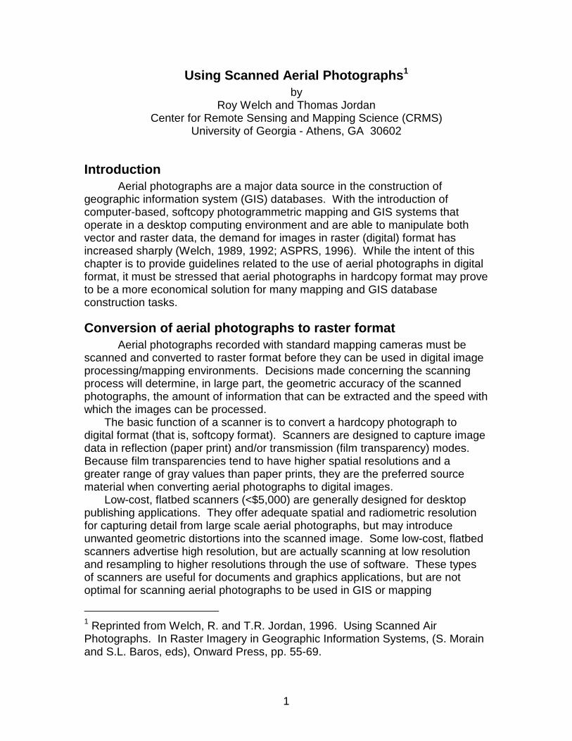
Aerial photographs are recorded with photogrammetric mapping cameras from altitudes of approximately 300 m to over 20,000 m. If a standard lens focal length of 15 cm is assumed, photo scales will range from about 1:2,000 (very large scale) to approximately 1:135,000 (very small scale) (Figure 1; Welch, 1993).
0
20000
40000
60000
80000
100000
120000
140000
0
2000
4000
6000
8000
1000
0
1200
0
1400
0
1600
0
1800
0
2000
0
Flying Height (m)
Ph
oto
Sca
le F
acto
r
Figure 1. Photo scale factor plotted as a function of flying height for a typical photogrammetric camera equipped with a lens cone having a focal length of 15 cm.
3
PixelsDN (0-255)
23 cm
23 cm
Scan lines
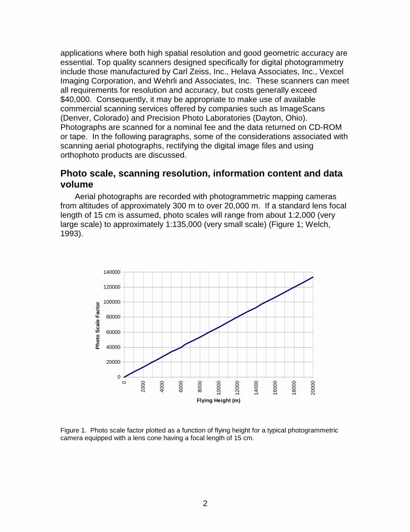
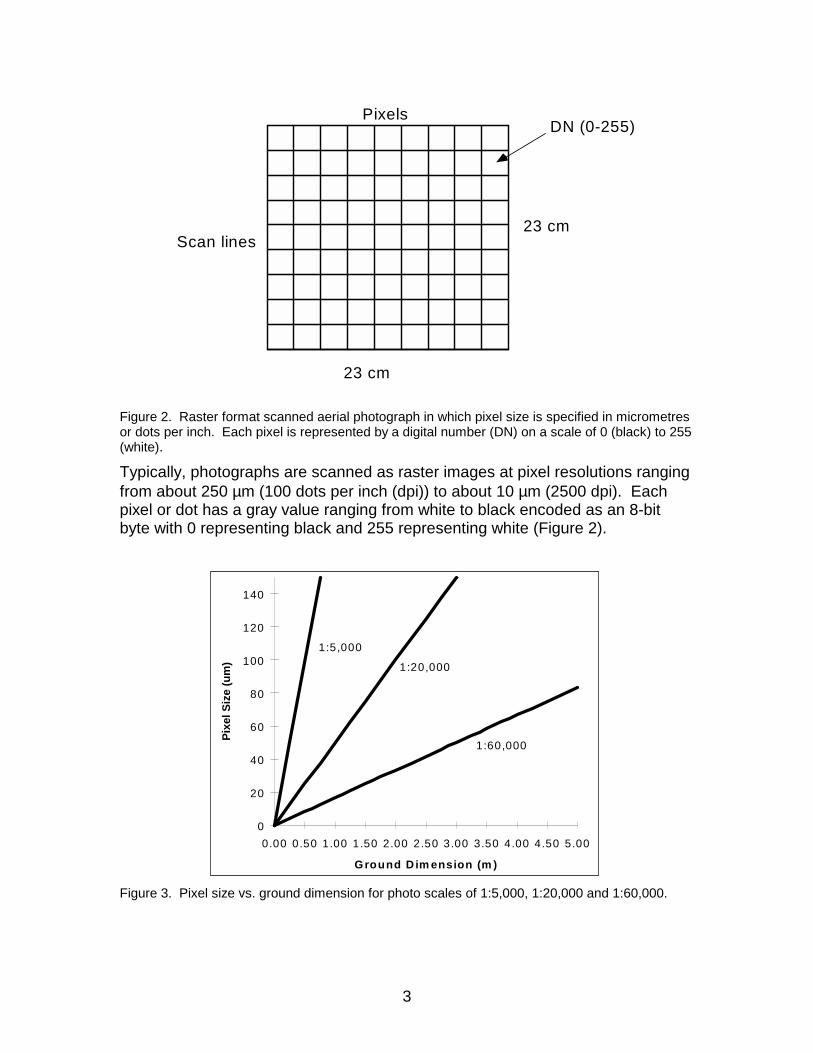
Figure 2. Raster format scanned aerial photograph in which pixel size is specified in micrometres or dots per inch. Each pixel is represented by a digital number (DN) on a scale of 0 (black) to 255 (white).
Typically, photographs are scanned as raster images at pixel resolutions ranging from about 250 µm (100 dots per inch (dpi)) to about 10 µm (2500 dpi). Each pixel or dot has a gray value ranging from white to black encoded as an 8-bit byte with 0 representing black and 255 representing white (Figure 2).
0
20
40
60
80
100
120
140
0.00 0.50 1.00 1.50 2.00 2.50 3.00 3.50 4.00 4.50 5.00
Ground D im ension (m )
Pix
el S
ize
(um
)
1:5,000
1:20,000
1:60,000
Figure 3. Pixel size vs. ground dimension for photo scales of 1:5,000, 1:20,000 and 1:60,000.
4
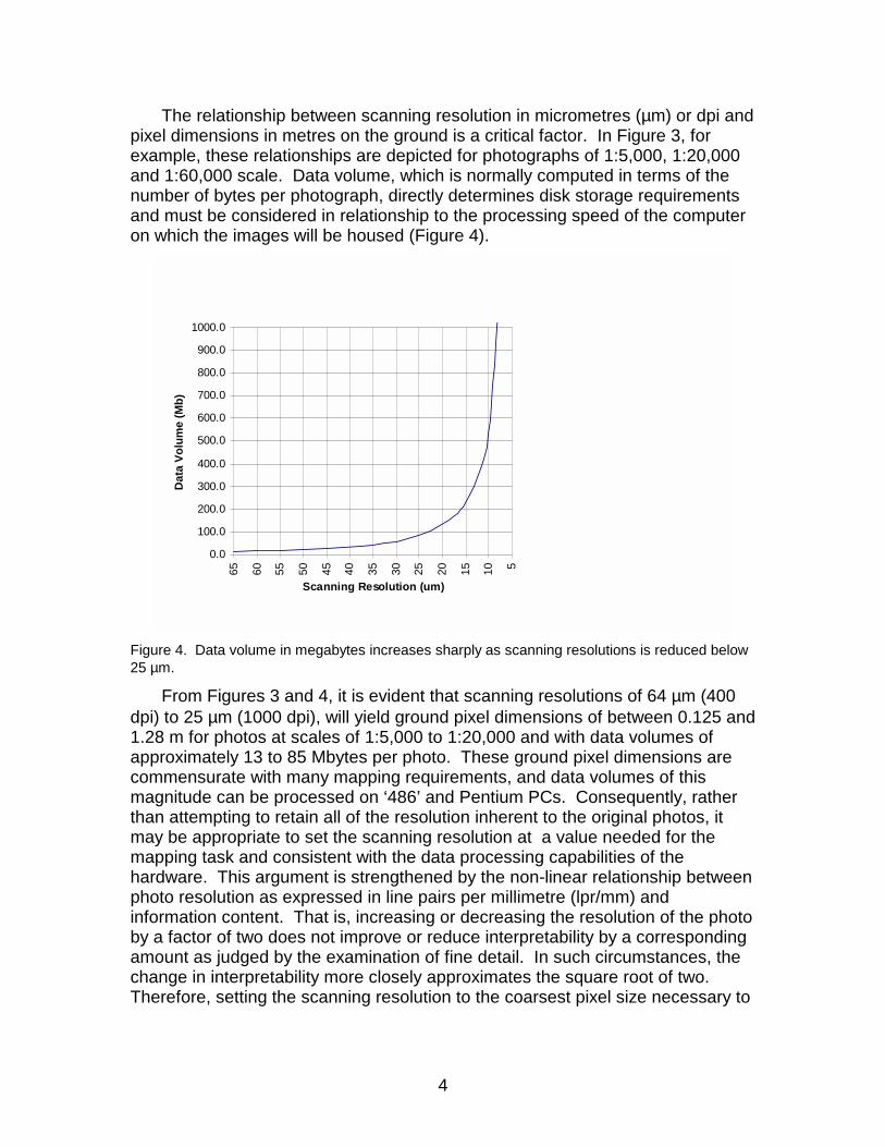
The relationship between scanning resolution in micrometres (µm) or dpi and pixel dimensions in metres on the ground is a critical factor. In Figure 3, for example, these relationships are depicted for photographs of 1:5,000, 1:20,000 and 1:60,000 scale. Data volume, which is normally computed in terms of the number of bytes per photograph, directly determines disk storage requirements and must be considered in relationship to the processing speed of the computer on which the images will be housed (Figure 4).
0.0
100.0
200.0
300.0
400.0
500.0
600.0
700.0
800.0
900.0
1000.0
65 60 55 50 45 40 35 30 25 20 15 10 5
Scanning Resolution (um)
Dat
a V
olu
me
(Mb
)
Figure 4. Data volume in megabytes increases sharply as scanning resolutions is reduced below 25 µm.
From Figures 3 and 4, it is evident that scanning resolutions of 64 µm (400 dpi) to 25 µm (1000 dpi), will yield ground pixel dimensions of between 0.125 and 1.28 m for photos at scales of 1:5,000 to 1:20,000 and with data volumes of approximately 13 to 85 Mbytes per photo. These ground pixel dimensions are commensurate with many mapping requirements, and data volumes of this magnitude can be processed on ‘486’ and Pentium PCs. Consequently, rather than attempting to retain all of the resolution inherent to the original photos, it may be appropriate to set the scanning resolution at a value needed for the mapping task and consistent with the data processing capabilities of the hardware. This argument is strengthened by the non-linear relationship between photo resolution as expressed in line pairs per millimetre (lpr/mm) and information content. That is, increasing or decreasing the resolution of the photo by a factor of two does not improve or reduce interpretability by a corresponding amount as judged by the examination of fine detail. In such circumstances, the change in interpretability more closely approximates the square root of two. Therefore, setting the scanning resolution to the coarsest pixel size necessary to
5
identify the smallest features to be extracted and mapped is an appropriate strategy that need not seriously degrade information content.
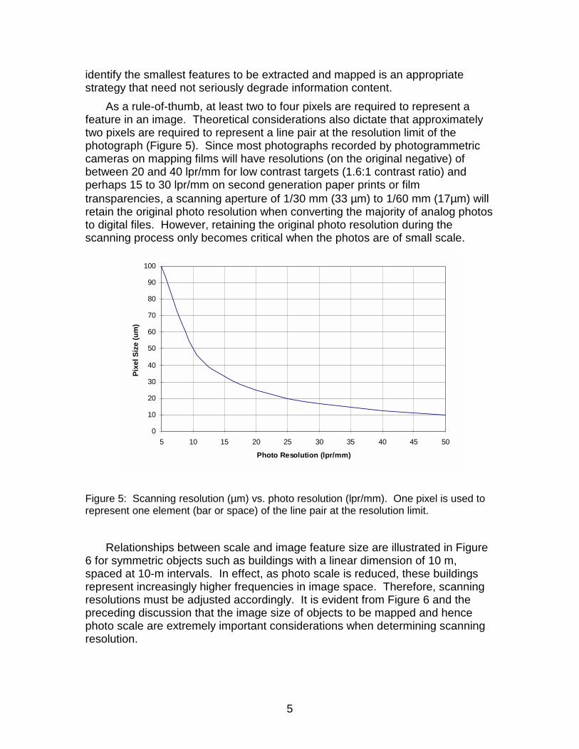
As a rule-of-thumb, at least two to four pixels are required to represent a feature in an image. Theoretical considerations also dictate that approximately two pixels are required to represent a line pair at the resolution limit of the photograph (Figure 5). Since most photographs recorded by photogrammetric cameras on mapping films will have resolutions (on the original negative) of between 20 and 40 lpr/mm for low contrast targets (1.6:1 contrast ratio) and perhaps 15 to 30 lpr/mm on second generation paper prints or film transparencies, a scanning aperture of 1/30 mm (33 µm) to 1/60 mm (17µm) will retain the original photo resolution when converting the majority of analog photos to digital files. However, retaining the original photo resolution during the scanning process only becomes critical when the photos are of small scale.
0
10
20
30
40
50
60
70
80
90
100
5 10 15 20 25 30 35 40 45 50
Photo Resolution (lpr/mm)
Pix
el S
ize
(um
)
Figure 5: Scanning resolution (µm) vs. photo resolution (lpr/mm). One pixel is used to represent one element (bar or space) of the line pair at the resolution limit.
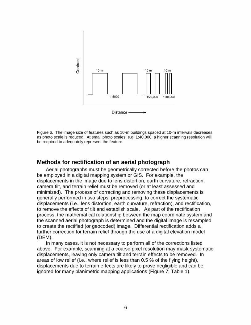
Relationships between scale and image feature size are illustrated in Figure 6 for symmetric objects such as buildings with a linear dimension of 10 m, spaced at 10-m intervals. In effect, as photo scale is reduced, these buildings represent increasingly higher frequencies in image space. Therefore, scanning resolutions must be adjusted accordingly. It is evident from Figure 6 and the preceding discussion that the image size of objects to be mapped and hence photo scale are extremely important considerations when determining scanning resolution.
6
Figure 6. The image size of features such as 10-m buildings spaced at 10-m intervals decreases as photo scale is reduced. At small photo scales, e.g. 1:40,000, a higher scanning resolution will be required to adequately represent the feature.
Methods for rectification of an aerial photograph Aerial photographs must be geometrically corrected before the photos can
be employed in a digital mapping system or GIS. For example, the displacements in the image due to lens distortion, earth curvature, refraction, camera tilt, and terrain relief must be removed (or at least assessed and minimized). The process of correcting and removing these displacements is generally performed in two steps: preprocessing, to correct the systematic displacements (i.e., lens distortion, earth curvature, refraction), and rectification, to remove the effects of tilt and establish scale. As part of the rectification process, the mathematical relationship between the map coordinate system and the scanned aerial photograph is determined and the digital image is resampled to create the rectified (or geocoded) image. Differential rectification adds a further correction for terrain relief through the use of a digital elevation model (DEM).
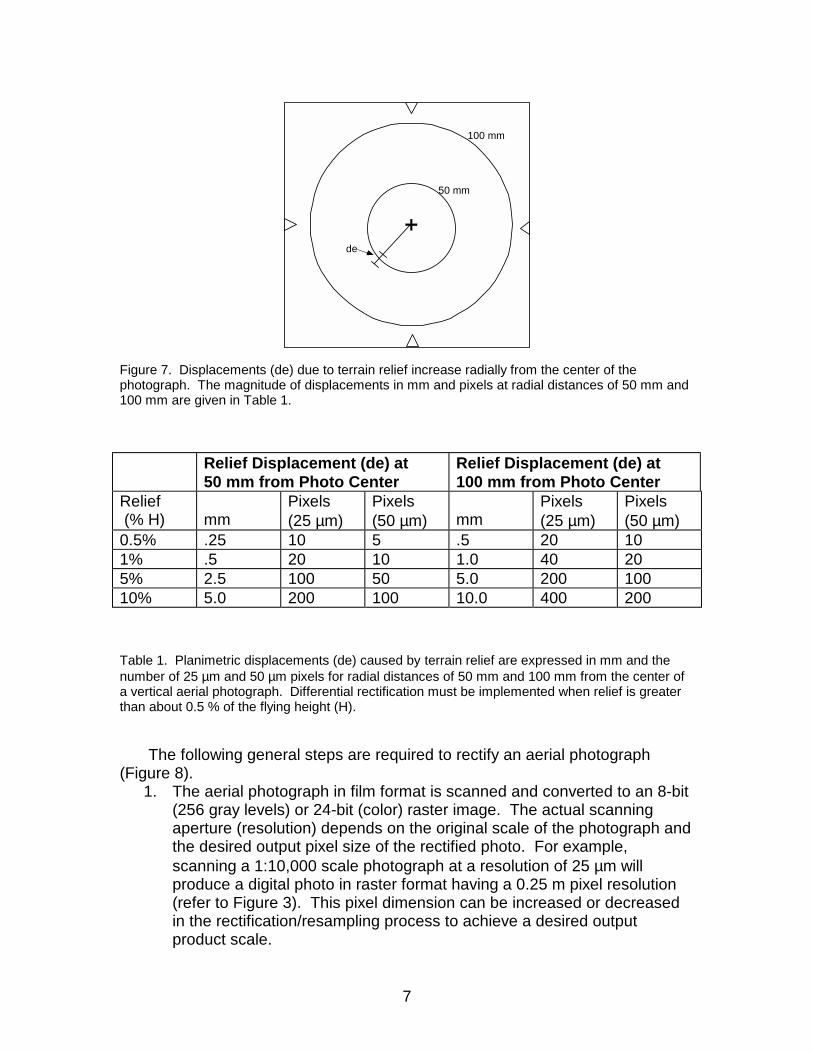
In many cases, it is not necessary to perform all of the corrections listed above. For example, scanning at a coarse pixel resolution may mask systematic displacements, leaving only camera tilt and terrain effects to be removed. In areas of low relief (i.e., where relief is less than 0.5 % of the flying height), displacements due to terrain effects are likely to prove negligible and can be ignored for many planimetric mapping applications (Figure 7; Table 1).
7
100 mm
50 mm
de
Figure 7. Displacements (de) due to terrain relief increase radially from the center of the photograph. The magnitude of displacements in mm and pixels at radial distances of 50 mm and 100 mm are given in Table 1.
Relief Displacement (de) at 50 mm from Photo Center
Relief Displacement (de) at 100 mm from Photo Center
Relief (% H)
mm
Pixels (25 µm)
Pixels (50 µm)
mm
Pixels (25 µm)
Pixels (50 µm)
0.5% .25 10 5 .5 20 10 1% .5 20 10 1.0 40 20 5% 2.5 100 50 5.0 200 100 10% 5.0 200 100 10.0 400 200
Table 1. Planimetric displacements (de) caused by terrain relief are expressed in mm and the number of 25 µm and 50 µm pixels for radial distances of 50 mm and 100 mm from the center of a vertical aerial photograph. Differential rectification must be implemented when relief is greater than about 0.5 % of the flying height (H).
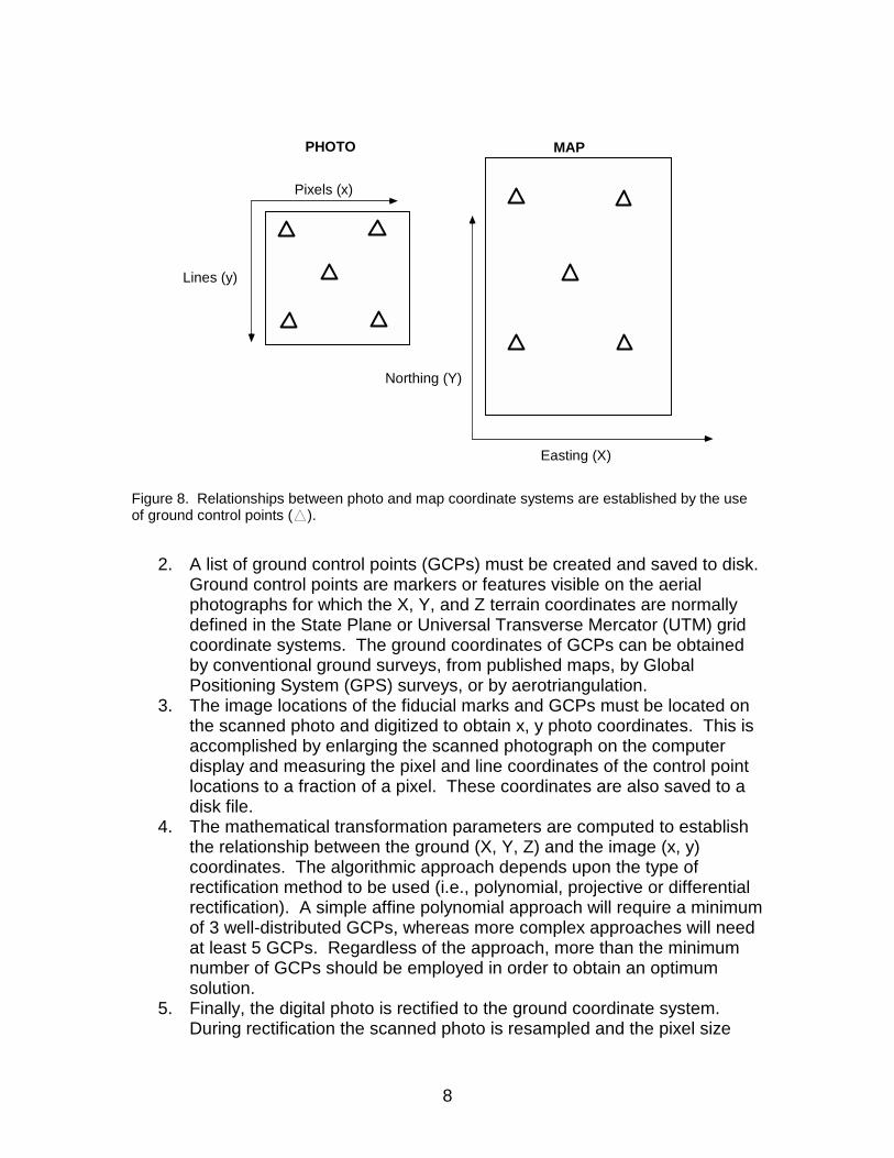
The following general steps are required to rectify an aerial photograph (Figure 8).
1. The aerial photograph in film format is scanned and converted to an 8-bit (256 gray levels) or 24-bit (color) raster image. The actual scanning aperture (resolution) depends on the original scale of the photograph and the desired output pixel size of the rectified photo. For example, scanning a 1:10,000 scale photograph at a resolution of 25 µm will produce a digital photo in raster format having a 0.25 m pixel resolution (refer to Figure 3). This pixel dimension can be increased or decreased in the rectification/resampling process to achieve a desired output product scale.
8
PHOTO MAP
Pixels (x)
Easting (X)
Lines (y)
Northing (Y)
Figure 8. Relationships between photo and map coordinate systems are established by the use of ground control points (h).
2. A list of ground control points (GCPs) must be created and saved to disk. Ground control points are markers or features visible on the aerial photographs for which the X, Y, and Z terrain coordinates are normally defined in the State Plane or Universal Transverse Mercator (UTM) grid coordinate systems. The ground coordinates of GCPs can be obtained by conventional ground surveys, from published maps, by Global Positioning System (GPS) surveys, or by aerotriangulation.
3. The image locations of the fiducial marks and GCPs must be located on the scanned photo and digitized to obtain x, y photo coordinates. This is accomplished by enlarging the scanned photograph on the computer display and measuring the pixel and line coordinates of the control point locations to a fraction of a pixel. These coordinates are also saved to a disk file.
4. The mathematical transformation parameters are computed to establish the relationship between the ground (X, Y, Z) and the image (x, y) coordinates. The algorithmic approach depends upon the type of rectification method to be used (i.e., polynomial, projective or differential rectification). A simple affine polynomial approach will require a minimum of 3 well-distributed GCPs, whereas more complex approaches will need at least 5 GCPs. Regardless of the approach, more than the minimum number of GCPs should be employed in order to obtain an optimum solution.
5. Finally, the digital photo is rectified to the ground coordinate system. During rectification the scanned photo is resampled and the pixel size
9
modified as required to correspond with other raster data sets that may be part of the database.
6. Differential rectification requires an additional step and employs terrain height data from a DEM to correct for relief displacements in the image.
Orthophotographs Orthophotographs are scaled aerial photographs from which
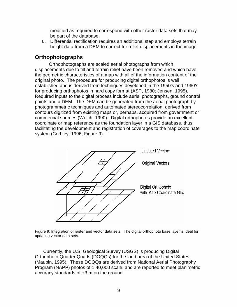
displacements due to tilt and terrain relief have been removed and which have the geometric characteristics of a map with all of the information content of the original photo. The procedure for producing digital orthophotos is well established and is derived from techniques developed in the 1950’s and 1960’s for producing orthophotos in hard copy format (ASP, 1980; Jensen, 1995). Required inputs to the digital process include aerial photographs, ground control points and a DEM. The DEM can be generated from the aerial photograph by photogrammetric techniques and automated stereocorrelation, derived from contours digitized from existing maps or, perhaps, acquired from government or commercial sources (Welch, 1990). Digital orthophotos provide an excellent coordinate or map reference as the foundation layer in a GIS database, thus facilitating the development and registration of coverages to the map coordinate system (Corbley, 1996; Figure 9).
Figure 9: Integration of raster and vector data sets. The digital orthophoto base layer is ideal for updating vector data sets.
Currently, the U.S. Geological Survey (USGS) is producing Digital Orthophoto Quarter Quads (DOQQs) for the land area of the United States (Maupin, 1995). These DOQQs are derived from National Aerial Photography Program (NAPP) photos of 1:40,000 scale, and are reported to meet planimetric accuracy standards of +3 m on the ground.
10
The DOQQs and similar digital orthophoto products are ideal for GIS database construction/update using software packages such as ARC/INFO ® (ESRI, Inc.), Desktop Mapping System (DMS)™ (R-WEL, Inc.), EASI/PACE™ (PCI, Inc.), Imagine® (ERDAS, Inc.), and MGE™ (Intergraph). However, it is important to carefully consider software capabilities when contemplating the use of aerial photographs for data base construction and/or revision.
Map database compilation and revision from digital data sets will necessitate overlay of existing vector files, enlargement or reduction of images, an ability to create vector files with attached attributes from raster image data and a method for editing the vector files in digital format (Usery and Welch, 1989). Some software packages such as ArcView® (ESRI, Inc), AutoCAD® (Autodesk, Inc.), MapInfo® (MapInfo Corp.) and O’Map™ (R-WEL, Inc.) require the use of rectified photos or orthophotos as the backdrop upon which to superimpose vector files already in a UTM or State Plane coordinate system. Others, such as DMS, Imagine and EASI/PACE, will allow rectification of uncorrected raster photo files and also permit the user to generate vector files in registration with these data sets.
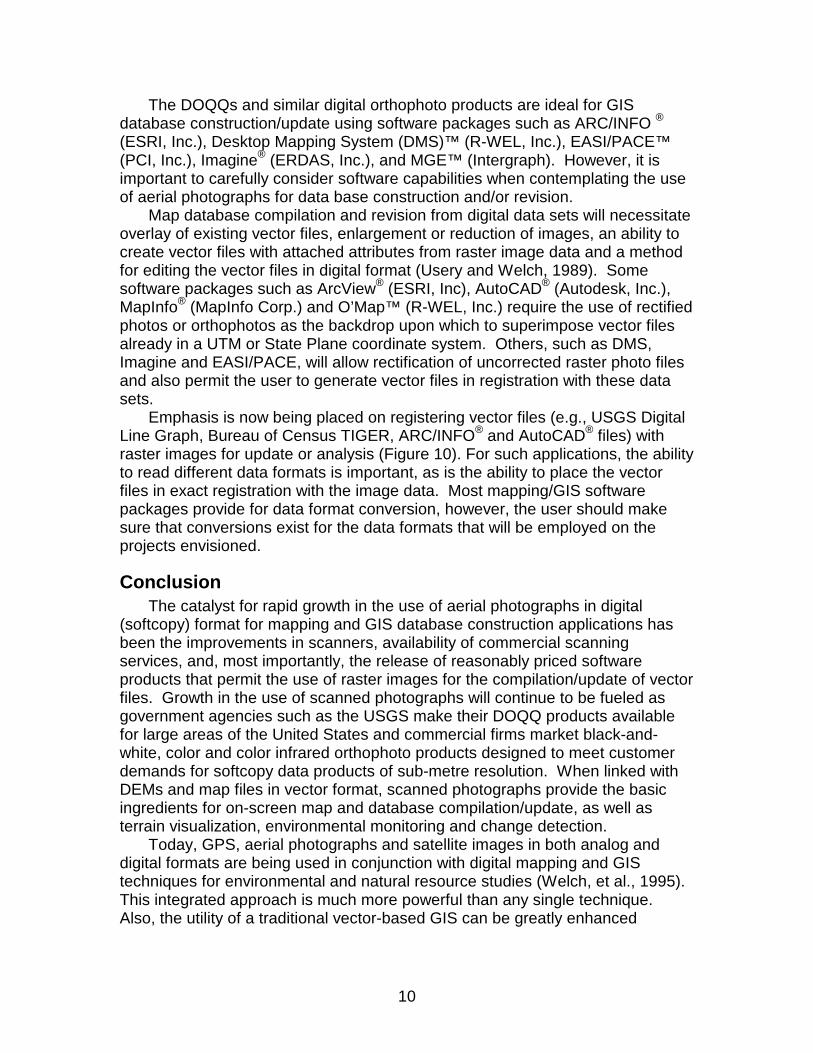
Emphasis is now being placed on registering vector files (e.g., USGS Digital Line Graph, Bureau of Census TIGER, ARC/INFO® and AutoCAD® files) with raster images for update or analysis (Figure 10). For such applications, the ability to read different data formats is important, as is the ability to place the vector files in exact registration with the image data. Most mapping/GIS software packages provide for data format conversion, however, the user should make sure that conversions exist for the data formats that will be employed on the projects envisioned.
Conclusion The catalyst for rapid growth in the use of aerial photographs in digital
(softcopy) format for mapping and GIS database construction applications has been the improvements in scanners, availability of commercial scanning services, and, most importantly, the release of reasonably priced software products that permit the use of raster images for the compilation/update of vector files. Growth in the use of scanned photographs will continue to be fueled as government agencies such as the USGS make their DOQQ products available for large areas of the United States and commercial firms market black-and-white, color and color infrared orthophoto products designed to meet customer demands for softcopy data products of sub-metre resolution. When linked with DEMs and map files in vector format, scanned photographs provide the basic ingredients for on-screen map and database compilation/update, as well as terrain visualization, environmental monitoring and change detection.
Today, GPS, aerial photographs and satellite images in both analog and digital formats are being used in conjunction with digital mapping and GIS techniques for environmental and natural resource studies (Welch, et al., 1995). This integrated approach is much more powerful than any single technique. Also, the utility of a traditional vector-based GIS can be greatly enhanced
11
through the inclusion of raster data sets properly registered to the map coordinate system and tightly linked to the vectors and associated attributes.
Figure 10: Example of a digital orthophoto with vector overlay.
12
References
American Society of Photogrammetry, 1980. Manual of Photogrammetry, 4th Edition, American Society of Photogrammetry, Falls Church, Virginia: 1056 pp.
American Society for Photogrammetry and Remote Sensing, 1996. Digital Photogrammetry: an Addendum to the Manual of Photogrammetry, (C.W. Greve, ed.), Bethesda, Maryland: in press.
Corbley, 1996. San Francisco Hills Challenge Orthorectification Process. EOM, 5(1): 29-31.
Jensen, J.R., 1995. Issues Involving the Creation of Digital Elevation Models and Terrain Corrected Orthoimagery Using Softcopy Photogrammetry. Geocarto International, 10(1):5-21.
Maupin, J., 1995. Orthophoto Project Team Faces New Challenges. EOM, 4(11): 18-21.
Usery, E. L. and R. Welch, 1989. A Raster Approach to Topographic Map Revision. Photogrammetric Engineering and Remote Sensing, 55(1):55-59.
Welch, R., 1989. Desktop Mapping with Personal Computers. Photogrammetric Engineering and Remote Sensing, 55(11): 1651-1662.
Welch, R., 1990. 3-D Terrain Modeling for GIS Applications. GIS World, 3(5): 6-30.
Welch, R., 1992. Photogrammetry in Transition - Analytical to Digital. Geodetical Info Magazine, 6(7): 39-41.
Welch, R., 1993. Low Cost Softcopy Photogrammetry. Geodetical Info Magazine, 7(12): 55-57.
Welch, R., M. Remillard and R.F. Doren, 1995. GIS Database Development for South Florida’s National Parks and Preserves, Photogrammetric Engineering and Remote Sensing, 61(11): 1371-1381.