Chapter I Sinusoidal Steady State Analysis Electric Circuits II/Lectures...Sinusoidal Steady State...
20
“Circuit Elements in the Phasor Domain” Chapter I Sinusoidal Steady State Analysis
Transcript of Chapter I Sinusoidal Steady State Analysis Electric Circuits II/Lectures...Sinusoidal Steady State...

“Circuit Elements in the Phasor Domain”
Chapter I
Sinusoidal Steady State Analysis
Objectives
2
• To introduce Phasors and convert the time domain sinusoidal
waveform into Phasors.
• To develop the phasor relationships for the basic circuit
elements.
• To solve electric circuits in phasor domain.
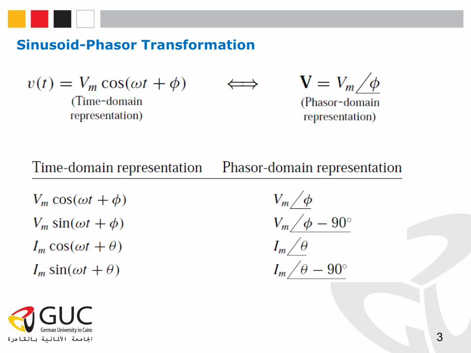
Sinusoid-Phasor Transformation
3
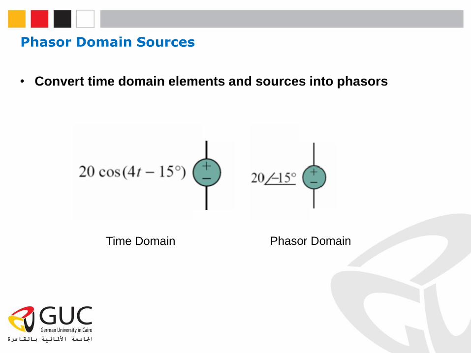
Phasor Domain Sources
• Convert time domain elements and sources into phasors
Time Domain Phasor Domain
Circuit Elements in Frequency Domain
5
VV
i
I
0 t
RV
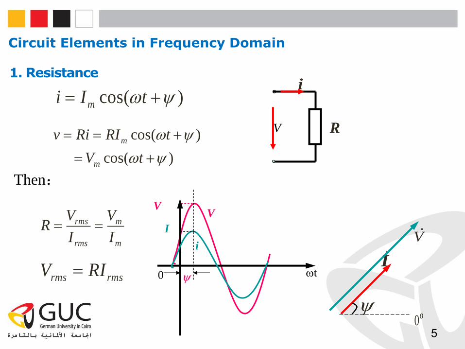
icos( )mi I t
cos( )
cos( )
m
m
v Ri RI t
V t
rms rmsV RI
rms m
rms m
V VR
I I
Then:
1. Resistance
IV
O0
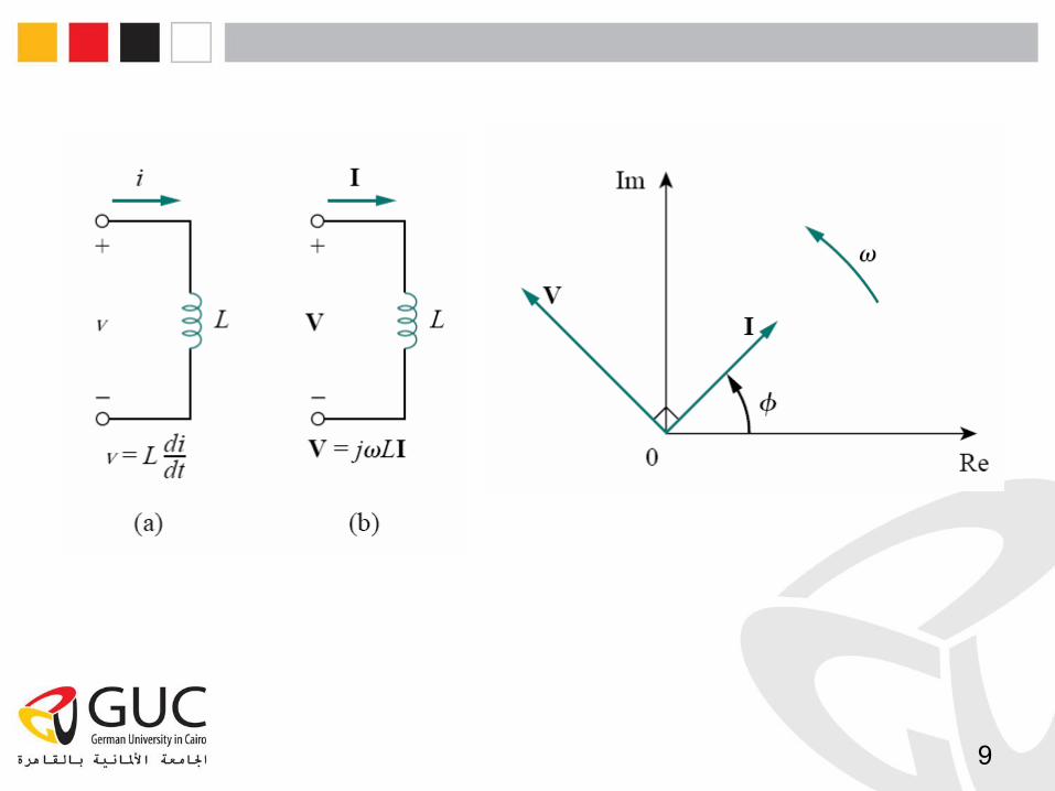
6
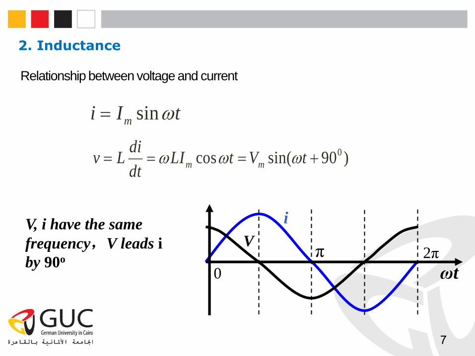
V, i have the same
frequency,V leads i
by 90o
i
Vπ 2π
0 ωt
2. Inductance
7
Relationship between voltage and current
sinmi I t
0cos sin( 90 )m m
div L LI t V t
dt
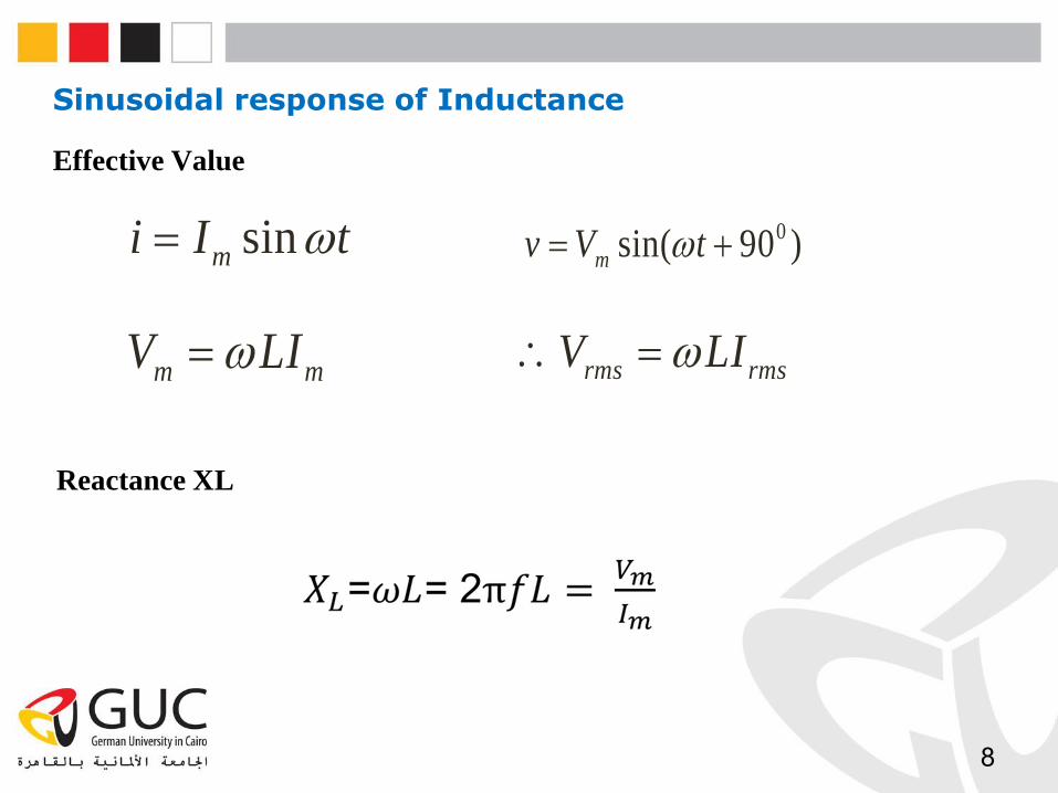
rms rmsV LI m mV LI
Reactance XL
sinmi I t 0sin( 90 )mv V t
Sinusoidal response of Inductance
8
Effective Value
9
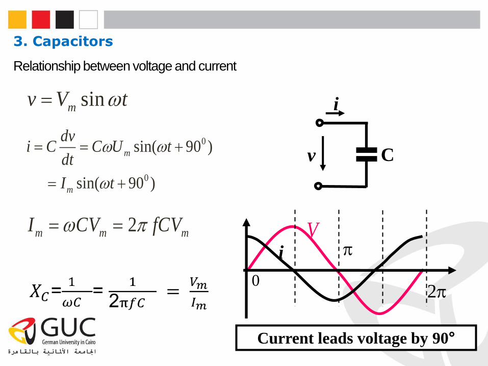
i
v C
sinmv V t
0
0
sin( 90 )
sin( 90 )
m
m
dvi C C U t
dt
I t
Current leads voltage by 90°
2m m mI CV fCV Vi
20
3. Capacitors
Relationship between voltage and current
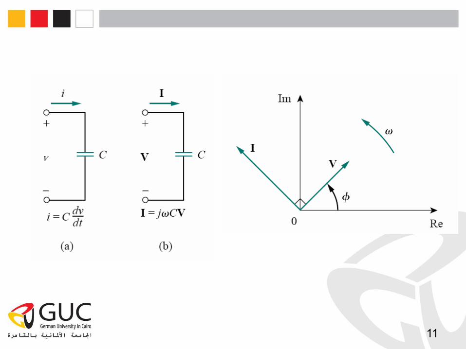
11
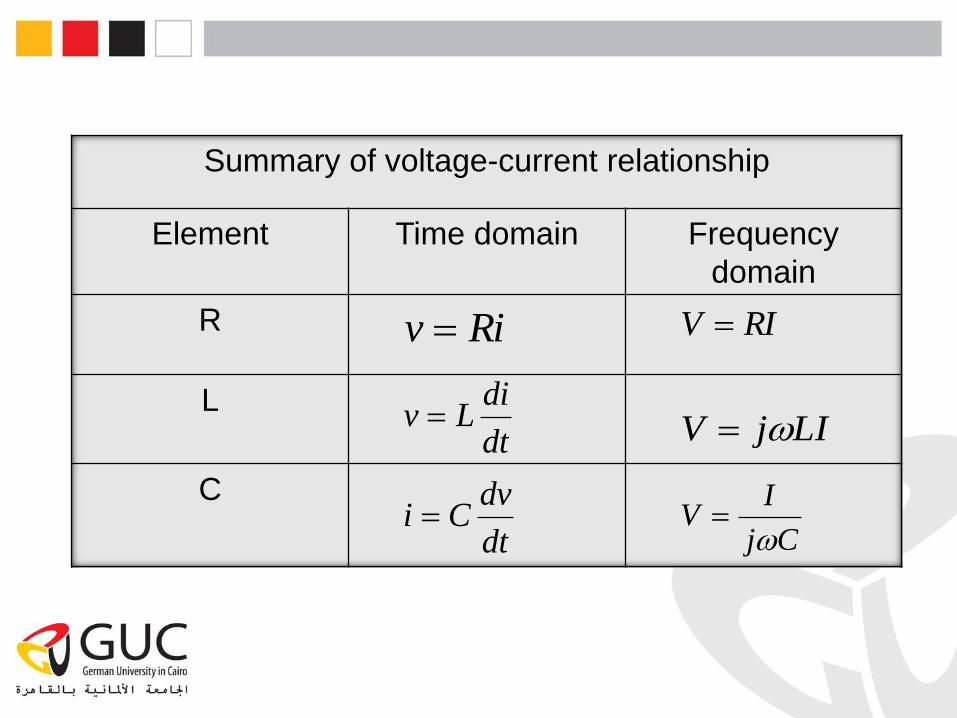
Summary of voltage-current relationship
Element Time domain Frequency
domain
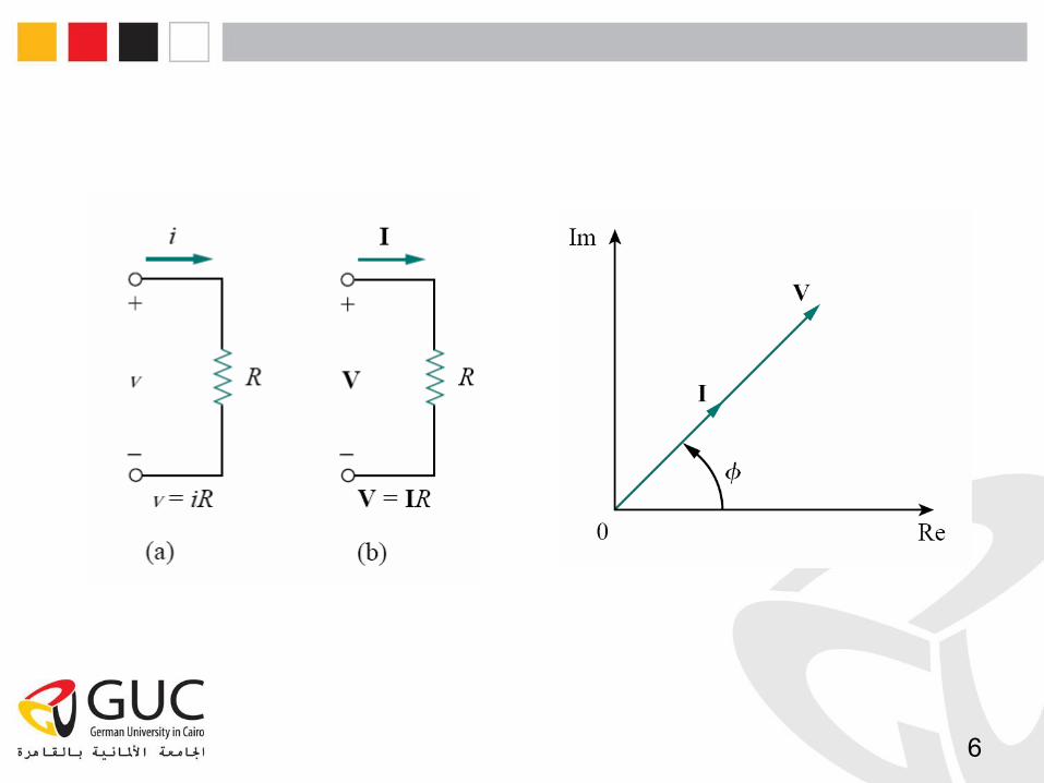
R
L
C
Riv RIV
dt
diLv LIjV
dt
dvCi
Cj
IV
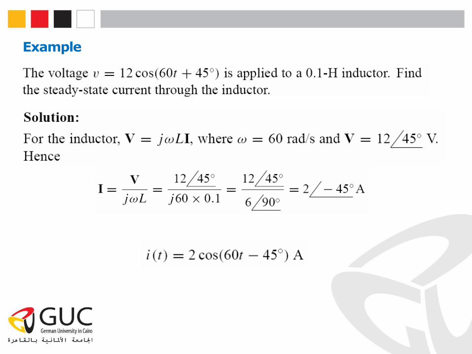
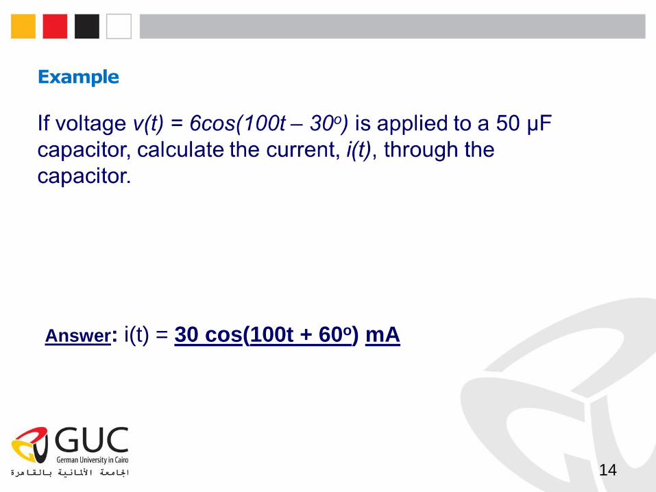
Example
14
Answer: i(t) = 30 cos(100t + 60o) mA
15
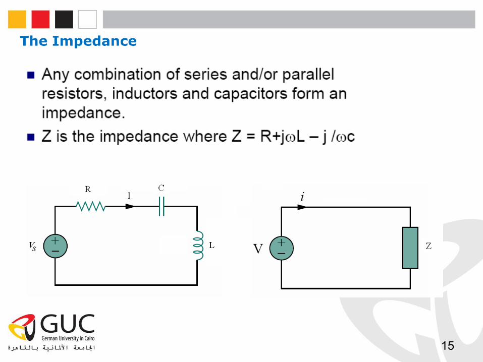
The Impedance
Kirchhoff’s Laws in the Frequency Domain
16
• Both KVL and KCL are hold in the phasor domain or more commonly
called frequency domain.
• Moreover, the variables to be handled are phasors, which are complex
numbers.
• Series and parallel combinations are the same as in D.C. circuits
analysis.
• All the mathematical operations involved are now in complex domain.
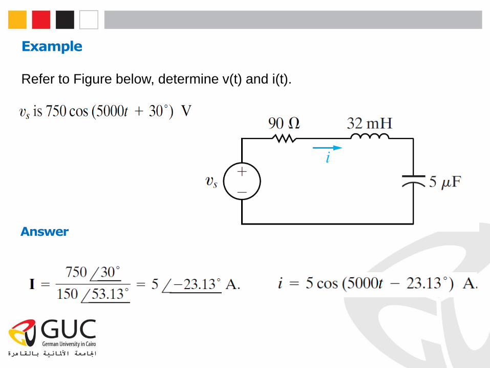
Example
Refer to Figure below, determine v(t) and i(t).
Answer
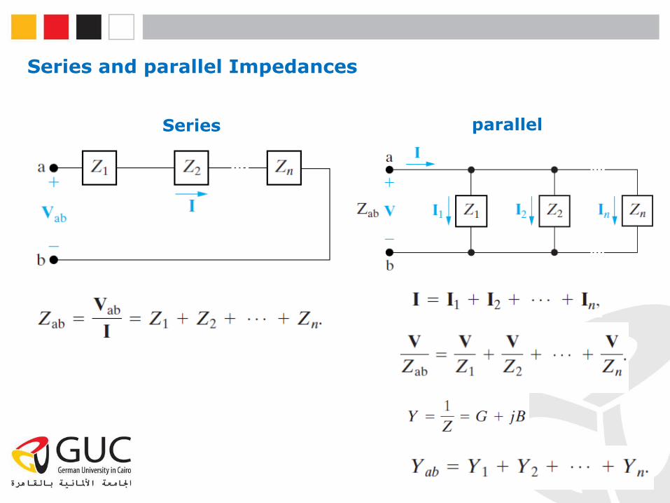
Series and parallel Impedances
Series parallel
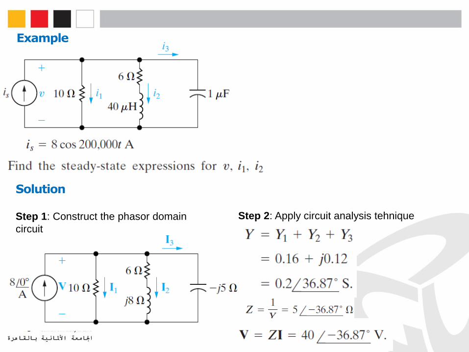
Example
Solution
Step 1: Construct the phasor domain
circuit
Step 2: Apply circuit analysis tehnique
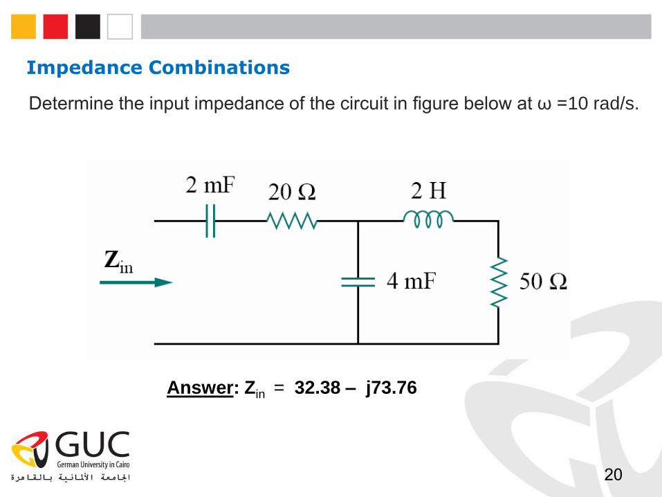
Impedance Combinations
20
Determine the input impedance of the circuit in figure below at ω =10 rad/s.
Answer: Zin = 32.38 – j73.76