Novel Hybrid Flax Reinforced Supersap Composites in Automotive ...

Chapter
Hybrid Steering Systems forAutomotive ApplicationsNicolae Vasiliu, Daniela Vasiliu, Constantin Drăgoi,Constantin Călinoiu and Toma Cojocaru-Greblea
Abstract
The paper presents the results of the researches performed in order to find outthe static and dynamic performances of some recent types of hybrid electrohy-draulic servomechanisms. The new concept was generated by the needs of themodern aerospace technology called “flight by wire”, directed to the use of compactactuators composed mainly by a brushless motor driving a hydrostatic pumpconnected in a close loop with a hydraulic cylinder. The numerical simulationsperformed with Simcenter Amesim language pointed out the possibility of saving alot of energy with this new concept, already used on civil airplanes and fighters. Thenew wave of autonomous driving generated a lot of combinations of electric andhydraulic components, according the peculiarities of applications. The authorsstudied the accuracy of the hybrid steering system of an articulated tractor based ona digital industrial servo valve combined with an ORBITROL standard unit. Thestructure of the last generation of the trucks hybrid steering systems was alsostudied, taking into account the real performances of each component. Finally, theeffect of the strong penetration of the hybrid servo systems in the automotivemanufacturing systems is assessed.
Keywords: energy saving, hybrid electrohydraulic servo systems, modeling,simulation, experimental validation
1. Introduction
The classical electrohydraulic servomechanisms, which include different typesof high-speed two or three-stages servo valves (with flapper - nozzles, jet - pipes orpiezo ceramic actuators) are still widely used in high performance control systemsdue to their very high dynamics reaching even 1000 Hz. However, the complex andexpensive maintenance program, and the low overall energy efficiency due to thelamination of the fluid are strong drawbacks. The maximum efficiency of a classicalhydraulic position servo system is lower than 65%. Consequently, all the advancedfluid control systems include oil coolers, and use special synthetic fluids for widetemperature ranges. In spite of these peculiarities, the modern servo valves offerminor time constants, which allow a high positioning accuracy. In the recent evo-lution of the electrohydraulic servo systems two important structural improve-ments can be pointed out:
a. The replacement of the classical servo valves by proportional directional flowcontrol valves in different industrial applications (Rexroth, from 1989).
1

b. The replacement of any kind of servo valves by a bidirectional reversiblevolumetric pump driven with a brushless motor controlled by powerelectronics (Airbus, from 2005). This evolution is presented in Figure 1 forsymmetric actuators [1, 2]. Figure 2 shows the hydraulic diagram, and themain view of A380 ailerons servos [1, 2].
2. Dynamics of a basic hybrid servomechanism
The assessment of the static and dynamic behavior of a hybrid servomechanismwas performed by numerical simulation using Simcenter Amesim language
Figure 1.Symmetrical structures of classical and hybrid electrohydraulic servos.
Figure 2.Structure of a hybrid servomechanism designed for actuating the ailerons of A380: (a) Basic hydraulic diagram;(b) Main view of assembly.
2
Advanced Applications of Hydrogen and Engineering Systems in the Automotive Industry

produced by SIEMENS PLM Software [3, 4]. The simplified simulation network isshown in Figure 2a. The real hydro mechanical diagram of the system, proposed byProf. J.-Ch. Mare in 2013 [5], shows a much more complex mechatronic system,with a mode selector (active or damping), a differential pressure transducer for themain loop, a rudder angle transducer, some hydraulic resistances modeling thesystem leakages etc. (Figures 3 and 4).
The core of the system is simple, but the whole assembly looks like a F1 hydrau-lic system with nine complex control loops: Power Steering, Gearshift Clutch,Differential, and Reverse gear, DRS, Brake by Wire, Throttle Inlet valves, andTurbo Wastegate. All of them are supplied in close loop by a single Parker swashplate axial pistons pump, pressure compensated! [6].
A simple design [5] based on a DC motor driving a gear pump, and a hydrauliccylinder can reveal both good enough dynamic performances, and some design
Figure 3.Electric drive system and the position loop controller.
Figure 4.Hydraulic section of a complete hybrid servomechanism.
3
Hybrid Steering Systems for Automotive ApplicationsDOI: http://dx.doi.org/10.5772/intechopen.94460

problems involved in the lifetime of a hybrid servomechanism. The time constantcan be easy found using a small voltage step input, for obtaining a piston displace-ment of 1.0 cm from a stroke of 2.5 cm. A reasonable force step input applied on thehydraulic cylinder piston rod can show the system capability to reject commondisturbances. Both events were simulated with Simcenter Amesim language for apump of 1 cc3/rev, reaching 9000 rev/min and 250 bar, driven by a small DC motorof 25 Nm at 270 V and 45 A, with shaft speed sensors used to allow the speedcontrol. The results are presented on the same diagram from Figure 5. The timeconstant of the electro pump is less than 0.25 s, and the piston final position isreached in less than 0.7 s. A piston sudden load variation of 40,000 N generates adrift of about 20% from the nominal value 0f about 80,000N.
Figures 6–8 show the evolution of the main parameters of the pump during thestudied transient.
A sudden aerodynamic load on the aileron can generate a short cavitation periodin the suction line of the pump. This dangerous event is avoided by loading the
Figure 5.Dynamic response for a common position request followed by the rejection of a sudden aerodynamic load:(a) Position request and the piston sliding position; (b) Aileron angular position as a function of time.
4
Advanced Applications of Hydrogen and Engineering Systems in the Automotive Industry

Figure 6.Pump flow rate evolution during the studied transient.
Figure 8.Pump delivery pressure evolution during the studied load transient.
Figure 7.Pressure in the suction port at the beginning of the aerodynamic load.
5
Hybrid Steering Systems for Automotive ApplicationsDOI: http://dx.doi.org/10.5772/intechopen.94460

hydraulic accumulator with nitrogen at 5-6 bar. The compensation of the aerody-namic load applied on the aileron needs a remnant voltage on the armature winding,and a corresponding current (Figures 9 and 10). However, the energy needed forthe studied operation cycle is very low (less than 120 J).
It is useful to study the frequency response of a basic hybrid servomechanism.This task can easy be accomplished using the “transfer meter” block from the“control library” of Simcenter Amesim (Figure 11). A typical result (Figure 12)shows a normal behavior for small amplitude input signals: (a) low auto-oscillationrisk; (b) lower, but dynamic good enough performance for practice.
The studied dynamic model, even simple, gives an overview of the wide facili-ties of the behavioral analysis by simulation. However, in reality, some parts of thesystem should be better considered to get a more predictive representation. Muchmore, the experimental validation of each new component needs a lot of experi-mental researches. The history of the high tech electro hydraulic manufacturers hasshown a huge effort of fine-tuning and implementing new generations of compo-nents and systems [7–9]. Dominque van den Bossche [2] summarized some ofdeveloping stages of this process in close connection with the possible dangeroussituations, which can occur in any flight control systems. Specific maintenanceprograms have to be implemented in all manufacturing process related to theautomotive engineering.
Figure 10.Variation of the input current in the armature winding.
Figure 9.Variation of the input voltage applied to the armature winding.
6
Advanced Applications of Hydrogen and Engineering Systems in the Automotive Industry

The new generation of mechatronic simulation languages reduced drasticallythis effort. The use of the Real Time Simulation with Hardware In-The-Loop accel-erated this process [10–13]. For example, Amesim models can be imported inLabVIEW real time platforms in order to simulate the automotive systems using thegeneral software platform from Figure 13 [10].
A successful hardware implementation of this concept is presented in Figure 14,in order to speed up the design of the new automotive control programs.
The RT simulations with Amesim are frequently used for tailoring differentapplications of the electrohydraulic hybrid servomechanisms. For example, thecomplex steering systems of “Self-Propelled Modular Transporter” as that designedby Mammoet [14] need a RTS of all the path followed during the process. Theindependent propulsion and steering axles are regarded as “super component” inthe simulation network of such a complex vehicle. The RTS platform from
Figure 11.Simulation network for servomechanism frequency response.
Figure 12.Frequency response of a symmetric hybrid servomechanism.
7
Hybrid Steering Systems for Automotive ApplicationsDOI: http://dx.doi.org/10.5772/intechopen.94460

Figure 15, designed by the authors allow the validation of the Amesim simulationsfor different configurations of complex servomechanisms [12, 13].
3. Hybrid steering servomechanisms for tractors
3.1 Modern trends in autonomous driving systems
A modern trend in the agriculture is about making farming processes moreaccurate, efficient, and sustainable with advanced satellite navigation systems (like
Figure 14.RTS test platform created in the Fluid Power Laboratory of U.P.B. for automotive electric transmissions [11]
Figure 13.RTS Platform of Amesim models in LabVIEW RT environment [10]
8
Advanced Applications of Hydrogen and Engineering Systems in the Automotive Industry

GPS) and Information Technology (ITC). Precision Farming is raising the agricul-ture to a new level: doing the right thing, in the right place, the right way, at theright time in the field. Apart from satellite navigation systems, Precision Farmingmakes use of a number of other key technologies [15, 16]. They include automatedsteering systems, which take over specific driving tasks like auto - steering, over-head turning, following field edges and overlapping of rows. On tractors, combineharvesters, maize harvesters and other simulate vehicles there is often a need forelectrically actuated steering to make automatic GPS controlled steering possible. Inaddition, manual steering with variable ratio is an often-wanted feature to improveproductivity and driver comfort. For this purpose, Sauer-Danfoss [17, 18] hasdeveloped a combined steering unit and electro hydraulic steering valve(Figures 16–18) named OSPE: OSP for normal manual steering wheel activated
Figure 15.RTS platform for different complex hybrid servomechanisms.
Figure 16.Hybrid steering module OSPE including both hydromechanical OSP and electrohydraulic proportionalservovalve PVE (Sauer Danfoss).
9
Hybrid Steering Systems for Automotive ApplicationsDOI: http://dx.doi.org/10.5772/intechopen.94460

steering and E for electro hydraulic steering activated by electrical input signaleither from GPS or vehicle controller or from steering wheel sensor (SASA) forvariable steering ratio. In variable steering mode, the electro hydraulic valve partadds flow to the metered out flow from the steering unit part of the OSPE. Thiscombination has built in safety function in form of cut off valve, which makesunintended steering from Electro hydraulic valve part impossible. So OSPE is theright steering element to build up steering system with very high safety level and soto be able to fulfill legislations demands like e.g. in EU Machinery Directive2006/42/EC.
Figure 17.Hybrid steering system for tractors [17, 18].
Figure 18.Electrical and mechanical complex pilot operated steering valve [13].
10
Advanced Applications of Hydrogen and Engineering Systems in the Automotive Industry

On different kind of heavy mobile equipment, as tractors, mobile cranes, self-propelled modular transporter like Mammoet and dedicated mobile systems likefire trucks there is often need for electrically controlled steering either in the formof a joystick, or fully automatic wireless. For such applications Sauer-Danfoss hasdeveloped the pilot operated steering valve type EHPS, which covers a wide rangeof flows by different geometrical spool flow gain (Figure 18).
The above systems turn any tractor in a friendly environment for driver. JohnDeere [19] gives modern examples of ergonomic cabin of the tractor type 8400R(Figure 19).
3.2 Options for a new hybrid steering system
There are some initial decisions to make in order to design a hybrid steeringsystem for any kind of mobile equipment. First, the new system has to allow thehuman operator to drive himself the equipment anytime i.e. to have the highestpriority. Second, the new control system has to be stable and to preserve theaccuracy of the previous one under any operation condition. The electrical compo-nent strongly depends on the electric power supply, rising real problems from thesecurity point of view. Some electrical power supply systems can reduce the risk ofthe electrical systems failure. The main problem is to use the same steering cylinderswith two kinds of hydraulic metering valves. Both of them need to have closecenter, or to be isolated upon the request of the driver by an additive directionalvalve. The relative small fuel consumption introduced by an open centerORBITROL hydraulic steering units can be preserved by driving the input with anelectric actuator like a stepping motor with 100-200 pulses/revolution. This optionneeds a special design of the stepping motor in order to insert it into a steeringcolumn. On the other hand, the use of an open center flow valve leads to a poortracking ability that increases with the steering wheel speed [17]. A typical steadystate diagram of such a hydro mechanical feedback steering unit shows a small forcecapability for high turning speeds. The modern product range has to cover applica-tions of all types of mobile equipment.
This section presents the structure and the performance of a new electro hydraulicsteering system for articulated mobile equipment remote controlled. The new con-cept was designed and tested in the Fluid Power Systems of the University"POLITEHNICA" of Bucharest in order to point out the accuracy and the stability of acontrol solution based on a dual input (digital and analog) IAC-R REXROTH valve
Figure 19.The driving cabin of a modern tractor.
11
Hybrid Steering Systems for Automotive ApplicationsDOI: http://dx.doi.org/10.5772/intechopen.94460

(Figure 20), and a single OBE analog input valve of the same size [20]. The softwareis individually tailored for the different configurations and combinations of the IAC-R valve by standard parameters set in the factory. Settings for the closed-loop andcontrol parameters are done via the bus interface. Several characteristics define thelast generation of electro hydraulic control: fully digitized valve and axis controlelectronics; position and force control of hydraulic axes directly in the valve; variouscontroller functions available (pressure/flow rate, position and alternating control);input of set points, configuration and diagnosis via field bus (depending on the typevia CANopen or Provirus DP). Additional analog set point interface can be used as analternative to set point input via field bus, but the electromagnetic interferences cancreate serious troubles, which need safety requirements according ISO 26262.
The CANbus type of controller area network is best suited for multipoint, longrange cabling in high electromagnetic interferences areas where analog feedbacksignals may fail. This new type of control is widely used in military, automotive andaerospace simulating platforms or other systems where accuracy is very important.The behavior of the servovalve in a digital position-closed loop was identified by theaid a special test platform, which includes a strong elastic component, and a variablemass load (Figures 21 and 22).
Figure 20.High-response valve with integrated digital axis controller (IAC-R) and field bus interface (REXROTH)
Figure 21.Hydraulic diagram of the platform for testing digital servovalves.
12
Advanced Applications of Hydrogen and Engineering Systems in the Automotive Industry

A magnetostrictive digital displacement transducer with SSI interface was usedfor the load. Position reference is set though CANopen bus, and the control algo-rithm is a PID made with the OBE of the digital servo valve. The reference value forthe digital test was generated with the application provided by the manufacturerand sent with a USB<->CANopen adapter. The positioning accuracy depends onthe friction force of the steering cylinder as a function of speed (Figure 23).
Figure 24 shows a typical response of a servomechanism with P controller. Theresponse time of the digital servovalve is very small: about 2 ms for a 10% inputsignal. Consequently, the frequency response is very fast (Figure 25).
The system performances were identified using a forestry articulated tractor(Figure 26) designed as prototype by the research department of the Romaniancompany "PROMEX" from Brăila [22]. The front chassis was locked, leaving freethe back one to rotate on a circular raceway (Figure 27). The tractor steeringsystem was studied by the aid of a rotary hydraulic motor controlled in closedloop by a servovalve (Figure 28). Then, the steering amplifier was replaced by theservovalve itself.
Usually, the control valve of the ORBITROL hydraulic steering unit is designedwith open center for reducing both fuel consumption and steering mechanical
Figure 22.Test platform for identifying the digital servovalve performance [17].
Figure 23.Friction force of the steering cylinder as a function of speed [21].
13
Hybrid Steering Systems for Automotive ApplicationsDOI: http://dx.doi.org/10.5772/intechopen.94460

shocks. The "price" of these gains is a big backlash (Figures 29 and 30) whichincreases with the input frequency [23].
The direct control of the steering angle by a servovalve needs a constant pressuresupply but avoids the backlash (Figures 31 and 32). However, the hysteresis
Figure 25.Frequency response of the servovalve spool position for a sine input of 1.0 V at 50 Hz (given by CANopen).
Figure 24.Typical response of the servomechanism for a P controller with KP = 4.
Figure 26.Overall view of the articulated full hydraulic tractor.
14
Advanced Applications of Hydrogen and Engineering Systems in the Automotive Industry

Figure 27.Plain view of the steering hydraulic cylinders with position transducer.
Figure 28.Hybrid steering servo system driven by an ORBIT motor in close loop: (a) driving system view; (b) rotaryfeedback potentiometer driven by the motor.
Figure 29.Steering system response when ORBITROL unit is driven by a hydraulic motor (Ui = 1.0 V; f = 0,05 Hz).
15
Hybrid Steering Systems for Automotive ApplicationsDOI: http://dx.doi.org/10.5772/intechopen.94460
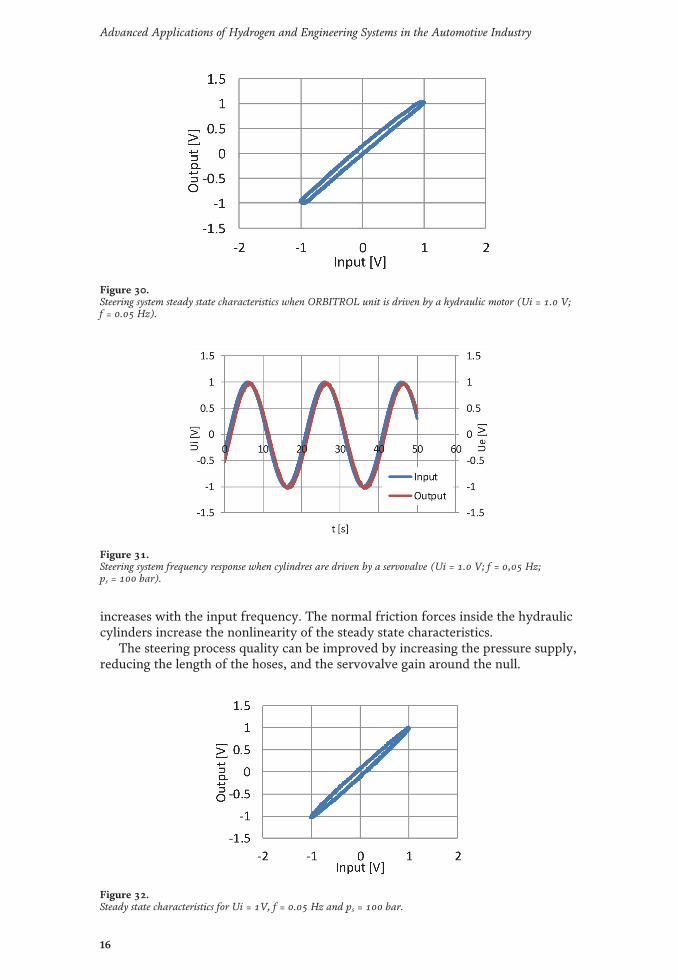
increases with the input frequency. The normal friction forces inside the hydrauliccylinders increase the nonlinearity of the steady state characteristics.
The steering process quality can be improved by increasing the pressure supply,reducing the length of the hoses, and the servovalve gain around the null.
Figure 30.Steering system steady state characteristics when ORBITROL unit is driven by a hydraulic motor (Ui = 1.0 V;f = 0.05 Hz).
Figure 31.Steering system frequency response when cylindres are driven by a servovalve (Ui = 1.0 V; f = 0,05 Hz;ps = 100 bar).
Figure 32.Steady state characteristics for Ui = 1V, f = 0.05 Hz and ps = 100 bar.
16
Advanced Applications of Hydrogen and Engineering Systems in the Automotive Industry

A common stepping motor with battery-less multi-turn absolute encoder can beregarded as a possible electromechanical interface in the ORBITROL steeringsystem, but the size and the weight are too large for the normal input torque(about 10 Nm).
4. Hybrid steering systems for trucks and buses
The high-speed trucks and buses offer an important field of applications to thehybrid servo systems. However, the linear mechanical feedback of the classicalsteering box is still used in modern front axles with independent suspension arms(Figure 33) [24].
A hybrid effect can be introduced by a brushless servomotor placed on thesteering column, or in a mixing box SC, in series with the torsion bar, under theshape of a module with two inputs, which controls the rotary valve (Figure 34).
The rotary valve opening has a high frequency oscillations (Figure 35a), but thesteering process remains continuous (Figure 35b).
The basic rotary steering box of the trucks and buses has the same structure asthe linear one, the only difference coming from the feedback: the piston motion isfed back to the torsion bar with a ball screw (Figure 36). A brushless motor placedin series with the input shaft can control the motion of the rotary valve (Figure 37).
The brushless motor controls the torsion bar by a complex torque and anglesensor composed by Hall sensors and a rotary inductive wheel (Figure 38).
Figure 33.Front axle of a modern truck with linear steering box.
Figure 34.Simcenter Amesim simulation of a hybrid linear steering box [25].
17
Hybrid Steering Systems for Automotive ApplicationsDOI: http://dx.doi.org/10.5772/intechopen.94460

Figure 35.Valve opening and rod displacement for a hydraulic steering system [4]: (a) rotary valve angle opening[degree]; (b) rod displacement [m].
Figure 36.Steering box with ball screw feedback [22].
Figure 37.Hybrid steering box [26].
18
Advanced Applications of Hydrogen and Engineering Systems in the Automotive Industry

A general view of the hybrid system of a Volvo truck shows the minimumchanges needed in the standard version of the car for introducing the hybrid feature(Figure 39).
The HYDRAPULSE Company from U.S.A. introduced a special kind of hybriddriving system. EHSU is a ruggedized electric hydraulic steering pump (electro-hydraulic) unit with integrated motor, controller, and closed-loop feedback that isspecifically designed for mobile steering assist and e-steering applications. TheEHSU (Figure 40) is available in both high and low voltage models and a variety ofpump displacements and power levels. There is no electrical feedback from thesteering arm! [27].
Figure 38.Brushless motor with complex control functions [26].
Figure 39.Components of the hybrid steering system placed in a Volvo truck [26].
19
Hybrid Steering Systems for Automotive ApplicationsDOI: http://dx.doi.org/10.5772/intechopen.94460

5. Conclusions and future research
The basic hydrostatic transmission, composed by a volumetric pump and ahydraulic cylinder remains the most simple, compact and light mechanism forgenerating any force. The combination between a brushless motor, with digitaldriver, and a ball screw connected in close position loop became already the bestdriving system for small inertial loads, but the upper limit of the force remains low.The hybrid combination between a brushless motor and a hydrostatic transmissioncomposed mainly by a high-speed pump, and a linear servomotor offers the bestperformances with the smallest weight and reduced dimensions. In the last decade,
Figure 40.Electrohydraulic hybrid steering systems without direct feedback.
Figure 41.Voith industrial digital hybrid servomechanism [28].
20
Advanced Applications of Hydrogen and Engineering Systems in the Automotive Industry

a significant progress was achieved in promoting this new generation of compactactuators in all the modern industrial manufacturing process, different kind ofsteering system for airplanes, ships, trucks, the control systems for engines, tur-bines, ships, trucks etc. (Figures 41 and 42). The author’s team created a new typeof small power hybrid steering system dedicated to some type of heavy mobilerobots. Figure 43 presents a part of the test platform of the servopump [30]. AFPGA controller was designed for controlling the whole system. The exposure ofthe experimental results overcomes the frame of this paper.
However, some information about the components of the test bench built in theframe of the University POLITEHNICA of Bucharest can be useful for a betterunderstanding of the design problems. An AC Servo Motor & Driver, MINAS A6series produced in 2016 by Panasonic Corporation Motor Business Division waschosen for driving a reversible high-pressure gear pump XR012 from Vivolo Cor-poration.
A PXI industrial device from NI Corporation [20] controls the assembly by theaid of the LabVIEW real time environment. The hydraulic cylinder, designed by theauthors for high mechanical efficiency, includes a tension and compression load cellModel 2712 – 500 from Sensy Company from Belgium; two pressure sensors type7768202 from VIKA Company, and a linear displacement transducer typeMLS130-200-R-N from Penny & Giles Company. Hydac Group and Bosch RexrothGroup supplied the hydraulic circuit components. After the first series of perfor-mance test, a cheaper dedicated controller was designed, and successfully tuned(Figure 44).
Figure 42.Rexroth industrial digital hybrid servomechanism [29].
Figure 43.Servopump for hybrid servomechanisms designed in the Fluid Power Systems Laboratory of U.P.B. [30].
21
Hybrid Steering Systems for Automotive ApplicationsDOI: http://dx.doi.org/10.5772/intechopen.94460

Anyway, the road to a mature industrial design will be a long one, and accordingto Dirk Hartmann and Herman Van der Auweraer from Siemens Corporation, itmust pass through all the stages of the modern manufacturing process called nowDigital Twins [31].
Acknowledgements
We are particularly grateful to Dr. Jan Leuridan, senior vice president in chargeof simulation and test solutions from Siemens PLM Software, a business unit of theSiemens Digital Factory Division. He also serves as CEO for Siemens IndustrySoftware NV. Along 10 years, he helped us to create new hydraulic control systems,and supplied us with high-level software for teaching our students.
Figure 44.Architecture of a configurable embedded controller for hybrid automotive servomechanisms [30].
22
Advanced Applications of Hydrogen and Engineering Systems in the Automotive Industry

Author details
Nicolae Vasiliu*, Daniela Vasiliu, Constantin Drăgoi, Constantin Călinoiuand Toma Cojocaru-GrebleaUniversity POLITEHNICA of Bucharest, Bucharest, Romania
*Address all correspondence to: [email protected]
© 2020TheAuthor(s). Licensee IntechOpen. This chapter is distributed under the termsof theCreativeCommonsAttribution License (http://creativecommons.org/licenses/by/3.0),which permits unrestricted use, distribution, and reproduction in anymedium,provided the original work is properly cited.
23
Hybrid Steering Systems for Automotive ApplicationsDOI: http://dx.doi.org/10.5772/intechopen.94460

References
[1] Xavier Le tron, A380 Flight Controlsoverview, Presentation at HamburgUniversity of Applied Sciences, 27September 2007, http://hamburg.dglr.de.
[2] Dominque van den Bossche, TheA380 Flight Control ElectrohydrostaticActuators, Achievements and LessonsLearnt. In “Proceedings of the 25thInternational Congress of theAeronautical Sciences”, Hamburg,Germany, 3–September 2006, pp. 1–8.
[3] Siemens PLM Software, SimcenterAmesim, Leuven, 2013. Available from:https://www.plm.automation.siemens.com/global/en/products/simcenter/simcenter-amesim.html.
[4] Vasiliu N, Vasiliu D, Călinoiu C,Puhalschi R. Simulation of Fluid PowerSystems with Simcenter Amesim, CRCPress, Taylor &Francis Group, 978-1-4822-5355-9, Boca Raton, FL, USA,2018.
[5] Mare J-Ch. Aerospace Actuators 3,ISTE&WILEY, 978-1-84821-943-4,2018, Hoboken, NJ 07030, USA.
[6] Scarborough C. The fundamentals ofFormula 1 hydraulic systems explained,Motorsport Technology, Availableonline: The%20fundamentals%20of%20Formula%201%20hydraulics%20systems%20explained%20-%20Motorsport%20Technology.html.
[7] Parker, H. Compact EHA—Electro-Hydraulic Actuators for High PowerDensity Applications. 2013. Availableonline: https://goo.gl/t2FMw2.
[8] Rexroth, B. Advantages ofElectrification and DigitalizationTechnology for Hydraulics. 2018.Available online: https://goo.gl/4G6Jxn.
[9] Padovani D., Ketelsen S., HagenD. andSchmidt L. A Self-Contained Electro-Hydraulic Cylinder with Passive Load-
Holding Capability. Energies 2019, 12(2),https://doi.org/10.3390/en12020292.
[10] Vasiliu, C. Real Time Simulation ofthe Automotive ElectricalTransmissions. [PhD thesis]. UniversityPOLITEHNICA of Bucharest; 2011.
[11] Vasiliu, C., Vasile N. Innovative HILArchitecture for Electric PowertrainTesting, U.P.B. Sci. Bull., Series C, Vol.74, Iss. 2, 2012, ISSN 1454-234x.
[12] Puhalschi, R.C. Modeling and RealTime Simulation of the Energy ControlSystems. [PhD thesis]. UniversityPOLITEHNICA of Bucharest; 2013.
[13] Puhalschi, R., Vasiliu D., IonGuță D. D., Mihalescu B. ConcurrentEngineering by Hardware-in-the-loopSimulation with R-T Workshop, 18thEuropean Concurrent EngineeringConference - ECEC'2012, JW MarriottHotel, Bucharest, Romania, April 18-20,p.27-31, 2012, EUROSYS-ETIPublication, ISBN: 978-90-77381-71-7,EAN: 9789077381717.
[14] https://www.mammoet.com/cases/year-round-construction-in-the-arctic/
[15] CEMA-European AgriculturalMachinery Association, PrecisionFarming and Digital Farming. Availableonline: https://www.cemaagri.org/index.php?option=com_content&view=category&id=10&Itemid=152www.cema-agri.org/EuropeanAgriculturalMachinery.
[16] EU Machinery Directive 2006/42/EC. Available online: https://eur-lex.europa.eu/legal-content/EN/TXT/?uri=CELEX:32006L004.
[17] Danfoss. OSPE Steering Valve,Technical Information, July 2020.Available online:https://assets.danfoss.com/documents/DOC348562964075/DOC34856296407.pdf
24
Advanced Applications of Hydrogen and Engineering Systems in the Automotive Industry

[18] Danfoss. Technical Information,EHPS Steering Valve, PVE ActuationModule, OSPCX CN Steering Unit.May 2015. Available online: https://assets.danfoss.com/documents/DOC152886484673/DOC152886484673.pdf
[19] John Deere tractors Series 8400R.Technical Specification. 2020. Availableonline: https://www.deere.com/en/tractors/4wd-track-tractors/
[20] Bosch-Rexroth. 2006. IAC-R valveOperating manual (with CANopen)”,RE 29090-B-01/06.05.
[21] Ganziuc Al. ElectrohydraulicServomechanisms with high ImmunityLevel [PhD thesis]. UniversityPOLITEHNICA of Bucharest; 2013.
[22] Aramă Șt. 1984. Articulate forestrytractor with integral hydrostatictransmission. Romanian Patent 80,316.
[23] Irimia P.C. Researches on the powermanagement of the off-road vehicles[PhD thesis]. UniversityPOLITEHNICA of Bucharest; 2015.
[24] Volvo Bus Corporation. VDS –
Volvo dynamic steering. BED00791.15.10 EN.
[25] Vasile L.N. Researches on theautomotive hydraulic steering systems.[PhD thesis]. UniversityPOLITEHNICA of Bucharest; 2005.
[26] Volvo Truck Corporation. VOLVOFH16 Technical Guide. 2016.
[27] Terzo Power Systems. Electro-Hydraulic Steering Units. 2020.Available online: https://terzopower.com/hydrapulse-ehsu/
[28] https://www.voithturbo.com/hydraulic-systems.
[29] https://www.boschrexroth.com/en/xc/company/press/index2-31936.
[30] Cojocaru-Greblea T. Researches onthe automotive hybrid steering systems.[PhD thesis]. UniversityPOLITEHNICA of Bucharest; 2020.
[31] Hartmann D, Van der Auweraer H.Digital Twins. arXiv:2001.09747v1 [cs.CY] 3 Jan 2020.
25
Hybrid Steering Systems for Automotive ApplicationsDOI: http://dx.doi.org/10.5772/intechopen.94460