CHAPTER ALTERNATING CURRENT - xraykamarul · CHAPTER 6: Alternating Current 6.2 Alternating and...
29
HDR102 SCHOOL OF MEDICAL IMAGING FACULTY OF HEALTH SCIENCES PREPARED BY: MR KAMARUL AMIN BIN ABDULLAH CHAPTER 6 PHYSICS FOR RADIOGRAPHERS 1 ALTERNATING CURRENT
Transcript of CHAPTER ALTERNATING CURRENT - xraykamarul · CHAPTER 6: Alternating Current 6.2 Alternating and...
HDR102
SCHOOL OF MEDICAL IMAGINGFACULTY OF HEALTH SCIENCES
PREPARED BY:MR KAMARUL AMIN BIN ABDULLAH
CHAPTER 6
PHYSICS FOR RADIOGRAPHERS 1
ALTERNATING CURRENT
Slide 2 of 52
TOPIC
CHAPTER 6: Alternating Current
TOPIC
LEARNING OUTCOMES
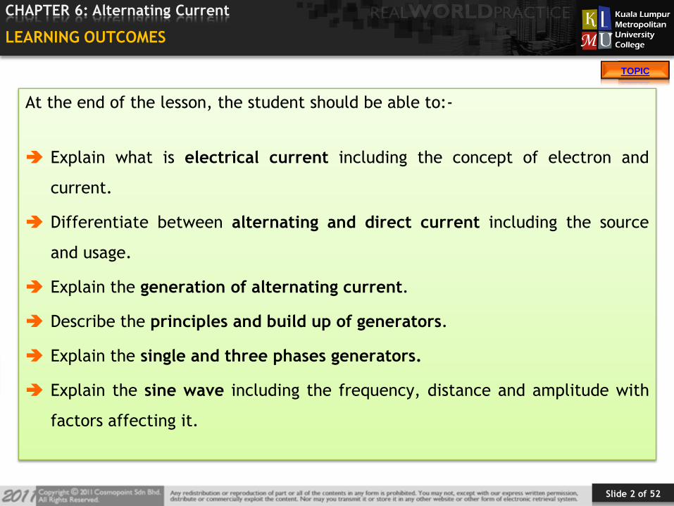
At the end of the lesson, the student should be able to:-
Explain what is electrical current including the concept of electron and
current.
Differentiate between alternating and direct current including the source
and usage.
Explain the generation of alternating current.
Describe the principles and build up of generators.
Explain the single and three phases generators.
Explain the sine wave including the frequency, distance and amplitude with
factors affecting it.
Slide 3 of 52
TOPIC
CHAPTER 6: Alternating Current
TOPIC
TOPIC OUTLINES
INTRODUCTION
6.1 Electrical Current
6.2 Alternating and Direct Current
6.3 The Principles and Build Up of Generators
6.4 Generation of Alternating Current
6.5 One and Three Phases Generators
6.6 Sine Waves
6.3 References
Slide 4 of 52
TOPIC
CHAPTER 6: Alternating Current
TOPIC
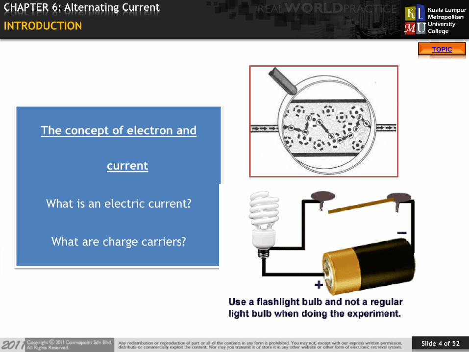
INTRODUCTION
The concept of electron and
current
What is an electric current?
What are charge carriers?
Slide 5 of 52
TOPIC
CHAPTER 6: Alternating Current
TOPIC
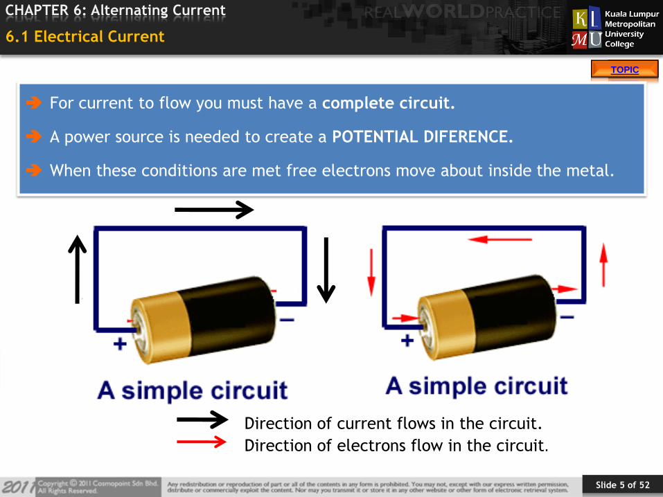
6.1 Electrical Current
For current to flow you must have a complete circuit.
A power source is needed to create a POTENTIAL DIFERENCE.
When these conditions are met free electrons move about inside the metal.
Direction of current flows in the circuit.
Direction of electrons flow in the circuit.
Slide 6 of 52
TOPIC
CHAPTER 6: Alternating Current
TOPIC
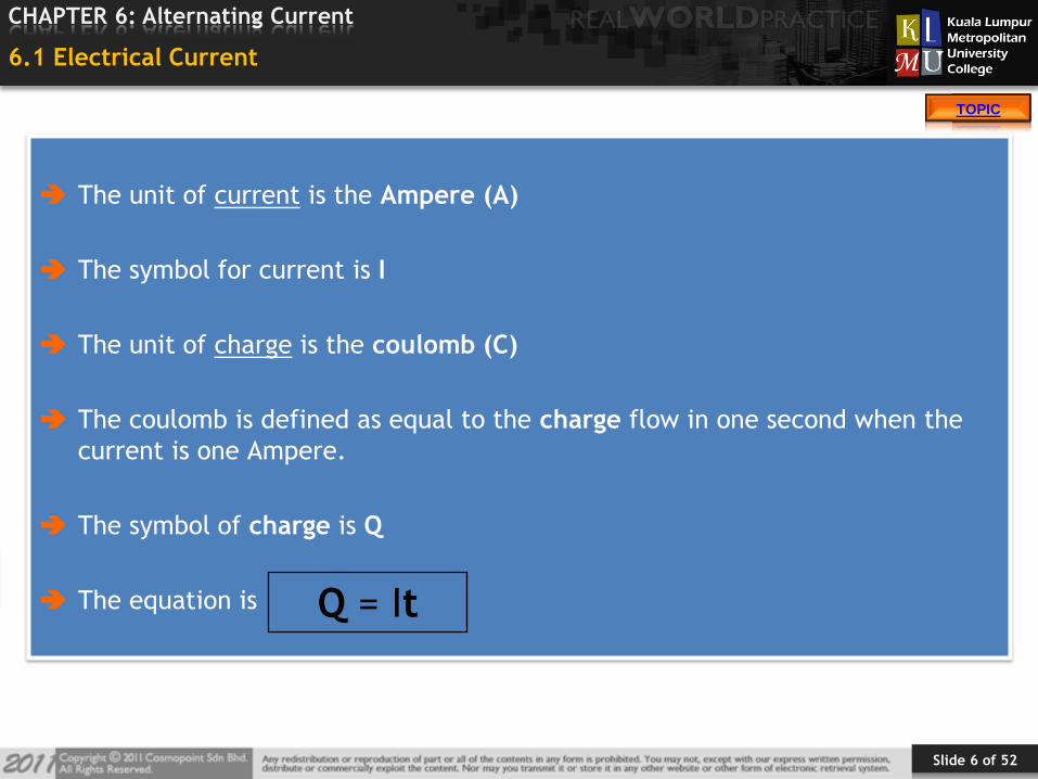
6.1 Electrical Current
The unit of current is the Ampere (A)
The symbol for current is I
The unit of charge is the coulomb (C)
The coulomb is defined as equal to the charge flow in one second when the
current is one Ampere.
The symbol of charge is Q
The equation is Q = It
Slide 7 of 52
TOPIC
CHAPTER 6: Alternating Current
TOPIC
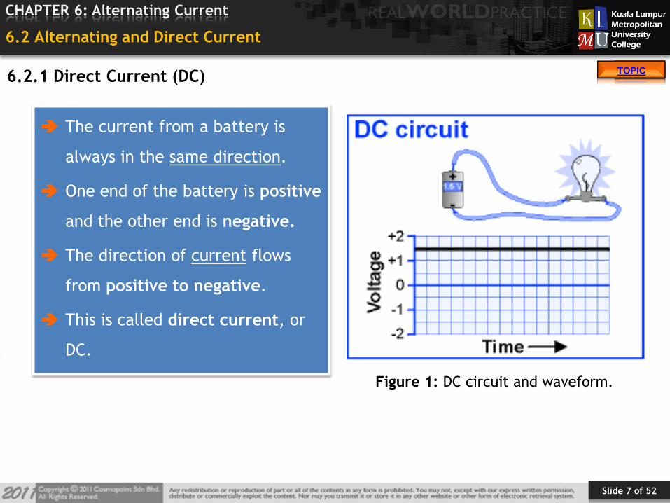
6.2 Alternating and Direct Current
The current from a battery is
always in the same direction.
One end of the battery is positive
and the other end is negative.
The direction of current flows
from positive to negative.
This is called direct current, or
DC.
Figure 1: DC circuit and waveform.
6.2.1 Direct Current (DC)
Slide 8 of 52
TOPIC
CHAPTER 6: Alternating Current
TOPIC
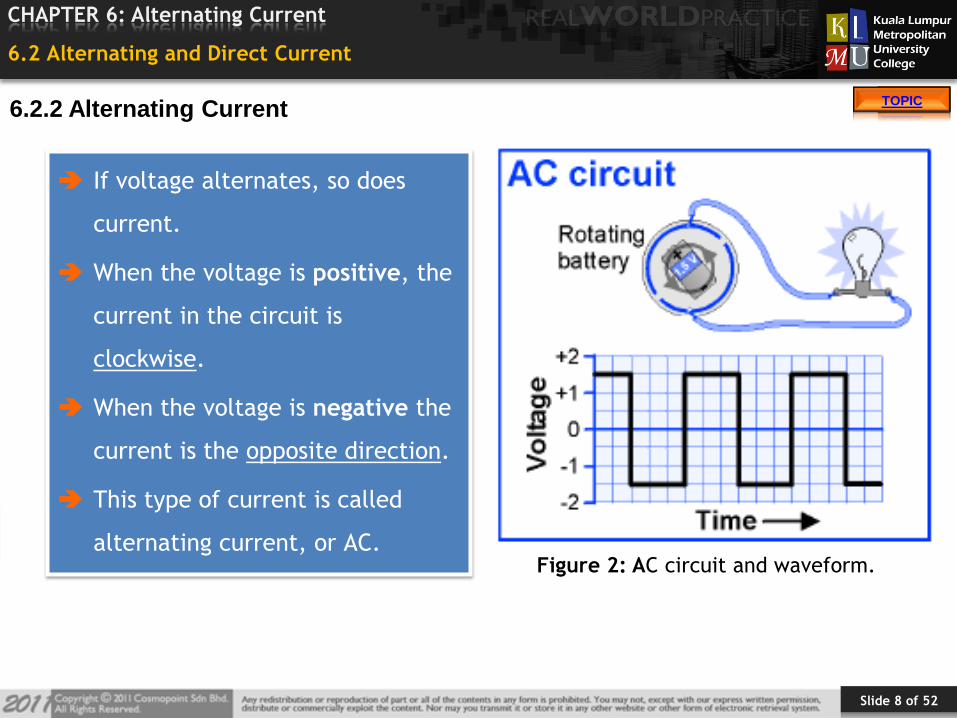
6.2 Alternating and Direct Current
If voltage alternates, so does
current.
When the voltage is positive, the
current in the circuit is
clockwise.
When the voltage is negative the
current is the opposite direction.
This type of current is called
alternating current, or AC.Figure 2: AC circuit and waveform.
6.2.2 Alternating Current
Slide 9 of 52
TOPIC
CHAPTER 6: Alternating Current
TOPIC
6.2 Alternating and Direct Current
AC current is used for almost all high-power applications because it is easier
to generate.
It is cheaper than Direct Current (DC).
It can be transmitted over long distances.
The value of voltage AC can be changed easily, using transformer.
6.2.3 Advantages of Alternating Current (AC)
Slide 10 of 52
TOPIC
CHAPTER 6: Alternating Current
TOPIC
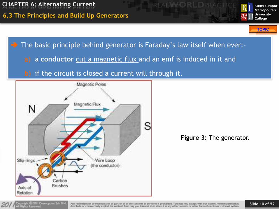
6.3 The Principles and Build Up Generators
The basic principle behind generator is Faraday’s law itself when ever:-
a) a conductor cut a magnetic flux and an emf is induced in it and
b) if the circuit is closed a current will through it.
Figure 3: The generator.
Slide 11 of 52
TOPIC
CHAPTER 6: Alternating Current
TOPIC
6.3 The Principles and Build Up Generators
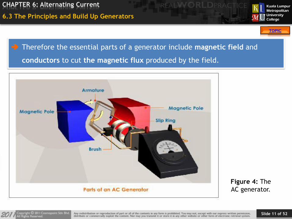
Therefore the essential parts of a generator include magnetic field and
conductors to cut the magnetic flux produced by the field.
Figure 4: The
AC generator.

Slide 12 of 52
TOPIC
CHAPTER 6: Alternating Current
TOPIC
6.4 Generation of AC
A = is moving along (parallel to) the lines of force - cutting NO lines of force,
NO emf is induced.
B = it cuts more and more lines of force per second/ more directly across the
field (lines of force), the emf induced in the conductor is maximum.
Slide 13 of 52
TOPIC
CHAPTER 6: Alternating Current
TOPIC
6.4 Generation of AC
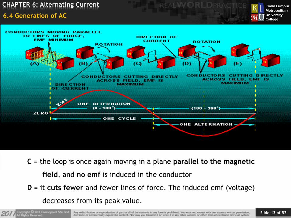
C = the loop is once again moving in a plane parallel to the magnetic
field, and no emf is induced in the conductor
D = it cuts fewer and fewer lines of force. The induced emf (voltage)
decreases from its peak value.
Slide 14 of 52
TOPIC
CHAPTER 6: Alternating Current
TOPIC
6.5 Single and Three Phase Generators
A generator is a device that converts mechanical energy (motion) into
electrical energy (current – voltage).
Slide 15 of 52
TOPIC
CHAPTER 6: Alternating Current
TOPIC
6.5 Single and Three Phase Generators
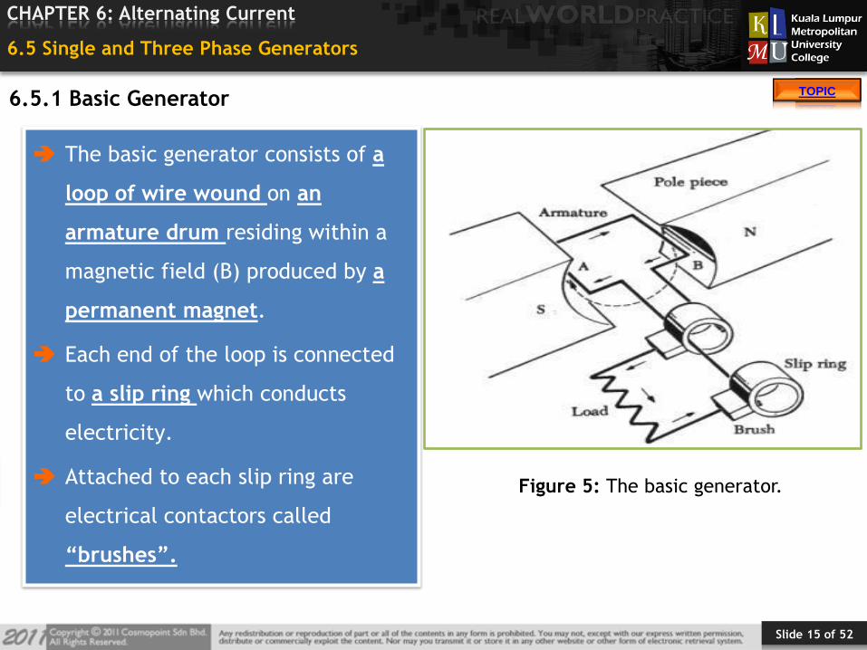
The basic generator consists of a
loop of wire wound on an
armature drum residing within a
magnetic field (B) produced by a
permanent magnet.
Each end of the loop is connected
to a slip ring which conducts
electricity.
Attached to each slip ring are
electrical contactors called
“brushes”.
Figure 5: The basic generator.
6.5.1 Basic Generator
Slide 16 of 52
TOPIC
CHAPTER 6: Alternating Current
TOPIC
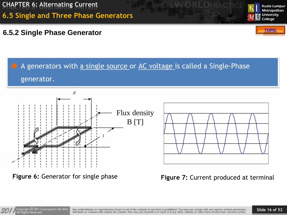
6.5 Single and Three Phase Generators
A generators with a single source or AC voltage is called a Single-Phase
generator.
Flux density
B [T]
l
d
Figure 6: Generator for single phase Figure 7: Current produced at terminal
6.5.2 Single Phase Generator
Slide 17 of 52
TOPIC
CHAPTER 6: Alternating Current
TOPIC
6.5 Single and Three Phase Generators
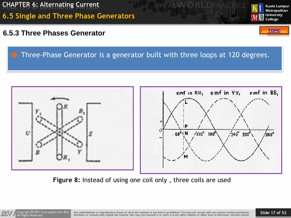
Three-Phase Generator is a generator built with three loops at 120 degrees.
Figure 8: Instead of using one coil only , three coils are used
6.5.3 Three Phases Generator
Slide 18 of 52
TOPIC
CHAPTER 6: Alternating Current
TOPIC
6.6 Sine Waves
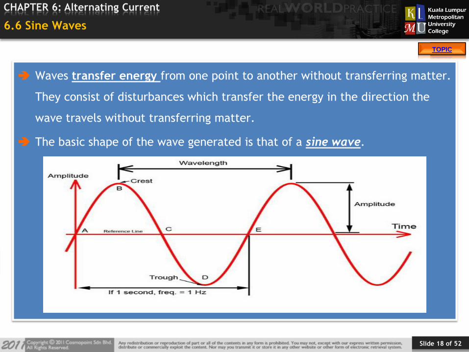
Waves transfer energy from one point to another without transferring matter.
They consist of disturbances which transfer the energy in the direction the
wave travels without transferring matter.
The basic shape of the wave generated is that of a sine wave.
Slide 19 of 52
TOPIC
CHAPTER 6: Alternating Current
TOPIC
6.6 Sine Waves
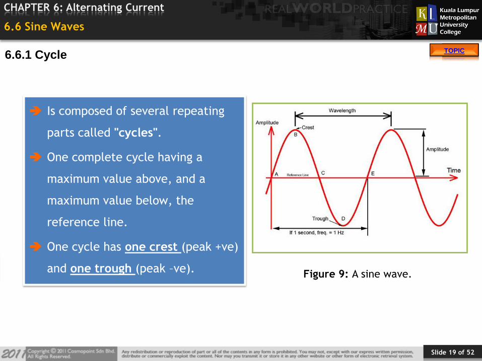
Is composed of several repeating
parts called "cycles".
One complete cycle having a
maximum value above, and a
maximum value below, the
reference line.
One cycle has one crest (peak +ve)
and one trough (peak –ve).Figure 9: A sine wave.
6.6.1 Cycle
Slide 20 of 52
TOPIC
CHAPTER 6: Alternating Current
TOPIC
6.6 Sine Waves
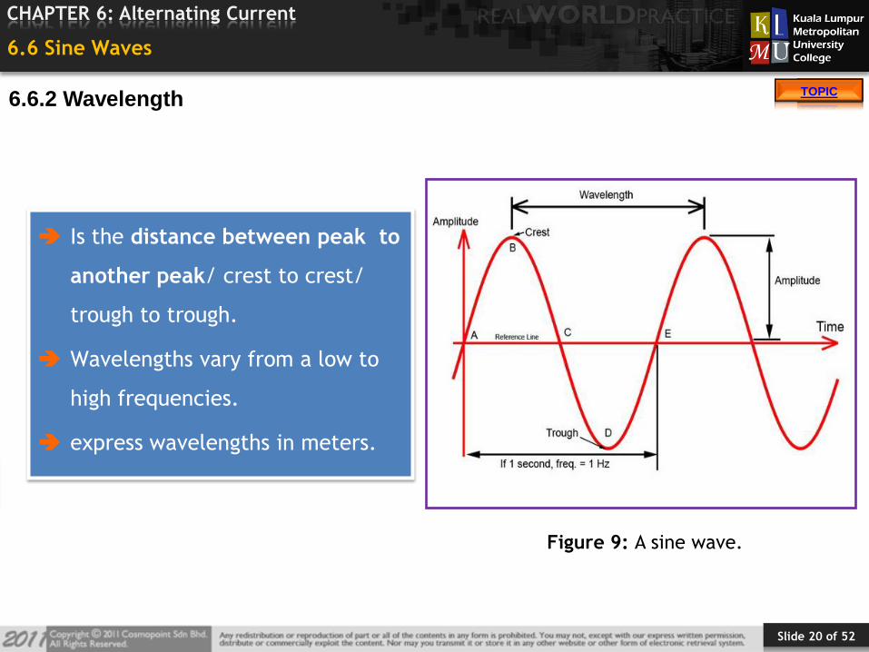
Is the distance between peak to
another peak/ crest to crest/
trough to trough.
Wavelengths vary from a low to
high frequencies.
express wavelengths in meters.
Figure 9: A sine wave.
6.6.2 Wavelength
Slide 21 of 52
TOPIC
CHAPTER 6: Alternating Current
TOPIC
6.6 Sine Waves
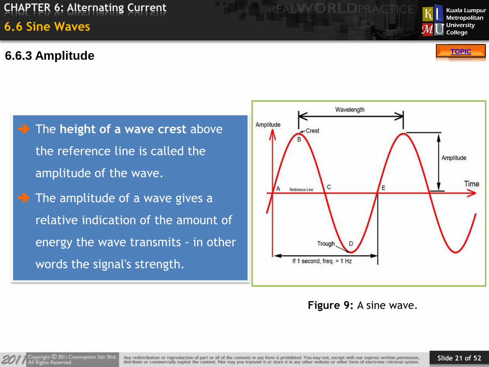
The height of a wave crest above
the reference line is called the
amplitude of the wave.
The amplitude of a wave gives a
relative indication of the amount of
energy the wave transmits - in other
words the signal's strength.
Figure 9: A sine wave.
6.6.3 Amplitude
Slide 22 of 52
TOPIC
CHAPTER 6: Alternating Current
TOPIC
6.6 Sine Waves
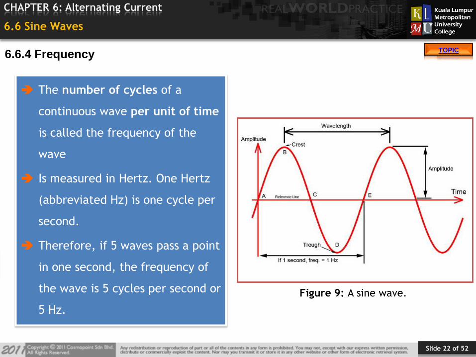
The number of cycles of a
continuous wave per unit of time
is called the frequency of the
wave
Is measured in Hertz. One Hertz
(abbreviated Hz) is one cycle per
second.
Therefore, if 5 waves pass a point
in one second, the frequency of
the wave is 5 cycles per second or
5 Hz.
Figure 9: A sine wave.
6.6.4 Frequency
Slide 23 of 52
TOPIC
CHAPTER 6: Alternating Current
TOPIC
6.6 Sine Waves
Signal attenuation. This is a fancy way of saying, the farther a signal goes, the
weaker it gets. Attenuation can be by absorption, reflection, or refraction of
the radio wave energy.
Interference. The atmosphere is FULL of EM waves of all kind - the more
there are in the area the radio is being used, the more interference there is
and the poorer the range and quality of transmission and reception.
6.6.5 Factors Affecting the Waves
6.6.5.1 Factors that reduce the range include:-
Slide 24 of 52
TOPIC
CHAPTER 6: Alternating Current
TOPIC
6.6 Sine Waves
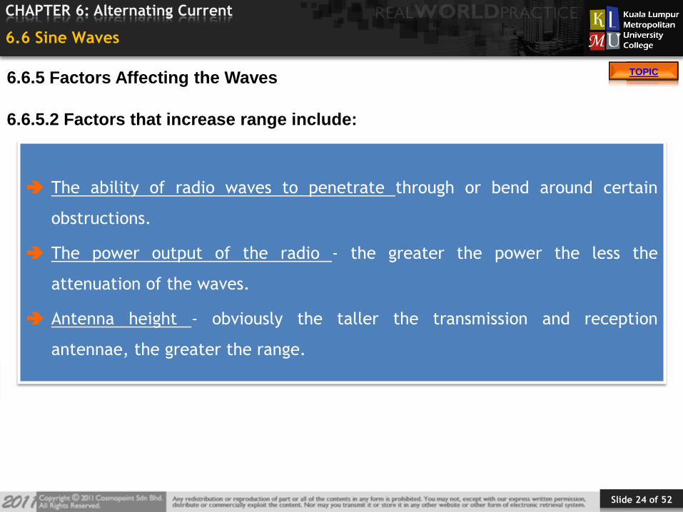
The ability of radio waves to penetrate through or bend around certain
obstructions.
The power output of the radio - the greater the power the less the
attenuation of the waves.
Antenna height - obviously the taller the transmission and reception
antennae, the greater the range.
6.6.5.2 Factors that increase range include:
6.6.5 Factors Affecting the Waves
Slide 25 of 52
TOPIC
CHAPTER 6: Alternating Current
TOPIC
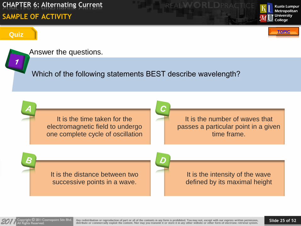
Answer the questions.
SAMPLE OF ACTIVITY
Which of the following statements BEST describe wavelength?
Quiz
It is the time taken for the electromagnetic field to undergo one complete cycle of oscillation
It is the distance between two successive points in a wave.
It is the number of waves that passes a particular point in a given
time frame.
It is the intensity of the wave defined by its maximal height
Slide 30 of 52
TOPIC
CHAPTER 6: Alternating Current
TOPIC
SUMMARY
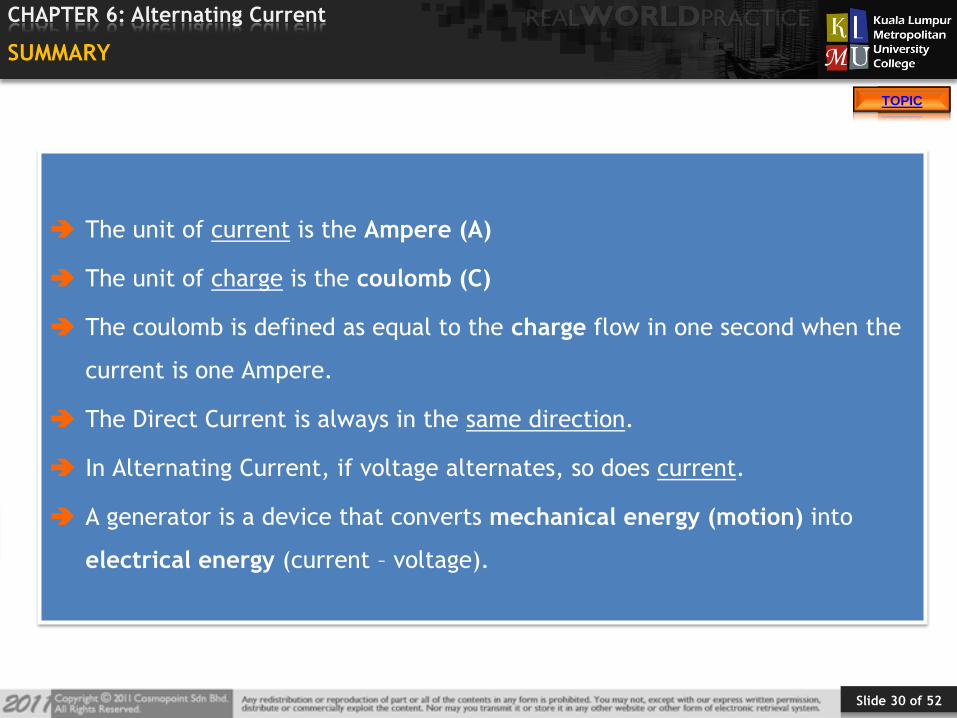
The unit of current is the Ampere (A)
The unit of charge is the coulomb (C)
The coulomb is defined as equal to the charge flow in one second when the
current is one Ampere.
The Direct Current is always in the same direction.
In Alternating Current, if voltage alternates, so does current.
A generator is a device that converts mechanical energy (motion) into
electrical energy (current – voltage).
Slide 31 of 52
TOPIC
CHAPTER 6: Alternating Current
TOPIC
NEXT SESSION PREVIEW
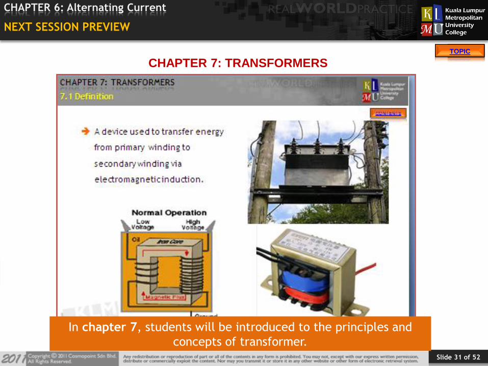
CHAPTER 7: TRANSFORMERS
In chapter 7, students will be introduced to the principles and
concepts of transformer.
Slide 32 of 52
TOPIC
CHAPTER 6: Alternating Current
TOPIC
6.7 References
No. REFERENCES
1 Ball, J., Moore, A. D., & Turner, S. (2008). Essential physics for
radiographers. Blackwell.
2 Bushong, S. C. (2008). Radiologic science for technologists. Canada:
Elsevier.
Slide 33 of 52
TOPIC
CHAPTER 6: Alternating Current
TOPIC
APPENDIX
FIGURE SOURCE
Figure 1 http://www.actors.co.ke/en/news/Energy1.jpg
Figure 2 http://intechweb.files.wordpress.com/2012/03/shutterstock_77399518.jpg
Figure 3 http://www.solarenergybook.org/wp-content/uploads/2009/12/solar-energy-
example.gif
Figure 4 http://www.petervaldivia.com/technology/energy/image/potencial-and-
kinetic.bmp
Figure 5 http://iws.collin.edu/biopage/faculty/mcculloch/1406/outlines/chapter%206/S
B7-2b.JPG
Figure 6 http://www.petervaldivia.com/technology/energy/image/potencial-and-
kinetic.bmp
Figure 7 http://www.physics4kids.com/files/art/motion_energy1_240x180.jpg
Figure 8 http://www.sciencebuilder.com/michigan/science/images/p/potentialenergy.j
pg
Figure 9 http://4.bp.blogspot.com/_V7DuEO3c2E8/S-
b2PZfOXZI/AAAAAAAAADk/KKXoueyon2I/s1600/One-balanced-rock.jpg