Chapter 9jmcgrath/ln.ch9.notes1.pdf · Chapter 9 Gas Power Systems M1A2 Abrams, ... P3 = P2(T3/T2)...
58
Chapter 9 Gas Power Systems M1A2 Abrams, with current and proposed 1500 hp turbine engine. Photos courtesy of United States Military Academy
-
Upload
nguyenkhuong -
Category
Documents
-
view
250 -
download
0
Transcript of Chapter 9jmcgrath/ln.ch9.notes1.pdf · Chapter 9 Gas Power Systems M1A2 Abrams, ... P3 = P2(T3/T2)...

Chapter 9
Gas Power SystemsM1A2 Abrams, with current and proposed 1500 hp turbine engine. Photos courtesy of United States Military Academy

ENGINEERING CONTEXTThe vapor power systems studied in Chap. 8 use working fluids that are
alternately vaporized and condensed. The objective of the present chapter is to study power systems utilizing working fluids that are always a gas. Included in this group are gas turbines and internal combustion engines of the spark-
ignition and compression-ignition types. In the first part of the chapter, internal combustion engines are considered. Gas turbine power plants are discussed in the second part of the chapter. The chapter concludes with a brief study of
compressible flow in nozzles and diffusers, which are components in gas turbines for aircraft propulsion and other devices of practical importance.

Piston-Cylinder Engines
4 Stroke Engine Process
• *Intake Stroke
• Compression Stroke
• Power Stroke (Expansion)
• Exhaust Stroke
* For Spark Ignition engines, intake is of an air/fuel mixture. For Diesel engines, intake is air only.

Compression Ratio, rr = [Volume (BDC) / Volume (TDC)] > 1
Mean Effective Pressure, mep
Mep = Net work for one cycle/Displacement Volume

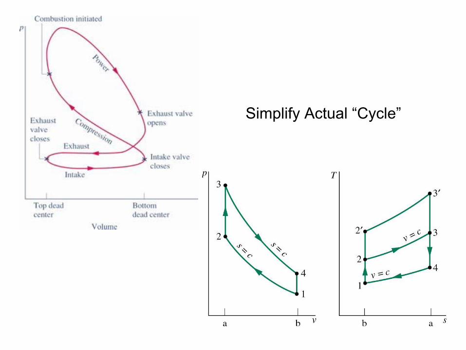
Simplify Actual “Cycle”

• Process 1–2 is an isentropic compression of the air as the piston moves from bottom dead center to top dead center.
• Process 2–3 is a constant-volume heat transfer to the air from an external source while the piston is at top dead center. This process is intended to represent the ignition of the fuel–air mixture and the subsequent rapid burning.
• Process 3–4 is an isentropic expansion (power stroke).
• Process 4–1 completes the cycle by a constant-volume process in which heat is rejected from the air while the piston is at bottom dead center.
Otto Cycle

Air Standard AnalysisThe following assumptions are made:• Air, an Ideal Gas, is the working fluid• Combustion is replaced with Heat
Addition (see Chap 13 for details)
• No exhaust and intake strokes –constant volume heat rejection
• All processes are internally reversible(Q ~ T-S area & W ~ P-V area)
For Cold-Air Standard, Specific Heats are also assumed constant

Cycle Analysis

PG Region:Far from Dome

• Process 1–2 is an isentropic compression of the air as the piston moves from bottom dead center to top dead center.
Q12
W12
Q12
W12
012 12 2 1( )Q W E m u u+ = ∆ = −
122 1( )W u u
m= −
Note: Work convention non-standard
1
2
Isentropic => Adiabatic, Reversible
In = Stored + Out

Q23
W23
23 23 3 2( )Q W E m u u+ = ∆ = −0
233 2( )Q u u
m= −
• Process 2–3 is a constant-volume heat transfer to the air from an external source while the piston is at top dead center. This process is intended to represent the ignition of the fuel–air mixture and the subsequent rapid burning.
2 3 Constant Volume: dV = dv = 0
In = Stored + Out

• Process 3–4 is an isentropic expansion (power stroke).
Q34
W34
Q34
W34
34 34 4 3 34( )Q E W m u u W= ∆ + = − +0
343 4( )W u u
m= −
Note: Work convention is standard
3
4
Isentropic => Adiabatic, Reversible
In = Stored + Out

• Process 4–1 completes the cycle by a constant-volume process in which heat is rejected from the air while the piston is at bottom dead center.
414 1( )Q u u
m= −
Q41
W41
In = Stored + Out
41 41 1 4 410 ( )E Q W m u u Q= ∆ + + = − +0
4 1Constant Volume: dV = dv = 0

PowerPoint frozen? Click here and try again

Otto Cycle
4 Internally Reversible Processes:• Isentropic Compression• Constant Volume Heat Addition• Isentropic Expansion• Constant Volume Heat Rejection
*Cycle Analysis:
121 2
W u um
= −
343 4
W u um
= −
233 2
Q u um
= −
411 4
Q u um
= −
* Sign Conventions (Work in negative, etc.) are sometimes changed for cycle applications

Analysis & Performance Parameters
( ) ( )34 123 4 2 1
cycleW W W u u u um m m
= − = − − −
( ) ( )( )
3 4 2 134 12 4 1
3 2 3 2
1net
in in
u u u uW W W u uQ Q u u u u
η− − −− −
= = = = −− −
( ) ( )23 413 2 4 1
cycleW Q Q u u u um m m
= − = − − −
4 1
3 2
1 u uu u
η −= −
−

How would these equations be used?
Working fluid is Air- assumed to behave as an Ideal Gas
Ideal Gas Review given in Table 9.1
Works, Heat Transfers & Thermal Efficiency: based on u values
Internal energy (U, u) is only a function of T for ideal gas
Make use of isentropic relations for Ideal Gas for two processes

Apply Air Standard Otto Cycle Analysis
Here the temperature dependence of the specific heats is accounted for by using Table A22 or A22E

Typical Problem-Solving ApproachKnow the inlet pressure and temperature: get u1 and vr1
Know compression ratio, r = V2/V1 = vr2/vr1
Process 1 -> 2 isentropic: Table A22- get vr2, T2 and u2
Use PV = mRT to get P2: P2 = P1(T2/T1)(V1/V2)
V3 = V2, so use PV= mRT to get P3: P3 = P2(T3/T2)
Know maximum temperature, T3: Table A22- get u3 and vr3
Process 3 -> 4 isentropic: get vr4, T4 and u4
All W, Q and thermal efficiency in terms of known u’s
m = PV/RT
Mep = Wcycle/(V1 – V2)
Note: Temperature dependence of Cp & Cv accounted for

When specific heats can be assumed constant we applythe so-called Cold Air-Standard Analysis
In this case simple isentropic relations for PG are used instead of Table A22 or A22E

Typical Problem-Solving ApproachKnow the inlet pressure and temperature: get u1
Know compression ratio, r = V2/V1 = V4/V3
Process 1 -> 2 isentropic: T2/T1= (V1/V2)^k-1 = r^(k-1)gets T2 and u2
Use PV = mRT to get P2: P2 = P1(T2/T1)(V1/V2)
V3 = V2, so use PV= mRT to get P3: P3 = P2(T3/T2)
Know maximum temperature, T3: Table A22- get u3
Process 3 -> 4 isentropic: T4/T3= (V3/V4)^k-1 = 1/(r^(k-1))gets T4 and u4
All W, Q and thermal efficiency in terms of known u’s
m = PV/RT Mep = Wcycle/(V1 – V2)

Effect of Compression Ratio, ron Performance
Increasing the Compression Ratio Increases Average Temperature of Heat Addition with Same Heat Rejection Temperature Will Increase the Thermal Efficiency
3’
2’ 3
2

( )( )4 1
3 2
1 v
v
c T Tc T T
η−
= −−
( )( )
4 1
3 2
1u uu u
η−
= −−
41
1
32
2
11
1
TTTTTT
η
−
= −
−
34
1 2
TTT T
= 1
2
1 TT
η = −
1
1 11
2 2
1k
k
T VT V r
−
−
= =
1
11 krη −= −
Define: Thus:
Algebra to: Where s= const: And:
1
341
3 4
1k
k
VTT V r
−
−
= =
Thus:
p
v
ck
c=
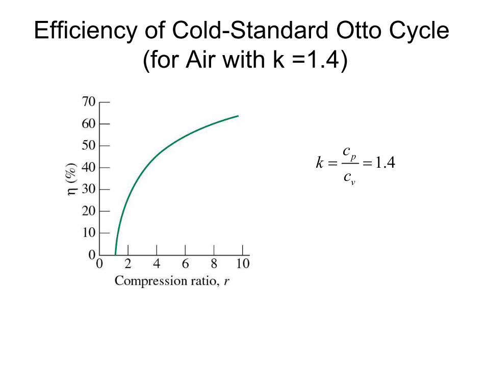
1.4p
v
ck
c= =
Efficiency of Cold-Standard Otto Cycle (for Air with k =1.4)

Analysis & Performance Parameters
Air Standard Analysis Cold Air Standard Analysis
12
rr
vvr
=12
1
kT rT
−=
4 3r rv rv= 41
3
1k
TT r −=
1
11 krη −= −
4 1
3 2
1 u uu u
η −= −
−

Diesel Cycles
4 Internally Reversible Processes:• Isentropic Compression• Constant Pressure Heat Addition• Isentropic Expansion• Constant Volume Heat Rejection
*Cycle Analysis:
121 2
W u um
= −
343 4
W u um
= −
233 2
Q h hm
= −
411 4
Q u um
= −
( )232 3 2
W P v vm
= −

Diesel CyclesDiffers from Otto (Spark Ignition Cycle) by model for heat addition
For Diesel it is constant Pressure rather than constant Volume
Diesel Otto

Leads to Difference in T-S Diagram
Diesel Otto

Cycle Analysis

( )3
232 3 2
2
W Pdv P v vm
= = −∫ ( )3 2 23 23m u u Q W− = −
( ) ( ) ( )233 2 2 3 2 3 2 3 3 2 2
Q u u P v v u u Pv P vm
= − + − = − + −
( )233 2
Q h hm
= − ( )414 1
Q u um
= −
( )( )
4 1
3 2
1u uu u
η−
= −−
( )( )
414 1
23 23 3 2
1 1cycleW Q
u um mQ Q h hm m
η−
= = − = −−

Thermal Efficiency Increases with Compression Ratio
Need properties at all states to calculate efficiencyThis means we need temperatures at all states
Assume we know T1 (vr1) and compression ratio, r 1
2
VrV
=
( ) 22 2 1 1
1
1r r r
Vv T v vV r
= =To get T2 (u2, h2):
To get T3 (u3, h3): PV mRT=
3 3
3 3
2 22 2
PVT VmR
PVT VmR
= =
3 2P P=
And Cut-Off Ratio, defined as: 3
2cVrV
=
33 2 2
2c
VT T r TV
= =
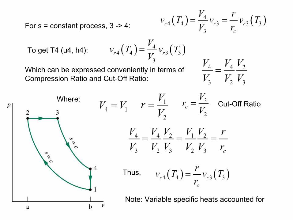
For s = constant process, 3 -> 4:
( ) ( )44 4 3 3
3r r
Vv T v TV
=To get T4 (u4, h4):
Which can be expressed conveniently in terms of Compression Ratio and Cut-Off Ratio:
( ) ( )44 4 3 3 3
3r r r
c
V rv T v v TV r
= =
4 4 2 1 2
3 2 3 2 3 c
V V V V V rV V V V V r
= = =
4 4 2
3 2 3
V V VV V V
=
4 1V V= 1
2
VrV
= 3
2cVrV
= Cut-Off RatioWhere:
( ) ( )4 4 3 3r rc
rv T v Tr
=Thus,
Note: Variable specific heats accounted for

If Constant Specific Heats Is Assumed:Cold Air-Standard Analysis
Assume we know T1 and compression ratio, r 1
2
VrV
=
And Cut-Off Ratio, defined as: 3
2cVrV
=
112 1
1 2
kkT V r
T V
−
− = =
T2, h2, u2 known
33 2 2
2c
VT T r TV
= = T3, h3, u3 knownFrom PG:
1 134
3 4
k kcV rT
T V r
− − = =
T4, h4, u4 known

( )1
1111
kc
kc
rr k r
η −
−= − −
Effect of Compression Ratio on Performance
Use of Simple Cold Air-Standard Analysis Defines Basic Performance
k is constant
Diesel:
Otto:
1
11 krη −= −
Thus, for same compression ratio,the efficiency of Otto cycle superior to that of Diesel cycle

Analysis & Performance Parameters
Air Standard Analysis Cold Air Standard Analysis
12
rr
vvr
= 12
1
kT rT
−=
4 3r rc
rv vr
=
1
4
3
k
cT rT r
−
=
( )1
1 111
kc
kc
rr k r
η −
−= − −
4 1
3 2
1 u uh h
η −= −
−
3 2cT r T=
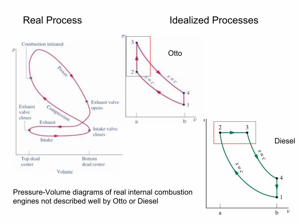
Real Process Idealized Processes
Diesel
Otto
Pressure-Volume diagrams of real internal combustionengines not described well by Otto or Diesel

Introduce the Air-Standard Dual CycleThe Dual Cycle is a combination in sense that Heat Addition is modeled as occurring in two steps, Constant-Volume, then Constant-Pressure

Dual Cycle
5 Internally Reversible Processes:• Isentropic Compression• Constant Volume Heat Addition • Constant Pressure Heat Addition• Isentropic Expansion• Constant Volume Heat Rejection
*Cycle Analysis:
121 2
W u um
= −
344 3
Q h hm
= −
233 2
Q u um
= −
511 5
Q u um
= −
( )343 4 3
W P v vm
= −
454 5
W u um
= −
( ) ( )5 1
3 2 4 3
1 u uu u h h
η −= −
− + −

Turbojet-powered Raptor fighter aircraft
21 MW

Gas Turbines
Assumptions for the basic gas turbine cycle:• Air, as an ideal gas, is the working fluid throughout• Combustion is replaced with heat transfer from an external source
Open System Closed System

PowerPoint frozen? Click here and try again

The Air-Standard Brayton CycleCycle Analysis:
121 2
W h hm
•
• = −
233 2
Q h hm
•
• = −
411 4
Q h hm
•
• = −
343 4
W h hm
•
• = −
Compressor & Turbine Assumed Adiabatic

( ) ( )( )
3 4 2 1
3 2
CT
in
WWh h h hm m
Q h hm
η− − − −
= =−
( )( )
2 1
3 4
C
T
Wh hm
bwrh hW
m
− = =
−
Typical bwr of gas turbines is 40% to 80%Compared to 1 or 2% for vapor power cycles (Rankine)
If temperatures are known at all states, then A22 (or A22E) can be used to get specific enthalpies
ORCold Standard-Air analysis with constant specific heats used

Ideal Brayton CycleAssume that Irreversibilities are Not Present for Ideal Engine
1 to 2: Rev, Adiabatic (Isentropic) Compression2 to 3: Reversible, Isobaric Heating3 to 4: Rev, Adiabatic (Isentropic) Expansion4 to 1: Reversible, Isobaric Cooling

Recall Work Expression and Representation for mass passing through a control volume (Open System)
Internally Reversible Process
2
1Re
CV
Int v
W vdPm
= −
∫
Remember the difference between this and Closed System
2
121
W PdV= ∫

Ideal Brayton CycleAssume that Irreversibilities are Not Present for Ideal Engine
1 to 2: Rev, Adiabatic (Isentropic) CompressionWork is area: 1-2-a-b-1
3 to 4: Rev, Adiabatic (Isentropic) ExpansionWork is area: 3-4-b-a-3

Ideal Brayton CycleAssume that Irreversibilities are Not Present for Ideal Engine
1 to 2: Rev, Adiabatic (Isentropic) Compression2 to 3: Reversible, Isobaric Heating3 to 4: Rev, Adiabatic (Isentropic) Expansion4 to 1: Reversible, Isobaric Cooling

Area Representation of Heat Transfer

Ideal Brayton CycleAssume that Irreversibilities are Not Present for Ideal Engine
2 to 3: Reversible, Isobaric HeatingHeat Transfer Added is Area 2-3-a-b-2
4 to 1: Reversible, Isobaric CoolingHeat Transfer Removed is Area 1-4-a-b-1

Cycle Analysis

Ideal Brayton CycleAssume that Irreversibilities are Not Present for Ideal Engine
Typical case, knowns are: T1, P1, Compressor pressure Ratio and turbine inlet temperature, T3

We know T1, Compressor ratio (P2/P1) and that Process 1 -> 2 is isentropic:
( ) ( ) 22 2 1 1
1r r
Pp T p TP
= Defines T2, u2, h2
We know T3, and that Process 3 -> 4 is isentropic:
( ) ( ) 44 4 3 3
3r r
Pp T p TP
= But, 2 3P P= 1 4P P=
Therefore,
( ) ( )4 14 4 3 3 3
3 2r r r
P Pp T p p TP P
= =
Defines T4, u4, h4
Defines u1, h1
Defines u3, h3
Accounts for temperature Dependence of specific heats

When Specific Heats Can Be Assumed Constant:Cold Air-Standard Basis Analysis
1
22 1
1
kkPT T
P
−
=
Where pressure ratio and k are knownSo all properties are known for state 2
1 1
4 14 3 3
3 2
k kk kP PT T T
P P
− −
= =
Where T3, pressure ratio and k are knownSo all properties are known for state 4
T1 and T3 are known, so all properties are known at states 1 and 3

Effect of Compressor Ratio onIdeal Brayton Cycle
Higher Compression to 2’ and 3’Opens up area and IncreasesThermal Efficiency

Gas Turbine Irreversibilities and LossesFriction produces entropy in Heat Exchangers (not large)
Friction produces entropy In Compressor & Turbine(Important)
Isentropic efficiencies of80% to 90% possible inCompressors & Turbines
Entropy generation in the Combustion process is mostsignificant (Chapter 13)
( )( )
3 4
3 4
T
TsT
s
Wh hmh hW
m
η
− = =
−
( )( )2 1
2 1
c
ssc
c
Wm h h
h hWm
η
− = =
−

In actual case, pressure drops and friction occur in both heat exchangers, the compressor and the turbine
In model case, assume no pressure drops in heat exchangers. Include entropy generation in the compressor and turbine. Use isentropic efficiencies

END


![0) · 2016. 7. 8. · x\hsp[`th`]hy`klwlukpunvu svjh[pvu ;opz^psshhlj[Äuhs lhkpunz ... pj /\tpjhjpk)sluk-sv^ly luohujly t3 t3 t3 t3 t3 t3 t3 t3 t3 t3 t3 t3 t3 t3 t3 t3 t3 t3 t3 t3](https://static.fdocuments.net/doc/165x107/60d98d4a31005a4c8d3c5fa4/0-2016-7-8-xhspthhyklwlukpunvu-svjhpvu-opzpsshhljuhs-lhkpunz-.jpg)