
Chapter 9: Ideal Transformer - Oakland...
14
10/9/2003 Electromechanical Dynamics 1 Chapter 9: Ideal Transformer
Transcript of Chapter 9: Ideal Transformer - Oakland...
10/9/2003 Electromechanical Dynamics 1
Chapter 9: Ideal Transformer
10/9/2003 Electromechanical Dynamics 2
Introduction
• Transformers are one of the most useful electrical devices– provides a change in voltage and current levels
– provides galvanic isolation between different electrical circuits
– changes the apparent magnitude value of an impedance
10/9/2003 Electromechanical Dynamics 3
Voltage Induction
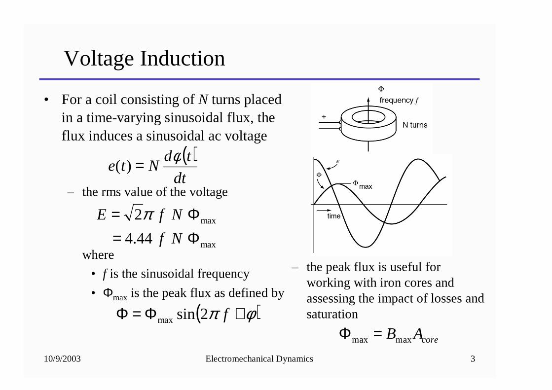
• For a coil consisting of N turns placed in a time-varying sinusoidal flux, the flux induces a sinusoidal ac voltage
– the rms value of the voltage
where
• f is the sinusoidal frequency
• Φmax is the peak flux as defined by
– the peak flux is useful for working with iron cores and assessing the impact of losses and saturation
max
max
44.4
2
Φ=Φ=
Nf
NfE π
( )φπ +Φ=Φ f2sinmax
coreABmaxmax =Φ
( )dt
tdNte
φ=)(
10/9/2003 Electromechanical Dynamics 4
Applied Voltage
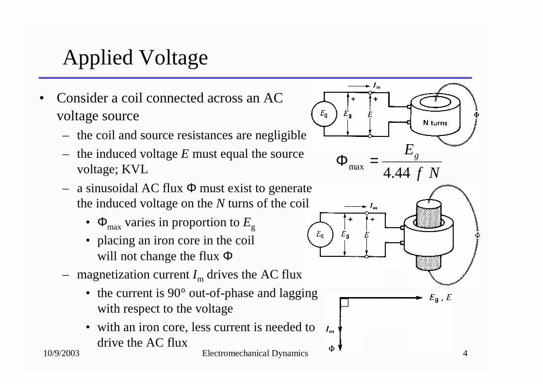
• Consider a coil connected across an AC voltage source– the coil and source resistances are negligible
– the induced voltage E must equal the source voltage; KVL
– a sinusoidal AC flux Φ must exist to generate the induced voltage on the N turns of the coil
• Φmax varies in proportion to Eg
• placing an iron core in the coil will not change the flux Φ
– magnetization current Im drives the AC flux
• the current is 90° out-of-phase and lagging with respect to the voltage
• with an iron core, less current is needed to drive the AC flux
Nf
Eg
44.4max =Φ
10/9/2003 Electromechanical Dynamics 5
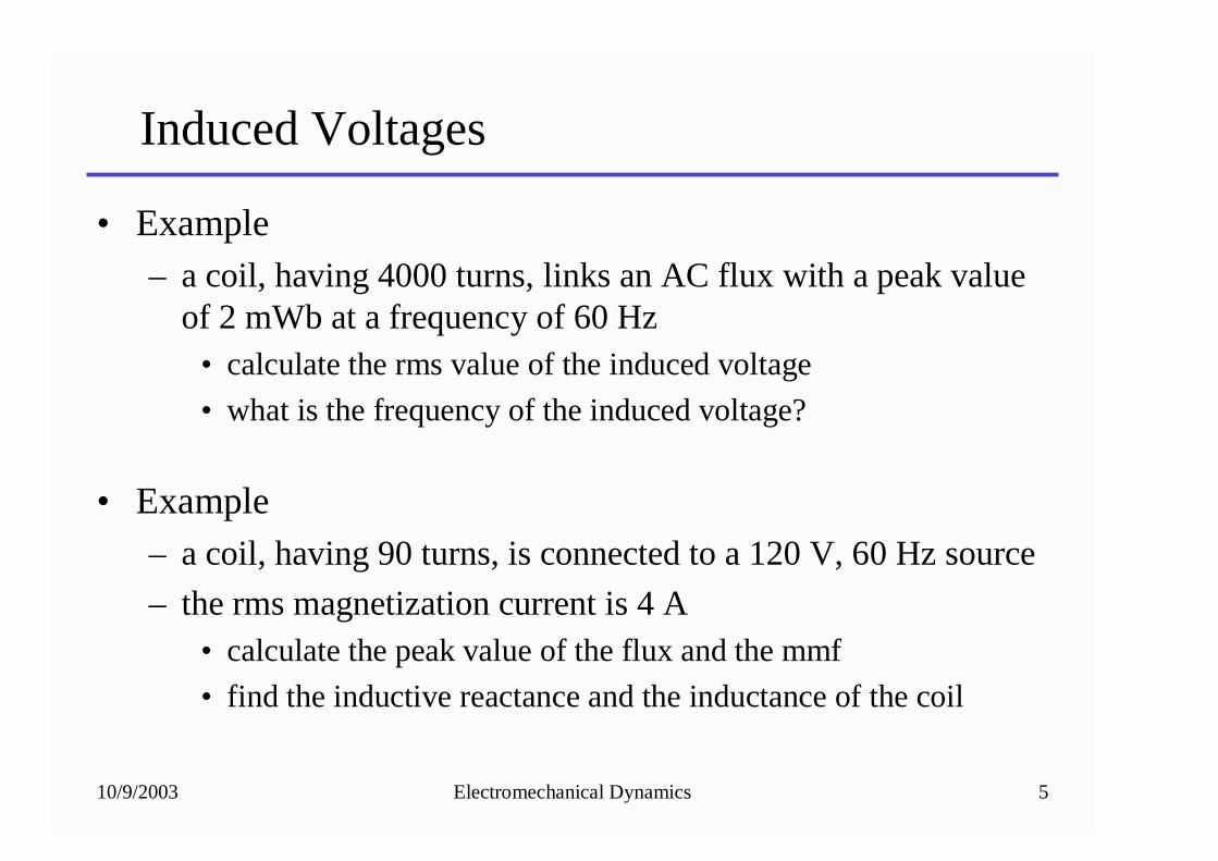
Induced Voltages
• Example– a coil, having 4000 turns, links an AC flux with a peak value
of 2 mWb at a frequency of 60 Hz• calculate the rms value of the induced voltage
• what is the frequency of the induced voltage?
• Example– a coil, having 90 turns, is connected to a 120 V, 60 Hz source
– the rms magnetization current is 4 A• calculate the peak value of the flux and the mmf
• find the inductive reactance and the inductance of the coil
10/9/2003 Electromechanical Dynamics 6
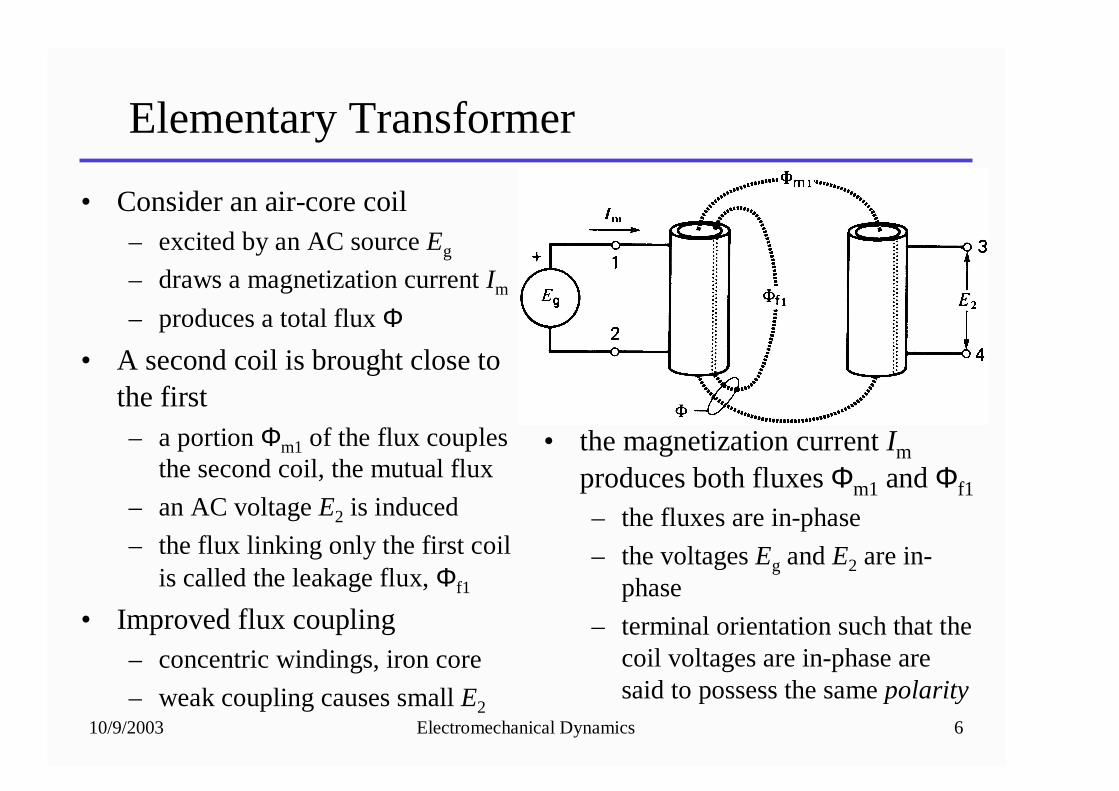
Elementary Transformer
• Consider an air-core coil– excited by an AC source Eg
– draws a magnetization current Im
– produces a total flux Φ• A second coil is brought close to
the first– a portion Φm1 of the flux couples
the second coil, the mutual flux
– an AC voltage E2 is induced
– the flux linking only the first coil is called the leakage flux, Φf1
• Improved flux coupling– concentric windings, iron core
– weak coupling causes small E2
• the magnetization current Im
produces both fluxes Φm1 and Φf1
– the fluxes are in-phase
– the voltages Eg and E2 are in-phase
– terminal orientation such that the coil voltages are in-phase are said to possess the same polarity
10/9/2003 Electromechanical Dynamics 7
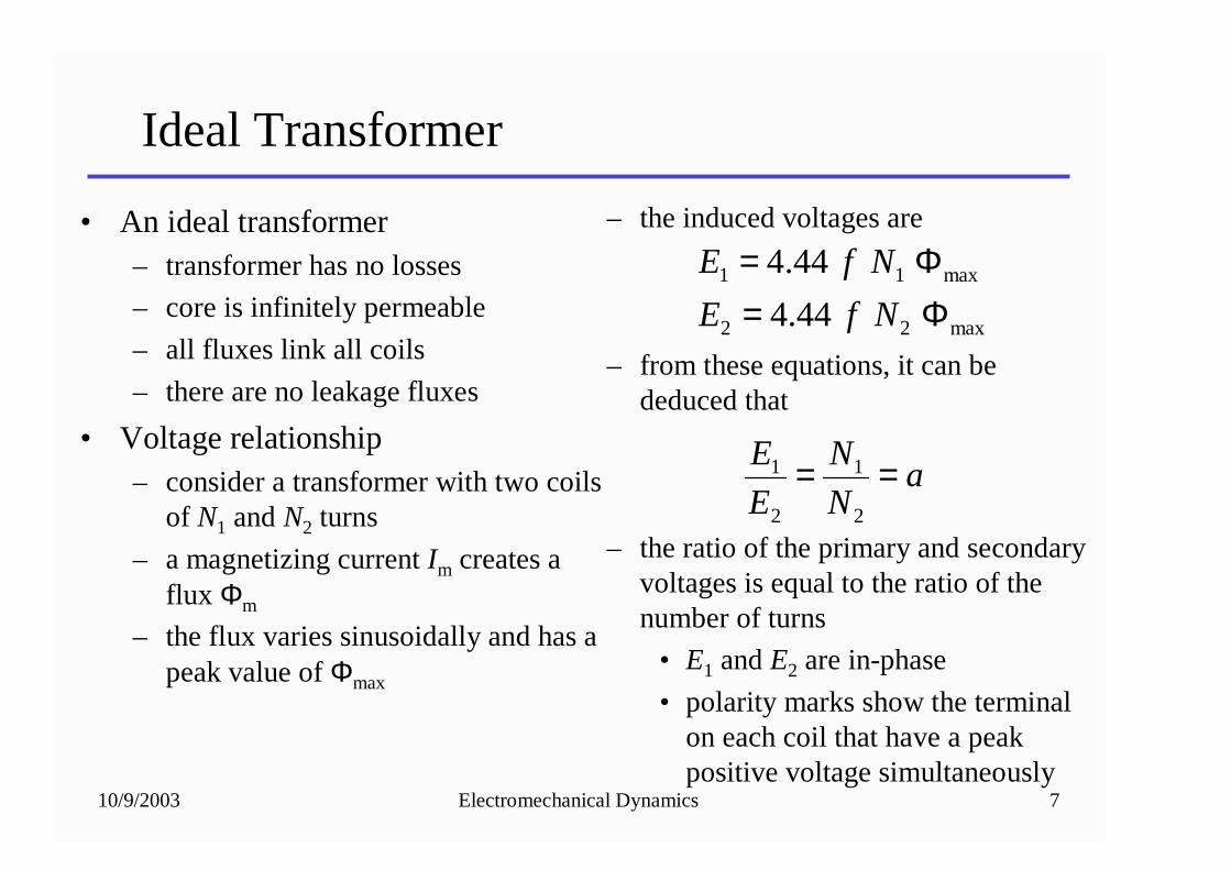
Ideal Transformer
• An ideal transformer– transformer has no losses
– core is infinitely permeable
– all fluxes link all coils
– there are no leakage fluxes
• Voltage relationship– consider a transformer with two coils
of N1 and N2 turns
– a magnetizing current Im creates a flux Φm
– the flux varies sinusoidally and has a peak value of Φmax
– the induced voltages are
– from these equations, it can be deduced that
– the ratio of the primary and secondary voltages is equal to the ratio of the number of turns
• E1 and E2 are in-phase
• polarity marks show the terminal on each coil that have a peak positive voltage simultaneously
max22
max11
44.4
44.4
Φ=Φ=
NfE
NfE
aN
N
E
E ==2
1
2
1
10/9/2003 Electromechanical Dynamics 8
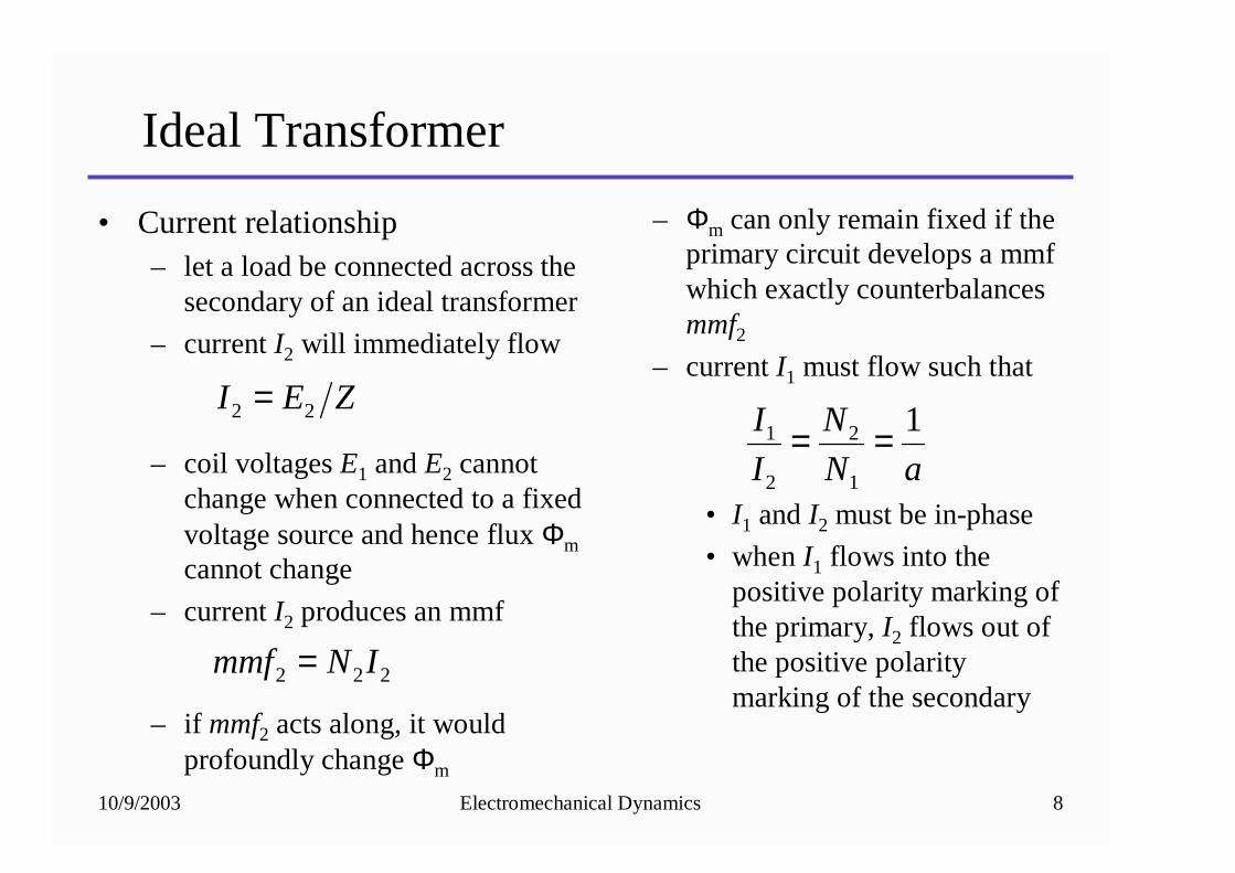
Ideal Transformer
• Current relationship– let a load be connected across the
secondary of an ideal transformer
– current I2 will immediately flow
– coil voltages E1 and E2 cannot change when connected to a fixed voltage source and hence flux Φm
cannot change
– current I2 produces an mmf
– if mmf2 acts along, it would profoundly change Φm
– Φm can only remain fixed if the primary circuit develops a mmf which exactly counterbalances mmf2
– current I1 must flow such that
• I1 and I2 must be in-phase
• when I1 flows into the positive polarity marking of the primary, I2 flows out of the positive polarity marking of the secondary
ZEI 22 =
222 INmmf =
aN
N
I
I 1
1
2
2
1 ==
10/9/2003 Electromechanical Dynamics 9
Ideal Transformer
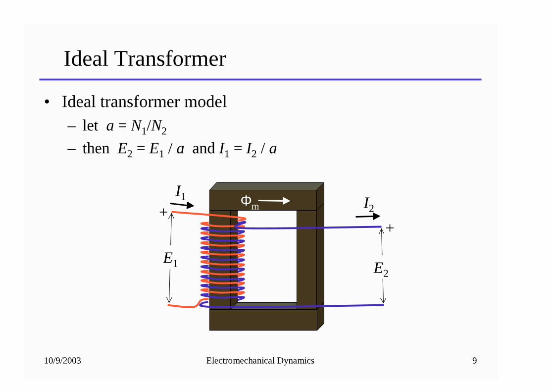
• Ideal transformer model– let a = N1/N2
– then E2 = E1 / a and I1 = I2 / a
E1 E2
++
I1 I2Φm
10/9/2003 Electromechanical Dynamics 10
Ideal Transformer
• Example– a not so ideal transformer has 200 turns in the primary coil
and 10 turns in the secondary coil• the mutual coupling is perfect, but the magnetization current is
1 A
– the primary coil is connected to a 480 V, 60 Hz source
– calculate the secondary rms voltage, peak voltage
• Example– for the transformer above, a load is connected to the
secondary coil that draws 80 A of current at a 0.8 lagging pf
– calculate the primary rms current and draw the phasor diagram
10/9/2003 Electromechanical Dynamics 11
Impedance Ratio
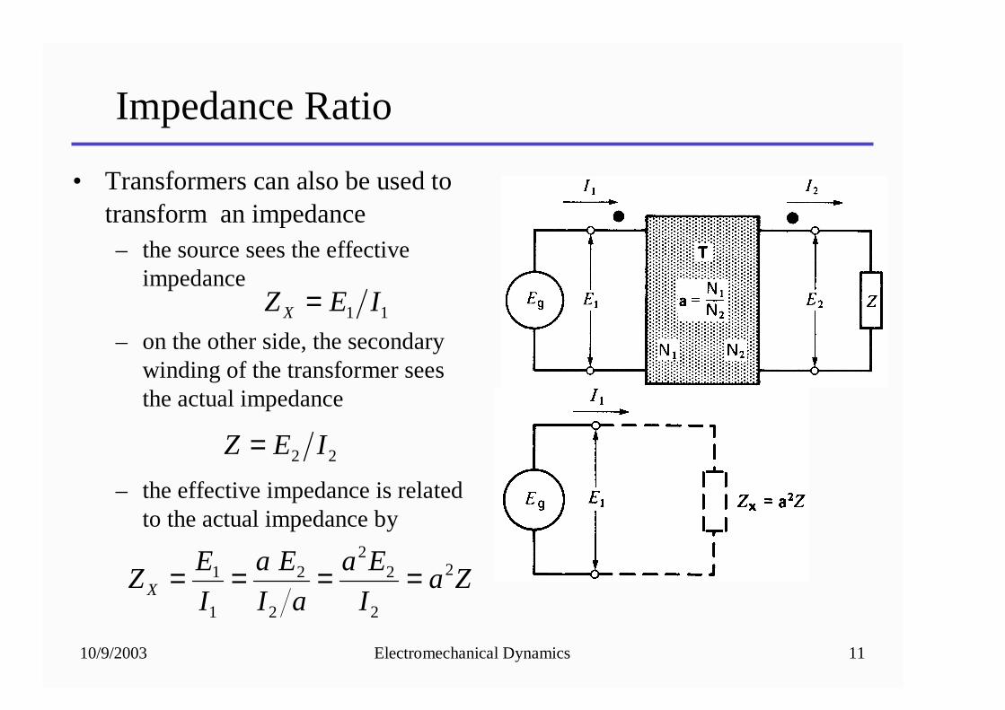
• Transformers can also be used to transform an impedance– the source sees the effective
impedance
– on the other side, the secondary winding of the transformer sees the actual impedance
– the effective impedance is related to the actual impedance by
11 IEZ X =
22 IEZ =
ZaI
Ea
aI
Ea
I
EZ X
2
2
22
2
2
1
1 ====
10/9/2003 Electromechanical Dynamics 12
Shifting Impedances
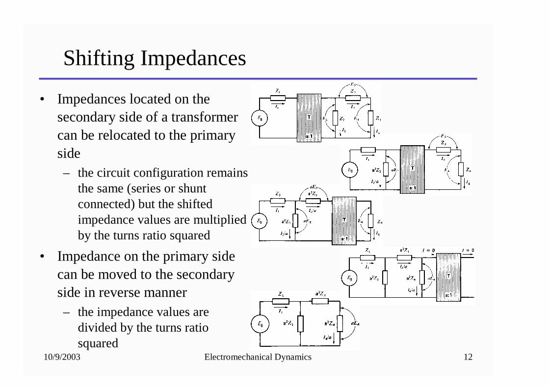
• Impedances located on the secondary side of a transformer can be relocated to the primary side– the circuit configuration remains
the same (series or shunt connected) but the shifted impedance values are multiplied by the turns ratio squared
• Impedance on the primary side can be moved to the secondary side in reverse manner– the impedance values are
divided by the turns ratio squared
10/9/2003 Electromechanical Dynamics 13
Shifting Impedances
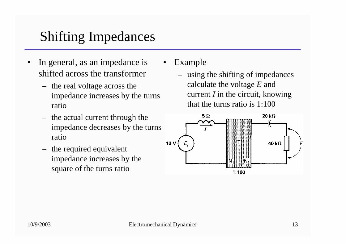
• In general, as an impedance is shifted across the transformer– the real voltage across the
impedance increases by the turns ratio
– the actual current through the impedance decreases by the turns ratio
– the required equivalent impedance increases by the square of the turns ratio
• Example– using the shifting of impedances
calculate the voltage E and current I in the circuit, knowing that the turns ratio is 1:100
10/9/2003 Electromechanical Dynamics 14
Ideal Transformer
• Homework– Problems: 9-4, 9-6, 9-10*
Note: problem 9-10 is a design problem


![Chapter 4: DC Generators - Oakland Universityfrick/EE4220-EM_Dynamics/lecture4.pdfgenerator having a lap winding is given by where ... – Φ= flux per pole [Wb] • Example – the](https://static.fdocuments.net/doc/165x107/5b0605e77f8b9ad1768c3b13/chapter-4-dc-generators-oakland-frickee4220-emdynamicslecture4pdfgenerator.jpg)