
CHAPTER 9, DESIGN STANDARDS - Caltrans - California …€¦ · Web view · 2004-07-06A trench...
117
Local Assistance Procedures Manual Chapter 11 Design Standards CHAPTER 11 DESIGN STANDARDS CONTENTS Section Subject Page Number 11.1 INTRODUCTION ......................................... 11-1 General ..................................... 11-1 Definitions ................................. 11-1 11.2 STATEWIDE DESIGN STANDARDS FOR LOCAL ASSISTANCE PROJECTS 11-3 Roadway and Appurtenances ................... 11-3 Geometric Standards for New and Reconstruction Projects ............... 11-3 Geometric Standards for 3R Projects ... 11-3 Pavement Structural Section ........... 11-6 Signs and Markings .................... 11-6 Traffic Signal Controllers ............ 11-7 Safety ................................ 11-7 Bikeway Standards ..................... 11-7 Pedestrian Facilities ....................... 11-8 Accessibility ......................... 11-8 General Policy ........................ 11-9 Accessible Route ...................... 11-9 Sidewalks and Walks ................... 11-9 Curb Ramps (Wheelchair Ramps) ......... 11-10 Pedestrian Ramps ...................... 11-13 Drainage Inlet Grates ................. 11-14 Driveway Design ....................... 11-15 Width Criteria for Wheelchair Passage . 11-15 Bridges ..................................... 11-15 Definitions ............................ 11-15 Bridge Design Procedures .............. 11-16 Seismic Design ........................ 11-16 Railroad Bridges ...................... 11-17 Bridge Railing ........................ 11-17 Bridges to Remain in Place ............ 11-17 Design of Large Culverts .............. 11-18 Foundation Investigation for Design ... 11-18 Drainage .................................... 11-19 General ............................... 11-19 Definitions ........................... 11-19 February 1, 1998
Transcript of CHAPTER 9, DESIGN STANDARDS - Caltrans - California …€¦ · Web view · 2004-07-06A trench...

Local Assistance Procedures Manual Chapter 11Design Standards
CHAPTER 11 DESIGN STANDARDS
CONTENTS
Section Subject Page Number
11.1 INTRODUCTION ................................................................................................ 11-1General .............................................................................................. 11-1Definitions ......................................................................................... 11-1
11.2 STATEWIDE DESIGN STANDARDS FOR LOCAL ASSISTANCE PROJECTS 11-3Roadway and Appurtenances ........................................................... 11-3
Geometric Standards for New and Reconstruction Projects ................................................................................................. 11-3Geometric Standards for 3R Projects ................................. 11-3Pavement Structural Section ............................................... 11-6Signs and Markings ............................................................. 11-6Traffic Signal Controllers ................................................... 11-7Safety ................................................................................... 11-7Bikeway Standards .............................................................. 11-7
Pedestrian Facilities .......................................................................... 11-8Accessibility ......................................................................... 11-8General Policy ..................................................................... 11-9Accessible Route .................................................................. 11-9Sidewalks and Walks .......................................................... 11-9Curb Ramps (Wheelchair Ramps) ...................................... 11-10Pedestrian Ramps ................................................................ 11-13Drainage Inlet Grates .......................................................... 11-14Driveway Design .................................................................. 11-15Width Criteria for Wheelchair Passage .............................. 11-15
Bridges ............................................................................................... 11-15Definitions ............................................................................. 11-15Bridge Design Procedures ................................................... 11-16Seismic Design ..................................................................... 11-16Railroad Bridges ................................................................. 11-17Bridge Railing ..................................................................... 11-17Bridges to Remain in Place ................................................. 11-17Design of Large Culverts ..................................................... 11-18Foundation Investigation for Design .................................. 11-18
Drainage ............................................................................................ 11-19General ................................................................................ 11-19Definitions ............................................................................ 11-19Hydraulic Design Criteria ................................................... 11-21Flood Plain Encroachments ................................................ 11-22Level of Evaluations ............................................................ 11-23Scour Evaluations ............................................................... 11-23General Design Considerations for Bridges and Culverts ............................................................................... 11-24Documentation .................................................................... 11-24
Standard Plans .................................................................................. 11-24Standard Specifications .................................................................... 11-25
February 1, 1998

Chapter 11 Local Assistance Procedures ManualDesign Standards
CONTENTS CONTINUED
February 1, 1998

Local Assistance Procedures Manual Chapter 11Design Standards
Section Subject Page Number
11.3 LOCALLY DEVELOPED DESIGN STANDARDS ................................................... 11-25Local Geometric Standards .............................................................. 11-25Local Pavement Structural Section .................................................. 11-26
11.4 DESIGN EXCEPTIONS ....................................................................................... 11-26Standards for Which Deviations are Permitted ............................... 11-26Standards for Which Deviations are Not Permitted ........................ 11-27Design Exception Approval Procedures ........................................... 11-27
Local Projects on the State Highway System ...................... 11-27Local Projects not on the State Highway System ............... 11-27Design Exception Fact Sheet ............................................... 11-28Tracking Design Exceptions ................................................ 11-28
11.5 REFERENCES .................................................................................................... 11-28
EXHIBITS
Exhibit Description Page Number
11-A Geometric Design Standards for Local 3R Projects ....................................... 11-31
11-B AASHTO Publications Order Form ............................................................... 11-35
11-C Foundation Investigations For Design ............................................................ 11-37
11-D Preliminary Hydrologic/Hydraulic Review Summary ................................... 11-41
11-E Checklist for Drainage Studies and Reports .................................................. 11-43
11-F Design Exception Fact Sheet ........................................................................... 11-51
11-G Alternative Curb Ramp Shape ....................................................................... 11-53
11-H Built-Up Curb Ramp ...................................................................................... 11-55
11-I Curb Ramp with Vertical Sides ...................................................................... 11-57
11-J Center Island with Slot for Accessibility ........................................................ 11-59
11-K Slots Through Island at Right-Turn Lane ..................................................... 11-61
11-L Center Island with Curb Ramps ..................................................................... 11-63
11-M Straight Ramp Run ......................................................................................... 11-65
11-N Ramp with Intermediate Switch-Back Platform ............................................ 11-67
11-O Ramp with Turning Platform ......................................................................... 11-69
EXHIBITS CONTINUED
February 1, 1998

Chapter 11 Local Assistance Procedures ManualDesign Standards
Exhibit Description Page Number
11-P Transition from Sidewalk to Walk ................................................................. 11-71
11-Q Ramp Used Jointly by Pedestrians and Bicyclists .......................................... 11-73
11-R Sidewalk-Driveway Interface .......................................................................... 11-75
February 1, 1998

Local Assistance Procedures Manual Chapter 11Design Standards
February 1, 1998

Local Assistance Procedures Manual Chapter 11Design Standards
CHAPTER 11 DESIGN STANDARDS
11.1 INTRODUCTION
GENERAL
Project construction plans and specifications must provide for a facility that will adequately meet the existing and probable future traffic in a manner conducive to safety, project economics, durability and economy of maintenance. The design standards used for any project should equal or exceed the minimum standards given in this chapter. Taking into account costs, traffic volumes, traffic and safety benefits, right of way, socio-economic and environmental impacts allows for the use of lower standards only when such use best satisfies the given situation. All exceptions from accepted standards must be justified, documented and retained in the project files.
The purpose of this chapter is to:
Designate “Statewide” design standards, criteria, specifications, procedures, guides, and references that are acceptable for application in the geometric, structural, drainage and pavement design of local federal-aid projects both on and off the National Highway System (NHS).
Describe the procedures to allow the use of “certain locally developed” design standards, including standard specifications and standard plans, as acceptable alternatives to “Statewide” design standards for local federal-aid projects off the NHS.
Outline the “design exception” approval procedures for local federal-aid projects on and off the NHS.
DEFINITIONS
Design Standards -- The standards, specifications, procedures, guides and references listed herein that are acceptable for application in the geometric, structural, pavement and hydraulic design of local federal-aid projects.
Controlling Criteria -- The specific minimum criteria and controls contained in the design standards that are of primary importance for safety. Deviations from these controlling criteria require design exception approval in accordance with Section 11.4 of this chapter.
Design Exception Approval -- A process to justify, approve and document allowable deviations from controlling criteria.
Specifications -- The directions, provisions and requirements contained in the contract documents for a specific construction project. Included are various proposal conditions, contract administration provisions, required construction methods and material specifications.
Standard Specifications -- A published document that contains commonly used specifications developed for use as a reference for construction contract documents.
Page 11-1February 1, 1998
Chapter 11 Local Assistance Procedures ManualDesign Standards
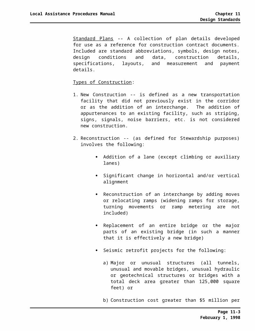
Standard Plans -- A collection of plan details developed for use as a reference for construction contract documents. Included are standard abbreviations, symbols, design notes, design conditions and data, construction details, specifications, layouts, and measurement and payment details.
Types of Construction:
1. New Construction -- is defined as a new transportation facility that did not previously exist in the corridor or as the addition of an interchange. The addition of appurtenances to an existing facility, such as striping, signs, signals, noise barriers, etc. is not considered new construction.
2. Reconstruction -- (as defined for Stewardship purposes) involves the following:
Addition of a lane (except climbing or auxiliary lanes)
Significant change in horizontal and/or vertical alignment
Reconstruction of an interchange by adding moves or relocating ramps (widening ramps for storage, turning movements or ramp metering are not included)
Replacement of an entire bridge or the major parts of an existing bridge (in such a manner that it is effectively a new bridge)
Seismic retrofit projects for the following:
a) Major or unusual structures (all tunnels, unusual and movable bridges, unusual hydraulic or geotechnical structures or bridges with a total deck area greater than 125,000 square feet) or
b) Construction cost greater than $5 million per structure
Major modifications to Traffic Management Centers
3. Preventive maintenance -- Includes, but is not limited to, roadway activities such as joint and shoulder rehabilitation, heater re-mix, seal coats, corrective grinding of PCC pavement, and restoration of drainage systems.
4. 3R Work -- is all other work which does not fall into the above defined categories for new construction, reconstruction or preventive maintenance and typically involves the improvement of highway pavement surfaces through resurfacing, restoration, or rehabilitation. Specifically, 3R Work is defined as the following:
Resurfacing generally consists of placing additional asphalt concrete over a structurally-sound highway or bridge that needs treatment to extend its useful service life.
Restoration means returning a road, structure, or collateral facility to the condition existing after original construction.
Rehabilitation implies providing some betterments, such as upgrading guardrail or widening shoulders.
Page 11-2February 1, 1998

Local Assistance Procedures Manual Chapter 11Design Standards
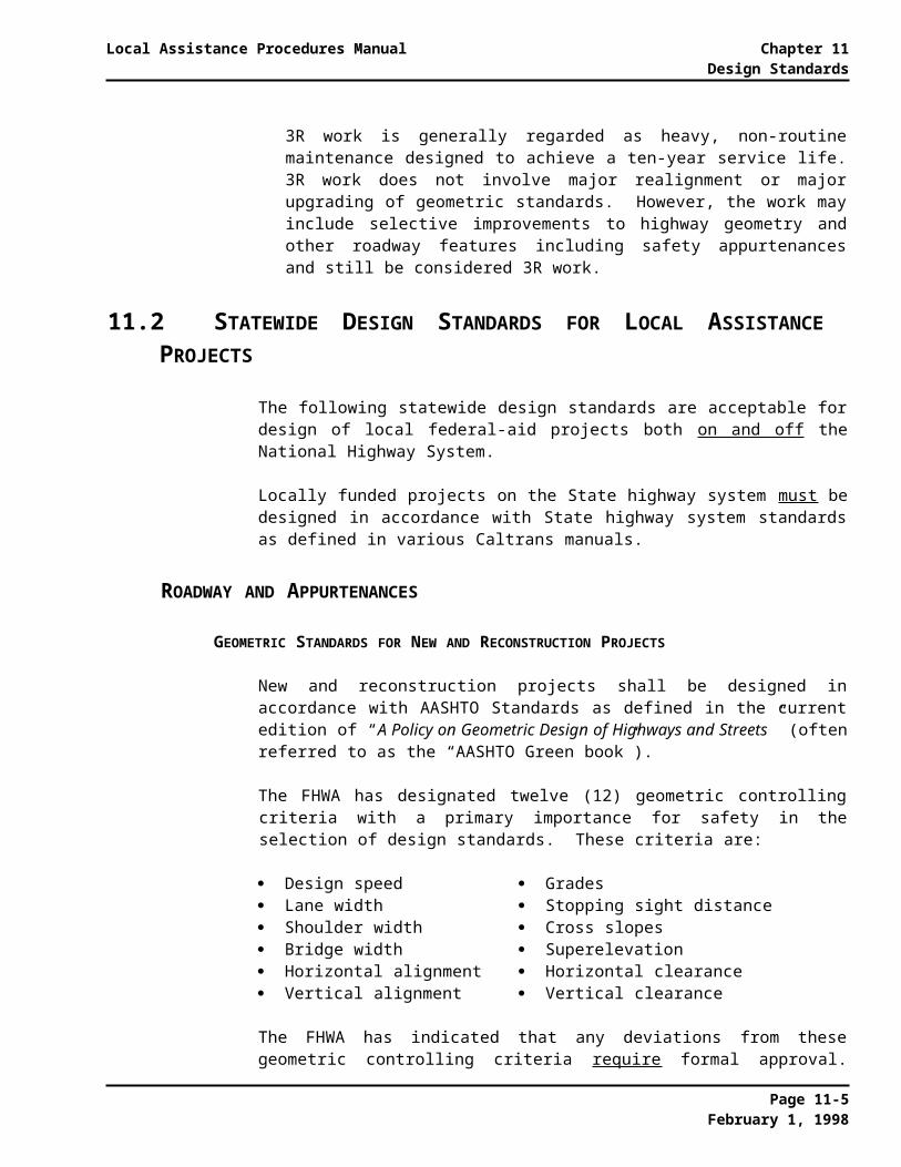
3R work is generally regarded as heavy, non-routine maintenance designed to achieve a ten-year service life. 3R work does not involve major realignment or major upgrading of geometric standards. However, the work may include selective improvements to highway geometry and other roadway features including safety appurtenances and still be considered 3R work.
11.2 STATEWIDE DESIGN STANDARDS FOR LOCAL ASSISTANCE PROJECTS
The following statewide design standards are acceptable for design of local federal-aid projects both on and off the National Highway System.
Locally funded projects on the State highway system must be designed in accordance with State highway system standards as defined in various Caltrans manuals.
ROADWAY AND APPURTENANCES
GEOMETRIC STANDARDS FOR NEW AND RECONSTRUCTION PROJECTS
New and reconstruction projects shall be designed in accordance with AASHTO Standards as defined in the current edition of “A Policy on Geometric Design of Highways and Streets” (often referred to as the “AASHTO Green book”).
The FHWA has designated twelve (12) geometric controlling criteria with a primary importance for safety in the selection of design standards. These criteria are:
Design speed Grades Lane width Stopping sight distance Shoulder width Cross slopes Bridge width Superelevation Horizontal alignment Horizontal clearance Vertical alignment Vertical clearance
The FHWA has indicated that any deviations from these geometric controlling criteria require formal approval. Such deviations from the above criteria require that a local agency obtain design exception approval in accordance with the procedures described in Section 11.4, “Design Exceptions,” in this chapter.
GEOMETRIC STANDARDS FOR 3R PROJECTS
The minimum standards for geometric design of local federal-aid resurfacing, restoration and rehabilitation (3R) projects are shown in Tables 1 through 10 of Exhibit 11-A “Geometric Standards for Local 3R Projects.” Designs using better than minimum standards should be used when feasible, especially in areas of high traffic volume, when design speeds exceed 80 km/h and when significant truck volumes are expected.
The primary purpose of 3R projects is to preserve and extend the service life of existing facilities and enhance highway safety, normally, without major improvements to existing geometric features. However, a reasonable effort should be made to provide uniform geometric standards for a substantial length of roadway. Therefore, the work may include upgrading of geometric features, such as minor roadway
widening, flattening curves, or improving sight distances and still be considered as 3R work.
Page 11-3February 1, 1998
Chapter 11 Local Assistance Procedures ManualDesign Standards
Lane and Shoulder Widths -- Tables 1, 2 and 3 of Exhibit 11-A present the minimum 3R standards for widths of traffic lanes and shoulders on roadways classified as arterials, collectors and local roads and streets.
Table 4 presents the minimum 3R standards for traffic, turning, parking and bicycle lanes for urban streets and roads with curb and gutter.
Wide lanes and shoulders give motorists: 1) increased opportunity for safe recovery when their vehicles run off the road and 2) increased lateral separation between overtaking and meeting vehicles. Added safety benefits include improved site distance at critical horizontal curves, reduced interruption from emergency stopping and road maintenance activities, less wear at the lane edge, and better roadway surface drainage.
Traffic volumes influence the cost-effectiveness of lane and shoulder widening because the number of accidents eliminated by lane and shoulder widening increases almost in proportion to ADT, whereas the costs are not affected significantly by ADT. Lane and shoulder widening can also produce time savings for highway users, which can be an important consideration for highways with ADT greater than 2,000 vehicles per day.
Bridge Widths -- The minimum bridge width values for 3R projects involving bridges to remain in place on arterial, collectors and local streets and roads are shown in Tables 5, 6 and 7 of Exhibit 11-A. 3R projects on such bridges involve mainly roadway resurfacing and improvements to railings. More significant work, such as structural strengthening or deck replacement is classified as reconstruction and must meet AASHTO standards.
The relationship between bridge width and the width of approach lanes influences bridge safety; roadway constriction at narrow bridges reduces the opportunity for safe recovery by out-of-control vehicles and may result in collisions with bridge abutments.
Thus, the safety cost-effectiveness of bridge width improvements depends upon the usable width of the bridge, the width of the approach lanes, traffic volumes and the length of bridge.
Horizontal Clearance -- Sideslope and clear zone improvements on 3R projects should meet the following criteria:
a) Flatten sideslopes of 3:1 or steeper at locations where run-off-the-road accidents are likely to occur, such as on the outside of sharp horizontal curves.
b) Whenever possible, sideslopes should not be steepened when widening lanes and shoulders.
c) Remove, relocate or shield isolated roadside obstacles.
Roadside characteristics are important in determining the overall level of safety provided by a highway. Accident rates are lower and accidents are less severe on highways with gentle sideslopes and few obstacles near the roadway.
Page 11-4February 1, 1998
Local Assistance Procedures Manual Chapter 11Design Standards
Removing isolated trees and relocating utility poles can be more safety cost-effective than widening lanes or flattening horizontal curves.
Horizontal Alignment -- Values for stopping sight distance and horizontal curves for 3R projects are shown in Tables 8, 9 and 10 of Exhibit 11-A.
Safety often can be improved at horizontal curves without costly reconstruction. Local agencies should evaluate other safety measures when reconstruction is unwarranted. Such measures might include widening lanes, widen and paving shoulders, flattening steep sideslopes, removing or relocating roadside obstacles, and installing traffic control devices, raised pavement markings and reflective guideposts.
Accidents are more likely to occur on horizontal curves than on straight segments of roadway because increased demands are placed on the driver and vehicle and centrifugal force tends to cause a vehicle to run off the road. The safety effect of an individual curve is influenced not only by the curve’s geometric characteristics, but also by the geometry of adjacent highway segments. Safety considerations are important especially when a curve is unexpected, such as when it follows a long straight approach or when it is hidden from view by a hill crest.
Depending on site conditions, improvements to curves can be an inexpensive and effective means of reducing the severity and frequency of accidents.
Vertical Alignment -- Values for superelevation, grades and stopping sight distances are included in Tables 8, 9 and 10 of Exhibit 11-A. For sustained downgrades, consideration should be given to increasing the minimum stopping sight distances shown in the above tables.
The Transportation Research Board recommends that local agencies evaluate the option of reconstructing hill crests when:
a) The hill crest hides from view such conditions as: intersections, sharp horizontal curves or narrow bridges.
b) The average daily traffic is greater than 1,500 vehicles per day.
c) The design speed of the hill crest (based upon the minimum sight distance provided) is more than 30 kph below the 85th percentile speeds of vehicles on the crests.
Whether or not the reconstruction of a hill crest is necessary, designers should examine the nature or potential hazards hidden by a hill crest and consider other options such as removing potential hazards or providing warning signs.
Sight obstructions at hill crests can be corrected only by changing the vertical alignment to lengthen the existing vertical crest curve.
Generally, to be safety cost-effective, vertical alignment improvements must correct a substantial sight distance restriction that affects a driver’s ability to anticipate difficult situations, such as turning vehicles, sharp curves, or other conditions that demand specific driver responses.
Page 11-5February 1, 1998

Chapter 11 Local Assistance Procedures ManualDesign Standards
Pavement Crown and Edge Drops -- Local agencies performing resurfacing projects should consider constructing pavement overlays with pavement crowns that match AASHTO standards for new construction.
Resurfacing projects offer opportunities to improve surface drainage and vehicle control in wet weather by correcting deficient cross slopes at little or no additional cost.
Pavement edge drops result either from resurfacing activity unaccompanied by desirable shoulder improvement or from wear or erosion of weak shoulder material. Resurfacing can increase the likelihood that edge drops will develop later and require repeated maintenance to correct.
Consideration should be given to paving shoulders selectively to improve all-weather use and prevent edge drop problems from occurring on either the inside of outside of a short radius curve.
PAVEMENT STRUCTURAL SECTION
The design of a pavement structural section is not an exact science. The design guidelines and standards referenced herein are based on a wide range of factors. The final pavement design must be based on a thorough investigation of specific project conditions including materials, environmental conditions, projected traffic, life-cycle economics and the performance of other like pavement structural sections under similar conditions in the same area.
The structural section of the roadbed should conform to:
Section 600 of the Caltrans Highway Design Manual,
Caltrans Flexible Pavement Structural Section Design Manual, or
Flexible Pavement Structural Section Design Guide for California Cities and Counties, published by Caltrans in cooperation with County Engineers Association of California and the League of California Cities.
SIGNS AND MARKINGS
Informational, regulatory and warning signs, curb and pavement or other markings and traffic signals installed or placed on any project constructed with federal funds shall conform to the Caltrans Traffic Manual.
The Federal Highway Administration (FHWA) has indicated that school crosswalks and other school markings should conform to the Manual on Uniform Traffic Control Devices (MUTCD) in the interest of national uniformity. However, the FHWA does not prohibit the use of yellow school crosswalk markings as required by California law. The FHWA will participate in the cost of the yellow school crosswalk markings. The MUTCD is available through the Government Printing Office in San Francisco, Phone No. (415) 512-2270.
Deviations from the “Mandatory Standards” for signs and markings as defined and shown in the Caltrans Traffic Manual are not permitted.
Page 11-6February 1, 1998

Local Assistance Procedures Manual Chapter 11Design Standards
TRAFFIC SIGNAL CONTROLLERS
Assembly Bill 3418 (1995) which amended Section 21401 of the California Vehicle Code requires “any traffic signal controller that is newly installed or upgraded by the Department of Transportation or a local authority after January 1, 1996, shall be of a standard traffic signal communication protocol capable of two-way communications.” Communication standards for traffic signal controllers are available from the National Transportation Communications for ITS Protocol. This information may be accessed through the Internet at http://www.ntcip.org/.
SAFETY
The following publications have also been developed to aid the designer in improving highway safety:
Caltrans Traffic Manual (deviations from mandatory standards for signs and markings are not permitted)
Designing Safer Roads, Special Report 214, Transportation Research Board Roadside Design Guide, 1995 (available through AASHTO)
These publications are primarily informational or guidance in nature and serve to assist local agencies in knowing the information valuable to attaining good designs. All designers should be familiar with these documents. Although the principles contained are written primarily for high-speed highway facilities, consideration should be given to their application on other types of projects regardless of traffic volumes and design speed. Project-by-project deviations from the criteria in these publications do not require handling in accordance with design exception approval procedures cited in Section 11.4 of this chapter. However, any deviations should be justified and documented in the project files.
Evaluating accident records is an integral step in developing highway projects and often reveals problems requiring special attention and corrective action. Accident records are available from the Statewide Integrated Traffic Records System (SWITRS) for analysis. Relative accident rates can influence the priorities of projects and ensure that project objectives and the scope of design are related to accident causes. In addition, it may be necessary to use a cost/benefit study and an investigation of accident experience to determine if the correction of an identified safety problem is cost effective. Significant safety problems, such as narrow bridges or culverts, railroad crossings or fixed objects which are not cost effective to correct, must be provided with suitable warning and traffic control devices. For example, no bridges may be left in place which have a width narrower than the surfaced approach roadway unless suitable signing, marking and parapet protection are provided.
On many local agency projects, right of way considerations may limit the extent to which side slopes may be flattened and roadside clearances obtained. In such situations it is expected that the desired smooth and obstacle-free roadside will be obtained to the extent feasible.
BIKEWAY STANDARDS
The standards for bikeway projects shall conform to Chapter 1000 of the Caltrans Highway Design Manual. Deviations from the “mandatory” bikeway standards stated therein require approval in accordance with the design exception approval procedures described in Section 11.4 of this chapter.
Page 11-7February 1, 1998

Chapter 11 Local Assistance Procedures ManualDesign Standards
PEDESTRIAN FACILITIES
ACCESSIBILITY
Title II of the federal law known as the Americans with Disabilities Act (ADA) of 1990 prohibits discrimination on the basis of disability by public entities. This means that a public entity may not deny the benefits of its programs, activities and services to individuals with disabilities because its facilities are inaccessible. A public entity’s services, programs, or activities, when viewed in their entirety, must be readily accessible to and usable by individuals with disabilities. This standard, known as “program accessibility,” applies to all existing facilities of a public entity. Public entities, however, are not required to make each of their existing facilities accessible, as long as persons with disabilities have “equal access” to the goods and services provided to persons without disabilities.
Public entities may achieve program accessibility by a number of methods. In many situations, providing access to facilities through structural methods, such as alteration of existing facilities and acquisition or construction of additional facilities, may be the most efficient and “equal” method of providing program accessibility.
Where structural modifications are required to achieve program accessibility, a public entity (city, county, or State of California) with 50 or more employees is required to develop a transition plan setting forth the steps necessary to complete such modifications. A public entity shall also provide an opportunity to interested persons, including individuals with disabilities or organizations representing the same, to participate in the development of the transition plan by submitting comments. A copy of the transition plan must be made available for public inspection for a period of three years.
If a public entity has responsibility or authority over streets, roads or walkways, its transition plan shall include a schedule for providing curb ramps or other sloped areas where pedestrian walkways cross curbs, giving priority to walkways serving local government offices and facilities, transportation and places of public accommodation, followed by walkways serving other areas.
The State of California has also adopted regulations specifying that all buildings, structures, sidewalks, curbs and related facilities constructed in California by the use of State, county or municipal funds, or the funds of any political subdivision of the State, shall be accessible to and usable by persons with disabilities. The Division of the State Architect (DSA) is given responsibility for developing regulations and standards to ensure full accessibility. These regulations and standards are to prescribe no lesser a standard of accessibility or usability than provided by the Accessibility Guidelines prepared by the Federal Access Board (see below) to implement the ADA (ref: Government Code Section 4450).
Based on both the federal and State laws and regulations, all newly-constructed facilities must allow full accessibility. When existing facilities are being reconstructed or modified, the contract must also include work to make these facilities fully accessible. "Title II-6.6000" of the Department of Justice's "Technical Assistance Manual" further clarifies this by stating: "When streets, roads, or highways are newly built or altered, they must have ramps or sloped areas wherever there are curbs or other barriers to entry from a sidewalk or path. Likewise, when new sidewalks or paths are built or are altered, they must contain curb ramps or sloped areas wherever they intersect with streets, roads, or highways. Resurfacing beyond normal maintenance is an alteration. Merely filling potholes is considered to be normal maintenance."
Page 11-8March 15, 2001 LPP 01-04
Local Assistance Procedures Manual Chapter 11Design Standards
State and local governments, regardless of whether they receive federal funds, are required to comply with the Federal ADA Accessibility Guidelines (ADAAG), Title 24, or Local Code, whichever provides the greatest access. Private-funded improvements are required to comply with the Federal ADA Accessibility Guidelines (ADAAG) and with Title 24, whichever code offers the greatest access or protections to individuals with disabilities.
Page 11-8aLPP 01-04 March 15, 2001

Chapter 11 Local Assistance Procedures ManualDesign Standards
Page 11-8bMarch 15, 2001 LPP 01-04

Local Assistance Procedures Manual Chapter 11Design Standards
Most State statutes addressing accessibility are included in Part 2, Title 24, California Code of Regulations (later referred to as “Title 24”). Other statutes are incorporated in various other State Codes. These various statutes cover the broad subject of accessibility, with little specific reference to transportation-related facilities. Specific sections of the State Building Code, which is included in Title 24, addresses Site Accessibility. These sections are interpreted to apply to transportation-related facilities, such as curb ramps and parking.
In November 1994 the DSA published the California Accessibility Reference Manual which includes all of the above-referenced Code sections. However, this publication is currently out of print, and the DSA has no plans to print additional copies.
The information presented below has been derived from discussions and correspondence with federal and State officials. Much of the information is interpretive or suggestive and was developed because the federal and State regulations do not specifically address various situations typically faced in providing accessibility in conjunction with transportation-related facilities.
GENERAL POLICY
State and local governments are required to comply with the federal regulations contained within the Uniform Federal Accessibility Standards (UFAS) when federal funds are used to construct improvements. However, appropriate State standards must also be considered. If there is a conflict between the federal and State standards and regulations, the higher standard must be used.
ACCESSIBLE ROUTE
An Accessible Route is defined in the UFAS as being “a continuous unobstructed path connecting all accessible elements and spaces in a building or facility...Exterior accessible routes may include parking access aisles, curb ramps, walks, ramps, and lifts.” It is the latter part of this definition which is of most concern regarding facilities commonly dealt with by transportation agencies.
In the State regulations Title 24, Accessible Route of Travel is defined as a continuous unobstructed path connecting all accessible elements and spaces in an accessible building or facility that can be negotiated by a person with a severe disability using a wheelchair and that is also safe for and usable by persons with other disabilities, and that also is consistent with the definition of “path of travel.”
Title 24 defines a Path of Travel as a passage that may consist of walks and sidewalks, curb ramps and pedestrian ramps, lobbies and corridors, elevators, other improved areas, or a necessary combination thereof, that provides free and unobstructed access to and egress from a particular area or location for pedestrians and/or wheelchair users.
Taken together, these definitions mean that any area that is intended for use by pedestrians must be made fully accessible.
SIDEWALKS AND WALKS
Sidewalks and walks serve basically the same purpose. However, sidewalks are not defined in the UFAS. A walk is defined in the UFAS as being an “exterior pathway with a prepared surface intended for pedestrian use, including general pedestrian areas such as plazas and courts.” Of particular note is that the definition does not require the walk to be paved with any specific material, such as asphalt or concrete. Under Minimum Requirements, ground surfaces along accessible routes, including walks and curb ramps, are specified to comply with the requirement that they be “stable, firm, slip-resistant.”
Page 11-9February 1, 1998

Chapter 11 Local Assistance Procedures ManualDesign Standards
In the State regulations the two facilities are defined differently:
Sidewalk - is a surfaced pedestrian way contiguous to a street used by the public. (Title 24)
Walk - is a surfaced pedestrian way not located contiguous to a street used by the public. (Title 24)
From these definitions the question is often raised as to what constitutes “a surfaced pedestrian way.” This phrase is not properly defined in either the federal or State regulations. However, the UFAS does provide the Minimum Requirements noted above. From the State regulations another definition is applicable.
Ground and Floor Surfaces - along accessible routes including floors, walks, ramps, stairs and curb ramps, shall be stable, firm, and slip-resistant. (Title 24)
Based on these various requirements, an accessible route does not have to be paved with material such as concrete or asphalt.
CURB RAMPS (WHEELCHAIR RAMPS)
Curb ramps, as part of the roadway facility, are probably the most visible facility constructed to provide full accessibility. A common term used for these ramps is “wheelchair ramps.” Even though they provide great benefit to wheelchair users, they are also very useful to pedestrians with walking disabilities. This would include those using walkers or crutches, and those with balance problems. Also, visually-impaired pedestrians benefit from having abrupt edges and drop-offs eliminated.
The Caltrans Standard Plan A88 provides details for the design and construction of curb ramps in various configurations, or “Cases.” These details comply with UFAS requirements and have been approved by the DSA. One minor variation of the basic configuration of the curb ramps is allowable. This is shown in Exhibit 11-G.
Questions are frequently asked relative to various details which may not be addressed on Standard Plan A88. Some of these questions are addressed in the following:
One question often raised is why there is no “lip” shown at the bottom of the curb ramp. This detail was included on previous versions of Standard Plan A88. However, the presence of the lip was a conflict between federal and State standards; one called for it and the other did not. The conflict centered around whether the lip provided a discernible warning to visually-impaired pedestrians, and whether it presented an unnecessary obstacle to wheelchair users. Prior to developing the May 29, 1996 version (and later versions) Standard Plan A88 this conflict was resolved, and the lip has been eliminated.
Prior to May 29, 1996 another detail shown on the Standard Plans was a built-up curb ramp which could be constructed by placing (usually) asphalt from the top of the curb across the gutter and down into the roadway (see Exhibit 11-H). This option has been eliminated, as all curb ramps are to be constructed clear of the traveled way. An example of when this type of built-up curb ramp may be constructed is when it leads into a roadway which has been converted to pedestrian-only use and there is no possibility of conflicts with vehicular traffic.
Grooves
The grooves shown on Standard Plan A88 around the top of the curb ramps are intended
Page 11-10February 1, 1998

Local Assistance Procedures Manual Chapter 11Design Standards
to provide a visual warning to able-bodied or visually-impaired pedestrians, but, contrary to some people’s belief, are not intended to be a warning to blind pedestrians. The grooves cannot be detected by a blind person using a cane.
The grooved warning is provided to sighted pedestrians to indicate there is a change taking place. In this case it is the change in slope or level of the sidewalk. Since these grooves are not intended as a warning to blind pedestrians, other visual warnings may be substituted for the grooves when it is necessary or desirable to do so. For instance, in geographical areas which experience periodic wet, freezing weather the freeze/thaw cycles may damage the grooves causing an ongoing maintenance chore and render them useless. An alternative in this case would be to use a painted stripe; with the realization that one maintenance chore is being traded for another. Another example of when a painted stripe could be used is when the walkway is made of wood.
Other design options can accomplish the intent of providing a visual warning. A delineation stripe could be created by placing pavers of a contrasting color. In areas where brick or other pavers are used for constructing the sidewalk, a curb ramp of PCC alone provides a contrast and probably would not need a stripe around its border.
Utility Facilities
Utility facilities are often asked about. The questions center around whether those facilities may remain within the area of a curb ramp. This is really a two-part question. One part deals with the flared side wings, or sloped transition areas, of the curb ramp. The other part deals with the flat part of the curb ramp which is the path of travel. This question has been addressed by both federal and State authorities.
The primary function of the flared sides, or wings, of a curb ramp is to alert visually-impaired pedestrians to the presence of the curb ramp, by the change in slope of the sidewalk, and to allow safe travel transversely across the ramp. In some cases it is not necessary to construct these flared sides. This would be where the curb ramp is protected by handrails or guardrails, or where a planting area or other non-walking surface is adjacent to the curb ramp. An example of this condition is shown in Exhibit 11-I. Traffic signal and utility poles and other above-ground obstructions may remain within the flared sides, for this is comparable to them being located in the flat areas of a sidewalk.
The important consideration is for the flat portion of the curb ramp (the path of travel) to be clear of obstructions, such as posts and poles. This clear area is necessary to allow persons who are not fully ambulatory to be able to move from one level to another. This means persons in wheelchairs, those using walkers, those with other walking aids, etc. Utility boxes, vaults, etc. within the flat area of a curb ramp would not be considered an obstacle for these persons if they are flush with the curb ramp surface and have a skid-resistant surface.
Note 12 on Standard Plan A88 addresses the relocation or adjustment to grade of utility boxes, vaults, etc. Here it should be kept in mind that the Standard Plans are intended primarily to convey information to contractors. Thus, the explanations included in the paragraphs immediately above are not shown on the standard plans, as these explanations are intended for use by designers in determining what needs to be specified for the contractor to do.
Detectable Warning Surfaces
Federal standards do not require detectable warning surfaces to be applied to curb ramps.
Page 11-11February 1, 1998

Chapter 11 Local Assistance Procedures ManualDesign Standards
The Caltrans Standard Plan A88 does provide details regarding the use of detectable warning surfaces.
Detectable warning surfaces are also technically referred to as tactile warning surfaces. In common usage, the term “truncated domes” is also used. Actually, “truncated domes” is a description of the raised shapes which make up the detectable warning surfaces.
One detail regarding detectable warning surfaces is changed on the May 29, 1996 version (and later versions) of Standard Plan A88. This has to do with the orientation of the truncated domes. Prior versions of the Plan showed these domes in a pattern oriented 45 degrees to the direction of travel. This pattern has been changed to show the truncated domes oriented with the direction of travel. This change was made to allow easier “tracking” for wheelchairs.
Standard Plan A88 provides information relative to the use of truncated domes on curb ramps, including the requirement that detectable warning surfaces should be installed when curb ramp slopes are flatter than 6.67%. This criteria is based on the needs of visually impaired pedestrians. If a curb ramp slope is greater than 6.67%, a visually impaired pedestrian leaving a safe area (such as a sidewalk) can detect the slope, and would know they are approaching an area of possible conflict. However, if the slope is less than 6.67%, they may not be able to detect the slope. In this case, the detectable warning surface is used to alert them to the possibility of conflict. As they leave an area of conflict, the slope greater than 6.67% or the detectable warning surface assures them they are once again approaching an area of safety.
Curb Cuts Through Islands
Two terms often used interchangeably are “curb ramps” and “curb cuts.” However, as used in this discussion, there is a distinct difference.
In this discussion, curb cuts refer to “slots” which would be cut through a curb or through an island. Having curb cuts constructed through an island would preclude the necessity of constructing curb ramps on each side of that island. Islands most frequently impacted would be those in the middle of a street or between through lanes and a right-turn lane. These conditions are illustrated in Exhibits 11-J and 11-K. The UFAS specifies details regarding curb cuts, but the State regulations do not.
When islands are wide enough, curb ramps and a landing may be used instead of a curb cut. If this design is used, the landing must be at least 1.22 m long (in the direction of travel). This option is shown in Exhibit 11-L. In this case, the landing is to provide a safe refuge area in the event the entire width of the street cannot be crossed in one signal cycle, or if there is no signal to provide crossing protection.
When either of the options above are used, consideration should be given to the State regulations regarding providing detectable warning surfaces (truncated domes) if certain conditions are present. In the discussion above, explanation is given regarding curb ramps with a slope greater than or less than 6.67%. The same information should be used as basic guidance for providing detectable warning surfaces on curb cuts. This is discussed in the following paragraph.
Curb cuts, being just slots through an island, would most-often have only a minimal slope. Thus, they would probably not meet the 6.67% slope criteria used for determining whether to place detectable warning surfaces on curb ramps. In these cases detectable warning surfaces should be installed at the beginning and at the end of the curb cut. This
Page 11-12February 1, 1998

Local Assistance Procedures Manual Chapter 11Design Standards
would provide warning to visually-impaired pedestrians that they were entering and leaving a safe refuge area (the island). There should also be an area provided with a minimum length of 1.22 m (in the direction of travel) between the detectable warning surfaces. This would provide two benefits. For the visually-impaired pedestrian, it would provide a definitive break between the surfaces to alert them of a distinct change. Second, for wheelchair users it would provide an unobstructed area for them to have refuge. With the requirement that detectable warning surfaces be 600 mm minimum length (in the direction of travel) this means that unless an island is at least 2.44 m (in the direction of travel for a pedestrian), the detectable warning surfaces should not be placed.
PEDESTRIAN RAMPS
The UFAS specifies that any part of an accessible route with a slope greater than 1:20 (5%) shall be considered a ramp, and the least possible slope shall be used for any ramp. The maximum slope of a ramp in new construction is specified to be 1:12 (8.33%). These same criteria are specified in the State Title 24. Both regulations specify the cross slope of ramps to be 1:50 (2%).
There is a difference in width requirements between the federal and State regulations. The UFAS requires a ramp to have a minimum clear width of 915 mm (36 in). The State Title 24 specifies a width of 60 inches if the ramp serves a primary entrance to buildings having an occupant load of 300 or more, and 36 inches when the occupant load is 50 or less. The State requirement for the width of all other ramps is 48 inches.
Both UFAS and the State Title 24 specify the need for intermediate landings within the length of ramps, with the location of landings dependent upon the rise and horizontal length of the ramp. These standards differ and are presented in Table 11-1 for information.
TABLE 11-1Federal UFAS Standards
Maximum Rise Maximum Horizontal Projection
Slope mm in m ft
1:12 to < 1:16 760 30 9 30
1:16 to < 1:20 760 30 12 40
Page 11-13February 1, 1998

Chapter 11 Local Assistance Procedures ManualDesign Standards
State Title 24 Standards
Maximum Rise Maximum Horizontal Projection
Slope mm in m ft
1:12 760 30 9 30
1:15 760 30 11.5 37.5
1:16 760 30 12 40
1:20 760 30 15 50
Note: Title 24 specifies only English height and length criteria. Metric values shown here are rounded.
There are also differences regarding the criteria for size of landings on ramps. These differences are illustrated in Exhibits 11-M, 11-N, and 11-O. These exhibits and others herein do not show any handrails, curbs or other protection which may be required.
There is often the question of when does a sidewalk become a walk, or when does a walk become a ramp, or how are landings handled on these facilities. Resolution of these issues is illustrated in the following example:
Exhibit 11-P shows a facility jointly used by pedestrians and bicyclists which transitions from being a sidewalk to a walk, and which must have ramps constructed along the walk area. Within the length where the facility is contiguous to the roadway it is considered a sidewalk. In this sidewalk area, the grade of the facility is controlled by that of the roadway. Where it diverges from the roadway it is considered a walk. In this area it becomes a ramp as it descends away from the roadway, and requirements for maximum grade and placement of landings must be met. However, since the facility is also used by bicyclists it would not be desirable to place landings within the ramp. The need for landings may be met by constructing them adjacent to the ramp proper. This concept is shown in Exhibit 11-Q.
DRAINAGE INLET GRATES
The placement of drainage inlet grates relative to curb ramps is an important safety consideration faced by designers. Ideally, drainage inlet grates should not be placed in the pedestrian path of travel. Design for new construction should take this into account. But situations arise (i.e. intersection modification) where these grates must be placed within the path of travel. In such cases, a grate opening of no more than 12.5 mm in the direction of travel is allowed. A trench drain system with said grate can meet this requirement. If Caltrans standards are used, currently only Standard Plan D98B (slotted corrugated steel pipe with heel guard) meets this requirement. Modifying another Caltrans standard grate to meet this requirement is not allowed for projects on the State highway system.
If using Caltrans Standard Plan D98B within the path of travel, the pipe should be connected to an inlet that is offset from the path of travel. With this system, a clogging factor of 50% should be assumed, and it should be noted that the interception of runoff would be less than that calculated using the design indicated in Hydraulic Engineering Circular (HEC) - 22.
Page 11-14February 1, 1998

Local Assistance Procedures Manual Chapter 11Design Standards
Regardless of the standard, if a drainage inlet grate is designed within the path of travel, the following shall be considered:
Adjacent inlets should be placed and configured to limit bypass and reduce the amount of runoff reaching the path of travel.
The grate opening restriction of 12.5 mm could result in clogging, and therefore more maintenance.
DRIVEWAY DESIGN
The design of driveways needs special attention to preclude them being constructed in a manner which presents maneuvering difficulties for pedestrians with disabilities. The driveway grade, in the direction of vehicular travel, is the cross slope for a sidewalk used by pedestrians who traverse the driveway. The UFAS specifies a maximum cross slope for an accessible route to be 1:50 (i.e., 2%). This standard is also reflected in State regulations. In order to maintain this maximum cross slope for the sidewalk, the driveway profile grade may have to be a non-continuous grade, and may have to extend some distance beyond the back of sidewalk.
The Caltrans Standard Plan A87 shows one possible design which complies with the maximum cross slope criterion. This concept, with a little variation, is also shown in Exhibit 11-R.
WIDTH CRITERIA FOR WHEELCHAIR PASSAGE
The UFAS Section 4.2.1 specifies a minimum continuous width for wheelchair passage of 36 inches (915 mm), with a minimum clear width at a point of 32 inches (815 mm). In Section 4.3.4 it is specified that if an accessible route has a width of less than 60 inches (1525 mm), passing spaces of at least 60 inches by 60 inches (1525 mm by 1525 mm) shall be located at reasonable intervals not to exceed 200 feet (61 m). The State Title 24 includes the same requirements, with the 200 foot (61 m) maximum length criteria being specified for a corridor.
Neither the UFAS nor Title 24 specifically address this subject as it relates to sidewalks and walks. However, their general guidance should be applied to these facilities.
BRIDGES
DEFINITIONS
Bridge -- A structure including supports erected over a depression or an obstruction, such as a waterway, highway or railway, and having a track or passageway for carrying traffic or other moving loads and having an opening measured along the center of the roadway of more than 6.1 meters between undercroppings of abutments or spring lines of arches or extreme ends of openings for multiple boxes–may include multiple pipes where the clear distance between openings is less than half of the smallest contiguous opening.
Bridge Length -- The greater dimension of a structure measured along the center of the roadway between backs of abutment backwalls or between ends of bridge floors.
Bridge Roadway Width -- The clear width of structure measured at right angles to the
Page 11-15February 1, 1998
Chapter 11 Local Assistance Procedures ManualDesign Standards
center of the roadway between the bottom of curbs or, if curbs are not used, between the inner faces of parapet or railing.
This definition is the minimum acceptable to the FHWA and is generally more restrictive than the State’s definition, which is included as follows for reference.
The Office of Structures Maintenance and Investigation assigns an official bridge number and name to all “Bridges” meeting the following minimum criteria:
Structures of more than 6.1 meter length, measured parallel to the roadway centerline (facilities which come within the limits of the bridge classification only because of their skew, shall not be carried as bridges)
Other structures where periodic inspection with written reports are desired. This includes items such as very large retaining walls, large culverts not qualifying as bridges, and special structures.
BRIDGE DESIGN PROCEDURES
All local bridges on and off the National Highway System shall be designed in accordance with the current edition of the Caltrans Bridge Design Specifications manual.
In addition to the twelve geometric controlling criteria discussed above, the FHWA has designated “bridge structural capacity” as the thirteenth controlling criteria with a primary importance for safety in the selection of design standards. Deviations from standards relating to “bridge structural capacity” are not permitted.
The following Caltrans publications are also available to assist local agencies in designing their bridges:
Bridge Design Practice Manual Bridge Design Details Bridge Design Aids Bridge Memo to Designers
The above publications may be purchased through the Caltrans’ Publication Distribution Unit located at 1900 Royal Oaks Drive in Sacramento, California, 95815-3800, Phone: (916) 445-3520, Fax: (916) 342-8997.
SEISMIC DESIGN
The Caltrans Bridge Design Specifications manual reflects the requirements of the current edition of AASHTO Standard Specifications for Highway Bridges modified by Caltrans to incorporate California seismic design as well as other requirements.
In addition to the above referenced Caltrans bridge manuals and publications, the following design references are also available to those involved in seismic and retrofit design:
Seismic Design References -- Excerpts for the Caltrans Division of Structures technical manuals compiling seismic design requirements
Bridge Memo Designers 20-4, March 1995 -- Caltrans Bridge Retrofit Procedures
Various publications of design notes and research results by the University of California at Berkeley, San Diego and others. This information is used extensively in
Page 11-16February 1, 1998

Local Assistance Procedures Manual Chapter 11Design Standards
current practice and enables the industry to keep up with the very latest research results.
Various computer programs have been developed by Caltrans personnel to assist in the analysis required in retrofit design. These programs are available to local agencies and consultants involved in retrofit design:
a) Beams304 b) Col604n c) WFrame d) Frame407e) Nfoot f) Col702r g) XSection
The references discussed above which are not available from Caltrans’ Publication Distribution Unit are available from the Caltrans Structure Local Assistance Office at (916) 227-8038.
RAILROAD BRIDGES
Design loadings and geometrics for bridges carrying railroads and clearances for highway bridges spanning railroads shall conform to the Caltrans Bridge Design Specifications.
BRIDGE RAILING
Bridge railing shall be designed in accordance with the current edition of AASHTO’s Guide Specifications for Bridge Railings.
Although the FHWA has not designated bridge railing as a “controlling criteria” for safety (requiring formal approval), nevertheless, all deviations from accepted bridge railing standards and procedures in this publication should be justified and documented in the project files. Project-by-project deviations from the criteria in this publication do not require handling in accordance with design exception approval procedures discussed in Section 11.4 of this chapter.
However, consideration should be given to the long term effects as to the bridge traffic safety features. This is part of data to be collected and retained for FHWA’s use per CFR Section 650.311. Specifically, this data is included in the Sufficiency Rating (see the Recording and Coding Guide for the Structure Inventory and Appraisal of the Nation’s Bridges, published by FHWA), which is used in the HBRR Program as a basis for establishing eligibility and priority for replacement and rehabilitation of bridges (CFR 650.409).
Refer to the above section entitled “Safety” for additional references and guidelines on the design of bridge approach guardrail and other safety features.
BRIDGES TO REMAIN IN PLACE
When local agencies make highway improvements, they must often decide whether or not to upgrade existing bridges. If the structures are otherwise compatible with the proposed work, the following criteria should be used:
AASHTO’s “A Policy on Geometric Design of Highways and Streets” provides the criteria for minimum structural capacities and minimum roadway widths for bridges to remain in place (refer to the table “Minimum Structural Capacities and Minimum Roadway Widths for Bridges to Remain in Place”). This table is applicable only when no modifications are made to the superstructure (asphalt concrete blankets of 0.03 meter thickness or less, attachment of guardrails at bridge approaches, and deck seals are not considered superstructure modifications). When changes to the superstructure are required, refer to the table entitled, “Minimum Clear Roadway
Page 11-17February 1, 1998
Chapter 11 Local Assistance Procedures ManualDesign Standards
Widths and Design Loadings for New and Reconstructed Bridges.”
The structure clear width (traveled way plus shoulders) should be determined in conformance with AASHTO standards.
Asphalt concrete thin blanket overlay (thickness of 0.03 meter or less) projects that cross structures without increasing the width of the approach roadway do not affect the geometric or design standards of an existing structure. A “cumulative or total” asphalt concrete overlay thickness of more than 0.075 meter or any significant increase in width of pavement of any thickness require that the structure be reviewed to comply with all AASHTO design and geometric criteria. A total asphalt concrete thickness of more than 0.03 meter but less than or equal to 0.075 meter, as well as, membrane deck seals should be considered on a case-by-case basis. Bridge rail height is one of design criteria that needs to be checked with overlays between 0.03 and 0.075 meter.
All bridges within project limits or immediately adjacent to the project, shall be provided with standard approach railings.
Timber structures may not be widened.
DESIGN OF LARGE CULVERTS
Reinforced concrete cast-in-place box culverts, concrete arch culverts, structural plate vehicular undercrossings, and structural plate arch culverts with cast-in-place footings and inverts require favorable foundation conditions. When the Caltrans Standard Plans are used for these culverts, the foundation material must be capable of supporting footing pressures indicated on the plan.
Special culvert designs are required when:
Fill heights exceed those on the Caltrans Standard Plans Fill heights exceed those in the tables of the Caltrans Highway Design Manual Corner pressure exceeds valves in Tables 854.3E and 854.4C of the Caltrans Highway
Design Manual Foundation material will not support the design soil pressure in the Caltrans Standard
Plans Culverts are subjected to unequal lateral pressures Culverts exceed the sizes in the Caltrans Standard Plans
All structures shall be proportioned for loads and forces outlined in the Caltrans Bridge Design Specifications, Section 3, “Loads.”
The loading conditions outlined in this chapter have been developed for California to provide adequate capacity for all anticipated seismic loading conditions on underground structures. No additional allowances are required.
FOUNDATION INVESTIGATION FOR DESIGN
A foundation investigation and report by an Engineering Geologist or Civil Engineer specializing in soils engineering should be completed for all bridge and large culvert sites. This requirement may be waived if the engineer in responsible charge of design determines that site conditions clearly indicate the report is unnecessary. This requirement for a foundation investigation and report must be waived on a project by project basis. The waiver must be signed by a California registered Civil Engineer and retained in the project files. Federal funds shall not participate in any construction change orders or claims relating to inadequate foundation investigations when such a waiver has
Page 11-18February 1, 1998

Local Assistance Procedures Manual Chapter 11Design Standards
been exercised. In addition, federal participation in future repair costs resulting from the inadequate foundation investigation will be made on a project-by-project basis.
All reports shall contain recommendations by the Soils Engineer or Engineering Geologist for specific design considerations for the site (see Exhibit 11-C, “Foundation Investigations”).
Where pile support is anticipated in design, specific attention is directed to the Caltrans Bridge Design Specifications, Section 4.3.3, “Design Loads.” The report should contain the data called for in Section 4.3.5, “Required Subsurface Investigations.”
DRAINAGE
GENERAL
The goal of hydraulic design for bridges and culverts is to convey surface and stream waters originating upstream of the drainage facility to the downstream side without causing objectionable backwater, excessive flow velocities, excessive scour, or unduly affecting traffic safety. The hydraulic drainage design criteria contained or referenced in this manual have been developed to accomplish this goal. However, state-of-the-art methods and procedures for the hydrologic analysis required to determine the severity and probability of occurrence of flood events are inherently ambiguous. Therefore, the drainage design criteria contained in this manual section is provided for guidance only and is not intended to establish legal or design standards which must be strictly adhered to. The local agency must use discretion in applying the drainage criteria in order to design the most cost effective drainage facility considering the importance of the transportation facility, safety, legal obligations, ease of maintenance and aesthetics. For example, the selection of a design flood with a lesser or greater peak discharge may be warranted and justified by economic analysis (except that the approach roadway should not be inundated by the design storm).
An exception to the above discussion is the evaluation of encroachments on the base flood plain. Federal regulations (23 CFR 650.115) state that all such encroachments shall be evaluated to assess the costs and risks associated with the base flood (Q100) or overtopping flood, whichever is greater.
DEFINITIONS
Action -- Any highway construction, reconstruction, rehabilitation, repair, or improvement.
Backwater -- The rise in water surface elevation due to encroachment.
Base Flood -- The flood or tide having only a one percent (1%) probability of being equaled or exceeded in any given year. It is also referred to as the 100 year flood (Q100).
Page 11-19February 1, 1998

Chapter 11 Local Assistance Procedures ManualDesign Standards
Convey -- Passage through, or bypass of, the structure without significant damage to encroachments within the flood plain.
Design Flood -- The peak discharge (volume if appropriate), stage or wave crest elevation selected for the design of a facility located within a base flood plain. By definition through lanes will not be inundated by the design flood.
Encroachment -- A facility and/or appurtenant feature located within the limits of a base flood plain.
Flood of Record -- The greatest recorded flood in the drainage basin.
Flood Plain -- Any of the following: (1) the valley area adjacent to a stream or river subject to inundation during periods of high water that exceed normal bank flow elevation, (2) an area adjacent to a lake, estuary, ocean or similar body of water subject to inundation by high water, high tides, surges, tsunamis or any combination of these, (3) an area where the path of the next flood flow is unpredictable, as within the limits of a debris cone, an alluvial deposit, cone, or fan, a debris slope or a talus.
Flood Plain Values -- Fish, wildlife, plants, open space, natural beauty, scientific study, outdoor recreation, agriculture, aquaculture, forestry, natural moderation of floods, water quality maintenance, groundwater recharge, etc.
Freeboard -- (1) The vertical distance between the lowest structural member of a bridge superstructure and the water surface elevation of the design flood. (2) The vertical distance between the water surface elevation of the design flood and the tops of the sides of an open conduit designed to allow for floating debris or any other condition or emergency, without overtopping the structure.
Overtopping Flood -- The magnitude of flood at which the water ceases to be conveyed totally through the drainage structure. Flow may be over the highway, through overflow channels or structures provided for emergency relief or escape to another flood plain.
Regulatory Floodway -- The flood plain area that is reserved in an open manner by federal, State or local requirements, i.e., unconfined or unobstructed either horizontally or vertically, to provide for the discharge of the base flood so that the cumulative increase in water surface elevation is no more than a designated amount (not to exceed 0.3 meter as established by the Federal Emergency Management Agency (FEMA) for administering the National Flood Insurance Program). The physical limits of the floodway will however, vary based on federal, State, or local definition.
Risk -- The consequences associated with the probability of flooding attributable to an encroachment. It shall include the potential for property loss and hazard to life during the service life of the highway.
Risk Analysis -- An economic comparison of design alternatives using expected total costs (construction costs plus risk costs) to determine the alternative with the least total expected cost to the public. It shall include probable flood-related costs during the service life of the facility for highway operation, maintenance, and repair, for highway-aggravated flood damage to other property, and for additional or interrupted highway travel.
Significant Encroachment -- A highway encroachment and any direct support of likely base flood plain development that would involve one or more of the following construction or flood related impacts: (1) a facility which provides a community’s only
Page 11-20February 1, 1998
Local Assistance Procedures Manual Chapter 11Design Standards
evacuation route or one that is needed for emergency vehicles, (2) a facility in an unstable stream bed or other dangerous location, (3) a facility that might have a significant adverse impact on natural beneficial flood plain values. It is federal policy to discourage any proposal that includes a significant encroachment.
HYDRAULIC DESIGN CRITERIA
Bridges:
The basic rule for hydraulic design of bridges is that they should be designed to pass the two percent (2%) probability flood or tide (Q50) or the flood-of-record, whichever is greater without causing objectionable backwater, excessive flow velocities or encroaching on through traffic lanes. Sufficient freeboard, the vertical clearance between the lowest structural member and the water surface elevation of the design flood, should be provided. A minimum freeboard of 0.6 meter is often assumed for preliminary bridge design. An evaluation should be performed to determine if horizontal and vertical driftway requirements warrant a modified freeboard. The freeboard for controlled flow waterways, such as irrigation canals, shall be required by the regulatory agency having jurisdiction.
The final design should be able to convey the base flood, Q100.
The base flood (Q100) or overtopping flood, whichever is greater shall be used to evaluate the costs, risks and impacts associated with encroachments on the 100-year base flood plain.
The minimum design flood for foundation analysis should be the base flood (Q 100). Bridges with scourable beds should withstand the effects of the base flood (Q 100) without failure. The top of pier footing should be placed at or below the calculated total scour condition including anticipated lateral channel migration. Pile extensions and pile shafts should have sufficient embedment depth for the potential scour conditions.
Consideration should be given to the long term effects as to the bridge waterway adequacy. This is part of data to be collected and retained for FHWA’s use per CFR Section 650.311. Specifically, this data is included in the Sufficiency Rating (see the Recording and Coding Guide for the Structure Inventory and Appraisal of the Nation’s Bridges, published by FHWA), which is used in the HBRR Program as a basis for establishing eligibility and priority for replacement and rehabilitation of bridges (CFR 650.409).
Culverts:
There are two primary design frequencies that should be considered in the design of drainage culverts. A culvert should convey:
The ten percent (10%) probability flood or tide (Q10) without causing the headwater elevation to rise above the inlet top of culvert
The one percent (1%) probability flood (Q100) without damage to the facility or adjacent property
Open Channels/Conduits:
Open channels/conduits should be designed according to the above bridge criteria with appropriate freeboard.
Page 11-21February 1, 1998

Chapter 11 Local Assistance Procedures ManualDesign Standards
Roadside Drainage:
The spacing of roadway inlets for pavement drainage varies with the desirable limits for water spread, which in turn depend on the: type of facility, design storm frequency, traffic volume, design speed, and any local requirements. The recommended limits for water spread on various types of roadway facilities are provided in Chapter 800 of the Caltrans Highway Design Manual.
Additional information on the design of culverts including: hydrologic and hydraulic design considerations, height of fill limitations, protection from abrasion and corrosion, as well as, other economic, construction and maintenance considerations is included in the Caltrans Highway Design Manual.
FLOOD PLAIN ENCROACHMENTS
Proposed actions which encroach on a base flood plain or support incompatible flood plain development must be evaluated in a location Hydraulic Study to assess impacts on natural and beneficial flood plain values in accordance with 23 CFR 650A. The location hydraulic study must provide the following information:
A brief description of the project hydrology A description of the types of traffic Emergency access data, availability of detours, etc. Comments on constraints which influence selection of available alternatives The location of property at risk An estimate of potential damage to property at risk A discussion of the environmental impacts
A summary of the location hydraulic study shall be included in the environmental document. When there is a significant encroachment within the base flood plain, a finding that the project is the only practical alternative (the local agency must assure the opportunity for early public involvement) shall be included in the final environmental document and concurred with by the FHWA.
Encroachments within regulatory floodways are generally not permitted. Local agencies should consult the appropriate federal, State or local regulatory agency for more information.
The design selected for the encroachment must be supported by an analysis of design alternatives, with consideration given to capital costs, risks, and other economic, engineering, social, and environmental concerns. Refer to 23 CFR 650.117 for the required content of the design studies. Upon completion of the environmental process, a hydraulic design study is required as part of the final design process.
The above technical engineering reports shall be prepared by a registered Civil Engineer in the State of California. The reports shall bear the registration seal, signature, license number and registration certificate expiration date of the California Registered Professional Engineer responsible for preparing the report.
When there is a potential for extensive disruption of essential services or incurring losses due to implementation of the proposed action, a comprehensive risk and cost analysis may be advisable during the final design stage. If a risk/cost analysis is anticipated, it is recommended that the results of preliminary studies be reviewed with the FHWA to confirm the need for the analysis.
Page 11-22February 1, 1998

Local Assistance Procedures Manual Chapter 11Design Standards
For additional information on analysis of encroachments onto a flood plain, refer to Chapter 9, “Flood Plains,” of the Local Assistance Environmental Manual.
LEVEL OF EVALUATIONS
It is the policy of Caltrans and the FHWA that the level of evaluation comply with federal and State mandated procedures and be commensurate with the risks and environmental impacts involved. An initial level of evaluation, based on preliminary project data, may be established during the Preliminary Environmental Study (PES) (see Chapter 6). Refer to Exhibit 11-D entitled “Preliminary Hydrologic/Hydraulic Summary” for the information to be provided by a local agency “prior to or at” the early coordination meeting. The actual level of evaluation may change due to unforeseen conditions or impacts revealed during the environmental review and detailed design stage of project development. A less comprehensive evaluation is appropriate for encroachments at locations where the risk of property damage or damage to the facility is small. A decision to raise or lower the level of evaluation should be made in consultation with the FHWA.
A rehabilitation project, including widening, represents a significant financial investment and must be evaluated for compliance with current hydraulic design criteria for the project location. Any deviations must be justified and documented in the project files.
A comprehensive list of items to be considered for inclusion in drainage studies and reports is included in Exhibit 11-E, “Checklist for Drainage Studies and Reports.” This exhibit also includes an excellent list of references for background information.
SCOUR EVALUATIONS
A scour evaluation should be conducted for all bridges over water. The scour evaluation should include consideration of long term aggradation/degradation, contraction scour, local scour and lateral migration. The details of the scour evaluation shall be commensurate with the risk associated with the structure.
The FHWA has developed Hydraulic Engineering Circular (HEC) #18 “Evaluating Scour at Bridges” to aid in proper development of the necessary scour evaluations. Calculations similar to those in HEC #18 may be used for evaluating scour at bridges. The scour evaluation should be done by an interdisciplinary team consisting of hydraulic, geotechnical and structural engineers. Bridges with scourable beds should withstand the effects of the Q100 flood without failure. HEC #20 entitled “Stream Stability at Highway Crossings” is another resource for evaluating stream stability at design locations. For existing bridges that are susceptible to scour, refer to HEC #23, “Bridge Scour and Stream Instability Countermeasure,” for suggested preventative measures.
Consideration should be given to the effect of aggregate mining contributing to scour at bridge foundations. Mining without proper monitoring and regulation could jeopardize federal funding for a damaged structure if a local agency is aware of severe degradation due to mining and does nothing to mitigate the loss of material.
GENERAL DESIGN CONSIDERATIONS FOR BRIDGES AND CULVERTS
The effect on all permanent flood control structures either under construction or in place shall be considered in determining the effects of the design flood. Runoff estimates should be based on the land development expected in the watershed twenty years hence.
The effect of bedload, drift, ice, upstream and downstream mining operation, etc., should be considered for all structures, and where appropriate, adequate armor, debris racks,
Page 11-23February 1, 1998

Chapter 11 Local Assistance Procedures ManualDesign Standards
clearance, etc. should be provided.
Typically, proposed construction which is capable of impounding water to the extent that it meets the legal definition of a dam must be approved by the Department of Water Resources (DWR), Division of Safety of Dams. The legal definition of a dam is given in Sections 6002 and 6003 of the State Water Code. Generally any facility 7.6 m or more in height or capable of impounding 61 700 m3 or more is considered a dam. However, any facility 1.8 m or less height, shall not be considered a dam. Additionally, Section 6004 of the State Water Code states “... and no road or highway fill or structure ... shall be considered a dam.” Therefore, except for large retention or detention facilities there is rarely a need for involvement by the DWR.
Although most designs will be exempt from DWR approval, caution should always be exercised in the design of high fills that could impound large volumes of water. Even partial plugging of a cross drain could lead to high pressures on the upstream side of the fill, creating seepage throughout the fill and/or an increased potential for piping.
DOCUMENTATION
Whenever a waterway is involved, hydraulic studies must be performed and documented. The location hydraulic studies which determine the selection of design alternatives, evaluate favorable or adverse effects of the facility on the stream environment, and analyze other economic, engineering, and environmental concerns and detailed design studies, must be documented and retained in the local agency’s permanent project design files. Upon request, these studies must be made available to the public, Caltrans, or FHWA. The documentation of the FHWA finding regarding the floodplain also must be retained in the files.
The following hydrologic data shall be shown on the contract plans:
Drainage Area (square kilometers)
Design Flood
BaseFlood
Overtopping
Flood
Flood of Record
Frequency (years)Discharge (cubic meters/ second)Water Surface Elevation at Bridge (meters)
STANDARD PLANS
The following standard plans are acceptable for use on all local federal-aid projects not located on the State highway system:
The current edition of Caltrans Standard Plans
The current edition of the Standard Plans for Public Works Construction (commonly referred to as “the Green Book”), developed and promulgated by the American Public Works Association, Southern California Chapter, and the Associated General Contractors of California, Southern California Districts.
Page 11-24February 1, 1998
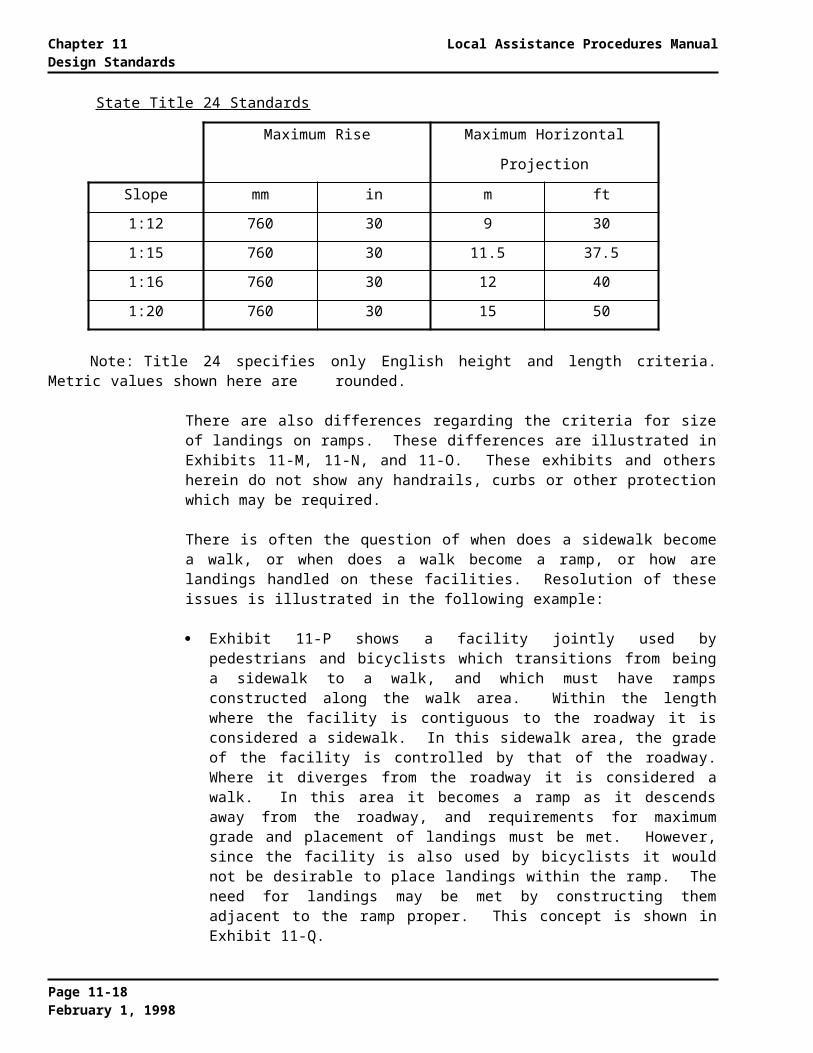
Local Assistance Procedures Manual Chapter 11Design Standards
For locally sponsored projects on the State Highway System, the Caltrans Standard Plans must be used.
STANDARD SPECIFICATIONS
The following standard specifications are acceptable for use on all local federal-aid projects not located on the State highway system:
The current edition of Caltrans Standard Specifications
The current edition of the Standard Specifications for Public Works Construction (commonly referred to as the “Green Book”), written and promulgated by the American Public Works Association, Southern California Chapter, and the Associated General Contractors of California, Southern California Districts.
Local standard specifications may be used for projects on the NHS, provided they have been reviewed and approved for such use by Caltrans.
For locally sponsored projects on the State Highway System, Caltrans Standard Specifications must be used.
11.3 LOCALLY DEVELOPED DESIGN STANDARDS
Plans and specifications for federal-aid highway projects shall provide for a facility that adequately meets the existing and probable future traffic in a manner conducive to safety, durability and economy of maintenance. Section 109, “Standards,” of Title 23 of the U.S. Code also requires that projects shall be designed and constructed to conform to the particular needs of each locality.
Since statewide standards do not always meet the particular needs of each locality, local design standards that meet the following requirements are allowed on local federal-aid projects off the State highway system.
LOCAL GEOMETRIC STANDARDS
Local geometric design standards that have been developed for use on locally funded new and reconstruction, or 3R projects, may be used on federal-aid projects off the NHS if:
The standards have been approved by the County Board of Supervisors or the City Council, and
These standards must be signed by the City/County Public Works Director if he/she is a California registered Civil Engineer. If not, they may be signed by the City/County Engineer if registered. If the City/County Engineer is not registered, the delegation can be made to the highest level engineer in the agency who is registered. Locally adopted design standards may be signed by a consultant on retainer as City/County Engineer if such individual is registered and is responsible directly to the Public Works Director or City/County Manager.
LOCAL PAVEMENT STRUCTURAL SECTION
Pavement structural section design methods or standards developed by a local agency for
Page 11-25February 1, 1998

Chapter 11 Local Assistance Procedures ManualDesign Standards
their own locally funded projects may be used for all local federal-aid projects off the NHS.
11.4 DESIGN EXCEPTIONS
Occasionally, project conditions may warrant an exception to certain accepted standards or procedures. Such conditions might include: extreme difficulty or high cost of obtaining right of way, cost of construction, or the mitigation of environmental impacts.
Although all deviations from accepted standards and procedures must be justified and documented in some manner and retained in the project files; not all design exceptions must adhere to the formal design exception procedures as described below.
STANDARDS FOR WHICH DEVIATIONS ARE PERMITTED
Deviations from accepted standards are permitted as follows:
Geometric Criteria -- The FHWA has determined that deviation from the following geometric control criteria for highways and bridges require formal approval:
- Design speed - Cross slope- Lane and shoulder width - Superelevation- Horizontal and vertical alignment - Horizontal and vertical clearance- Stopping sight distance - Bridge width- Grades
Any deviation from standards related to the above geometric criteria require that the local agency comply with the design exception approval procedures described below.
It is important to note that design exceptions that would result in the construction of a federally funded new bridge that would result in a Sufficiency Rating (SR) of less than 80 are not allowed. The controlling criteria for bridge width, vertical and horizontal over and under bridge clearances, and approach roadway alignment are among the factors that are rated during each biennial bridge inspection. Explanation of the rating factors can be found in the publication entitled Recording and Coding Guide for the Structure Inventory and Appraisal of the Nation’s Bridges.
Safety -- Deviations from the above geometric control criteria related to safety must be handled in accordance with the procedures outlined below. Deviations from the criteria contained in the other safety related publications referenced in Section 11.2 do not require special handling.
Pavement Structural Section -- Deviations from the pavement structural section design criteria referenced herein must be justified and documented in some manner, but do not require approval in accordance with the design exception approval procedures described below.
Drainage -- The hydrologic and hydraulic criteria contained herein is for guidance only. Deviations should be justified and documented, but do not require approval in accordance with the design exception approval procedures described below.
Bridge Railings -- Deviations from the nonstructurally related design criteria
Page 11-26February 1, 1998

Local Assistance Procedures Manual Chapter 11Design Standards
referenced herein do not require approval in accordance with the design exception approval procedures described below. Bridge rail on NHS projects let after August 16, 1998 must meet crash test requirements of NCHRP 350.
Bikeways -- Deviations from the “Mandatory Standards,” as defined and indicated in the Caltrans Highway Design Manual, require approval in accordance with the design exception approval procedures described below.
Pedestrian Facilities -- Deviations from the State pedestrian standards referenced herein shall be approved by the DSA. Deviation from federal pedestrian standards shall be documented in a form of a memo to file and retained in the project files. This memo shall discuss the justification and reasoning for not meeting the applicable standard.
STANDARDS FOR WHICH DEVIATIONS ARE NOT PERMITTED
Bridge Structural Capacity -- Deviations from the criteria contained herein for the structural capacity of bridges and other structures are not allowed. Deviations from bridge design details in the various Caltrans bridge design manuals and publications referenced herein are permitted as long as they do not impact structural capacity.
Signs and Markings -- Deviations from the “Mandatory Standards” for signs and markings as defined and indicated in the Caltrans Traffic Manual are not allowed.
DESIGN EXCEPTION APPROVAL PROCEDURES
LOCAL PROJECTS ON THE STATE HIGHWAY SYSTEM
Local projects on the State highway system must follow the design exception approval procedures outlined in the Caltrans Project Development Procedures Manual.
LOCAL PROJECTS NOT ON THE STATE HIGHWAY SYSTEM
The following design exception approval procedures are to be followed.
The FHWA has delegated Caltrans approval authority for design exceptions on local projects not on the State highway system. However, since local agencies are in a better position to assess applicability to any given situation on local roads; design exception approval authority (for those standards from which deviations are permitted) is now delegated to the City and County Public Works Directors. Public Works Directors may delegate this approval authority within their local agency if the Public Works Director is not a registered civil engineer in the State of California or if the local agency has a large engineering staff with multiple layers of responsibility. The person with approval authority must be a registered civil engineer in the State of California. Approval of design exceptions on local federal-aid projects shall be signed by the Public Works Director or the person to whom approval authority has been delegated.
The approval authority for design exceptions may be delegated to a private consulting firm that is on retainer as City or County Engineer.
To facilitate process reviews (see Chapter 19 of this manual), local agencies are required to keep copies of design exception forms in their project files. If any local agency fails to complete and retain design exception forms, their delegation to approve future design exceptions may be rescinded.
Page 11-27February 1, 1998

Chapter 11 Local Assistance Procedures ManualDesign Standards
DESIGN EXCEPTION FACT SHEET
The standard “Design Exception Fact Sheet” (Exhibit 11-F) must contain the following information:
Existing conditions Proposed work and nonstandard features Standard for which the exception is required Accidents - if applicable Design year traffic volumes - if applicable Added cost to make standard Description of any additional work to enhance safety Reason for requesting exception Reviews
The Design Exception Fact Sheet must be signed, stamped with engineer’s seal, and approved by Director of Public Works or the person to whom approval authority has been delegated
TRACKING OF DESIGN EXCEPTIONS
A tracking system for design exceptions should be implemented by local agencies to retrieve project information quickly and accurately. The data should include:
Project description Project location Nonstandard features approved Indication if future commitments have been made Brief description of commitments to upgrade the project to design standards at a
future date
11.5 REFERENCES
1. American Association of State Highway and Transportation Officials (AASHTO)
A Policy on Geometric Design of Highways and Streets, 1994 Guide Specifications for Bridge Railings, 1989 Roadside Design Guide, 1995 Standard Specifications for Highway Bridges, 1992
Page 11-28February 1, 1998

Local Assistance Procedures Manual Chapter 11Design Standards
2. California Department of Transportation (Caltrans) Bank and Shore Protection, 1970 Bridge Design Aids, current edition Bridge Design Details, current edition Bridge Design Practice Manual, current edition Bridge Design Specifications, current edition Bridge Memo to Designers, current edition Vehicle Crash Tests of Steel Bridge Barrier Rail Systems for Use on Secondary
Highways, Final Report # FHWA/CA/TL-93/01, Division of New Technology, Materials and Research
Flexible Pavement Structural Section Design Manual Flexible Pavement Structural Section Guide for California Cities and Counties Highway Design Manual
- Chapter 80 -- Application of Design Standards- Chapter 600 -- Design of the Pavement Structural Section- Chapter 800 -- Highway Drainage Design- Chapter 1000 -- Bikeway Planning and Design
Local Assistance Procedures Manual Local Assistance Environmental Manual Project Development Procedures Manual, current edition Standard Plans Standard Specifications Traffic Manual
3. Federal Highway Administration (FHWA)FHWA Internet Home Page: http://www.FHWA.DOT.GOV
23 USC Standards Federal-Aid Policy Guide, Subchapter G, Engineering and Traffic Operations,
Part 625 - Design Standards for Highways 23 CFR Part 650 Bridges, Structures and Hydraulics Hydraulic Engineering Circulars
- Design of Riprap Revetment - Hydraulic Engineering Circular #11, - Evaluating Scour at Bridges - Hydraulic Engineering Circular #18,- Stream Stability at Highway Crossings - Hydraulic Engineering Circular #20,
Manual on Uniform Traffic Control Devices Recording and Coding Guide for the Structure Inventory and Appraisal of the
Nation’s Bridge, Report No. FHWA-ED-89-044
4. Other Designing Safer Roads - Practices for Resurfacing, Restoration and
Rehabilitation, Special Report 214, Transportation Research Board Roadside Safety, Transportation Research Record 1065, Transportation Research
Board Recommended Procedures for the Safety Performance Evaluation of Highway
Appurtenances, National Cooperative Highway Research Program Report 230 Multiple-Service-Level Highway Bridge Railing Selection Procedures, National
Cooperative Highway Research Program Report 239 Standard Plans for Public Works Construction, developed and promulgated by
the American Public Works Association, Southern California Chapter, and the Associated General Contractors of California, Southern California Districts
Standard Specifications for Public Works Construction, developed and promulgated by the American Public Works Association, Southern California Chapter, and the Associated General Contractors of California, Southern
Page 11-29February 1, 1998
Chapter 11 Local Assistance Procedures ManualDesign Standards
California Districts Recommended Procedures for the Safety Performance Evaluation of Highway
Features, Report 350
Page 11-30February 1, 1998

Local Assistance Procedures Manual EXHIBIT 11-AGeometric Design Standards for Local 3R Projects
GEOMETRIC DESIGN STANDARDS FOR LOCAL 3R PROJECTS
Table 11-1: Lane and Shoulder Widths Arterial Roads and StreetsDesign Year Design Lane Shoulder Total Roadway
Volume Speed Width Width [a] Width (ADT) (km/h) (meter) (meter) (meter)
Low Volumes:1 - 750 ADT All 3.0 0.6 7.2
High Volumes:751 - 2,000 ADT All 3.6 0.6 [b] 8.4 [c]
Over 2,000 ADT All 3.6 1.8 [b] 10.8 [c]
[a] All shoulders on rural and urban arterials to be paved.[b] Reduce by 0.3 meter for highways on mountainous terrain.[c] Reduce by 0.6 meter for highways on mountainous terrain.
Table 11-2: Lane and Shoulder Widths Collector Roads and StreetsDesign Year Design Lane Shoulder Total Roadway
Volume Speed [a] Width Width [b] Width (ADT) (km/h) (meter) (meter) (meter)
Low Volumes:1 - 750 ADT All 3.0 0.6 7.2
High Volumes:751 - 2,000 ADT Under 80 3.0 0.6 [c] 7.2 [d]
80 and over 3.6 0.6 [c] 8.4 [d]Over 2,000 ADT All 3.6 1.2 [c] 9.6 [d]
[a] Highway segments should be classified as “under 80” only if most vehicles have an average speed of less than 80 km/h over the length of the segment
[b] All shoulders on collector roads and streets to be paved.[c] Reduce by 0.3 meter for highways on mountainous terrain.[d] Reduce by 0.6 meter for highways on mountainous terrain.
Table 11-3: Lane and Shoulder Widths Local Roads and StreetsDesign Year Design Lane Shoulder Total Roadway
Volume Speed [a] Width Width Width (ADT) (km/h) (meter) (meter) (meter)
Low Volumes:1 - 750 ADT All 3.0 0.6 7.2
High Volumes:751 - 2,000 ADT Under 80 3.0 0.6 [b] 7.2 [c]
80 and over 3.6 0.6 [b] 8.4 [c]Over 2,000 ADT All 3.6 1.2 [b] 9.6 [c]
[a] Highway segments should be classified as “under 80” only if most vehicles have an average speed of less than 80 km/h over the length of the segment
[b] Reduce by 0.3 meter for highways on mountainous terrain.[c] Reduce by 0.6 meter for highways on mountainous terrain.
Page 11-31February 1, 1998

EXHIBIT 11-A Local Assistance Procedures ManualGeometric Design Standards for Local 3R Projects
Table 11-4: Lane Widths Urban Roads and StreetsType of Lane Minimum Width
(meter)
Curb LaneNo Parking Anytime [a] 3.3Part-time Use (peak hour/high volume/low speed) 2.7With Parking 5.1
Interior Lane 3.0Lane Adjacent to Median
Raised Curb 3.0Painted Median 3.0
Left-Turn LaneOne-Way (one lane only) 3.0Two-Way (continuous) 3.0
Bicycle Lane (Within Roadway)One-Way 1.2Bicycle Lane and Parking (One-Way) 3.6
[a] A 3.0 meter curb lane, with up to 0.6 meter wide gutter, may be used at intersections.
Table 11-5: Bridges on Arterial Roads and StreetsDesign Year
Volume(ADT)
Minimum Usable Bridge Width [a]
1 - 750751 - 2,000
2,001 - 6,000Over 6,000
Width of approach lanes [b]Width of approach lanes plus 0.6 meter each sideWidth of approach lanes plus 1.2 meter each sideWidth of approach lanes plus 2.4 meter each side
[a] If lane widening is planned as part of a 3R project, the usable bridge width should be compared with the planned width of the approaches after they are widened.
[b] Minimum usable bridge width to be 7.2 meter.
Table 11-6: Bridges on Collector Roads and StreetsDesign Year
Volume(ADT)
Minimum Usable Bridge Width [a]
1 - 750751 - 2,000
2,001 - 6,000Over 6,000
Width of approach lanes [b]Width of approach lanes plus 0.6 meter each sideWidth of approach lanes plus 1.2 meter each sideWidth of approach lanes plus 2.4 meter each side
[a] If lane widening is planned as part of a 3R project, the usable bridge width should be compared with the planned width of the approaches after they are widened.
[b] Minimum usable bridge width to be 7.2 meter.
Page 11-32February 1, 1998

Local Assistance Procedures Manual EXHIBIT 11-AGeometric Design Standards for Local 3R Projects
Table 11-7: Bridges on Local Roads and StreetsDesign Year
Volume(ADT)
Minimum Usable Bridge Width [a]
1 - 750751 - 2,000
Over 2,000
Width of approach lanesWidth of approach lanes plus 0.6 meter each sideWidth of approach lanes plus 1.2 meter each side
[a] If lane widening is planned as part of a 3R project, the usable bridge width should be compared with the planned width of the approaches after they are widened.
Table 11-8: Horizontal and Vertical Alignment Arterial Roads and Streets
MinimumStopping
Minimum Radius of Horizontal Curve
(meter)Maximum Grade
Design Sight Super- Super- Rural UrbanSpeed(km/h)
Distance(meter)
elevation10% (a)
elevation8% (b) Level Rolling Mountains Level Rolling Mountains
50 57.4 75 80 ... ... ... 8 9 1160 74.3 115 125 5 6 8 7 8 1070 94.1 160 175 5 6 7 6 7 980 112.8 210 230 4 5 7 6 7 990 131.2 275 305 4 5 6 5 6 8100 157.0 360 395 3 4 6 5 6 8
[a] Generally, superelevation should not exceed 10 percent.[b] Superelevation should not exceed 8 percent where snow and ice conditions prevail.
Table 11-9: Horizontal and Vertical Alignment Collector Roads and Streets
MinimumStopping
Minimum Radius of Horizontal Curve
(meter)Maximum Grade
Design Sight Super- Super- Rural UrbanSpeed(km/h)
Distance(meter)
elevation10% (a)
elevation8% (b) Level Rolling Mountains Level Rolling Mountains
30 29.6 25 30 7 10 12 9 12 1440 44.4 45 50 7 10 11 9 12 1350 57.4 75 80 7 9 10 9 11 1260 74.3 115 125 7 8 10 9 10 1270 94.1 160 175 7 8 10 8 9 1180 112.8 210 230 6 7 9 7 8 1090 131.2 275 305 6 7 9 7 8 10100 157.0 360 395 5 6 8 6 7 9
[a] Generally, superelevation should not exceed 10 percent.[b] Superelevation should not exceed 8 percent where snow and ice conditions prevail.
Page 11-33February 1, 1998

EXHIBIT 11-A Local Assistance Procedures ManualGeometric Design Standards for Local 3R Projects
Table 11-10: Horizontal and Vertical Alignment Local Roads and Streets
MinimumStopping
Minimum Radius of Horizontal Curve
(meter)Maximum Grade
Design Sight Super- Super- RuralSpeed(km/h)
Distance(meter)
elevation10% (a)
elevation8% (b) Level Rolling Mountains
30 29.6 25 30 8 11 1640 44.4 45 50 7 11 1550 57.4 75 80 7 10 1460 74.3 115 125 7 10 1370 94.1 160 175 7 9 1280 112.8 210 230 6 8 1090 131.2 275 305 6 7 10100 157.0 360 395 5 6 ...
[a] Generally, superelevation should not exceed 10 percent.[b] Superelevation should not exceed 8 percent where snow and ice
conditions prevail.
Page 11-34February 1, 1998

Local Assistance Procedures Manual EXHIBIT 11-BAASHTO Publications Order Form
AASHTO Publications Order Form FAX (202) 624-5806
American Association of State Highway and Transportation Officials444 N. Capitol St., N.W., Suite 249Washington, D.C. 20001 USA
Ship to:
Check enclosed (made payable to AASHTO)
Charge to: Mastercard Visa Card Number Exp. Date
Print cardholder’s name Daytime Phone ( )
CREDIT CARD ORDER MAY BE FAXED. DO NOT MAIL CONFIRMING COPY
Quantity Code Publication Title Unit Price Total Amount
PLEASE SubtotalALLOW 4-6WEEKS FOR Foreign Postage & HandlingDELIVERY
TOTAL
Association policy does not allow for discounts or permit returns of publications for refund or credit.Prices subject to change without notice. Have you enclosed the correct remittance?
Page 11-35February 1, 1998

EXHIBIT 11-B Local Assistance Procedures ManualAASHTO Publications Order Form
Page 11-36February 1, 1998

Local Assistance Procedures Manual EXHIBIT 11-CFoundation Investigations
FOUNDATION INVESTIGATIONFOR DESIGN
A foundation investigation and report is required for all proposed structure sites. The study and report shall be made by a California licensed Engineering Geologist or Civil Engineer, who specializes in foundations. The report shall, at a minimum, address all “applicable” topics shown in the following Caltrans checklist.
Specific attention is directed to appropriate sections of the Caltrans Bridge Design Specifications, Section 4- FOUNDATIONS. All driven pile support recommendations shall consider the use of Caltrans Standard Class 400 or Class 625 piles using design loads of 400 and 625 kilonewtons respectively.
A Log of Test Borings sheet shall be drafted and included as part of the foundation report, and as part of the structure plans.
CHECKLIST FOR STRUCTURE FOUNDATION STUDIESAND REPORTS
LOG OF TEST BORINGS SHEET
A log of Test Borings sheet (similar to Caltrans’ sheet) shall be included as part of the Foundation Report. Show the location of each boring or test pit in plan view. Logs of all borings shall be shown in an elevation or profile view on the sheet. Information which should be shown on plots of test borings is as follows:
1. Diameter, type, and date of boring.
2. Location of borings with respect to stationing along survey lines for the proposed project.
3. Elevation of the top of each boring, etc.
4. Description of samplers, sampling methods, and in-situ tests.
5. Test results including Standard Penetration Test. Results of the Standard Penetration Test (ASTM D-1586-84) shall be presented so that quick correlation with the Caltrans data base may be made.
6. Soil or rock descriptions and elevations of strata.
7. Groundwater elevation and date of measurement should be shown adjacent to the boring or test pit where taken.
8. Location, description, and elevation or the benchmark used for determining the top-of-hole elevations shown on the Log of Test Borings.
9. Name and position or title of person conducting the field study.
10. Name and position or title of the registered Engineering Geologist or Civil Engineer approving the “Log of Test Boring Sheet.”
Page 11-37February 1, 1998
EXHIBIT 11-C Local Assistance Procedures ManualFoundation Investigations
WRITTEN REPORT
A written report shall be prepared which will contain an interpretation and analysis of the foundation conditions based upon all available sources of data. Data may come from new or previous exploration programs, laboratory testing, and nearby construction experience, performance of nearby existing structures, etc. A short description of site topography geology should be included. Emphasis should be placed on slope stability of cuts and excavations, unusual groundwater conditions, springs, etc. All sources of information should be cited. The materials and conditions, which may be encountered during construction, shall also be discussed. Problems involving design and construction should be anticipated, and recommendations made for their solution. The recommendations shall be brief, concise, and definite. Reasons for recommendations and their supporting data shall always be included. Methods used for calculating pile capacities and soil bearing capacities should be mentioned for ease of review. Extraneous data, which are of no use to the designer or Resident Engineer, should be omitted.
The written report shall include, but not be limited to, information and recommendations regarding applicable items in the following list:
I. TYPE OF FOUNDATION
A. Pile Support (Driven or Cast-In-Drilled-Hole)
1. Method of support (skin friction and/or end bearing) in rock or soil or both.
2. Suitable pile type(s) - reasons for choice and/or exclusion or types. When appropriate, Caltrans’ standard piles should be used.
3. Pile tip elevations.
a. Specified (use of “indicator piles” is not acceptable.)b.Probablec. Need for pre-drilling or jetting.
4. Pile Design Load and Ultimate Capacity in compression and tension. Specify the Safety Factor.
5. Reduction of pile capacity due to negative skin friction.
6. Requirement for load test. Specify which portion of the structures’ foundation will be controlled by the test.
7. Effects on adjacent existing structures.
8. Corrosion effects of various soils and waters, and possibility of galvanic reaction from stray currents.
9. Scour depth (elevation) and method of determination.
B. Footing Support
1. Elevation of bottom of footing.
2. Allowable and ultimate footing pressure (include Safety Factor). Approximate settlement at uniformly distributed allowable load.
3. Brief description of material on which the footing is to be placed.4. Scour depth (elevation).
Page 11-38February 1, 1998

Local Assistance Procedures Manual EXHIBIT 11-CFoundation Investigations
C. Drilled shafts / Pier Columns (Mined Shafts)
1. Geologic description of foundation materials.
2. Diameter (or dimensions).
3. Design load, ultimate load, and Safety Factor.
4. a. Top of shaft elevation.b. Bottom of shaft elevation.c. Minimum shaft length into load carrying stratum.d. Estimate of shaft wall stability and possible shoring requirements.
5. Soil or rock weight and strength parameters for determining end bearing capacity, lateral load capacity and point of shaft/column fixity.
II. APPROACH FILL REQUIREMENTS
1. Predicted amount of settlement and time delay required prior to beginning foundation construction. Predicted post construction settlement. Possibility of negative friction on pile foundations.
2. Special Requirements:a. Controlled rates of embankment placement.b. Fill height limit on untreated foundation.c. Stripping of unsuitable foundation material.d. Use of lightweight fills to reduce amount of settlement.e. Use of surcharge, wick drains, or other methods to shorten the required time delay period.f. Specify embankment side slopes.g. Unusual compaction requirements (i.e. 95% relative compaction) where abutments on spread
footings are used.
III. CONSTRUCTION CONSIDERATIONS
1. Water table - seasonal or long term fluctuations, data for possible control in excavations (i.e. pumping, well points, trim seals, amounts of groundwater, etc.).
2. Adjacent structures - protection against damage from excavations, pile driving, etc.
3. Pile driving- difficulties, clearance, overhead or underground utilities, other unusual conditions, etc.
4. Excavation - control of earth slopes including shoring, sheet piles, bracing, and safety requirements.
IV. SEISMIC DATA
The foundation report should contain the following information, so that an evaluation of seismicity can be made per the Caltrans Bridge Design Specifications.
1. Maximum credible rock acceleration (from CDMG MS-45*).
2. Magnitude of the maximum credible event.
3. Name of the causative fault and distance from the site.
Page 11-39February 1, 1998

EXHIBIT 11-C Local Assistance Procedures ManualFoundation Investigations
4. Depth to rock or rock-like material (Vs > 762 m/s) Provide supporting evidence for depth (i.e. boring log or geologic reference).
5. Liquefaction potential.
6. Need for “seismic approach slab.”
V. REVIEW OF FINAL STRUCTURE PLANS
The foundation consultant should review the structure plans to ensure that the foundation recommendations have been followed, and provide revised recommendations, if required by design changes, etc.
*Mualchin, Lalliana (1987) California Division of Mines and Geology Map Sheet 45, Rock Acceleration from Maximum Credible Earthquakes In California.
Page 11-40February 1, 1998

Local Assistance Procedures Manual EXHIBIT 11-DPreliminary Hydrologic/Hydraulic Review Summary
PRELIMINARY HYDROLOGIC/HYDRAULIC REVIEW SUMMARY
Bridge Name (facility crossed)
State Bridge No. Road Name
Hydrologic and Hydraulic Data
1. Size of drainage basin
2. Design flows and water surface elevations (USGS)
a. Q10 elevation (culverts only)b. Q50 elevationc. Q100 elevation
3. High water marks (Elevation/Year)
4. Structure opening size Date Constructed
a. Existingb. Upstreamc. Downstream
5. Description of property risks
6. Summary of upstream development
7. Importance of structure
8. Description of risks to life
9. Effects of facility on stream environment
10. Are there any channel restrictions or controlled flow?
11. Has this basin been studied before? Date of study? Is the Study recognized by Caltrans?
12. Is there a potential debris problem? (describe)
13. Are there any mining operations within one kilometer upstream and/or downstream?
Remarks:
Page 11-41February 1, 1998
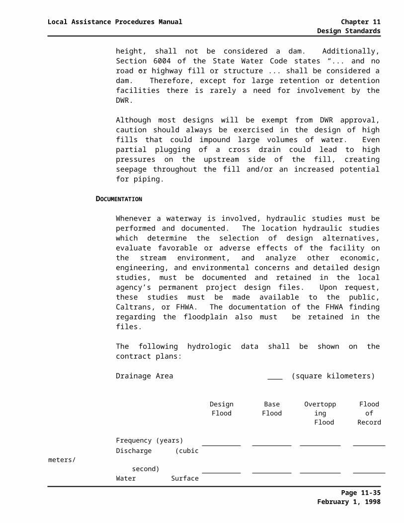
EXHIBIT 11-D Local Assistance Procedures ManualPreliminary Hydrologic/Hydraulic Review Summary
Page 11-42February 1, 1998

Local Assistance Procedures Manual EXHIBIT 11-EChecklist for Drainage Studies and Reports
CHECKLIST FOR DRAINAGE STUDIES AND REPORTS
This is a checklist of items to be considered for inclusion in hydraulic studies and reports. For definition of terms see section entitled “Glossary of Pertinent Terms” of this chapter.
1. PRELIMINARY
a. Review of basic guidelines
(1) A floodplain cannot be altered in any way until it has been shown that such alteration will pass the base flood without significant damage to either the floodplain or surrounding property. This requirement is often referred to as “conveyance of the base flood.” (Conveyance may be through structures, over the roadway, through escapements, through overflow channels, or any combination of the above.)
(2) Approval for actions within a floodplain cannot be given until various options of alignments, grade, and waterway area have been appraised.
(3) No bridge abutments or embankment shall encroach on a regulatory floodway.
b.Collect appropriate and readily available published data such as:
(1) USGS quadrangle maps
(2) NFIP maps - Floodplain maps may be obtained from the National Flood Insurance Program (NFlP), or the Local Caltrans District office
(3) Aerial photos - Check with Caltrans
(4) Runoff records - USGS water supply papers
(5) Rainfall records- Various sources
(6) Prior hydrology reports including photos and plans
c. Coordinate with other agencies
(1) Determine whether permits are required
(2) Determine how the area is zoned
(3) Investigate possibility of cooperative projects
(4) Determine whether there are existing or proposed water resource projects that will influence the design, and summarize details (Watershed area, storage capacity, etc., when pertinent)
(5) Determine whether there is ongoing or proposed clearing, construction, land leveling, land development, aggregate mining, etc., that would affect flow in or the stability at the stream
d.Floodplain Encroachments
(1) Executive order 11988 establishes the federal policy on floodplain management. This policy has been implemented by Title 23 CFR, Part 650A (23 CFR 650A).
Page 11-43February 1, 1998

EXHIBIT 11-E Local Assistance Procedures ManualChecklist for Drainage Studies and Reports
(2) CFR 650A requires all encroachments and all actions which affect an area subject to flooding by flood or tide having a one-percent chance of being exceeded in any given year, to comply with a floodplain management policy. Repairs made to existing facilities with emergency funds (see Local Programs Manual which discusses Emergency Relief) during or immediately following a disaster are exempt from this policy.
e. The hydrology and hydraulics report shall:
(1) Only be as comprehensive as the conditions warrant. Calculations with short comments are sufficient for a culvert in a well defined drainage environment. A complete comprehensive document is required for a major stream crossing in an ecological setting.
(2) Generally be structured along these guidelines with:
(a)Background data and estimates of future flood
(b)Calculations to determine velocities, water surface elevations, backwater and scour depth (the lead agency should provide a disk with the data used to run HEC-2 or WSPRO. If a program other than these is used, that program should be provided on a disc along with the data used).
(c)Illustrative photos
(d)Comments on selection of design flood, conveyance of 100-year flood, channel change, effect on stream stability, and provisions for fish passage
f. Suggested desirable hydraulic features
(1) The following features should be considered in the design of a bridge or culvert:
(a) Use of warped wingwalls
(b) No open vents
(c) No piers in main channel
(d) Use of energy dissipaters
(e) Extending pier walls to edge of deck
(f) No piers in navigable channel
2. FIELD RECONNAISSANCE -- Should be made by the engineer making the hydrologic and hydraulic analysis
a. Channel stability
(1) Estimate the erodability of streambed material
(2) Document bends, meanders, and any eroded areas
(3) Is the existing protection providing adequate erosion control, and if so, is it fragile?
(4) Are there signs of aggradation or degradation? Other scour considerations?
(5) Are there any upstream or downstream mining operations?
b.Potential problems
Page 11-44February 1, 1998

Local Assistance Procedures Manual EXHIBIT 11-EChecklist for Drainage Studies and Reports
(1) Consideration of the value of the property that would be damaged by the base flood or overtopping flood
(2) Size and amount of drift
(3) Ice, snow
(4) Banks that would erode if flow is accelerated or redirected
(5) Check adequacy of abutment protection
c. Environmental considerations
(1) Beauty of area
(2) Fish habitat and wildlife cover
(3) Will local water supply or sanitation treatment facility be affected?
(4) Is it within a park or recreation area?
(5) See “Flood Plain Values” (see Local Programs Manual, Volume III, Chapter 9)
d.Alternative sites
(1) Locate suitable alternative sites
(2) What are the advantages and disadvantages of the alternative sites?
e. Existing structures (including relief or overflow structures)
(1) Locate existing nearby upstream or downstream structures with respect to proposed crossing or encroachment
(2) For each existing nearby structure note the type, number of spans, span lengths, vertical clearance, bent design or pier orientation
(3) For each nearby existing culvert estimate the size and number of cells
f. Hydraulic data
(1) Locate high water marks (give date and elevation)
(2) Document both the flood history and source of information
(3) Document the damage to existing structures including abrasion, corrosion, wingwall failure, culvert entrance failure, pier settlement, or excessive aggradation or degradation
(4) Note the use of bank protection, drop structures, or any other sign of corrective work at existing structures
g.Factors affecting water stage
(1) Determine whether flood flow can escape to, or enter from, other watersheds during floods.
Page 11-45February 1, 1998

EXHIBIT 11-E Local Assistance Procedures ManualChecklist for Drainage Studies and Reports
(2) Determine whether any of the flow can bypass the site.
(3) Determine whether backwater or tides affect the flow.
(4) Determine what will control an overtopping flood.
3. ECONOMIC ANALYSIS
a. Make an economic analysis of all the reasonable alternatives based on construction cost, aesthetic cost, ecological cost, flood damage cost, loss of traffic service, etc.
b. Reject from further considerations those options that are not economically suitable alternatives.
4. FIELD SURVEY
a. Obtain topographic data for the suitable site alternatives. Extend limits to include overflows where practicable.
b.Locate, sketch, and record significant features such as buildings, levees, walls, fences, ditches, trees, boulders, etc., and where significant, record elevations.
c. Record water surface elevation, the elevation of the path of greatest depth as in a stream channel (thalweg elevation), and estimate velocity of flow.
d.Set tidal gages where tidal influence is possible and record data hourly throughout the survey.
e. Obtain channel cross sections 150 and 300 meters upstream and downstream where necessary.
f. Obtain data on boat traffic.
g.Take ample photographs at each site to illustrate the hydraulic and ecological features.
h.Take physical measurements of the existing structure and/or any other bridge or culvert with similar characteristics either upstream or downstream.
i. Where possible determine the foundation type (spread footings, piles) and foundation depth of all nearby structures.
5. SITE MAP CONSTRUCTION
a. Purpose: For use in estimating flood flow distribution; to locate cross section of stream; to show location of proposed encroachment and structures, alignment of piers, skew of crossing, stream controls, existing encroachments, existing highway structures, etc.
(1) A specially prepared site map showing .25- or .50-meter contours, vegetation, and manmade improvements is normally required. In some cases cross sections normal to flood flow are acceptable in lieu of the map. A minimum of 3 cross sections are required including one upstream, one at the crossing, and one downstream.
(2) The site map should include the limits of the overtopping flood when practical.
(3) Where there are two or more suitable alignments, a site map must be prepared for each.
6. HYDROLOGIC ANALYSIS
a. Hydrologic considerations
Page 11-46February 1, 1998

Local Assistance Procedures Manual EXHIBIT 11-EChecklist for Drainage Studies and Reports
(1) Determine drainage area above the proposed encroachment. Subdivide where runoff characteristics are or will be significantly different.
(2) List available flood records at the encroachment and/or at nearby hydraulically similar watersheds.
(3) Calculate the flow at the proposed encroachment for the base flood and the design flood, if different. Include any other flow within the floodplain that affects the design of the project. The flood calculations should be made by using at least two widely used methods. Nearby stream gage data may be used, if the data is adequate to furnish the above.
(4) Plot the flood frequency curve.
(5) Plot the stage discharge curve.
b.Establish the existing flow conditions.
(1) Determine the distribution of flow and velocities for several discharges or stages in the natural channel for existing conditions. USCE, USGS, FEMA, etc., studies may be used as a general case .
(2) Establish the maximum permissible upstream water surface for base flood.
c. Hydraulic design for bridges
(1) Compute the water surface profile for various trial bridge lengths and discharges at each of the alternative sites. If alternate alignments are proposed compute the water surface profile for various trial bridge lengths and discharges at each of the alternative sites.
(The Lead Agency should provide a disc with the data used to run the HEC-2 or WSPRO water surface profile computer programs. If a program other than HEC-2 or WSPRO is used that program should be provided on a disc along with the data used.)
(For the base flood, backwater caused by the encroachment together with that caused by all other man-made obstructions is limited to 0.3 meter above the water surface of the base flood.) Design must be in accordance with 23 CFR 650A. The local agency must comply with FEMA’s regulatory floodplain rules or they may lose their federal flood insurance.
(2) Select alignment, grade, bridge type and size waterway openings, etc., on the basis of overall economic calculations and freeboard requirements (see Section 10, “Design Standards”).
(3) Check “conveyance of base flood.”
(4) Calculate scour depth at piers. (Recommended reference HEC-18 “Evaluating Scour at Bridges,” FHWA)
(5) Design pertinent features such as riprap for bank protection, cross channel stabilizers for streambed control, energy dissipaters to reduce downstream velocities, spur dikes to equalize flow, etc. (Recommended references are HEC - 18 “Evaluating Scour at Bridges” and HEC - 20 “Stream Stability at Highway Structures”)
Page 11-47February 1, 1998
EXHIBIT 11-E Local Assistance Procedures ManualChecklist for Drainage Studies and Reports
d.Hydraulic design for culverts (Recommended reference; Caltrans Highway Design Manual)
(1) Determine allowable headwater elevation.
(2) Compute and plot performance curves for trial culvert sizes at alternate alignments.
(3) Evaluate erosion, abrasion, and corrosion potentials.
(4) Select alignment, grade, culvert design on the basis of overall economic calculations related to the design standards appropriate to the project.
e. Hydraulic design for longitudinal encroachments
(1) Determine the effect of the proposed encroachment on water surface profile using various roadway design, alternatives, and the base flood.
(2) Evaluate the effects on scour and deposition in the channel.
(3) Select roadway design on the basis of overall economic calculations.
(4) Design pertinent features such as bank protection, etc. (Recommended reference HEC-11 Design of Riprap Revetment, FHWA and/or Bank and Shore Protection, Caltrans)
7. CONTRACT PLANS
The following data shall be shown on the contract plans, and may be shown in tabular form. List the frequency, magnitude and pertinent water surface elevations for:
a. Minimum Design Flood
b.Base Flood
c. Overtopping Flood
d.Flood of Record, if available
The data used for design must be designated and if different from the above, the data must be shown on the plans.
HYDRAULIC REFERENCES
1. Guidelines for Hydraulic Considerations in Highway Planning and Location , Volume I, Highway Drainage Guidelines, AASHTO, 1990.
2. Guidelines for Hydrology, Volume II, Highway Drainage Guidelines, AASHTO, 1992.
3. Highway Hydrology, HDS No.2, FHWA-SA-96-067, 1996.
4. Flood-frequency analysis, such as those of U. S. Geological Survey or other water-resources agencies, for the region in which the structure is located.
5. Highways in the River Environment Hydraulic and Environmental Design Considerations , U.S. Department of Transportation, FHWA, 1983
Page 11-48February 1, 1998

Local Assistance Procedures Manual EXHIBIT 11-EChecklist for Drainage Studies and Reports
6. Stream Stability at Highway Structures, HEC-20, FHWA-0IP-90-014, 1991
7. Bradley, J. N., 1979, Hydraulics of Bridge Waterways, Hydraulic Design Series No. l, Federal Highway Administration, U.S. Government Printing Office, Washington, DC, 1978, 111 p.
8. Evaluating Scour at Bridges, Second Edition, HEC-18, FHWA-IP-90-017, 1993.
9. Highway Research Board, 1979, Scour at Bridge Waterways, National Cooperative Highway Research Program Synthesis 5, Highway Research Board, National Academy of Sciences, 2101 Constitution Avenue, Washington, DC 20418.
10. Hydraulic Design of Highway Culverts, September 1985, Hydraulic Design Series No.--, Report No. FHWA-1P-85-15.
11. Circular Memorandum, G. M. Williams, July 21, 1966 Plans for Pipe Culvert Inlet and Outlet Structures, Federal Highway Administration.
12. Guidelines for Hydraulic Design of Culverts, Volume IV, Highway Drainage Guidelines, AASHTO, 1992.
13. Searcy, J. K., Design of Roadside Drainage Channels, 1985, Federal Highway Administration, Hydraulic Design Series No. 4, U.S. Government Printing Office, Washington, DC.
14. Bridge Deck Drainage Systems, HEC-21, FHWA-SA-92-010, 1993
15. Local Assistance Environmental Manual, Chapter 9.
16. Design of Encroachments on Flood Plains Using Risk Analysis, HEC 17, FHWA-EPD-86-112, 1981
17. For information regarding flood plain delineation studies, write to: Department of Housing and Urban Development, Federal Insurance Administration, Assistant Administrator for Flood Insurance, 451 7th Street, SW, Washington, DC 20410
18. Design of Rip rap Revetment, HEC-11, FHWA-1P-89-016,1989.
19. Caltrans Highway Design Manual
20. AASHTO Model Drainage Manual
Page 11-49February 1, 1998

EXHIBIT 11-E Local Assistance Procedures ManualChecklist for Drainage Studies and Reports
Page 11-50February 1, 1998
Local Assistance Procedures Manual EXHIBIT 11-FDesign Exception Fact Sheet
DESIGN EXCEPTIONFACT SHEET
Dist: Date: Co: Prepared by: Rte: Project Cost:
1. Existing Conditions
2. Proposed Work and Non-Standard Features
3. Standard for Which Exception is Required
4. Accidents 3-year PeriodTotal F F+I Actual Rate Expected Rate
Describe type(s) of accidents that are occurring and what effect the design exception is expected to have on them.
5. Design Year Traffic Volumes
6. Added Cost to Make Standard
7. Description of Any Additional Work to Enhance Safety
8. Reason for Requesting Exception
EXCEPTION APPROVED: DATE Public Works Director (or Delegate Title)
Page 11-51February 1, 1998

EXHIBIT 11-F Local Assistance Procedures ManualDesign Exception Fact Sheet
INSTRUCTIONS FOR “DESIGN EXCEPTION FACT SHEET”
1. Existing ConditionsDescribe existing facility. Number of lanes, median width, shoulder width, etc. Describe width of adjoining sections if that information is relevant, for example, on 3R projects.
2. Proposed Work and Non-Standard FeaturesDescribe work to be done. Resurfacing, shoulder widening, bridge widening, etc. Describe the non-standard design element that required the exception.
3. Standard for Which Exception is RequiredBe specific. Name the source, i.e., 3R Criteria, Instructions for AASHTO Green Book Implementation, or Highway Design Manual.
4. Accidents 3-year PeriodTotal F F+I Actual Rate Expected Rate
5. Design Year Traffic VolumesIf 3R project, use construction year. Otherwise use design year, usually 20 years.
6. Added Cost to Make StandardShow what it would cost to meet the standard for which the exception is being requested. If more than one quadrant is involved in the approach rail design request, cost shall be broken down on a per quadrant basis. The Fact Sheet should also be accompanied with a detailed drawing of the bridge site along with topographical features (right of way lines, side road widths, physical obstructions, etc.) 30m from beginning and ending of the bridge.
7. Description of Any Additional Work to Enhance SafetyMention any additional work which would qualify for safety enhancement such as median barrier, guardrail upgrade, slope flattening, super correction, elimination of roadside obstacles, additional lane and shoulder width, alignment improvement, etc.
8. Reason for Requesting ExceptionBe thorough, but brief. These are some, but not all of the reasons exception have been granted in the past: high cost; environmental sensitivity; low accident rates; postponement of bridge work.
Page 11-52February 1, 1998

Local Assistance Procedures Manual EXHIBIT 11-GAlternative Curb Ramp Shape
Page 11-53February 1, 1998

EXHIBIT 11-G Local Assistance Procedures ManualAlternative Curb Ramp Shape
Page 11-54February 1, 1998

Local Assistance Procedures Manual EXHIBIT 11-HBuilt - Up Curb Ramp
Page 11-55February 1, 1998

EXHIBIT 11-H Local Assistance Procedures ManualBuilt - Up Curb Ramp
Page 11-56February 1, 1998

Local Assistance Procedures Manual EXHIBIT 11-ICurb Ramp With Vertical Sides
Page 11-57February 1, 1998

EXHIBIT 11-I Local Assistance Procedures ManualCurb Ramp With Vertical Sides
Page 11-58February 1, 1998

Local Assistance Procedures Manual EXHIBIT 11-JCenter Island With Slot for Accessibility
Page 11-59February 1, 1998

EXHIBIT 11-J Local Assistance Procedures ManualCenter Island With Slot for Accessibility
Page 11-60February 1, 1998

Local Assistance Procedures Manual EXHIBIT 11-KSlots Through Island at Right-Turn Lane
Page 11-61February 1, 1998
EXHIBIT 11-K Local Assistance Procedures ManualSlots Through Island At Right-Turn Lane
Page 11-62February 1, 1998

Local Assistance Procedures Manual EXHIBIT 11-LCenter Island With Curb Ramps
Page 11-63February 1, 1998
EXHIBIT 11-L Local Assistance Procedures ManualCenter Island With Curb Ramps
Page 11-64February 1, 1998

Local Assistance Procedures Manual EXHIBIT 11-MStraight Ramp Run
Page 11-65February 1, 1998
EXHIBIT 11-M Local Assistance Procedures ManualStraight Ramp Run
Page 11-66February 1, 1998
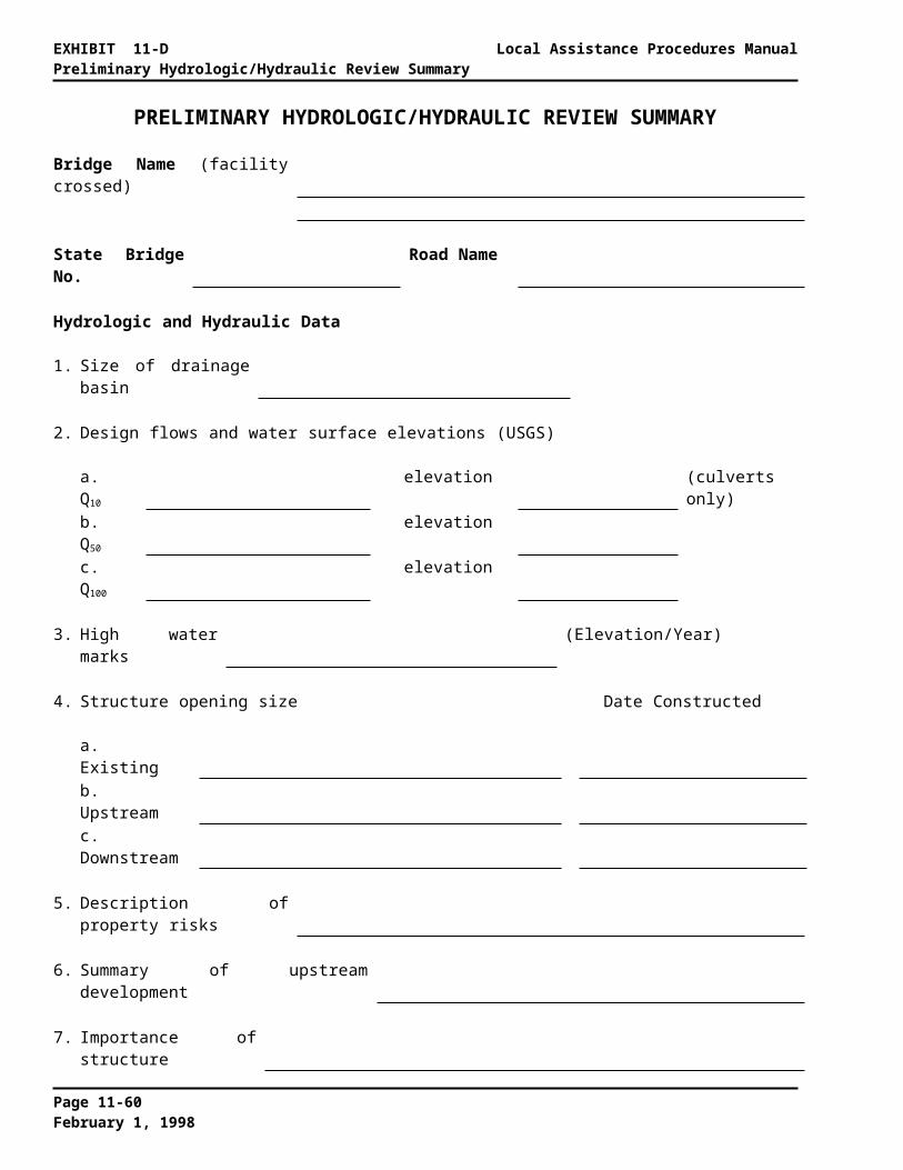
Local Assistance Procedures Manual EXHIBIT 11-NRamp With Intermediate Switch-Back Platform
Page 11-67February 1, 1998

EXHIBIT 11-N Local Assistance Procedures ManualRamp With Intermediate Switch-Back Platform
Page 11-68February 1, 1998

Local Assistance Procedures Manual EXHIBIT 11-ORamp With Turning Platform
Page 11-69February 1, 1998

EXHIBIT 11-O Local Assistance Procedures ManualRamp With Turning Platform
Page 11-70February 1, 1998
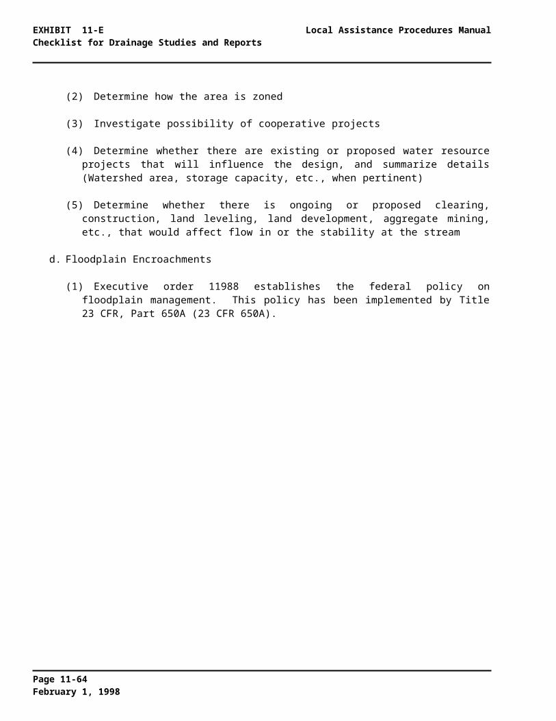
Local Assistance Procedures Manual EXHIBIT 11-PTransition From Sidewalk to Walk
Page 11-71February 1, 1998

EXHIBIT 11-P Local Assistance Procedures ManualTransition From Sidewalk to Walk
Page 11-72February 1, 1998
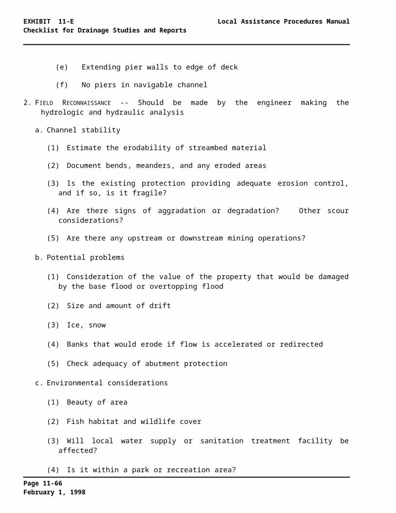
Local Assistance Procedures Manual EXHIBIT 11-QRamp Used Jointly By Pedestrians And Bicyclists
Page 11-73February 1, 1998

EXHIBIT 11-Q Local Assistance Procedures ManualRamp Used Jointly By Pedestrians And Bicyclists
Page 11-74February 1, 1998

Local Assistance Procedures Manual EXHIBIT 11-RSidewalk-Driveway Interface
Page 11-75February 1, 1998

EXHIBIT 11-R Local Assistance Procedures ManualSidewalk-Driveway Interface
Page 11-76February 1, 1998