
CHAPTER 9 – MANUFACTURING · NX 12 for Engineering Design 182 Missouri University of Science and...
37
NX 12 for Engineering Design 182 Missouri University of Science and Technology CHAPTER 9 – MANUFACTURING As we discussed in Chapter 1 about the product realization process, the models and drawings created by designers will undergo manufacturing processes to get to the finished products, which is the essence of CAD/CAM integration. The most widely and commonly used technique is to generate control codes for CNC machines to mill the desired part. This technique reduces the amount of human programing in creating CNC codes, which facilitates the designers to create products with complex geometries. In this chapter, we will cover the Manufacturing Module of NX 12 to generate CNC codes for 3-Axis Vertical Machining Centers. This module allows us to program and do some post-processing on drilling, milling, turning and wire-cut EDM tool paths. 9.1 GETTING STARTED A few preparatory steps need to be performed on every CAD model before moving it into the CAM environment. In this chapter, we are going to work with a model that was finished in the previous exercise problem. All the units are followed in millimeters in this model and manufacturing of the component. Before getting started, it would be helpful if you can get into a CAM Advanced Role. To do this, go to the Roles menu on the Resource Bar. Click Content and a list of choices will pop up in which the CAM Advanced role can be seen as shown in the figure. 9.1.1 Creation of a Blank After completing the modeling, you should decide upon the raw material shape and size that need to be loaded on the machine for the actual fabricating. This data has to be the input in NX 12. It can be achieved in two ways. The first method is creating or importing the model of the raw material as a separate solid in the same file and assigning that solid as the Blank. The second method is letting NX decide the extreme dimensions of the designed part and
Transcript of CHAPTER 9 – MANUFACTURING · NX 12 for Engineering Design 182 Missouri University of Science and...

NX 12 for Engineering Design 182 Missouri University of Science and Technology
CHAPTER 9 – MANUFACTURING
As we discussed in Chapter 1 about the product realization process, the models and drawings
created by designers will undergo manufacturing processes to get to the finished products, which
is the essence of CAD/CAM integration. The most widely and commonly used technique is to
generate control codes for CNC machines to mill the desired part. This technique reduces the
amount of human programing in creating CNC codes, which facilitates the designers to create
products with complex geometries. In this chapter, we will cover the Manufacturing Module of
NX 12 to generate CNC codes for 3-Axis Vertical Machining Centers. This module allows us to
program and do some post-processing on drilling, milling, turning and wire-cut EDM tool paths.
9.1 GETTING STARTED
A few preparatory steps need to be performed on every CAD model before moving it into the
CAM environment. In this chapter, we are going to work with a model that was finished in the
previous exercise problem. All the units are followed in millimeters in this model and
manufacturing of the component.
Before getting started, it would be helpful if you can get
into a CAM Advanced Role. To do this, go to the Roles
menu on the Resource Bar. Click Content and a list of
choices will pop up in which the CAM Advanced role can
be seen as shown in the figure.
9.1.1 Creation of a Blank
After completing the modeling, you should decide upon
the raw material shape and size that need to be loaded on
the machine for the actual fabricating. This data has to be
the input in NX 12. It can be achieved in two ways. The
first method is creating or importing the model of the raw
material as a separate solid in the same file and assigning
that solid as the Blank. The second method is letting NX
decide the extreme dimensions of the designed part and

NX 12 for Engineering Design 183 Missouri University of Science and Technology
some offset values if needed. The later method allows a quick way of assigning the size details but
it can only be used for prismatic shapes.
Open the file Die_cavity.prt for the exercise problem in Chapter 4
To create a Blank, Insert a block with the following dimensions
Length = 150 mm
Width = 100 mm
Height = 80 mm
For the Origin option, choose the lower most corner of the base block, so that the new
block created can wrap up the whole previous model as shown below
This block encloses the entire design part so we need to change the display properties of the block
to have a better visualization.
Click on the Edit Object Display icon in the Visualization group of the View tab
Select the block you just created and click OK
When a window pops up, change the display Color and change the Translucency to 50
click OK

NX 12 for Engineering Design 184 Missouri University of Science and Technology
Hide the block you just created by right clicking on the block in the Part Navigator and
click Hide (you may need to use Select from List… to choose the blank). This will make
the raw block disappear from the working environment.
9.1.2 Setting Machining Environment
Now we are set to get into the Manufacturing module.
Select File → New → Manufacturing → Mill Turn
There are many different customized CAM templates available for different machining
operations. Here, we are only interested in the milling operation.

NX 12 for Engineering Design 185 Missouri University of Science and Technology
9.1.3 Operation Navigator
As soon as you get into the Manufacturing environment, you will notice many changes in the main
screen such as new icons that are displayed.
Click on the Operation Navigator tab on the left on the Resource Bar
The Operation Navigator gives information about the programs created and corresponding
information about the cutters, methods, and strategies. A list of programs can be viewed in different
categorical lists. There are four ways of viewing the list of programs in the Operation Navigator,
which are Program Order view, Machine Tool view, Geometry view and Machining Method view.
Click on Geometry View
9.1.4 Machine Coordinate System (MCS)
Click on the Create Geometry icon in the Insert group
to initiate setup for programming

NX 12 for Engineering Design 186 Missouri University of Science and Technology
You will see a Create Geometry popup dialog.
Click OK
Another popup window will allow you to set the MCS
wherever you want. By default, NX 12 takes the original
Absolute-CS as the MCS.
Click OK to select the default choice as the MCS
9.1.5 Geometry Definition
Click on Geometry View
Expand MCS_MAIN_SPINDLE by clicking on the ‘+’ sign in the Operation Navigator
NX 12 for Engineering Design 187 Missouri University of Science and Technology
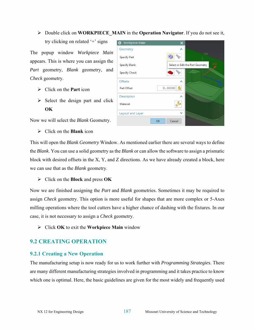
Double click on WORKPIECE_MAIN in the Operation Navigator. If you do not see it,
try clicking on related ‘+’ signs
The popup window Workpiece Main
appears. This is where you can assign the
Part geometry, Blank geometry, and
Check geometry.
Click on the Part icon
Select the design part and click
OK
Now we will select the Blank Geometry.
Click on the Blank icon
This will open the Blank Geometry Window. As mentioned earlier there are several ways to define
the Blank. You can use a solid geometry as the Blank or can allow the software to assign a prismatic
block with desired offsets in the X, Y, and Z directions. As we have already created a block, here
we can use that as the Blank geometry.
Click on the Block and press OK
Now we are finished assigning the Part and Blank geometries. Sometimes it may be required to
assign Check geometry. This option is more useful for shapes that are more complex or 5-Axes
milling operations where the tool cutters have a higher chance of dashing with the fixtures. In our
case, it is not necessary to assign a Check geometry.
Click OK to exit the Workpiece Main window
9.2 CREATING OPERATION
9.2.1 Creating a New Operation
The manufacturing setup is now ready for us to work further with Programming Strategies. There
are many different manufacturing strategies involved in programming and it takes practice to know
which one is optimal. Here, the basic guidelines are given for the most widely and frequently used

NX 12 for Engineering Design 188 Missouri University of Science and Technology
strategies. This chapter will also cover some important parameters that are to be set for the
programs to function properly.
Click on the Create Operation icon in the toolbar
The Create Operation window will pop up.
Make sure the Type of Operation is Mill_Contour
There are a set of different subtypes under Mill-Contour, namely Cavity Mill, Z-Level Follow
Cavity, Follow Core, Fixed Contour, and so on. These
different subtypes are used for different situations and
profiles of the design part. As mentioned before, how you
select a strategy for a certain situation depends on your
knowledge and experience.
Click on the Cavity_Mill icon at the top left as
shown in the figure
Choose the Program as 1234
Change the Geometry to WORKPIECE_MAIN
Click OK
The program parameters window with Cavity Mill in the
title bar will pop up. On this window, you can set all the
parameters for this program. A brief introduction on every
important parameter and terminology will be given as we
go through the sequence.
9.2.2 Tool Creation and Selection
One of the most important decisions to make is to select a tool with the right shape and size to use.
Before starting with the Tool parameter settings, we must first know about the types of Tool
cutters. The Milling Tool Cutters are categorized into three forms of cutters. Hence, when selecting
a cutter, it is important to take into consideration the size, shape, and profiles of the design parts.
For example, if the corner radius of a pocket is 5 mm, the pocket should be finished by a cutter

NX 12 for Engineering Design 189 Missouri University of Science and Technology
with a diameter less than or equal to 10 mm. Otherwise it will leave material at the corners. There
are other special forms of cutters available in markets that are manufactured to suit different needs.
Flat End Mill Cutters
These cutters have a sharp tip at the end of the cutter as shown in the figure below. These cutters
are used for finishing parts that have flat vertical walls with sharp edges at the intersection of the
floors and walls.
Ball End Mill
These cutters have the corner radii exactly equal to half the diameter of the shank. This forms the
ball shaped profile at the end. These cutters are used for roughing and finishing operations of parts
or surfaces with freeform features.
Bull Nose Cutters
These cutters have small corner radii and are widely used for roughing and/or semi-finishing the
parts as well as for finishing of inclined and tapered walls.
The cutter that we are going to use to rough out this huge volume is BUEM12X1 (Bullnose End
Mill with 12 diameter and 1 corner radius).
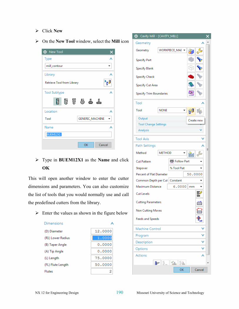
In the Cavity Mill popup menu click on the Create New button in the Tool dialog box
NX 12 for Engineering Design 190 Missouri University of Science and Technology
Click New
On the New Tool window, select the Mill icon
Type in BUEM12X1 as the Name and click
OK
This will open another window to enter the cutter
dimensions and parameters. You can also customize
the list of tools that you would normally use and call
the predefined cutters from the library.
Enter the values as shown in the figure below

NX 12 for Engineering Design 191 Missouri University of Science and Technology
Click OK
9.2.3 Tool Path Settings
Make sure that the Tool Axis is perpendicular to the top surface on the block.
Click on Tool Axis and choose Specify Vector
Select the appropriate axis as shown
In the Cavity Mill menu click on the Path
Settings option
There are different Cut Patterns in which the tool can
move. The following is a description of each.
Follow Part: This is the most optimal strategy where
the tool path is manipulated depending on the part geometry. If there are cores and cavities in the
part, the computer intelligently considers them to remove the materials in an optimal way. This is
widely used for roughing operations.
Follow Periphery: This takes the path depending
upon the periphery profile. For example, if the outer
periphery of our part is rectangular, the tool path will be
generated such that it gradually cuts the material from
outside to inside with a Stepover value. This option is
mostly used for projections and cores rather than cavities.
Profile: This takes the cut only along the profile of
the part geometry. It is used for semi-finishing or
finishing operations.
Trochoidal: This cutter is huge and is used for removing a large amount of material. The bulk
of material is removed by gradual trochoidal movements. The depth of cut used will be very high
for this strategy.
Zig: This takes a linear path in only one direction of flow.

NX 12 for Engineering Design 192 Missouri University of Science and Technology
Zig Zag: This tool takes a zigzag path at every level of depth. It saves time by reducing
amount of air cutting time (idle running). The climb and conventional cuts alternate.
Zig with Contour: This takes the path in one direction either climb or conventional. The
unique thing is that it moves along the contour shape nonlinearly.
For this exercise, select the Follow Part icon from the Cut Pattern drop-down menu since
we have both projections and cavities in the part
9.2.4 Step Over and Scallop Height
Step Over
This is the distance between the consecutive passes of milling. It can
be given as a fixed value or the value in terms of cutter diameter.
The Stepover should not be greater than the effective diameter of the
cutter, otherwise it will leave extra material at every level of cut and
result in an incomplete milling operation. The numeric value or
values required to define the Stepover will vary depending on the
Stepover option selected. These options include Constant, Scallop,
Tool Diameter, etc. For example, Constant requires you to enter a
distance value in the subsequent line.
Scallop Height
Scallop Height controls the distance between parallel passes according to the maximum height of
material (scallop) you specify to be left between passes. This is affected by the cutter definition
and the curvature of the surface. Scallop allows the system to determine the Stepover distance
based on the scallop height you enter.

NX 12 for Engineering Design 193 Missouri University of Science and Technology
For the Stepover, select %Tool Flat and change the Percent to 70
9.2.5 Depth Per Cut
This is the value to be given between levels to slice the geometry into layers and the tool path cuts
as per the geometry at every layer. The cut depth value can vary for each level. Levels are
horizontal planes parallel to the XY plane. If we do not give cut levels, the software will
unnecessarily try to calculate slices for the entire part and machine areas that are not in our interest.
Change the Common Depth per Cut value to 0.5
Now we will add the level ranges. This will split the part into different levels along the Z-direction
to be machined.
Click on Cut Levels
This will pop up a dialog box of Cut Levels. You need
to set the level of the cut. You can either point to the
object till which the cut level is or provide it as a
Range Depth value. We are not going to mill up to the
bottommost face of the part, but up to the floor at 40
mm from top. Therefore, we must delete the last level.
Change the Range Type to User Defined
Change the Range Depth to 80
Select OK
9.2.6 Cutting Parameters
On the Path Settings menu, click Cutting
Parameters
Under the Strategy tab button, change the Cut
Order from Level First to Depth First

NX 12 for Engineering Design 194 Missouri University of Science and Technology
Changing the cut order to Depth First orders the software to generate the tool path such that it will
mill one island completely up to the bottom-most depth before jumping to another island. The
Depth First strategy reduces the non-cutting time of the program due to unnecessary retracts and
engages at each depth of cut.
Click on the Stock tab
Change the value of the Part Side Stock to 0.5
This value is the allowance given to every side of the
part. If you want to give different values to the floors
(or the flat horizontal faces) uncheck the box next to
Use Floor Same As Side and enter a different value for
Part Floor Stock.
Click OK
9.2.7 Avoidance
Click the Non Cutting Moves
Click the Avoidance tab
This window consists of several avoidance points of
which we are concerned with the following points:
From Point
This is the point at which the tool change command
will be carried out. The value is normally 50 or 100
mm above the Z=0 level to enhance the safety of the
job when the cutter is changed by the Automatic Tool
Changer (ATC).
Click From Point
Choose Specify in the Point Option field
In the Point Dialog, enter the coordinates of
XC, YC and ZC as (0, 0, 50)

NX 12 for Engineering Design 195 Missouri University of Science and Technology
Click OK
Start Point
This is the point at which the program starts and ends. This value is also 50 or 100 mm above the
Z=0 level to enhance safety. It is also the point at which the machine operator checks the height of
the tool mounted on the spindle with respect to the Z=0 level from the job. This cross checks the
tool offset entered in the machine.
Click on Start Point
Choose Specify
Enter the coordinates (0, 0, 50) in the Point Dialog
Click OK to exit the Point Constructor
Clearance Plane is the plane on which the tool cutter will retract before moving to the next region
or island. This is also known as Retract Plane. Sometimes the Clearance Plane can be the previous
cutting plane. However, when the tool has to move from one region to another, it is necessary to
move to the Clearance Plane before doing so. The value of the Clearance Plane should be at least
2 mm above the topmost point of the workpiece or fixture or whichever is fixed to the machine
bed.
Click on the Transfer/Rapid tab
Choose Plane in the Clearance Option
Choose the XC-YC Plane from the drop-
down menu in Type tab
Under the Offset and Reference tab enter the
value of 3 as the Distance
Click OK twice to go back to the Cavity Mill
parameters window
9.2.8 Speeds and Feeds
Choose Feeds and Speeds to enter the feed and speed parameters
Speed

NX 12 for Engineering Design 196 Missouri University of Science and Technology
Speed normally specifies the revolutions per minute (rpm) of the spindle (spindle speed). However,
technically the speed refers to the cutting speed of the tool (surface speed). It is the linear velocity
of the cutting tip of the cutter. The relative parameters affecting this linear speed are rpm of the
spindle and the diameter of the cutter (effective diameter).
Enter the Spindle Speed value as 4500 rpm
For the Surface Speed and the Feed per Tooth, you should enter the recommended values given
by the manufacturers of the cutter (for this example, click on the calculator button near spindle
speed). By entering these values, the software will automatically calculate the cutting feed rate and
spindle speed. You can also enter your own values for feed rates and spindle speeds.
Feeds
There are many feeds involved in a single program.
The most important is the Cutting feed. This is the
feed at which, the tool will be in engagement with the
raw work-piece and actually cutting the material off
the work-piece. It is the relative linear velocity, at
which the cutter moves with respect to the job.
The other feeds are optional. Some machine control
systems use their default retracts and traverse feed. In
those cases, even if you do not enter the values of
other feeds, there would not be any problems. Some
control systems may look for these feed rates from the
program. It can be slightly less than the machine’s
maximum feed rate.
Enter the Cut value as 1200 mmpm
Click OK

NX 12 for Engineering Design 197 Missouri University of Science and Technology
9.3 PROGRAM GENERATION AND VERIFICATION
9.3.1 Generating Program
Now we are done entering all the parameters required
for the roughing program. It is time to generate the
program.
Click on the Generate icon at the bottom of the
window
You can now observe the software slicing the model
into depths of cuts and creating tool-path at every level.
You can find on the model cyan, blue, red and yellow
lines as shown in the figure.
9.3.2 Tool Path Display
Whenever you want to view the entire tool-path of the
program, right-click on the program in Operation
Navigator and click Replay. It will give the display as
shown in the Figure below.

NX 12 for Engineering Design 198 Missouri University of Science and Technology
You can now observe that next to the program in the Operation Navigator is a yellow exclamation
point instead of a red mark. This means that program has been generated successfully but has not
been post-processed. If any change is made in the model, the program will again have a red mark
next to it. This implies that the program has to be generated again. However, there is no need to
change any parameters in the program.
9.3.3 Tool Path Simulation
It is very important to check the programs you have created. This prevents any improper and
dangerous motions from being made in the cutting path. It is possible that wrong parameters and
settings will be given that cause costly damages to the work piece. To avoid such mistakes, NX 12
provides a Tool-path verification and a Gouge check.
The Tool-Path verification can be used to view the cutter motion in the entire program. You can
observe how the tool is engaged and how it retracts after cutting. It also shows the actual material
being removed through graphical simulation. You can also view the specific zone of interest by
moving the line of the program.
Right-click on the program in the Operation Navigator and choose Tool Path → Verify
or click on the Verify Tool Path button in the toolbar
This will allow you to set the parameters for visualization of the Tool-Path.
NX 12 for Engineering Design 199 Missouri University of Science and Technology
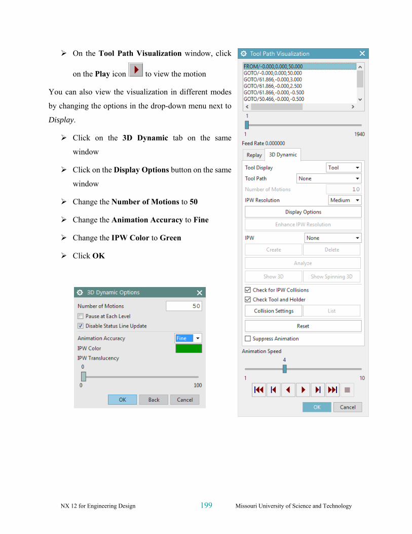
On the Tool Path Visualization window, click
on the Play icon to view the motion
You can also view the visualization in different modes
by changing the options in the drop-down menu next to
Display.
Click on the 3D Dynamic tab on the same
window
Click on the Display Options button on the same
window
Change the Number of Motions to 50
Change the Animation Accuracy to Fine
Change the IPW Color to Green
Click OK

NX 12 for Engineering Design 200 Missouri University of Science and Technology
Click on the Play button again
The simulation will look as shown in the figure on
the right. With this option, you will be able to view
the actual cutting simulation and material removal
through computer graphics. It is 3D Dynamic, where
you can rotate, pan and zoom the simulation when it
is playing.
9.3.4 Gouge Check
Gouge Check is used to verify whether the tool is removing any excess material from the work-
piece with respect to Part Geometry. Considering a Design Tolerance, any manufacturing process
may produce defective parts by two ways. One is removing excess material, which is also called
Less Material Condition. The other one is leaving materials that are supposed to be removed which
is More Material Condition. In most cases, the former is more dangerous since it is impossible to
rework the design part. The latter is safer since the leftover material can be removed by reworking
the part. The gouge check option checks for the
former case where the excess removal of material
will be identified.
Right Click the program in the Operation
Navigator
Choose Tool Path → Gouge Check
Click OK
After the gouge check is completed, a Tool Path
Report window will pop up. If in case there are any
gouges found, it is necessary to correct the program.
Otherwise,
Click OK or directly close the popup window

NX 12 for Engineering Design 201 Missouri University of Science and Technology
9.4 OPERATION METHODS
9.4.1 Roughing
In case of milling operation, the first operation should be rough milling before finishing the job.
The main purpose of roughing is to remove bulk material at a faster rate, without affecting the
accuracy and finish of the job. Stock allowances are given to provide enough material for the
finishing operation to get an accurate and good finish job. What we did in the previous part of this
chapter is generating a roughing program. Now we have to moderately remove all the uneven
material left over from the previous program.
9.4.2 Semi-Finishing
Semi-Finishing programs are intended to remove the unevenness due to the roughing operation
and keep even part stock allowance for the Finishing operations. Once we are done with the first
roughing program, semi-finishing is always easier and simpler to perform.
Now we will copy and paste the first program in the Operation Navigator. In the new program,
you only have to change a few parameters and cutting tool dimensions and just regenerate the
program.
Right click CAVITY_MILL program in the
Operation Navigator and click Copy
Right-click CAVITY_MILL again and
choose Paste
Right-click the second
CAVITY_MILL_COPY you just made and click Rename
Rename the second program as CAVITY_MILL_1
You can see that next to the newly created CAVITY_MILL_1 is a red mark, which indicates that
the program is not generated.
Let us now set the parameters that need to be changed for the second program. Before we start, we
should analyze the part geometry to figure out the minimum corner radius for the cutter diameter.
In our model, it is 5 mm and at the floor edges, it is 1 mm. Therefore, the cutter diameter can be

NX 12 for Engineering Design 202 Missouri University of Science and Technology
anything less than 10 mm. For optimal output and rigidity, we will choose a Bull Nose Cutter with
a diameter of 10 and a lower radius of 1.
Double click CAVITY_MILL_1 on Operation Navigator to open the parameters
window
Just as we did in the previous program, we will create a new cutter. In the Tool tab, you will see
the cutter you first chose. It will show BUEM12X1 as the current tool.
Create a new Mill and name it BUEM10X1
It should have a Diameter of 10, a Lower
Radius of 1 and a Flute Length of 38
Click OK
Click the Common Depth per Cut as 0.25 in
the Path Settings
Then click on Cutting Parameters button
Click on the Stock tab
Uncheck the box next to Use Floor Same As
Side
Enter 0.25 for Part Side Stock
Enter 0.1 for Part Floor Stock
Click on the Containment tab button
NX 12 for Engineering Design 203 Missouri University of Science and Technology
In the drop-down menu next to In Process Workpiece, choose Use 3D
In Process Workpiece is a very useful option in NX. The software considers the previous program
and generates the current program such that there is no unnecessary cutting motion in the No-
material zone. This strategy reduces the cutting time and air cutting motion drastically. The
algorithm will force the cutter to only remove that material, which is left from the previous
program and maintain the current part stock allowance.
Choose OK to return to the Parameters window
Click Feeds and Speeds
Enter the Spindle Speed as 5000
Then click OK
The parameters and settings are finished for the semi-finishing program.
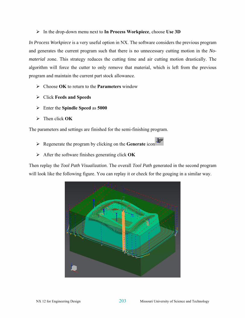
Regenerate the program by clicking on the Generate icon
After the software finishes generating click OK
Then replay the Tool Path Visualization. The overall Tool Path generated in the second program
will look like the following figure. You can replay it or check for the gouging in a similar way.

NX 12 for Engineering Design 204 Missouri University of Science and Technology
9.4.3 Finishing Profile
So far, we are done with the roughing and semi-finishing programs for the part. There is a small
amount of material left in the Workpiece to be removed in the finishing programs to obtain the
desired accurate part geometry. The finishing programs should be generated such that every
surface in the part should be properly machined. Therefore, it is better to create more than one
program to uniquely machine sets of surfaces with relevant cutting parameters and strategies rather
than make one program for all the surfaces. The following illustrates how to group the profiles and
surfaces and create the finishing programs.
9.4.3.1 Outer Profile
This program is intended to finish the outer inclined walls onto the bottom of the floor. Because
the program should not touch the contour surface on the top, we will give Check and Trim
boundaries in the program.
Repeat the same procedure as before to copy and paste CAVITY_MILL_1 on Operation
Navigator
Rename the program CAVITY_MILL_2
Double click CAVITY_MILL_2 to make parameter changes
In the popup parameters window, change the Cut Pattern to Profile and the Stepover
percentage to 40
Click on the Specify Trim Boundaries tab
The Trim Boundaries window will pop up. Make sure
to carry out the following procedure in the right
sequence. Keep the default setting of Trim Side to
Inside. This tells the software that the cutter should not
cut material anywhere inside the boundary. Trim allows
you to specify boundaries that will further constrain the cut regions at each cut level.
Change the Selection Method to Curves
Change the Plane from Automatic to Specify and click on the Plane Dialog

NX 12 for Engineering Design 205 Missouri University of Science and Technology
A new window will pop up. The window will ask for the mode of selection of the plane on which
the curves should be projected. This should normally be over the topmost point of the part
geometry. Precisely, it should be over the MCS.
Choose the XC-YC Plane from the drop-down menu under Type
Enter a value of 3 next to Distance
Click OK
Now we will start selecting edges from the part. These selected edges will be projected on the Z =
3 plane as curves and used as the boundary.
Select all the top outer edges on the wall along the contour surface as shown in the figure.
Make sure to select all 8 edges and in a continuous order
Choose OK
Enter the Common Depth per Cut as 0.2
Click Cutting Parameters
In the popup dialog box, click on Stock tab
Enter the Part Side Stock and Part Floor Stock values to be 0.00

NX 12 for Engineering Design 206 Missouri University of Science and Technology
Intol allows you to specify the maximum distance that a
cutter can deviate from the intended path into the
workpiece.
Outtol allows you to specify the maximum distance that
a cutter can deviate from the intended path away from the
workpiece.
Enter the Intol and Outtol values to be 0.001 as
shown in the figure
Click OK
Click on the Generate icon to generate the
program in the Main Parameters window
Click OK on the parameters window when the
program generation is completed
The finishing program for the outer profile is now ready. You can observe while replaying the tool
path that the cutter never crosses the boundary that has been given for trim and check. The cutter
retracts to the Z=3 plane for relocation.

NX 12 for Engineering Design 207 Missouri University of Science and Technology
9.4.3.2 Inner profile
Repeat the same procedure as before to copy and paste CAVITY_MILL_2 on Operation
Navigator and rename it as CAVITY_MILL_3
Double click CAVITY_MILL_3 to edit the parameters or right click on it and choose Edit
Select the Specify Trim Boundaries tab and choose Trim Side to be Outside in the popup
dialog box
This will prevent the cutter from passing outside the boundary.
Change Selection Method to Curves
Change the plane manually to be the XC-YC plane and enter the offset distance as 3
Click OK
Select all the top inner edges along the contour surface as shown in the figure. Again, make
sure all 8 edges are selected in a continuous order (using Shift+click to de-select a curve).
Choose OK to return to the parameters window
Generate the program
Click OK when the generation is finished
The finishing program for the inner profile is now ready. By replaying the tool path, you can
observe that the cutter never crosses the boundary that has been given for trim and check.

NX 12 for Engineering Design 208 Missouri University of Science and Technology
9.4.4 Finishing Contour Surface
Now we will use a different type of strategy to finish the top freeform surface.
Click on the Create Operation icon in the Toolbar
Click on the Fixed Contour icon as
shown in the figure
Choose 1234 for Program
Choose WORKPIECE_MAIN for
Geometry
Keep the default name of program
Click OK
On the Parameters window, under Drive Method, make sure that Boundary is selected

NX 12 for Engineering Design 209 Missouri University of Science and Technology
Click icon, which will pop up the Boundary Drive Method window, click on the
icon as shown in the figure to open the Boundary Geometry menu
Change the Mode to Curves/Edges
Select the Material Side to be Outside
Select the Tool Position to be On
The Tool Position determines how the tool will position itself when it approaches the Boundary
Member. Boundary Members may be assigned one of three tool positions: On, Tanto, or Contact.
In On position, the center point of the tool aligns with the boundary along the tool axis or
projection vector.
In Tanto position, the side of the tool aligns with the boundary.
In Contact position, the tool contacts the boundary.
For the Plane, choose User-Defined
Again, set the plane to be XC-YC with a Distance of 3
Click OK
Select the outer loop of the top contour surface as shown in the figure. Remember to select
the edges in a continuous order

NX 12 for Engineering Design 210 Missouri University of Science and Technology
Click OK
We have trimmed the geometry outside the loop. Now we have to trim the geometry inside the
inner loop so that the only geometry left will be the area between the two loops.
Choose the Mode to be Curves/Edges
Choose the Material Side to be Inside and Tool Position to be On
Choose the plane to be user-defined at XC-YC with a Distance of 3
Select the inner edges of the contour surface as shown
Click OK to return to the Boundary Drive Method window
Change the Stepover method to Scallop and enter the height to be 0.001 and click OK

NX 12 for Engineering Design 211 Missouri University of Science and Technology
Click on Cutting Parameters
Change the Tolerance values in the Stock tab so
that the Part Intol and Part Outtol is 0.001
Click on the More tab button and enter the value
of Max Step as 1.0
Click OK
In the main parameters window,
Create a new tool and name it BEM10
Change the diameter to be 10 mm and the lower
radius to be 5 mm.
Click OK
Click on the Feeds and Speeds icon on the
parameters window
Enter the Spindle Speed, Feed Rates (Cut) and
calculate the others as shown in the figure on
right
Click OK
Generate the program
The contour surface is now finished and you can view the
simulation by Tool Path Verification.

NX 12 for Engineering Design 212 Missouri University of Science and Technology
9.4.5 Flooring
Flooring is the finishing operation performed on the
horizontal flat surfaces (Floors) of the part. In most of
the milling processes, flooring will be the final
operation of them. All the horizontal surfaces will be
finished. This planar operation runs the cutter in a
single pass on every face.
Click on the Create Operation icon
Change the Type to be mill_planar at the top
of the window
Change all the options as shown in the figure
Click OK
In the parameters window, change the Cut
Pattern to be Follow Part

NX 12 for Engineering Design 213 Missouri University of Science and Technology
Change the percent of the tool diameter for
Stepover to be 40
In flooring operations, it is always better to keep the
Stepover value to be less than half of the diameter of the
cutter in order to achieve more flatness on the planar
surfaces.
Unlike previous programs, we have to select a cut area.
Click on the Specify Cut Area Floor as shown
Select the highlighted surfaces shown in the
figure below
In case you are not able to select the surfaces as shown
go to Part Navigator and Hide the Blank (to choose the
blank, you can right click on the blank, use Select from
List…), select the surfaces and Unhide the Blank again.
Click OK
Click on Cutting Parameters in the main parameter window
Choose the Stock tab button and enter the Intol and Outtol values as 0.001
Click OK
Click on Feeds And Speeds

NX 12 for Engineering Design 214 Missouri University of Science and Technology
In the main Parameters window,
Create a new tool and name it BEF105
Change the diameter to be 10 mm and the lower
radius to be 5 mm
Click OK
Because this is a Flooring operation, it is better to make
the spindle speed high and the feed rates low compared
to the previous operations.
Enter the values for Spindle Speed, Feed Rates
(Cut) and calculate the others as shown in the
figure
Choose OK
Generate the program. Then replay and verify
the cutter path
The following figure shows the Tool Path display for the flooring.

NX 12 for Engineering Design 215 Missouri University of Science and Technology
9.5 POST PROCESSING
The primary use of the Manufacturing Application is to generate tool paths for manufacturing
parts. Generally, we cannot just send an unmodified tool path file to a machine and start cutting
because there are many different types of machines. Each type of machine has unique hardware
capabilities, requirements and control systems. For instance, the machine may have a vertical or a
horizontal spindle; it can cut while moving several axes simultaneously, etc. The controller accepts
a tool path file and directs tool motion and other machine activity (such as turning the coolant or
air on and off).
Naturally, as each type of machine has unique hardware characteristics; controllers also differ in
software characteristics. For example, most controllers require that the instruction for turning the
coolant on be given in a particular code. Some controllers also restrict the number of M codes that
are allowed in one line of output. This kind of information is not in the initial NX tool path.
Therefore, the tool path must be modified to suit the unique parameters of each different
machine/controller combination. The modification process is called Post Processing. The result is
a Post Processed tool path.
There are two steps involved in generating the final post-processed tool path.
1. Create the tool path data file, or called CLSF (Cutter Location Source File).
2. Post process the CLSF into machine CNC code (Post Processed file). This program reads
the tool path data and reformats it for use with a particular machine and its accompanying
controller.

NX 12 for Engineering Design 216 Missouri University of Science and Technology
9.5.1 Creating CLSF
After an operation is generated and saved, the resulting tool path is stored as part of the operation
within the part file. CLSF (Cutter Location Source File) provides methods to copy these internal
paths from the operations in the part file to tool paths within the CLSF, which is a text file. The
GOTO values are a "snapshot" of the current tool path. The values exported are referenced from
the MCS stored in the operation. The CLS file is the required input for some subsequent programs,
such as postprocessors.
Click on one of the programs that
you want to post process in the
Operation Navigator
Click on Output CLSF in the
Operations toolbar
A window will pop up to select the CLSF
Format.
Choose CLSF_STANDARD and
enter a location for the file
Choose OK
The CLSF file will be created. It will be similar to the figure
below. The contents of the file contain the basic code of the cutter
motion without any information about machine codes and control
systems. This file can be used for post-processing any machine
control. The extension of the file is .cls.

NX 12 for Engineering Design 217 Missouri University of Science and Technology
Any program that has been output to CLSF or Post Processed will have a green checkmark next
to it in the Operation Navigator.
9.5.2 Post Processing
Click on a program in the Operation Navigator that you want to post process
Click Menu → Tools → Operation
Navigator →Output →Postprocess or
from the Home tab as shown
Select the MILL_3_AXIS machine and enter a location for the file
Select OK
This will create the Post Processed file for the target machine. You can find the block numbers
with G and M codes concerning the machine controller type. The extension of the file is .ptp.

NX 12 for Engineering Design 218 Missouri University of Science and Technology
The final output (filename.ptp) file can be transferred to a machine for conducting an actual milling
operation. The entire sequence starting from the transfer of the model into the Manufacturing
module to the transfer of the files to the machine and fabricating the raw piece into the final part
is called Computer Aided Manufacturing.


