Chapter 8 Slot Antennas - eetrend.com · 8-2 CHAPTER EIGHT 8.1 INTRODUCTION ... the slot antenna is...
16
8-1 Slot Antennas William F. Croswell Harris Corporation CONTENTS 8.1 INTRODUCTION. . . . . . . . . . . . . . . . . . . . . . . . . . . . . . . . . . . . . . . . . . 8-2 8.2 SLOTTED-WAVEGUIDE ANTENNAS . . . . . . . . . . . . . . . . . . . . . . . . . 8-2 8.3 TAPERED AND FLARED SLOT ANTENNAS . . . . . . . . . . . . . . . . . . . . 8-4 8.4 CAVITY-BACKED RECTANGULAR SLOT ANTENNAS . . . . . . . . . . . . 8-5 8.5 WAVEGUIDE-FED SLOT ANTENNAS . . . . . . . . . . . . . . . . . . . . . . . . . 8-8 8.6 SLOT ANTENNAS ON FINITE AND CURVED GROUND PLANES . . . . . . . . . . . . . . . . . . . . . . . . . . . . . . . . . . . . . . . 8-10 8.7 SLOT ANTENNAS ON CYLINDERS, CONES, AND SPHERES. . . . . . 8-14 Chapter 8 Downloaded from Digital Engineering Library @ McGraw-Hill (www.digitalengineeringlibrary.com) Copyright © 2007 The McGraw-Hill Companies. All rights reserved. Any use is subject to the Terms of Use as given at the website. Source: ANTENNA ENGINEERING HANDBOOK
Transcript of Chapter 8 Slot Antennas - eetrend.com · 8-2 CHAPTER EIGHT 8.1 INTRODUCTION ... the slot antenna is...

8-1
Slot Antennas
William F. CroswellHarris Corporation
CONTENTS
8.1 INTRODUCTION. . . . . . . . . . . . . . . . . . . . . . . . . . . . . . . . . . . . . . . . . . 8-2
8.2 SLOTTED-WAVEGUIDE ANTENNAS . . . . . . . . . . . . . . . . . . . . . . . . . 8-2
8.3 TAPERED AND FLARED SLOT ANTENNAS . . . . . . . . . . . . . . . . . . . . 8-4
8.4 CAVITY-BACKED RECTANGULAR SLOT ANTENNAS . . . . . . . . . . . . 8-5
8.5 WAVEGUIDE-FED SLOT ANTENNAS . . . . . . . . . . . . . . . . . . . . . . . . . 8-8
8.6 SLOT ANTENNAS ON FINITE AND CURVED GROUND PLANES . . . . . . . . . . . . . . . . . . . . . . . . . . . . . . . . . . . . . . . 8-10
8.7 SLOT ANTENNAS ON CYLINDERS, CONES, AND SPHERES. . . . . . 8-14
Chapter 8
Downloaded from Digital Engineering Library @ McGraw-Hill (www.digitalengineeringlibrary.com)Copyright © 2007 The McGraw-Hill Companies. All rights reserved.
Any use is subject to the Terms of Use as given at the website.
Source: ANTENNA ENGINEERING HANDBOOK

8-2 CHAPTER EIGHT
8.1 INTRODUCTION
This chapter deals with the radiation characteris-tics of slot antennas and includes the effects of finite and curved surfaces, dielectric coatings, cavity backing, and single slots fed by wave-guides. The simplest example of such an antenna consists of a rectangular slot cut in an extended thin flat sheet of metal with the slot free to radiate on both sides of this sheet, as shown in Figure 8-1. The slot is excited by a voltage source such as a balanced parallel transmission line connected to the opposite edges of the slot or a coaxial trans-mission line connected to the opposite edges of the slot or a coaxial transmission line.
The electric field distribution in the slot can be obtained from the relationship between the slot and complementary wire antennas, as established by Booker.1 It has been shown that the electric field distribution (magnetic current) in the slot is identical to the electric current distribution on the complementary wire. In the illustrated rectangular slot, the electric field is perpendicular to the long dimension, and its amplitude vanishes at the ends of the slot.
The electric field is everywhere normal to the surface of the slot antenna except in the region of the slot itself. The theoretical analysis of this configuration shows that the radiation of the currents in the sheet can be deduced directly from the distribution of the electric field in the slot. Consequently, the radiated field of an elementary magnetic moment within the slot boundaries should include the contribution of the electric current flowing on a metal surface.
A slot-antenna design will often require that the slot be cut in something other than an extended flat sheet surface. Whatever the surface, the electric field will be normal every-where except in the region of the slot. The field due to the electric currents on this metal surface can be deduced from the exciting magnetic currents2 in the slot, just as in the case of the flat metal sheet. This field can be combined with the exciting field so that the result is the total field due to a magnetic current on the given boundary surface. Thus the field of a thin rectangular slot cut in a circular cylinder differs from that of a slot cut in a flat metal sheet because the distribution of electric currents is different for the two cases.
In general, the slot antenna is not free to radiate on both sides of the surface on which it is cut because one side is either completely enclosed, e.g., the slotted cylinder antenna, or it is desired that the radiation on one side be minimized. In these cases, the influence of the enclosed cavity region on the excitation and impedance of the slot antenna is significant to the antenna design.
8.2 SLOTTED-WAVEGUIDE ANTENNAS
Slotted-waveguide antennas have significant applications in the areas of missile, spacecraft, and airborne radar. Broad-wall slotted-waveguide antennas have been studied extensively. Oliner,3 following research by Stevenson,4 has derived equivalent circuit representations for this type of antenna. These circuits allow accurate computation of the normalized con-ductance, susceptance, resistance, reactance, and resonant frequency of broad-wall slots. The types of slots and the equivalent networks are given in Chapter 9.
Dielectric-covered broad-wall slots also have been characterized thoroughly. Bailey5 has summarized significant findings. The general problem discussed by Bailey extends Oliner’s work to include the effects on broad-wall slots radiating into a multilayer dielectric medium. The basic effect that occurs by adding a dielectric layer over slots in a waveguide is to
FIGURE 8-1 Rectangular slot
Downloaded from Digital Engineering Library @ McGraw-Hill (www.digitalengineeringlibrary.com)Copyright © 2007 The McGraw-Hill Companies. All rights reserved.
Any use is subject to the Terms of Use as given at the website.
Slot Antennas

SLOT ANTENNAS 8-3
produce a downward shift in resonant frequency. For dielectric layers whose thickness is greater than 0.2l, where λ λ ε= 0 , the approximate resonant shift is given in Figure 8-2, where l is the wavelength in the dielectric, l0 is the wavelength in free space, and e is the dielectric constant. Further analysis, and comparison with experimental data, is also avail-able, as shown in Figure 8-3.
FIGURE 8-2 Resonant length of a dielectric-covered shunt slot in WR-90 (RG 52/U) wave-guide (b1 = 0.0625 in, t = 0.050 in, a = 0.900 in, b = 0.400 in) (after Bailey5 © IEEE 1970)
FIGURE 8-3 Resonant conductance (a) and resonant length (b) versus layer thickness, er = 3.31 (after Katehi6 © IEEE 1990)
Downloaded from Digital Engineering Library @ McGraw-Hill (www.digitalengineeringlibrary.com)Copyright © 2007 The McGraw-Hill Companies. All rights reserved.
Any use is subject to the Terms of Use as given at the website.
Slot Antennas
8-4 CHAPTER EIGHT
The typical polarization of most slotted-waveguide antennas is linear. However, several slotted-waveguide elements have been designed that produce circular polarization.7,8
8.3 TAPERED AND FLARED SLOT ANTENNAS
Tapered slot antennas (TSAs) were first introduced in the late 1950s. It was then that Eberle et al9 produced a waveguide-fed, flared slot antenna for use in aircraft skins where conventional antennas could not be easily integrated. Gibson10 then developed the strip-line-fed, exponentially tapered slot antenna, which he called the Vivaldi aerial. His design was the first recognized TSA that showed symmetric E- and H-plane beamwidths, low sidelobes, and moderate gain.
Since then, with the increased interest in MIC (microwave integrated circuit) anten-nas for applications ranging from satellite communications to remote sensing, tapered slot antennas have been studied extensively, both empirically and theoretically. In general, the performance you can expect to achieve from a typical TSA includes
Broadband operation Moderate gain Low sidelobes
These radiation characteristics make TSAs suitable elements for reflector feeds or as stand-alone antennas.
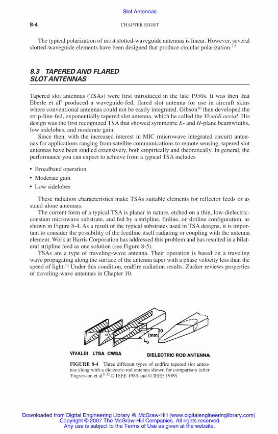
The current form of a typical TSA is planar in nature, etched on a thin, low-dielectric-constant microwave substrate, and fed by a stripline, finline, or slotline configuration, as shown in Figure 8-4. As a result of the typical substrates used in TSA designs, it is impor-tant to consider the possibility of the feedline itself radiating or coupling with the antenna element. Work at Harris Corporation has addressed this problem and has resulted in a bilat-eral stripline feed as one solution (see Figure 8-5).
TSAs are a type of traveling-wave antenna. Their operation is based on a traveling wave propagating along the surface of the antenna taper with a phase velocity less than the speed of light.13 Under this condition, endfire radiation results. Zucker reviews properties of traveling-wave antennas in Chapter 10.
FIGURE 8-4 Three different types of endfire tapered slot anten-nas along with a dielectric-rod antenna shown for comparison (after Yngvesson et al11,12 © IEEE 1985 and © IEEE 1989)
Downloaded from Digital Engineering Library @ McGraw-Hill (www.digitalengineeringlibrary.com)Copyright © 2007 The McGraw-Hill Companies. All rights reserved.
Any use is subject to the Terms of Use as given at the website.
Slot Antennas

SLOT ANTENNAS 8-5
8.4 CAVITY-BACKED RECTANGULAR SLOT ANTENNAS
The electric field on the coaxially fed, cavity-backed rectangular slot (see Figure 8-6a) is neither sinusoidal nor complementary to a ribbon dipole antenna. This antenna is a cav-ity resonator, energized by the coaxial transducer, which radiates from the slot aperture. The field distribution in the slot, therefore, is dependent on the excitation of higher cavity modes as well as the principal mode (TE10). The equivalent circuit of a cavity-backed slot antenna is shown in Figure 8-7b; the shunt conductance is the radiation conductance of the slot. The conductance of the cavity-backed resonant half-wave slot is half the open slot, free to radiate on both sides. That is, the shunt resistance is at least 800 rather than 400 Ω.14–16 The parallel susceptance shown in the equivalent circuit is the sum of the shunt susceptance of the slot radiator and the TE-mode susceptance of the cavity. The series-resonant circuit is the result of the energy stored in the TM modes in the cavity and feed structure.
FIGURE 8-5 Stripline designs of the bilateral slotline-fed antenna. Note 1: Length of taper is proportional to gain; maximum gain approximately 10 dB. Note 2: Quarter wave calculated using dielectric constant of material. Note 3: May be narrower than 0.4 to obtain desired slotline imped-ance. Taper rate: y = akx, where a = 0.5 slotline width, k = constant, x = length of flare.
FIGURE 8-6 Cavity-backed rectangular slot: (a) pictorial representation; (b) equivalent circuit
Downloaded from Digital Engineering Library @ McGraw-Hill (www.digitalengineeringlibrary.com)Copyright © 2007 The McGraw-Hill Companies. All rights reserved.
Any use is subject to the Terms of Use as given at the website.
Slot Antennas

8-6 CHAPTER EIGHT
To obtain the maximum radiation conductance, a sinusoidal distribution of electric field (magnetic current) must be generated. This distribution will be achieved when the energy stored in the cavity in the vicinity of the slot is primarily in the TE10 mode, i.e., by making the cavity dimensions big enough so that the dominant mode is above cutoff. For small cavities, edge loading, as in a highly capacitive slot, will improve the field distribution.
An important design parameter is the antenna Q, which is minimum when the stored energy is only in the dominant mode. The Q limits the inverse voltage-standing-wave-ratio (VSWR) bandwidth product; for a small cavity, it is
QV
>
34
12π
where V is the volume of the cavity expressed in cubic free-space wavelengths. This mini-mum Q is realized when the series reactance is eliminated through efficient feed and cavity design. For the simple capacitive slot-loaded cavity shown in Figure 8-6a, higher TE and TM modes will be generated with attendant high Q.
A broadband cavity-backed antenna can be realized by using a T-bar feed,17 as shown in Figure 8-7. A flat T-bar instead of the illustrated circular cross section will generate the same impedance if its width is equal to the diameter D.
The nominal input impedance to the T-bar is 125 Ω (approximate). To achieve the avail-able bandwidth, a broadband impedance transformer is needed between the 50-Ω coaxial transmission line and the T-bar junction.
The dimensions for a broadband flat T-bar covering the frequency range 0.5 to 1.2 GHz are shown in the diagram of Figure 8-7. The VSWR does not exceed 3:1 in the frequency band and is less than 2:1 over 90 percent of the band.
FIGURE 8-7 Cavity-backed T-bar-fed slot antenna. Typical dimensions shown in inches (millimeters) for a frequency range of 0.5 to 1.2 GHz: a, 12.00 (304.8); b, 4.00 (101.6); x, 3.25 (82.55); w, 6.75 (171.45); D, 2.25 (57.15); E, 0.75 (19.05); F, 0.63 (16.00); G, 0.19 (5.826); H, 0.25 (6.35).
Downloaded from Digital Engineering Library @ McGraw-Hill (www.digitalengineeringlibrary.com)Copyright © 2007 The McGraw-Hill Companies. All rights reserved.
Any use is subject to the Terms of Use as given at the website.
Slot Antennas

SLOT ANTENNAS 8-7
The resonant frequency can be modified by use of dielectric or ferrite loading within the cavity.18 The reduction in cavity volume and aperture size results in increased Q, smaller bandwidth, and lower efficiency.
A shallow ridged-cavity crossed-slot antenna19 has been developed for wide-angle cover-age in the ultrahigh-frequency range. The VSWR is dependent on the slot width, slot length, and cavity depth at the low end of the band. The ridge parameters tune the antenna in the midband and high-band frequencies. The VSWR is less than 2.7:1 from 240 to 279 MHz and under 2.1:1 from 290 to 400 MHz for cavity dimensions of 33 by 33 by 4 in.
An experimental square cavity-slot antenna (half scale) with crossed slots cut along the diagonal dimensions of the cavity is shown in Figure 8-8. The cavity configuration, ridges, and crossed-slot arrangement are illustrated. The slots are excited by four symmetrically located feed probes near the center of the cavity. Each opposite pair is connected to a wideband 180° hybrid. For circular polarization, the input ports of the two 180° hybrids are connected to a wideband 90° hybrid. The 3-dB beamwidth varies from 120° at the low end of the band to about 40° at the high end.
An earlier narrowband crossed-slot antenna was developed with a cavity depth of 2 in.20 A stripline version of the cavity-backed slot antenna has been designed.21 This design was used for many years as a low-profile antenna for rocket payloads.
FIGURE 8-8 Cavity-slot configuration with circular polarization of a ridged-cavity crossed-slot antenna. Typical dimensions shown in inches (millimeters) for a frequency range of 480 to 800 MHz: a, 16.00 (406.4); d, 2.00 (50.8); b, 1.25 (31.75); W1, 2.50 (73.5); W2, 0.65 (16.51); h1, 1.50 (38.1); h2, 1.75 (44.45); L, 22 (558.8).
Downloaded from Digital Engineering Library @ McGraw-Hill (www.digitalengineeringlibrary.com)Copyright © 2007 The McGraw-Hill Companies. All rights reserved.
Any use is subject to the Terms of Use as given at the website.
Slot Antennas

8-8 CHAPTER EIGHT
8.5 WAVEGUIDE-FED SLOT ANTENNAS
The waveguide opening onto a ground plane is commonly used in phased arrays and as a single element on curved as well as flat ground. An early analysis and experiment22 has been used extensively for checking various analytical methods. This early work has been extended to include a dielectric medium outside the slot,23 as shown in Figure 8-9. Also given in Figure 8-9 are calculations and measurements that agree with those in Cohen et al.22 It is noted in Croswell et al23 that substantial energy is coupled into the dielectric slab in the form of surface waves. Another extension of this work includes dielectric plugs flush-mounted to the ground plane just inside the waveguide.24 Dielectric plugs are very useful, but you must be careful of certain dielectric constants and plug thicknesses that can gener-ate very significant higher-order aperture modes.
Similar analysis has been performed for circular waveguides.25 The basic admittance of a typical TE11-mode excited slot is given in Figure 8-10. This TE11 excitation mode tends to couple less energy into the dielectric slab in the form of a surface wave. Hence the circu-lar waveguide antenna was used in many early rocket reentry payload designs employing dielectric ablation materials.
The radiation characteristics of any annular slot (cut in an infinite ground screen) are identical with those of a complementary wire loop with electric and magnetic fields inter-changed. In the case of the small slot, the radiation diagram is close to that of a small electric stub in the ground screen.
Consider a thin annular slot as shown in Figure 8-11. The polar axis of a spherical coordinate system being normal to the plane of the slot, the magnetic component of the radiated field is
HaVe
re dφ
θ φ φπλ φ φ= − ′−
− ′jkr
jka
120cos( ) sin cos( ) ′′∫ φ
π
0
2
where a = radius of slot V = voltage across slot K = 2p/l
For small values of a, that is, a < l/2p,
H jVe
rA
φ λ θ=− jkr
A/m60 2 sin
where A = pa2 is the included area of the annular slot. The previous equation is valid for small slots of arbitrary shape.
FIGURE 8-9 (a) Rectangular waveguide in a ground plane covered by a dielectric slab; (b) Effect of ground-plane size on the free-space admittance (after Croswell et al23 © IEEE 1967)
Downloaded from Digital Engineering Library @ McGraw-Hill (www.digitalengineeringlibrary.com)Copyright © 2007 The McGraw-Hill Companies. All rights reserved.
Any use is subject to the Terms of Use as given at the website.
Slot Antennas

SLOT ANTENNAS 8-9
FIGURE 8-10 (a) Circular waveguide opening onto a dielectric-coated ground plane; (b) Input admittance of a circular waveguide radiating into free space (after Bailey and Swift25 © IEEE 1968)
FIGURE 8-11 Annular slot: (a) coordinate system and (b) vertical-plane pattern for a small-diameter slot
Downloaded from Digital Engineering Library @ McGraw-Hill (www.digitalengineeringlibrary.com)Copyright © 2007 The McGraw-Hill Companies. All rights reserved.
Any use is subject to the Terms of Use as given at the website.
Slot Antennas

8-10 CHAPTER EIGHT
The integral in Hf can be evaluated exactly as
H jaVe
rJ kaφ θ=
− jkr
60 1( sin )
where J1 is the Bessel function of the first kind and the first order.The radiation characteristics on a large but finite ground screen are closely approximated
by the previous equations. There are slight perturbations because of edge effects that result in energy radiated into the shadow region plus modulation of the main radiation pattern.
The optimum excitation of an annular slot, i.e., least stored energy and lowest Q, results when the magnetic current distribution is uniform around the slot. One method for obtain-ing this result is to feed the annular slot by a coaxial transmission-line structure that has the same inner and outer diameters as the annular structure. Figure 8-12 consists of graphs of the conductance and susceptance in the plane of the aperture relative to the characteristic admittance of the feedline as a function of the radian length ka of the inner radius a. It is seen that the slot is at all times nonresonant and has a capacitive susceptance.
8.6 SLOT ANTENNAS ON FINITE AND CURVED GROUND PLANES
The annular slot is commonly used on aircraft as a UHF antenna because it produces a pat-tern similar to a short vertical dipole. Early research on annular slot antennas for the space
FIGURE 8-12 Admittance of a coaxial-fed annular slot in infinite ground plane
Downloaded from Digital Engineering Library @ McGraw-Hill (www.digitalengineeringlibrary.com)Copyright © 2007 The McGraw-Hill Companies. All rights reserved.
Any use is subject to the Terms of Use as given at the website.
Slot Antennas

SLOT ANTENNAS 8-11
shuttle has been conducted and reported.26 This analysis is an extension of the moment method to semi-infinite strips in an integral equation formulation. It was determined that for many cross sections through the body shape, the f plane pattern was similar for either a two- or three-dimensional complex shape, as shown in Figure 8-13.
Additional extensive research has been performed for slot antennas on finite and curved ground planes. The early work done by Jones and Richmond26 using integral equation solu-tions to determine the E-field distribution has been extended to apply to patches of surface instead of strips. This type of EM analysis, commonly referred to as the method of moments (MOM), however, is limited to small surface volumes due to limitations in computers. An asymptotic method, the geometrical theory of diffraction (GTD), has been developed that is not limited by the ground-plane size in wavelengths.
The GTD is an extension of geometrical optics (GO), which is demonstrated in Figure 8-14. If you consider GO only, there are no fields in region III past the shadow boundary. Actually, the diffracted fields do exist and can be computed by GTD.27
FIGURE 8-13 Roll-plane pattern of annular-slot antenna mounted on a model of the space shuttle (after Jones and Richmond26 © IEEE 1974)
FIGURE 8-14 Two-dimensional electric conducting wedge and field regions (after Balanis27 © Harper & Row 1982)
Downloaded from Digital Engineering Library @ McGraw-Hill (www.digitalengineeringlibrary.com)Copyright © 2007 The McGraw-Hill Companies. All rights reserved.
Any use is subject to the Terms of Use as given at the website.
Slot Antennas

8-12 CHAPTER EIGHT
A simple example of the use of GTD is depicted in Figure 8-15. Following Balanis,27 the total fields in all regions can be summarized as
Et E r E Ed d= + +go ( , ) ( ) ( )θ θ θ1 2
where
E r E
ka
kago ( , )sin sin
sinθ
θ
θ=
0
2
2
≤ ≤−er
jkr
02
θ π
E
Eka
kaV d ed
Bi r
1
0 2
2
2 2( )sin
( , , ),θ β θ π=
= + / jjkdjkr
sinθ er
−
EE
ka
kaV d ed
Bi r
2
0 2
2
2( )sin
( , , ), sinθ β=
jkd θθ e
r
− jkr
where
β π θ θ ππ θ π θ π= − ≤ ≤
− ≤ ≤
/ 0 /2/ /22
5 2
and VBi r, is the wedge diffraction coefficient. A typical result for a slot on a finite ground
plane is given in Figure 8-16.This work has been extended to slots opening to both square and elliptical cylinders,28
as shown in Figure 8-17. Note that the patterns are qualitatively similar except for the ripple caused by diffractions at the edges of the rectangular cylinder. Further applications of GTD to three-dimensional surfaces for slot-antenna pattern calculations have been extensively pursued.
FIGURE 8-15 Aperture geometry in the principal-plane E-plane (f = p/2) (after Balanis27 © Harper & Row 1982)
Downloaded from Digital Engineering Library @ McGraw-Hill (www.digitalengineeringlibrary.com)Copyright © 2007 The McGraw-Hill Companies. All rights reserved.
Any use is subject to the Terms of Use as given at the website.
Slot Antennas

SLOT ANTENNAS 8-13
FIGURE 8-16 Principal E-plane amplitude patterns of an aperture antenna mounted on a finite-size ground plane (after Balanis27 © Harper & Row 1982)
FIGURE 8-17 Radiation patterns of a thin elliptical cylinder and finite ground plane (TEM mode)
Downloaded from Digital Engineering Library @ McGraw-Hill (www.digitalengineeringlibrary.com)Copyright © 2007 The McGraw-Hill Companies. All rights reserved.
Any use is subject to the Terms of Use as given at the website.
Slot Antennas

8-14 CHAPTER EIGHT
8.7 SLOT ANTENNAS ON CYLINDERS, CONES, AND SPHERES
A common design problem for spacecraft, aircraft, and rocket antennas is to determine the pattern and impedance of such antennas when located on curved dielectric-coated surfaces where the conformal dielectric is a radome, a reentry ablator, and/or an absorber. To obtain first-order results, it has been found useful to consider the radiation characteristics of slot antennas on cylinders, cones, and spheres.
The best early summary for slots on cylinders is a book by Wait.29 Accurate calcula-tions of the patterns of a slot on an uncoated cylinder have been published by Knop and Battista,30 a few of which are given in Figure 8-18; note that c = ka. If a coating is applied to the cylinder surface, a series of azimuthal surface waves can be excited that can produce major ripples in the pattern depending on dielectric constant and thickness. An estimate of such modes can be made using equations in Croswell et al.23 Measured patterns of a coated azimuthal slot on a cylinder are available.31 Similar effects were noted for axial slots on dielectric-coated cylinders (unpublished notes).
The admittance of a slot on a coated cylinder also has been computed.32 The admittance is about the same as that on a flat coated ground plane with
kaa= ≥2
3 4πλ to
FIGURE 8-18 Equatorial-plane power patterns for a half-wavelength slot on an uncoated cylinder (after Knop and Battista30 © IEEE 1961)
Downloaded from Digital Engineering Library @ McGraw-Hill (www.digitalengineeringlibrary.com)Copyright © 2007 The McGraw-Hill Companies. All rights reserved.
Any use is subject to the Terms of Use as given at the website.
Slot Antennas

SLOT ANTENNAS 8-15
Interestingly, about 2ka terms are required to compute a convergent value of conduc-tance. However, the susceptance requires about 75 to 100 terms regardless of ka. The sus-ceptance in this formulation represents the near field of the slot.
A major problem on early satellites was to design an antenna having a quasi-isotropic radiation pattern on spherical-shaped surfaces with large values of ka. Early data were available for small spheres, but patterns for larger spheres excited by a parallel-plate wave-guide were first considered by Bugnolo,33 who took great care to make precise measure-ments. More practical forms of the large spherical antenna excited by a slotted waveguide and a modified parallel-plate waveguide have been repeated.31,34
Another slot antenna of great interest for missiles and aircraft is the slotted cone. This problem is dominated by the tip diffraction.35 Additional results for a slot on a cylinder fed by a cavity are given in Swift et al.36 Antennas similar to this were mounted on sphere-tipped cones and used for telemetry antennas on reentry payloads.
REFERENCES
1. H. G. Booker, “Slot Aerials and Their Relation to Complementary Wire Aerials,” J. IEE (London), part IIIA, vol. 93 (1946): 620–626.
2. Y. L. Purnam, B. Russell, and W. Walkinshaw, “Field Distributions Near a Center Fed Half-Wave Radiating Slot,” J. IEE (London), part III, vol. 95 (July 1948): 282–289.
3. A. A. Oliner, “The Impedance Properties of Narrow Radiating Slots in the Broad Face of Rectangular Waveguide—Part I: Theory; Part II: Comparison with Experiment,” IRE Trans. Antennas Propagat., vol. AP-15 (1967): 594–598.
4. A. F. Stevenson, “Theory of Slots in a Rectangular Waveguide,” J. Appl. Phys., vol. 19 (1948): 24–38.
5. M. C. Bailey, “The Impedance Properties of Dielectric-Covered Narrow Radiating Slots in the Broad Face of a Rectangular Waveguide,” IEEE Trans. Antennas Propagat., vol. AP-18, no. 5 (September 1970): 596–603.
6. P. B. Katehi, “Dielectric-Covered Waveguide Longitudinal Slots with Finite Wall Thickness,” IEEE Trans. Antennas Propagat., vol. AP-38, no. 7 (July 1990): 1039–1045.
7. A. J. Simmons, “Circularly Polarized Slot Radiators,” IRE Trans. Antennas Propagat., vol. AP-5, no. 1 (January 1957): 31–36.
8. J. A. Ajioka, D. M. Joe, and J. L. McFarland, “Slot Radiators in Septated Waveguide,” IEEE Trans. Antennas Propagat., vol. AP-32, no. 3 (March 1984): 247–251.
9. J. W. Eberle, C. A. Lewis, and D. McCoy, “The Flared Slot: A Moderately Directive Flush Mounted Broadband Antenna,” IRE Trans. Antennas Propagat., vol. AP-8 (1960): 461–468.
10. P. J. Gibson, “The Vivaldi Aerial,” Proc. 9th European Microwave Conf. (1979): 101–105.11. K. S. Yngvesson et al, “Endfire Tapered Slot Antennas on Dielectric Substrates,” IEEE Trans.
Antennas Propagat., vol. AP-33, no. 12 (December 1985): 1392–1400.12. K. S. Yngvesson et al, “The Tapered Slot Antenna—A New Integrated Element for Millimeter
Wave Applications,” IEEE Trans. Microwave Theory Tech., vol. 37, no. 2 (February 1989): 365–374.
13. R. Janaswamy and D. H. Schaubert, “Analysis of the Tapered Slot Antenna,” IEEE Trans. Antennas Propagat., vol. AP-35, no. 9 (September 1987): 1058–1065.
14. C. R. Cockrell, “The Input Admittance of the Rectangular Cavity-Backed Slot Antenna,” IEEE Trans. Antennas Propagat., vol. AP-24, no. 3 (May 1976): 288–294.
15. S. A. Long, “Experimental Study of the Impedance of Cavity-Backed Slot Antennas,” IEEE Trans. Antennas Propagat., vol. AP-23, no. 1 (January 1975): 1–7.
16. S. A. Long, “A Mathematical Model for the Impedance of the Cavity-Backed Slot Antenna,” IEEE Trans. Antennas Propagat., vol. AP-25, no. 6 (November 1977): 829–833.
Downloaded from Digital Engineering Library @ McGraw-Hill (www.digitalengineeringlibrary.com)Copyright © 2007 The McGraw-Hill Companies. All rights reserved.
Any use is subject to the Terms of Use as given at the website.
Slot Antennas

8-16 CHAPTER EIGHT
17. E. H. Newman and G. A. Thiele, “Some Important Parameters in the Design of T-Bar Fed Slot Antennas,” IEEE Trans. Antennas Propagat., vol. AP-23, no. 1 (January 1975): 97–100.
18. A. T. Adams, “Flush Mounted Rectangular Cavity Slot Antennas—Theory and Design,” IEEE Trans. Antennas Propagat., vol. AP-15, no. 3 (May 1967): 342–351.
19. H. E. King and J. L. Wong, “A Shallow Ridged-Cavity Crossed-Slot Antenna for the 240–400 MHz Frequency Range,” IEEE Trans. Antennas Propagat., vol. AP-23, no. 5 (September 1975): 687–689.
20. C. A. Lindberg, “A Shallow-Cavity UHF Crossed-Slot Antenna,” IEEE Trans. Antennas Propagat., vol. AP-17, no. 5 (September 1969): 558–563.
21. T. A. Milligan, Modern Antenna Design (New York: McGraw-Hill, 1985): 96–98.22. M. H. Cohen, T. H. Crowley, and C. A. Levis, “The Aperture Admittance of a Rectangular
Waveguide Radiating into Half-Space,” Antenna Lab, Ohio State University Research Foundation, Columbus, Ohio, Rept. 339–22, Cont. USAF W33-038-ac-21114 (November 1951).
23. W. F. Croswell, R. C. Rudduck, and D. M. Hatcher, “The Admittance of a Rectangular Waveguide Radiating into a Dielectric Slab,” IEEE Trans. Antennas Propagat., vol. AP-15, no. 5 (September 1967): 627–633.
24. C. T. Swift and D. M. Hatcher, “The Input Admittance of a Rectangular Aperture Loaded with a Dielectric Plug,” NASA, TND-4430 (April 1968).
25. M. C. Bailey and C. T. Swift, “Input Admittance of a Circular Waveguide Aperture Covered by a Dielectric Slab,” IEEE Trans. Antennas Propagat., vol. AP-16, no. 4 (July 1968): 386–391.
26. J. E. Jones and J. H. Richmond, “Application of an Integral Equation Prediction of Space Shuttle Annular Slot Antenna Radiation Patterns,” IEEE Trans. Antennas Propagat., vol. AP-22, no. 1 (January 1974): 109–111.
27. C. A. Balanis, Antenna Theory, Analysis, and Design (New York: Harper & Row, 1982).28. C. A. Balanis and L. Peters, Jr., “Radiation from TE10 Mode Slots on Circular and Elliptical
Cylinders,” IEEE Trans. Antennas Propagat., vol. AP-17, no. 4 (July 1969): 507–513.29. J. R. Wait, Electromagnetic Radiation from Cylindrical Structures (New York: Pergamon
Press, 1959).30. C. M. Knop and A. R. Battista, “Calculated Equatorial Plane Radiation Patterns Produced
by a Circumferential Slot on a Cylinder,” IEEE Trans. Antennas Propagat., vol. AP-9, no. 5 (September 1961): 498–499.
31. W. F. Croswell, C. M. Knop, and D. M. Hatcher, “A Dielectric-Coated Circumferential Slot Array for Omnidirectional Coverage at Microwave Frequencies,” IEEE Trans. Antennas Propagat., vol. AP-15, no. 6 (November 1967): 722–727.
32. W. F. Croswell, G. C. Westrick, and C. M. Knop, “Computations of the Aperture Admittance of an Axial Slot on a Dielectric Coated Cylinder,” IEEE Trans. Antennas Propagat., vol. AP-20, no. 1 (January 1972): 89–72.
33. D. S. Bugnolo, “A Quasi-Isotropic Antenna in the Microwave Spectrum,” IRE Trans. Antennas Propagat., vol. 10, no. 4 (1962): 377–383.
34. W. F. Croswell and C. R. Cockrell, “An Omnidirectional Microwave Antenna for the Spacecraft,” IEEE Trans. Antennas Propagat., vol. AP-17, no. 4 (July 1969): 459–466.
35. D. C. Pridmore-Brown and G. E. Stewart, “Radiation from Slot Antennas on Cones,” IEEE Trans. Antennas Propagat., vol. AP-20, no. 1 (January 1972): 36–39.
36. C. T. Swift, T. G. Campbell, and H. Hodara, “Radiation Characteristics of a Cavity-Backed Cylindrical Gap Antenna,” IEEE Trans. Antennas Propagat., vol. AP-17, no. 4 (July 1969): 467–476.
Downloaded from Digital Engineering Library @ McGraw-Hill (www.digitalengineeringlibrary.com)Copyright © 2007 The McGraw-Hill Companies. All rights reserved.
Any use is subject to the Terms of Use as given at the website.
Slot Antennas