CHAPTER 71 POWERPLANT - Robinson Helicopter · PDF fileAPR 2017 Chapter 71 Powerplant Page...
24
APR 2017 Chapter 71 Powerplant Page 71.i CHAPTER 71 POWERPLANT Section Title Page 71-00 Description . . . . . . . . . . . . . . . . . . . . . . . . . . . . . . . . . . . . . . . . . . . . . . . 71.1 71-10 Engine . . . . . . . . . . . . . . . . . . . . . . . . . . . . . . . . . . . . . . . . . . . . . . . . . . 71.3 71-11 Preparing Engine for Rolls-Royce Maintenance Facility . . . . . . . . . . . . . . . 71.6 71-12 Preparing Engine for Helicopter Installation . . . . . . . . . . . . . . . . . . . . . . . 71.7 71-20 Induction . . . . . . . . . . . . . . . . . . . . . . . . . . . . . . . . . . . . . . . . . . . . . . . . 71.11 71-21 Air Filter Assembly . . . . . . . . . . . . . . . . . . . . . . . . . . . . . . . . . . . . . . . . 71.11 71-22 Cage Assembly . . . . . . . . . . . . . . . . . . . . . . . . . . . . . . . . . . . . . . . . . . 71.16 71-23 Engine Inlet Bellmouth . . . . . . . . . . . . . . . . . . . . . . . . . . . . . . . . . . . . . 71.16 71-30 Exhaust Weldment . . . . . . . . . . . . . . . . . . . . . . . . . . . . . . . . . . . . . . . . . . 71.19 71-40 Accessories . . . . . . . . . . . . . . . . . . . . . . . . . . . . . . . . . . . . . . . . . . . . . . 71.20 71-41 Starter-Generator . . . . . . . . . . . . . . . . . . . . . . . . . . . . . . . . . . . . . . . . . 71.20 71-42 Generator Control Unit (GCU) . . . . . . . . . . . . . . . . . . . . . . . . . . . . . . . . 71.20 71-43 Engine Monitoring Unit (EMU) . . . . . . . . . . . . . . . . . . . . . . . . . . . . . . . . 71.21
-
Upload
vuonghuong -
Category
Documents
-
view
228 -
download
7
Transcript of CHAPTER 71 POWERPLANT - Robinson Helicopter · PDF fileAPR 2017 Chapter 71 Powerplant Page...

APR 2017 Chapter 71 Powerplant Page 71.i
CHAPTER 71
POWERPLANT
Section Title Page
71-00 Description . . . . . . . . . . . . . . . . . . . . . . . . . . . . . . . . . . . . . . . . . . . . . . . 71.171-10 Engine . . . . . . . . . . . . . . . . . . . . . . . . . . . . . . . . . . . . . . . . . . . . . . . . . . 71.3
71-11 Preparing Engine for Rolls-Royce Maintenance Facility . . . . . . . . . . . . . . . 71.671-12 Preparing Engine for Helicopter Installation . . . . . . . . . . . . . . . . . . . . . . . 71.7
71-20 Induction . . . . . . . . . . . . . . . . . . . . . . . . . . . . . . . . . . . . . . . . . . . . . . . . 71.1171-21 Air Filter Assembly . . . . . . . . . . . . . . . . . . . . . . . . . . . . . . . . . . . . . . . . 71.1171-22 Cage Assembly . . . . . . . . . . . . . . . . . . . . . . . . . . . . . . . . . . . . . . . . . . 71.1671-23 Engine Inlet Bellmouth . . . . . . . . . . . . . . . . . . . . . . . . . . . . . . . . . . . . . 71.16
71-30 Exhaust Weldment . . . . . . . . . . . . . . . . . . . . . . . . . . . . . . . . . . . . . . . . . . 71.1971-40 Accessories . . . . . . . . . . . . . . . . . . . . . . . . . . . . . . . . . . . . . . . . . . . . . . 71.20
71-41 Starter-Generator . . . . . . . . . . . . . . . . . . . . . . . . . . . . . . . . . . . . . . . . . 71.2071-42 Generator Control Unit (GCU) . . . . . . . . . . . . . . . . . . . . . . . . . . . . . . . . 71.2071-43 Engine Monitoring Unit (EMU) . . . . . . . . . . . . . . . . . . . . . . . . . . . . . . . . 71.21

Intentionally Blank
Page 71.ii Chapter 71 Powerplant APR 2017

CHAPTER 71
POWERPLANT
71-00 Description
One Rolls-Royce model 250-C300/A1 (commercial designation RR300) free-turbine turboshaft engine powers the helicopter. The engine is equipped with an ignition exciter, igniter, starter-generator, two tachometer senders, and additional powerplant instrument senders.
A direct drive, squirrel cage style cooling fan is mounted to the intermediate shaft and supplies cooling air to the engine and gearbox oil coolers.
Induction air enters through multiple openings in the upper fuselage cowlings and flows into a plenum forward of the firewall. The plenum contains a radial-flow air filter at the engine compressor inlet.
If the air filter becomes blocked, spring-loaded doors at the front of the filter housing open allowing unfiltered air to the engine. The AIR FILTER annunciator illuminates when filter bypass is occurring.
Periodically performing power assurance checks may provide indication of engine deterioration or air filter blockage. Maintenance actions such as air filter cleaning and compressor wash should be performed if aircraft fails power assurance check.
A temperature switch is mounted to the firewall above the engine to detect a fire in the engine compartment. Abnormally high temperature causes the ENGINE FIRE annunciator to illuminate.
SEP 2012 R66 Maintenance Manual Chapter 71 Powerplant Page 71.1

Page 71.2 Chapter 71 Powerplant R66 Maintenance Manual SEP 2012
FIGURE 71-1 ENGINE - RIGHT SIDE

71-10 Engine
Refer to R66 Illustrated Parts Catalog (IPC) Chapter 71.
NOTE
The electronic monitoring unit (EMU) is a serialized component assigned to the engine. When removing the engine, remove the engine's EMU per Section 71-43, as required.
A. Removal
1. Remove engine cowling assembly per Section 53-21.
2. Refer to Figures 71-1 and 71-2. Verify heat shrink stamping is legible (or mark wires and cables) and remove hardware securing wires and cables to starter-generator studs. Disconnect F059-01 (cabin) electrical harness from F049-02 (engine) harness at F577-1 bracket assembly. Disconnect cabin harness "TMP" (torquemeter oil pressure) and "MOP" (main oil pressure) plugs from engine sensors; disconnect cabin harness plug from N2 speed sensor.
3. Pull fuel shut off valve OFF. Disconnect B283-12 (fuel) hose assembly B-nut from engine fuel inlet fitting. Cap fitting and plug line.
4. Remove hardware securing MS21919WDG36 clamp to firewall, and loosen B277-32 clamps securing A785-37 hose to inducer bleed port and G918-1 box assembly. Remove hose and clamps. Install cover on inducer bleed port and tape box assembly to protect openings from contaminants.
5. Remove hardware securing G391-1 (customer air) line assembly clamps. Loosen line assembly B-nut from G391-5 line assembly union and disconnect B-nut from engine compressor union. Cap fitting and plug line.
6. Drain engine oil per Section 12-60; drain engine oil per RR300 Operation and Maintenance Manual (OMM). Refer to Figure 79-2. Remove hardware securing F723 oil line assembly clamps. Loosen F723-1, F723-2, and F723-3 line assembly B-nuts from F649-1 oil cooler and G689-1 oil tank assembly unions; disconnect B-nuts from engine fittings. Cap fittings and plug lines.
7. Refer to Figure 63-1. Remove hardware securing F018-1 clutch assembly yoke to (aft) A947-2 plate assembly, noting hardware removed.
8. Refer to Figure 76-1. Remove fasteners securing C522-10 (throttle) and A522-10 (fuel cutoff) control inner wires to FCU throttle and fuel cutoff levers. Remove fasteners securing control housings and AN742-4 clamps to F577 bracket assemblies. Refer to Figure 76-2. Remove cotter pin and washer securing C522-11 (power turbine governor) control inner sleeve and D333-13 fitting to PTG input lever; disconnect control from lever.
9. Remove exhaust per Section 71-30.
10. Connect engine hoist to G200-1 engine lifting lug. Support engine during mounting hardware removal.
11. Cut and discard safety wire and remove two bolts securing bottom engine mount to F174-1 support weldment. Cut and discard safety wire and remove two bolts (one per side) securing side engine mounts to F046 lower frames.
12. Carefully remove engine; verify F579-1 bellmouth is clear of firewall, and loose wires, cables, fittings and line assemblies are clear of engine during separation. Install bellmouth cover.
13. Prepare engine for Rolls-Royce maintenance facility per Section 71-11, as required.
SEP 2012 R66 Maintenance Manual Chapter 71 Powerplant Page 71.3

Page 71.4 Chapter 71 Powerplant R66 Maintenance Manual SEP 2012
FIGURE 71-2 ENGINE - LEFT SIDE

71-10 Engine (continued)
B. Installation
1. Prepare engine for installation in helicopter per Section 71-12, as required.
2. Refer to Figures 71-1 and 71-2. Connect engine hoist to G200-1 engine lifting lug.
3. Remove F579-1 bellmouth cover. Carefully install engine, inserting bellmouth through firewall. Do not pinch loose wires or cables, or damage fittings or line assemblies. Before installing engine mounting hardware, verify the inlet seal is centered when pressed against the firewall, and that the seal is not twisted or pinched.
4. Install hardware securing side engine mounts to F046 frames. Standard torque bolts (one per side) per Section 20-32; install 0.032-inch diameter lockwire and safety bolts to frames. Install hardware securing bottom engine mount to F714-1 support weldment. Special torque bolts per Section 20-33; install 0.032-inch diameter lockwire and safety three bolts together. Remove engine hoist.
5. Install exhaust per Section 71-30.
6. Refer to Figure 63-1. Install hardware securing F018-1 clutch assembly yoke to (aft) A947-2 plate assembly, as removed. Perform engine driveline shimming per Section 63-11. Standard torque nuts and palnuts per Section 20-32, and torque stripe per Figure 5-1. Verify 0.2 inch minimum clearance between shaft weldment and firewall grommet; verify equal gap concentrically between shaft and box assembly hole edges. Adjust F174-1 support weldment rod ends per Section 53-31 as required.
7. Remove cap and torque check engine compressor (customer air) union per RR300 Operation and Maintenance Manual (OMM). Remove plug and connect G391-1 line assembly B-nut to engine. Special torque B-nuts per Section 20-33 and torque stripe fittings. Install hardware securing line assembly clamps.
8. Refer to Figure 79-2. Remove caps and torque check engine (oil line) fittings per RR300 OMM. Remove plugs and connect F723-1, F723-2, and F723-3 line assembly B-nuts to engine. Special torque B-nuts at engine, F649-1 oil cooler, and G689-1 oil tank assembly per Section 20-33, and torque stripe fittings. Install hardware securing line assembly clamps. Service engine oil per RR300 OMM; service engine oil per Section 12-60.
9. Remove cover and tape and install B277-32 clamps and A785-37 hose onto inducer bleed port and G918-1 box assembly; tighten clamps. Install MS21919WDG36 clamp around hose, and install hardware securing clamp and hose to firewall. Verify security.
10. Remove cap and torque check engine fuel inlet fitting per RR300 OMM. Remove plug and connect B283-12 (fuel) hose assembly B-nut to inlet fitting. Special torque B-nut per Section 20-33 and torque stripe per Figure 5-1. Push fuel shut off valve ON.
11. Connect F059-01 (cabin) electrical harness plug to N2 speed sensor; connect cabin harness "TMP" (torquemeter oil pressure) and "MOP" (main oil pressure) plugs to engine sensors. Connect cabin harness to F049-02 (engine) harness at F577-1 bracket assembly. Install wires and cables on starter-generator studs according to stamping. Install hardware, special torque nuts, and torque stripe per Figure 5-1.
12. Perform FCU throttle and fuel cutoff control rigging per Sections 76-11 and 76-12. Perform PTG control rigging per Section 76-21 (perform PTG rigging check during run-up).
13. Install engine EMU per Section 71-60, as required.
14. Perform ground check per Section 5-41. Remove the air from the engine fuel system, then perform fuel flow check, per RR300 OMM. Perform run-up per Section 5-42, and PTG rigging check per Section 76-22.
15. Install engine cowling assembly per Section 53-21.
SEP 2012 R66 Maintenance Manual Chapter 71 Powerplant Page 71.5
Page 71.6 Chapter 71 Powerplant R66 Maintenance Manual SEP 2012
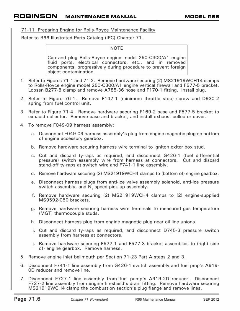
71-11 Preparing Engine for Rolls-Royce Maintenance Facility
Refer to R66 Illustrated Parts Catalog (IPC) Chapter 71.
NOTE
Cap and plug Rolls-Royce engine model 250-C300/A1 engine fluid ports, electrical connectors, etc., and in removed components, progressively during procedure to prevent foreign object contamination.
1. Refer to Figures 71-1 and 71-2. Remove hardware securing (2) MS21919WCH14 clamps to Rolls-Royce engine model 250-C300/A1 engine vertical firewall and F577-5 bracket. Loosen B277-8 clamp and remove A785-36 hose and F170-1 fitting. Install plug.
2. Refer to Figure 76-1. Remove F147-1 (minimum throttle stop) screw and D930-2 spring from fuel control unit.
3. Refer to Figure 71-4. Remove hardware securing F169-2 base and F577-5 bracket to exhaust collector. Remove base and bracket, and install exhaust collector cover.
4. To remove F049-09 harness assembly:
a. Disconnect F049-09 harness assembly’s plug from engine magnetic plug on bottom of engine accessory gearbox.
b. Remove hardware securing harness wire terminal to igniton exiter box stud.
c. Cut and discard ty-raps as required, and disconnect G426-1 (fuel differential pressure) switch assembly wire from harness at connectors. Cut and discard stand-off ty-raps at switch wire and F741-1 line assembly.
d. Remove hardware securing (2) MS21919WCH4 clamps to (bottom of) engine gearbox.
e. Disconnect harness plugs from anti-ice valve assembly solenoid, anti-ice pressure switch assembly, and N1 speed pick-up assembly.
f. Remove hardware securing (2) MS21919WCH4 clamps to (2) engine-supplied MS9592-050 brackets.
g. Remove hardware securing harness wire terminals to measured gas temperature (MGT) thermocouple studs.
h. Disconnect harness plug from engine magnetic plug near oil line unions.
i. Cut and discard ty-raps as required, and disconnect D745-3 pressure switch assembly from harness at connectors.
j. Remove hardware securing F577-1 and F577-3 bracket assemblies to (right side of) engine gearbox. Remove harness.
5. Remove engine inlet bellmouth per Section 71-23 Part A steps 2 and 3.
6. Disconnect F741-1 line assembly from G426-1 switch assembly and fuel pmp’s A919-0D reducer and remove line.
7. Disconnect F727-1 line assembly from fuel pump’s A919-2D reducer. Disconnect F727-2 line assembly from engine fireshield’s drain fitting. Remove hardware securing MS21919WCH4 clamp the combustion section’s plug flange and remove lines.

SEP 2012 R66 Maintenance Manual Chapter 71 Powerplant Page 71.7
71-11 Preparing Engine for Rolls-Royce Maintenance Facility (continued)
8. Remove A919-0D and A919-2D reducers, and G426-1 switch assembly, from fuel pump.
9. Remove hardware securing F593-3 plate to bottom of engine gearbox and remove plate.
10. Remove hardware securing engine-supplied rear PTO pad cover and remove cover.Remove bolt, washer, and G732-1 cap securing F018-1 clutch assembly in engine gearbox and remove clutch assembly.
11. Remove AN815-8D union from engine gearbox TANK VENT port, AN815-8D union or CV26-77 check valve (early R66s) from OIL OUTLET port, and AN815-10D union from OIL INLET port. Remove D745-3 pressure switch assembly from engine gearbox.
12. Cut and discard safety wire, remove hardware securing G200-1 mount and G200-2 cover from (top of) engine gearbox, and remove mount and cover. Remove residual B270-1 sealant.
71-12 Preparing Engine for Helicopter Installation
Refer to R66 Illustrated Parts Catalog (IPC) Chapter 71.
NOTE
Remove protective caps and plugs progressively during procedure to prevent foreign object contamination.
1. Refer to Figures 71-1 and 71-2. Position G200-2 cover and G200-1 mount on top of Rolls-Royce engine model 250-C300/A1 accessory gearbox as shown. Install hardware, standard torque bolts per Section 20-32, and torque stripe per Figure 5-1. Install 0.032-inch diameter lockwire and safety bolt heads together. Seal cover edges with B270-1 sealant.
2. Install D745-3 pressure switch assembly on front of engine gearbox as shown, special torque switch per Section 20-33, and torque stripe per Figure 5-1.
3. Install NAS617-10 packing on AN815-10D union and install union in engine gearbox OIL INLET port. Special torque union per Section 20-33 and torque stripe per Figure 5-1.
CAUTION
Installing CV26-77 check valve incorrectly can destroy oil tank.
4. Install NAS617-8 packing on AN815-8D union or CV26-77 check valve (early R66s; at straight thread) and install union or check valve (flow arrow to point away from engine) in engine gearbox OIL OUTLET port. Special torque union or check valve per Section 20-33 and torque stripe per Figure 5-1.
5. Install NAS617-8 packing on AN815-8D union and install union in engine gearbox TANK VENT port. Special torque union per Section 20-33 and torque stripe per Figure 5-1.
6. Inspect F018-1 clutch assembly splines and verify no evidence of galling. Also, verify end of thread insert is 0.090 - 0.110 inch inboard from tip of splined end of clutch housing; contact RHC Technical Support if thread insert position is incorrect. Lubricate clutch splines using B270-21 protectant. Insert clutch in engine gearbox, and install G732-1 cap, bolt, and washer at rear PTO pad. Standard torque bolt per Section 20-32 and torque stripe per Figure 5-1.

71-12 Preparing Engine for Helicopter Installation (continued)
7. Install engine-supplied rear PTO pad cover, and engine-supplied nuts and spacers. Special torque nuts per Section 20-33 and torque stripe per Figure 5-1.
8. Position F593-3 plate on bottom of engine gearbox and install aft bolt, finger tight.
9. Install G426-1 switch assembly in fuel pump BF (before filter) port. Special torque switch per Section 20-33 and torque stripe per Figure 5-1.
10. Install MS29512-3 packing on A919-0D reducer and install reducer in fuel pump AF (after filter) port. Special torque reducer per Section 20-33 and torque stripe per Figure 5-1.
11. Install MS29512-3 packing on A919-2D reducer and install reducer in fuel pump DRAIN port. Special torque reducer per Section 20-33 and torque stripe per Figure 5-1.
12. Connect F727-1 line assembly to fuel pump’s A919-2D reducer. Connect F727-2 line assembly to engine fireshield’s drain fitting. Install one MS21919WCH4 clamp around each line, install hardware securing lines to combustion section’s plug flange, and tighten screw. Special torque F727-1 line assembly nut at reducer per Section 20-33 and torque stripe per Figure 5-1; special torque F727-2 line assembly at fireshield’s drain fitting and torque stripe per Figure 5-1. Verify security.
13. Connect F741-1 line assembly to G426-1 switch assembly and fuel pump’s A919-0D reducer. Special torque nuts per Section 20-33 and torque stripe per Figure 5-1.
14. Install engine inlet bellmouth per Section 71-23 Part B steps 1 & 2. Install bellmouth cover.
15. To install F049-09 harness assembly:
a. Position F577-1 bracket assembly on F049-09 harness assembly’s D38999-20FC connector so connector’s main keyway will face outboard. Install and tighten hardware; verify security. Install bracket on (right side of) engine gearbox, special torque nuts per Section 20-33, and torque stripe per Figure 5-1.
b. Install MS21919WCH8 clamp around harness assembly and install clamp on F577-3 bracket assembly. Install and tighten hardware. Install bracket on (right side of) engine gearbox, special torque nuts per Section 20-33, and torque stripe per Figure 5-1.
c. Connect harness to D745-3 pressure switch assembly at connectors. Verify security. Install (2) MS3367-7-9 ty-raps to secure plug. Cinch ty-raps until snug without overtightening and trim tips flush with heads.
d. Connect harness plug to engine magnetic plug near oil line unions. Verify plug security.
e. Install harness wire terminals (white-to-white, green-to-green) on measured gas temperature (MGT) thermocouple studs. Install hardware, special torque nuts per Section 20-33, and torque stripe per Figure 5-1.
f. Verify (2) engine-supplied MS9592-050 brackets are installed on engine lube oil filter assembly per Rolls-Royce SB RR300-72-014. Install (2) MS21919WCH4 clamps around harness assembly and install clamps on brackets. Install and tighten hardware; verify security.
g. Connect harness plugs to anti-ice valve assembly solenoid, anti-ice pressure switch assembly, and N1 speed pick-up assembly. Verify security.
Page 71.8 Chapter 71 Powerplant R66 Maintenance Manual SEP 2012

71-12 Preparing Engine for Helicopter Installation (continued)
15. h. Install (2) MS21919WCH4 clamps around harness assembly and install clamps on (bottom of) engine gearbox. Install hardware, special torque nuts per § 20-33, and torque stripe per Figure 5-1.
i. Stand-off ty-rap G426-1 (fuel differential pressure) switch assembly’s wire from F741-1 line assembly using MS3367-4-9 ty-raps. Connect switch wire to harness at connectors. Install (2) MS3367-5-9 ty-raps to secure connectors to harness. Cinch ty-raps until snug without overtightening and trim tips flush with heads.
j. Install harness wire terminal on ignition exiter box stud. Install hardware, special torque nut per § 20-33, and torque stripe per Figure 5-1.
k. Connect harness plug to engine magnetic plug on bottom of engine gearbox. Verify plug security.
16. Refer to Figure 71-4. Verify F169-2 (exhaust) base and engine exhaust collector mating surfaces are clean and dry, and lay 0.25 inch bead 7020-3 ceramic putty on top of exhaust collector flange. Position F169-2 base and F577-5 bracket on exhaust collector and install hardware. Verify security. Remove excess putty. Install exhaust protective cover.
17. Refer to Figure 76-1. Install F147-1 (minimum throttle stop) screw in fuel control unit, special torque screw per § 20-33, and torque stripe per Figure 5-1. Install D930-2 spring.
18. Install (2) A215-016 o-ring and NAS617-12 packing on F170-1 fitting and install fitting in engine gearbox OB VENT port. Special torque fitting per § 20-33 and torque stripe per Figure 5-1. Position A785-36 hose and B277-8 clamp over fitting and tighten clamp. Verify security. Position (2) MS21919WCH14 clamps over hose and install and tighten hardware securing clamps to engine vertical fireshield and F577-5 bracket. Verify security.
APR 2017 Chapter 71 Powerplant Page 71.9

FIGURE 71-3 INDUCTION (STANDARD FILTER SHOWN)
Page 71.10 Chapter 71 Powerplant APR 2017

71-20 Induction
NOTE
Refer to § 12-70 for (Engine) Compressor Rinse and Wash procedures.
CAUTION
Never operate engine without G057-1 cage assembly installed. F771-1 (foam) filter assembly not required for flight; 146150-101 (inlet barrier filter) filter assemblies not required for flight.
CAUTION
Do not perform maintenance near engine inlet without cage and filter(s) or a temporary cover installed. Contact Rolls-Royce Customer Support if foreign objects enter inlet.
71-21 Air Filter Assembly
A. Description
The standard reticulated polyurethane foam filter is installed over the G057-1 cage assembly (refer to § 71-22) and secured with locking cords. The foam filter is a disposable filter not intended for cleaning, and is to be replaced on condition.
The optional G058-1 inlet barrier filter cage assembly is a separate installation with additional parts that secure the filters to the G057-1 cage assembly and that secure the assembly to the upper frame and firewall. A filter maintenance aid helps to determine if cleaning is required earlier than scheduled (every 300 hours or 1 year, whichever occurs first); certain operating environments require more frequent cleaning. The inlet barrier filter may be cleaned 15 times before replacement.
APR 2017 Chapter 71 Powerplant Page 71.11

Page 71.12 Chapter 71 Powerplant APR 2017
FIGURE 71-4 INDUCTION (INLET BARRIER FILTER SHOWN)

71-21 Air Filter Assembly (continued)
B. Removal
Standard Filter:
1. Remove tailcone cowling assembly per § 53-23.
2. Refer to Figure 71-3. Vacuum exterior of F771-1 filter assembly.
3. Disconnect F049-08 (bypass) switch assembly harness from airframe harness at connectors.
4. Loosen clamp securing tube to compresssor rinse nozzle and pull tube off of nozzle.
5. Release cord locks, loosen cords as required, and pull filter forward off of G057-1 cage assembly.
6. Install temporary cover over cage assembly.
Inlet Barrier Filter:
1. Remove tailcone cowling assembly per § 53-23.
2. Refer to Figure 71-4. Remove locking pin from strap assembly, release latch, and move strap assembly aside.
3. Remove 146150-101 filter from G058-1 cage assembly brackets; handle filter by the potting to avoid damaging pleated media.
4. Repeat steps 2 and 3 for other filter.
C. Installation
Standard Filter:
1. Refer to Figure 71-3. Remove temporary cover. Pull F771-1 filter assembly aft over G057-1 cage assembly and tighten cords as required. Verify security.
2. Install clamp and tube on compressor rinse nozzle and tighten clamp. Verify security.
3. Connect F049-08 (bypass) switch assembly harness to airframe harness at connectors.
4. Turn battery switch on. Verify annunciator panel warning segment illuminates when bypass doors are opened individually, then simultaneously. Turn battery switch off.
5. Install tailcone cowling assembly per § 53-23.
APR 2017 Chapter 71 Powerplant Page 71.13

71-21 Air Filter Assembly (continued)
C. Installation (continued)
Inlet Barrier Filter:
1. Service inlet barrier filter per Part D.
2. Refer to Figure 71-4. Remove temporary cover. Insert 146150-101 filter in G058-1 cage assembly brackets; handle filter by the potting to avoid damaging pleated media. Verify filter is properly seated.
3. Latch strap assembly. Adjust strap tension as required to ensure filter security, but without overtightening. Install locking pin.
4. Repeat steps 1 thru 3 for other filter.
5. Install tailcone cowling assembly per § 53-23.
D. Servicing
Standard Filter:
Filter should be removed & cleaned with water when visibly dirty. Replace filter if foam is visibly damaged or deteriorated.
Inlet Barrier Filter:
1. Visually inspect each filter assembly for obvious damage; replace filter(s) as required per Parts B and C.
2. To clean and dry each filter assembly:
a. Remove debris as practical from dirty side of filter assembly using a soft bristle brush.
CAUTION
Use only ZOK 27 cleaner to clean filter media.
CAUTION
Do not use steam, a high-pressure washer, or compressed air to clean filter assemblies.
b. Using a spray bottle, apply ZOK 27 cleaner to both sides of filter media until saturated. Allow to soak for minimum 10 minutes (30 minutes or more may be necessary for high-contaminant environments).
c. Rinse filter with clean water in opposite direction of airflow (from clean side) using low-pressure stream. Orient filter so pleats are vertical; rinse side-to-side starting at the top and working downward. Proceed downward only when water runoff is clear.
Page 71.14 Chapter 71 Powerplant APR 2017

APR 2017 Chapter 71 Powerplant Page 71.15
71-21 Air Filter Assembly (continued)
D. Servicing (continued)
Inlet Barrier Filter (continued):
2. d. Rinse filter in direction of airflow per step 2c.
e. Rotate filter top to bottom and perform steps 2c and 2d.
CAUTION
Do not use compressed air, or heat from any source, to dry filter assemblies.
f. Shake off excess water. Allow filter assembly to dry at ambient temperature (above freezing), protected from contaminants.
3. Using a permanent marker, mark cleaned filter(s) with “X” through last unmarked indented potting number (1–15). Replace 146150-101 filter at the next service interval after 15 cleanings.
4. For each filter: Visually inspect filter pleats for straightness. Visually inspect filter media for small ruptures, tears, or holes. Visually inspect potting compound for cracks, gouges, or gaps between filter and compound. Replace filter(s) as required per Parts B and C.
CAUTION
Verify filter media is completely dry before applying oil. Use only approved oil; never put an un-oiled filter in service.
5. Apply 4.5 oz total 100100-045 filter oil to each filter. Using squeeze bottle with tip, apply a small stream of oil (sparingly) along entire peak of each pleat on both sides of filter (save some for final application). Let filter sit for 30 minutes minimum as oil “wicks” into surrounding filter media. Apply remaining oil not to exceed quantity above to any areas that are still white or not yet uniform in color.
6. Push yellow button to reset filter maintenance aid.

Page 71.16 Chapter 71 Powerplant APR 2017
71-21 Air Filter Assembly (continued)
E. Scheduled Inspections
Standard Filter:
Refer to § 5-45 100-Hour/Annual Inspection. Replacement of F771-1 filter assembly is on condition.
Inlet Barrier Filter:
Refer to § 5-45 100-Hour/Annual Inspection.
Service 146150-101 filters per Part D every 300 hours or 1 year, whichever occurs first. Replace 146150-101 filters at the next service interval after 15 cleanings.
F. Special Inspections
Standard Filter:
If pilot reports AIR FILTER caution segment illuminates during engine operation, when engine is shut down, verify proper function of bypass switch. Turn battery switch on. Verify caution segment illuminates when bypass doors are opened individually, then simultaneously. Turn battery switch off. If bypass switch functions properly, replace F771-1 filter assembly per Parts B and C.
If pilot reports a failed power assurance check (refer to § 5-43), replace F771-1 filter assembly per Parts B and C.
Inlet Barrier Filter:
If pilot reports AIR FILTER caution segment illuminates during engine operation, when engine is shut down, verify proper function of bypass switch. Turn battery switch on. Verify caution segment illuminates when bypass doors are opened individually, then simultaneously. Turn battery switch off. If bypass switch functions properly, service 146150-101 filters per Part D.
If pilot reports a failed power assurance check (refer to § 5-43), service 146150-101 filters per Part D.
If filter maintenance aid indicates in red zone, service 146150-101 filters per Part D.
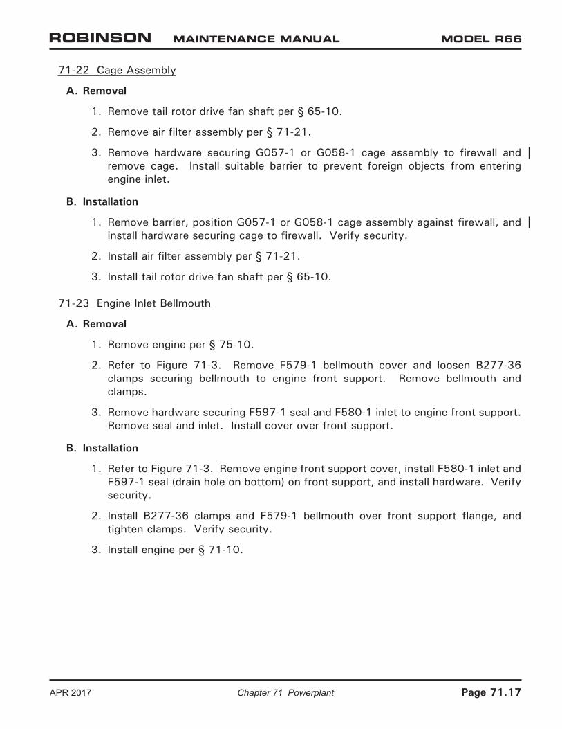
71-22 Cage Assembly
A. Removal
1. Remove tail rotor drive fan shaft per § 65-10.
2. Remove air filter assembly per § 71-21.
3. Remove hardware securing G057-1 or G058-1 cage assembly to firewall and remove cage. Install suitable barrier to prevent foreign objects from entering engine inlet.
B. Installation
1. Remove barrier, position G057-1 or G058-1 cage assembly against firewall, and install hardware securing cage to firewall. Verify security.
2. Install air filter assembly per § 71-21.
3. Install tail rotor drive fan shaft per § 65-10.
71-23 Engine Inlet Bellmouth
A. Removal
1. Remove engine per § 75-10.
2. Refer to Figure 71-3. Remove F579-1 bellmouth cover and loosen B277-36 clamps securing bellmouth to engine front support. Remove bellmouth and clamps.
3. Remove hardware securing F597-1 seal and F580-1 inlet to engine front support. Remove seal and inlet. Install cover over front support.
B. Installation
1. Refer to Figure 71-3. Remove engine front support cover, install F580-1 inlet and F597-1 seal (drain hole on bottom) on front support, and install hardware. Verify security.
2. Install B277-36 clamps and F579-1 bellmouth over front support flange, and tighten clamps. Verify security.
3. Install engine per § 71-10.
APR 2017 Chapter 71 Powerplant Page 71.17

FIGURE 71-5 EXHAUST
Page 71.18 Chapter 71 Powerplant APR 2017

71-30 Exhaust Weldment
A. Removal
1. Remove engine cowling assembly per § 53-21.
2. Refer to Figure 71-5. Remove hardware securing F173-1 struts to F169-1 exhaust weldment and engine, and remove struts.
3. Loosen clamp(s) securing (accessory gearbox vent) tubes/hose to exhaust; pull tubes/hose off of exhaust weldment.
4. Remove three fasteners securing exhaust weldment to engine exhaust collector. Carefully lift exhaust weldment up and off of F169-2 base flange, and remove exhaust weldment.
5. As required, remove hardware securing base and F577-5 bracket (early R66s) to exhaust collector and remove base. Install exhaust collector cover.
NOTE
F169-1 exhaust weldment material is Type 321 CRES sheet.
B. Installation
1. Refer to Figure 71-5. If F169-2 base is installed, proceed to step 3. Verify base and engine exhaust collector mating surfaces are clean and dry, and lay 0.25 inch bead 7020-3 ceramic putty on top of exhaust collector flange.
2. Position F169-2 base and F577-5 bracket (early R66s) on exhaust collector and install hardware. Verify security. Remove excess putty.
3. Position F169-1 exhaust weldment on base and install three fasteners securing exhaust weldment to exhaust collector.
4. Install hardware securing F173-1 struts to exhaust weldment and engine. Special torque engine tee-bolts per § 20-33.
5. Position (accessory gearbox vent) tubes/hose with clamp(s) over exhaust weldment vent tube. Orient clamp screw(s) (and any slight bunching of hose, early R66s) is on top within 30°, and tighten clamp(s). Verify security.
6. Install engine cowling assembly per § 53-21.
APR 2017 Chapter 71 Powerplant Page 71.19

71-40 Accessories
71-41 Starter-Generator
A. Removal
1. Remove engine cowling assembly per § 53-21.
2. Refer to Figure 71-1. Verify heat shrink stamping is legible (or mark wires and cables) and remove hardware securing wires and cables to starter-generator studs.
3. Remove starter-generator per RR300 Series Operation and Maintenance Manual (OMM).
B. Installation
1. Install starter-generator per RR300 Series Operation and Maintenance Manual (OMM).
2. Refer to Figure 71-1. Install wires and cables on starter-generator studs according to stamping. Install hardware, special torque nuts per § 20-33, and torque stripe per Figure 5-1.
3. Install engine cowling assembly per § 53-21.
71-42 Generator Control Unit (GCU)
A. Removal
1. Open baggage compartment door. Remove hardware securing G248-1 cover (battery compartment) to inner compartment and remove cover.
2. Disconnect F049 (GCU) electrical harness plug from GCU. Remove mounting hardware, and remove GCU. Cap receptacles.
B. Installation
1. Open baggage compartment door. Position GCU on inner compartment shelf and install mounting hardware. Verify security.
2. Remove caps and connect F049 (GCU) electrical harness plug to GCU.
NOTE
Verify MS3106R24-28S plug is fully-engaged in GCU receptacle. Rotate plug collar until tight.
3. Install hardware securing G248-1 cover to inner compartment. Close and secure baggage door.
Page 71.20 Chapter 71 Powerplant APR 2017

71-43 Engine Monitoring Unit (EMU)
NOTE
The electronic monitoring unit (EMU) is a serialized component assigned to the engine. When removing the engine, remove the engine's EMU per § 71-43, as required.
A. Removal
1. Remove hardware securing F003-4 (RH) seat back assembly to cabin.
2. Disconnect F059-01 (cabin) electrical harness "EMU" plug and F049-07 (USB) harness plug from EMU.
3. Remove hardware securing EMU to bulkhead and remove EMU. Cap receptacles.
B. Installation
1. Remove caps, position EMU on bulkhead, and install hardware. Verify security.
2. Connect F059-01 (cabin) electrical harness "EMU" plug and F049-07 (USB) harness plug to EMU.
3. Turn battery switch on. After 10 seconds press annunciator panel test button; verify EMU amber warning segment illuminates, and is solid, indicating normal EMU operation. (See R66 Pilot's Operating Handbook Section 7 for complete description.) Turn battery switch off.
4. Install hardware securing F003-4 (RH) seat back assembly to cabin.
C. Downloading EMU Data
NOTE
An EMU USB receptacle is located inside the aft right seat baggage compartment, on the underside of the aft ledge. Use a flashlight and mirror when inserting USB cable into receptacle.
Download summary or diagnostic data per RR300 Series Operation and Maintenance Manual (OMM).
D. Troubleshooting
1. Turn battery switch off and disconnect battery ground cable from battery negative terminal.
2. Open circuit breaker panel and verify integrity of fuse for EMU; replace fuse as required. Close circuit breaker panel.
3. Access annunciator panel plug and verify connector is fully seated on G198 annunciator panel receptacle.
APR 2017 Chapter 71 Powerplant Page 71.21
Page 71.22 Chapter 71 Powerplant APR 2017
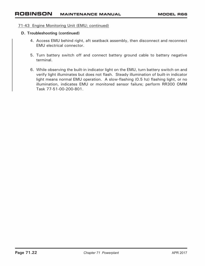
71-43 Engine Monitoring Unit (EMU; continued)
D. Troubleshooting (continued)
4. Access EMU behind right, aft seatback assembly, then disconnect and reconnect EMU electrical connector.
5. Turn battery switch off and connect battery ground cable to battery negative terminal.
6. While observing the built-in indicator light on the EMU, turn battery switch on and verify light illuminates but does not flash. Steady illumination of built-in indicator light means normal EMU operation. A slow-flashing (0.5 hz) flashing light, or no illumination, indicates EMU or monitored sensor failure; perform RR300 OMM Task 77-51-00-200-801.