Chapter 7 Slot Antennas - W1GHZ.orgChapter 7 Slot Antennas Paul Wade W1GHZ ©2000,2001,2019 7.0...
14
Chapter 7 Slot Antennas Paul Wade W1GHZ ©2000,2001,2019 7.0 Introduction Slot antennas are popular omnidirectional microwave antennas. These antennas feature omnidirectional gain around the azimuth with horizontal polarization. Waveguide slot antennas, usually with an array of slots for higher gain like Figure 7-1, are used at frequencies from 2 to 24 GHz, while simple slotted-cylinder antennas like Figure 7-2 are more common at the UHF and lower microwave frequencies where the size of a waveguide becomes unwieldy. The Alford slot is an enhanced form of the slotted- cylinder antenna with somewhat higher gain. 7.1 Slots and Dipoles A thin slot in an infinite ground plane is the complement to a dipole in free space. This was described by H.G. Booker 1 , who extended Babinet’s Principle 2,3 from optics to show that the slot will have the same radiation pattern as a dipole with the same
Transcript of Chapter 7 Slot Antennas - W1GHZ.orgChapter 7 Slot Antennas Paul Wade W1GHZ ©2000,2001,2019 7.0...

Chapter 7
Slot Antennas
Paul Wade W1GHZ ©2000,2001,2019
7.0 Introduction
Slot antennas are popular omnidirectional microwave
antennas. These
antennas feature
omnidirectional gain
around the azimuth
with horizontal
polarization.
Waveguide slot
antennas, usually with
an array of slots for
higher gain like Figure
7-1, are used at
frequencies from 2 to
24 GHz, while simple
slotted-cylinder
antennas like Figure 7-2
are more common at
the UHF and lower
microwave frequencies
where the size of a
waveguide becomes
unwieldy. The Alford
slot is an enhanced
form of the slotted-
cylinder antenna with
somewhat higher gain.
7.1 Slots and Dipoles
A thin slot in an infinite ground plane is the complement
to a dipole in free space. This was described by H.G.
Booker1, who extended Babinet’s Principle
2,3 from optics
to show that the slot will have the same radiation pattern as a dipole with the same

dimensions as the slot, except that the E- and H-fields are swapped, as illustrated in
Figure 7-3 — the slot is a magnetic dipole rather than an electric dipole. As a result, the
polarization is rotated 90º, so that radiation from a vertical slot is polarized horizontally.
For instance, a vertical slot has the same pattern as a horizontal dipole of the same
dimensions — and we are able to calculate the radiation pattern of a dipole. Thus, a
longitudinal slot in the broad wall of a waveguide radiates just like a dipole perpendicular
to the slot.
Figure 3 – Equivalence of slot and dipole; fields are swapped
Watson4 describes a proof of Babinet’s Principle, attributed to Sommerfeld, working in a
Riemann space. This mind-expanding concept is by no means necessary for
understanding slot antennas, but I’ve never seen Riemann geometry actually used.
7.2 Waveguide Slot Antennas
Waveguide slot antennas are often used as omnidirectional microwave antennas.
According to Watson4, the slot array was invented in 1943 at McGill University in
Montreal. Unique features of these antennas are horizontal polarization and
omnidirectional gain around the azimuth. They are also simple, rugged, and fairly easy to
build. While they have been described in several articles in the ham literature, all the
articles seem to have the same dimensions, suggesting a common genesis.

The most available reference for waveguide slot antennas is Jasik’s5 Antenna
Engineering Handbook; the dimensions there look remarkably similar to the ham articles.
The third edition6, by R. C. Johnson, has some additional information. We will try to
explain how a waveguide slot antenna works, how to design one, to give some hints for
successful fabrication, and to make some suggestions for further experimentation.
The waveguide slot antennas we will be discussing have longitudinal slots in the broad
face of standard rectangular waveguide, parallel to the length of the guide. Figure 7-1 is
a photograph of a typical waveguide slot antenna, with a total of 12 slots, six on each
side, in WR-90 X-band waveguide for 10 GHz operation. There are several other forms
of waveguide slot antennas with slots in various locations and in other waveguide shapes;
I refer you to Jasik5 or Johnson
6 for details.
7.2.1 Arrays of slots in waveguide
We are able to calculate the radiation pattern for an array of dipoles as well as a single
dipole. The usual technique is to multiply the dipole pattern by the pattern of an array of
ideal radiators. An array of slots may be configured to shape the radiation pattern as
desired. Two-dimensional arrays of slots may be used to form a beam antenna, but there
are easier ways to fabricate a beam antenna, so we will first concentrate on
omnidirectional antennas, with a linear array of slots.
The vertical collinear array, consisting of several vertical dipoles connected end-to-end,
is a popular VHF omnidirectional antenna with vertical polarization. A vertical dipole
has an omnidirectional pattern in the horizontal plane, or azimuth, and adding additional
dipoles concentrates the beam into a flatter vertical beam to provide gain. Try to
visualize the pattern of a single dipole as a donut or bagel with the vertical dipole passing
through the hole; adding more collinear dipoles squishes the donut flat, like a pancake
with a hole.
A waveguide slot antenna has a vertical row of slots along the length of a vertical
waveguide, with the array of slots increasing the gain by flattening the vertical beam.
Since the slots are oriented vertically along the guide, the polarization is horizontal — a
comparable dipole antenna would be a stack of horizontal dipoles. Increasing the number
of slots provides more gain but flattens the beam (donut) into a narrower elevation angle
(pancake). Since a slot in one side of the physical waveguide does not radiate uniformly
on both sides like a theoretical slot in infinite plane, an identical row of slots is added on
the far side of the waveguide to make the radiation pattern more uniform.
Design of an antenna array involves a number of details: cutting the elements to
resonance, spacing the elements properly, splitting the power to distribute to the
elements, feeding the elements in phase through a harness of transmission lines, and
providing a mounting structure for each element. For traditional arrays, each of these
items may be attacked separately, but the waveguide slot antenna combines them all into

a single piece of waveguide — we must find a set of dimensions that satisfies all the
requirements simultaneously.
7.2.2 Slot impedance in waveguide
A longitudinal slot cut into the wall of a waveguide interrupts the transverse current
flowing in the wall, forcing the current to travel around the slot, which induces an electric
field in the slot. The position of the slot in the waveguide determines the current flow.
Thus, the position determines the impedance presented to the transmission line and the
amount of energy coupled to the slot and radiated from the slot. Figure 7-4 shows a
cross-sectional view of a slot in a rectangular waveguide, showing the electric fields
calculated using Zeland Fidelity7 software. Below the cross-sectional plot is a graph
illustrating how the electric field intensity varies sinusoidally across the waveguide cross-
section. The current in the walls of the guide must be proportional to the difference in
electric field between any two points. Therefore, a slot in the exact center of the broad
wall of the waveguide will not radiate at all, since the electric field is symmetrical around
the center of the guide and thus is identical at both edges of the slot. As the slot is
positioned away from the centerline, the difference in field intensity between the edges of
the slot is larger, so that more current is interrupted and more energy is coupled to the
slot, increasing radiated power.
As we approach the sides of the
waveguide, the field is very small, since
the sidewalls are short circuits for the
electric field. The induced current must
also be small; longitudinal slots far from
the center or in the sidewall will not
radiate significantly. However, angled
slots in the sidewalls can be effective
radiators; see Jasik5 or Johnson
6 for details.
From the point of view of the waveguide,
the slot is a shunt impedance across the
transmission line, or an equivalent
admittance loading the transmission line
(admittance is the reciprocal of
impedance). Slots further from the
centerline of the guide present a larger
admittance (lower impedance) to the
transmission line. When the admittance of
the slot (or combined admittance of all the
slots) equals the admittance of the guide,
then we have a matched transmission line,
or low VSWR.

If we wished to make a slot antenna in a circular waveguide, we would need to locate the
point of maximum electric field. In a rectangular waveguide, the maximum electric field
is conveniently located at the centerline of the broad wall, while in circular guide the
maximum electric field is on a line through the center but may be oriented in any
direction. So we would require a mechanism to fix the alignment of the electric field in
the circular waveguide, and to keep it from rotating when encountering a discontinuity
such as a slot. This difficulty makes rectangular waveguide much more attractive for slot
antennas.
7.2.3 Waveguide slot array design
A sketch of a waveguide slot antenna with the pertinent dimensions is shown in Figure
7-5. The first design consideration is that the slots be resonant so that they provide a
resistive load to the (waveguide) transmission line.
Figure 7-5 – Waveguide Slot Antenna Dimensions

Normally, it is desirable for an omnidirectional antenna to radiate in a horizontal
(azimuth) plane. This is achieved by feeding all the slots in phase. The radiation pattern
may be tilted upward or downward (visualize a shallow cone) by changing the phasing of
the slots, if desired. I’m told that vertical collinear arrays for ground-based aviation
antennas are sometimes designed with a pattern tilted upward.
The slots are fed in phase by spacing their centers at electrical half-wavelength intervals
along the waveguide. The electrical wavelength in waveguide is longer than in free
space, so we must calculate the guide wavelength:
where λλλλC , the cutoff wavelength, is equals to twice the wide dimension of the
waveguide.
If the spacing is wrong, or if the frequency is changed significantly so the spacing is no
longer λλλλg/2, then the slots will not be fed in phase and the beam will be tilted — we can
make a beacon for aliens or earthworms.
A half-wavelength of transmission line has the useful property of repeating impedance:
the input and output impedances are the same. As a result, the impedances, or
admittances, of all the slots appear in parallel. Figure 7-6 shows this schematically.
Each parallel resistor represents one slot, so there must be N resistances in parallel.
Figure 7-6 Schematic Diagram of Waveguide Slot Array
The center of the last slot is a guide quarter-wavelength from the closed end of the
waveguide. We know that a short-circuited quarter-wavelength stub of transmission line
appears as an open-circuit, so that the closed end does not affect the impedance.
Sometimes the closed end is spaced ¾ λλλλg for mechanical reasons; the additional half-
wavelength is transparent.
22
0
11
1
−
=
C
g
λλλλλλλλ
λλλλ

Assuming that we are successful in making the slots resonant and spacing them exactly
λλλλg/2, then the admittance Y is purely resistive and the calculation is extremely simple:
adding N identical admittances together, where N is the number of slots. The books
show the admittance normalized to the impedance of the waveguide, so that the slot
admittances should add up to 1.0; thus, each slot should have an admittance of 1/N.
Spacing the slot centers at ½λλλλg intervals in the waveguide is an electrical spacing of 180°
— each slot is exactly out of phase with its neighbors, so their radiation will cancel each
other. However, slots on opposite sides of the centerline of the guide will be out of phase
(180°), so we can alternate the slot displacement around the centerline and have a total
phase difference of 360° between slots, putting them back in phase.
A photograph of a complete waveguide slot antenna is shown in Figure 7-1. This
example has 6 slots on each side for at total of 12 slots. The slots have identical length
and spacing along the waveguide. Note how the slot position alternates about the
centerline of the guide. The far wall of the waveguide has an identical slot pattern, so
that you can see through the slots. If the pattern on the far wall were reversed, the two
sides would have opposite phasing and the resultant radiation pattern would have a null
on each side.
A simple way to estimate the gain of a slot antenna is to remember that it is an array of
dipoles. Each time we double the number of dipoles, we double the gain, or add 3 dB.
Thus, a 16 slot array would have a gain of about 12 dBd. The approximate gain formula
is thus Gain = 10log(N) dB, for N total slots.
Since it is really the vertical aperture of the slots rather than just the number of slots that
determine the gain and vertical beamwidth, DK3BA and DG8SG8 give better formulas:
and
degrees
2N
50.7 Beamwidth 0
gslotspacin⋅⋅=
λλλλ
where N is the total number of slots and slotspacing is normally half the guide
wavelength.
Since the waveguide slot antenna is a resonant antenna, requiring resonant slots and half-
wavelength spacing, it is not particularly broadband. Good performance might be
expected over a bandwidth of less than 10% for a small number of slots, and even smaller
bandwidth for a larger array. Thus, it is important to get the dimensions right for the
operating frequency.
dB N
log 10 Gain 0
⋅=
λλλλ
gslotspacin

7.2.4 Slot dimensions
Several amateur slot antenna designs have been published: a 12-slot version for 10 GHz
by WB6IGP9, a 12-slot antenna with “wings” for 10 GHz by K5SKX and WA5VJB
10, as
well as a Mathcad routine for slot design by KB7TRZ11
which was converted to a BASIC
program by W6OYJ12
. The KB7TRZ routine uses dimensions based on the work of A. F.
Stevenson13
from 1948. The following formula for normalized slot conductance, used to
calculate the slot displacement, is from Stevenson:
a
xsin
2cos
b
a 2.09
G
G 202
0waveguide
slotππππ
λλλλ
πλπλπλπλ
λλλλ
λλλλ
⋅⋅=
g
g
where a and b are the large and small dimensions of the waveguide, respectively, and x is
the slot displacement from centerline.
Conductance G is the real (resistive) part of admittance Y; if the slot is resonant, then the
admittance is has no reactive component and only the conductance is left. The formula
assumes a resonant slot in an infinitely thin wall of perfectly conducting material. The
resonant slot length is assumed to be a half-wavelength in free space. If we use the
normallized conductance, Gslot / Gwaveguide, then we don’t have to clutter the calculations
with the waveguide conductance.
Antennas made using dimensions from this formula work well, but usually require some
adjustment to achieve low VSWR. WA1VVH reports successful adjustment by inserting
shorting plugs to vary the length of the closed end.
Practical dimensions were measured in WR-90 waveguide by R. J. Stegen14
at 9.375
GHz. The curves from this paper are reproduced in the Antenna Engineering
Handbook6,7
. Most recent work seems to be aimed at reconciling computer calculations
with the actual data; much of the work is by R. S. Elliott. His book15
, Antenna Theory
and Design, has a good treatment of waveguide slot antenna design, and he has also
contributed the chapter on waveguide slot antennas in the Antenna Handbook by Lee and
Lo16
.
The first conclusion from Stegen’s measured data is that the slot length is not exactly a
half-wavelength. This is hardly surprising — we have all made wire dipoles that are
shorter than ½ wavelength using the formula in the Radio Amateurs Handbook17
— so
why would we expect an equivalent slot to be exactly a half-wavelength long? Elliott
and Kurtz18
estimate that a square-ended slot in an infinitely thin wall would have a
resonant length of 0.464λ0. In WR-90 waveguide with real wall thickness and rounded
ends, the resonant length increases to 0.483λ0. This length must then be corrected as the
slot is moved off-center in the waveguide, using Stegen’s measured data.
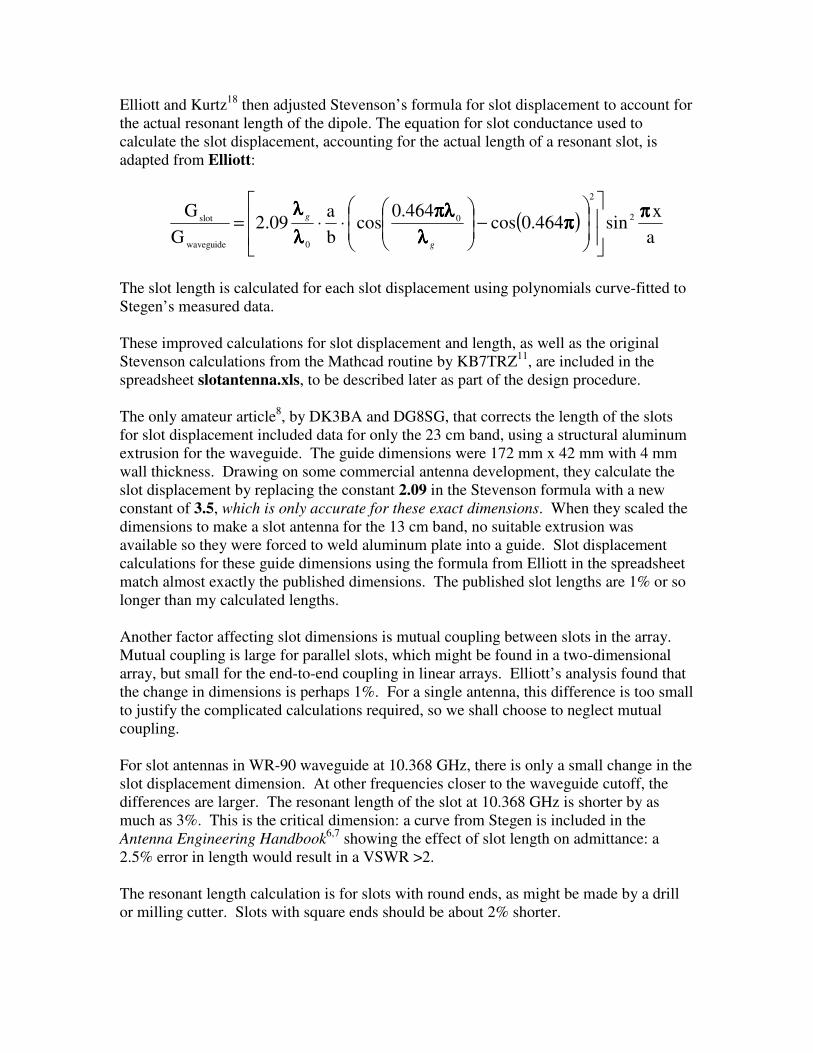
Elliott and Kurtz18
then adjusted Stevenson’s formula for slot displacement to account for
the actual resonant length of the dipole. The equation for slot conductance used to
calculate the slot displacement, accounting for the actual length of a resonant slot, is
adapted from Elliott:
( )a
xsin464.0cos
464.0cos
b
a 2.09
G
G 2
2
0
0waveguide
slotππππ
ππππλλλλ
πλπλπλπλ
λλλλ
λλλλ
−
⋅⋅=
g
g
The slot length is calculated for each slot displacement using polynomials curve-fitted to
Stegen’s measured data.
These improved calculations for slot displacement and length, as well as the original
Stevenson calculations from the Mathcad routine by KB7TRZ11
, are included in the
spreadsheet slotantenna.xls, to be described later as part of the design procedure.
The only amateur article8, by DK3BA and DG8SG, that corrects the length of the slots
for slot displacement included data for only the 23 cm band, using a structural aluminum
extrusion for the waveguide. The guide dimensions were 172 mm x 42 mm with 4 mm
wall thickness. Drawing on some commercial antenna development, they calculate the
slot displacement by replacing the constant 2.09 in the Stevenson formula with a new
constant of 3.5, which is only accurate for these exact dimensions. When they scaled the
dimensions to make a slot antenna for the 13 cm band, no suitable extrusion was
available so they were forced to weld aluminum plate into a guide. Slot displacement
calculations for these guide dimensions using the formula from Elliott in the spreadsheet
match almost exactly the published dimensions. The published slot lengths are 1% or so
longer than my calculated lengths.
Another factor affecting slot dimensions is mutual coupling between slots in the array.
Mutual coupling is large for parallel slots, which might be found in a two-dimensional
array, but small for the end-to-end coupling in linear arrays. Elliott’s analysis found that
the change in dimensions is perhaps 1%. For a single antenna, this difference is too small
to justify the complicated calculations required, so we shall choose to neglect mutual
coupling.
For slot antennas in WR-90 waveguide at 10.368 GHz, there is only a small change in the
slot displacement dimension. At other frequencies closer to the waveguide cutoff, the
differences are larger. The resonant length of the slot at 10.368 GHz is shorter by as
much as 3%. This is the critical dimension: a curve from Stegen is included in the
Antenna Engineering Handbook6,7
showing the effect of slot length on admittance: a
2.5% error in length would result in a VSWR >2.
The resonant length calculation is for slots with round ends, as might be made by a drill
or milling cutter. Slots with square ends should be about 2% shorter.

The final dimension is the slot width. While the KB7TRZ calculations specified one-
twentieth of a wavelength, Stegen’s measurements were based on a slot width of 0.062
inch (1/16 inch, or 1.5875 mm) in WR-90 waveguide — a convenient size. For other
waveguide sizes, the slot width should probably be scaled accordingly, but small
variations to fit available tooling should not be critical.
For each microwave band, several of the standard waveguide sizes are usable. At 10
GHz, for instance, WR-75 and WR-112 are usable as well as the ubiquitous WR-90.
When we enter the inner dimensions of each size into the spreadsheet, we find that,
compared to WR-90, the WR-75 slot dimensions have a smaller displacement from the
centerline and a larger slot spacing, since λg is larger in the smaller waveguide.
Increasing spacing in an antenna array tends to produce larger sidelobes; in this case, the
sidelobes are in the elevation pattern. The change in slot dimensions for WR-112 is just
the opposite: a larger displacement and a smaller slot spacing. The larger displacement
makes the tolerance less critical. Since both effects, sidelobe levels and dimensional
tolerance, tend to favor the larger waveguide, it would seem preferable to choose the
largest available waveguide that is usable at a given frequency. Later, we will see that
the largest size might not be the best choice, but the small size will always require tighter
construction tolerances.
Updates
Since this was written in 2001, two improvements have been found. In 2005, Petr Kauler
([email protected]) suggested that I had made an error in the spreadsheet calculations, in
the slot offset in cell G36. The formula used is
=(WG_a/PI())*SQRT(ASIN(New_Y))
While the correct form based on the equation should be:
=(WG_a/PI())*ASIN(SQRT(New_Y))
The difference in results seemed pretty small, and furthermore, previous versions of slot
antenna spreadsheets by others had used the same form, so I figured it was close enough.
Remember that some of the other numbers in the spreadsheet were found by eyeballing
graphs in old papers, so they aren’t accurate to six decimal places.
In 2009, Dan Welch, W6DFW [SK], reported that he had built some 24-slot versions for
10 GHz using a precision CNC machine. These accurately machined antennas,
calculated for 10.368 GHz, were centered at about 10.220 GHz.
I changed the formula in the spreadsheet slotantenna.xls, and Dan made a 24-slot
antenna with the new, slightly different, dimensions. Dan measured this one as centered
at 10.331 GHz, with about 20 dB return loss and about 200 MHz bandwidth, so it is good
with no tuning. He sent another antenna to me, shown in Figure 7-8. It is a thing of
beauty, and I have confirmed the results.

Figure 7-8 – Waveguide 24-slot antenna for 10.368 GHz by W6DFW
The small difference in dimensions should not affect the antenna performance, only the
return loss, so you don’t have to throw away your old slot antenna. For those who made them
with a drill and a file, there shouldn’t be any difference – and I respect your ham spirit for
getting the job done with what you have.
7.2.5 Waveguide slot antenna design procedure
We can summarize the design procedure for a waveguide slot antenna:
1. Choose the number of slots required for the desired omnidirectional gain and vertical
beamwidth.
2. Choose a waveguide size appropriate for the operating frequency. Smaller sizes
require more critical construction tolerances.
3. Calculate the wavelength in the waveguide at the operating frequency.
4. Determine the slot position from centerline for a normalized admittance of 1/N,
where N is the number of slots in both walls of the waveguide.
5. Determine the slot length for resonance at the operating frequency.
6. The slot width should be roughly one-twentieth of a wavelength, or proportional to
0.062 inches in WR-90 waveguide. Since cutting tools only come in certain sizes,
choose the closest smaller size for the slot width. With CNC machining, this is not a
problem.
A convenient way to make the design calculations is to use the Microsoft Excel
spreadsheet slotantenna.xls available at http://www.w1ghz.org/slotantenna.xls. A
typical calculation using the spreadsheet is shown in Figure 7-7.

Waveguide Slot Antenna Calculatorupdated 5/30/2002 W1GHZ 2000,2009*update 3/2009 - Offset calculation correction
Parameter Metric Inches Metric Inches
ENTER INPUT PARAMETERS HERE:Frequency 10.368 GHz 10.368 GHz
Waveguide large dim 22.86 mm 0.9 inch
Waveguide small dim 10.16 mm 0.4 inch
Number of slots 16 16 total on two sides
Estimated Performance Gain = 10.1 dB Beamwidth= 9.8 deg
READ FINAL SLOT DIMENSIONS HERE:
old from KB7TRZ improved from ElliottOffset from centerline 2.13 mm 0.084 inch 2.35 mm 0.092 inch
Length 14.47 mm 0.570 inch 14.04 mm 0.553 inch
Width 1.87 mm 0.074 inch 1.59 mm 0.063 inch
Slot spacing center to center18.69 mm 0.736 inch 18.69 mm 0.736 inch
End space = 1/4 wave 9.34 mm 0.368 inch 9.34 mm 0.368 inch
End space = 3/4 wave 28.03 mm 1.103 inch 28.03 mm 1.103 inch
End space is from shorted end to center of last slot
Wavelength - free space 28.94 mm 1.139 inchWavelength - cutoff 45.72 mm 1.800 inchGuide wavelength 37.37 mm 1.471 inch
INTERMEDIATE TERMS -- DON"T MESS WITH THESE!
Gslot 0.0625 0.0625 enter taper admittance here
G1 0.7322 0.6028Y 0.0854 0.1037
Offset calculation: Mathcad from KB7TRZ: New offset calc from Elliott:OFFSET 2.13 mm 0.084 inches 2.35 mm 0.092 inch
CORRECTED OFFSET **
2.16 mm 0.085 inches 2.39 mm 0.094 inch
Offset calculation: BASIC from W6OYJ:AG 0.09 mmOffset 2.13 mm 0.084 inches
Slot Length Calculation from Stegen curves:Slot in wavelengths 0.4851Slot Length 14.04 mm 0.553 inch
* Correction tested on CNC machining and measurement by Dan Welch W6DFW** correction from Petr Kauler [email protected]

7.2.6 Waveguide slot antenna performance
I began with the two 10 GHz slot antennas: the twelve-slot version shown in Figure 7-1
and a larger one with 24 slots total. Bob Barrett, WA1ZJG [SK], machined these from
the original Stevenson directions.
Then Dave McGee, W2KV,
measured the radiation patterns
shown in Figure 7-9 on a
commercial antenna range.
Obviously, I didn’t do much of the
heavy lifting!
The measured radiation patterns in
Figure 7-8 show the expected
difference between the two
versions: the larger antenna with
twice as many slots has about 3 dB
more gain, with a narrower beam in
the elevation pattern. Both
elevation patterns have large
sidelobe levels; the 24-slot version
has roughly twice as many
sidelobes as the 12-slot version.
Neither azimuth pattern is truly
omnidirectional — the gain varies
as much as 10 dB over the full 360°
azimuth.
The larger slot antenna, with 24
slots, has a gain as high as 16 dB in
some directions. While this is very
good gain for an omnidirectional
antenna, it is a much lower gain
antenna than a small dish or even a
reasonably large horn. Using a slot
antenna for microwave
communications may lead to
frustration — believe me, I’ve tried
and not been heard.
I used the Zeland Fidelity7 software to calculate the radiation patterns for a computer
model of a 12 slot antenna, with the Stevenson dimensions. These patterns, shown in
Figure 7-9, are very similar to the measured patterns shown in Figure 7-8. Both
measured and calculated patterns show large variations in gain around the azimuth, as
well as significant sidelobes at high elevation angles, wasting energy into space.

Since all the antennas so far, both measured and calculated, used the original Stevenson
dimensions, we may conclude that these dimensions will yield a working omnidirectional
antenna but not a really good one.
Figure 7-10 – Radiation Patterns of 12-slot WR-90 antenna at 10.368 GHz with uniform amplitude distribution, simulated by Zeland Fidelity