Chapter 7 Registers and Register Transfers
33
Charles Kime © 2008 Pearson Education, Inc. (Hyperlinks are active in View Show mode) Chapter 7 – Registers and Register Transfers Part 3 – Control of Register Transfers Logic and Computer Design Fundamentals
Transcript of Chapter 7 Registers and Register Transfers

Charles Kime
© 2008 Pearson Education, Inc.
(Hyperlinks are active in View Show mode)
Chapter 7 – Registers and
Register Transfers
Part 3 – Control of Register Transfers
Logic and Computer Design Fundamentals

Chapter 7 - Part 3 2
Overview
Part 1 – Registers, Microoperations and
Implementations
Part 2 – Counters, Register Cells, Buses, & Serial
Operations
Part 3 – Control of Register Transfers
• Introduction to register transfer systems
• Register transfer system design procedure
• A design example
• Microprogrammed control

Chapter 7 - Part 3 3
Introduction to Register Transfer Systems
Datapath and Control Unit
• Set of registers, mostly in Datapath with some in Control Unit
• Register transfers performed on registers
• Control that supervises the sequencing of the register transfers
Controlinputs
Datainputs
Dataoutputs
Datapath
Controloutputs
Control signals
StatussignalsControlunit

Chapter 7 - Part 3 4
Programmable and Non-Programmable
Systems
Programmable System – a portion of the input consists of a sequence of instructions called a program, typically stored in a memory and addressed by a program counter (PC). The Control Unit is responsible for fetching and executing these instructions.
Non-programmable System – the control unit does not deal with fetching and executing instructions, but contains all of the information for sequencing register transfers based on inputs and on status bits from the datapath.
Only non-programmable designs are considered here.

Chapter 7 - Part 3 5
Register Transfer System Design Procedure
Write a detailed system specification
Determine all data, control and status input signals, all data, control and status output signals, and registers of the datapath and control unit.
Find a state machine diagram for the system including register transfers for the datapath and control unit as outputs.
Determine all internal control and status signals. Use these signals to separate output conditions and actions, including register transfers, from the state machine diagram flow and represent them in tabular form.
Draw a block diagram of the datapath including all control and status inputs and outputs. Draw a block diagram of the control if it includes register transfer hardware.
Design any specialized register transfer logic as needed for the datapath and the control.
Design the control unit logic.
Verify the correct operation of the combined datapath and control unit. If verification fails, debug the system and verify the changed system.

Example 1
DASHWATCH
Chapter 5 - Part 3 6

Example 1: DASHWATCH
Chapter 7 - Part 3 7
START
STOP
CSS RESET
Exterior View

Chapter 7 - Part 3 8
Example 1 – DASHWATCH
Specifications
Very Inexpensive Stop Watch for “dash” runners
Times intervals to at most 99.99 seconds
Stopwatch action plus storage of best performance time per session (session ended by turning off power or pushing RESET)
Inputs: START, STOP, CSS (compare and store shortest), RESET
Registers: 4-digit BCD Counter (TM) and 16-bit Parallel Load Register (SD)
Output: 4 digit BCD LCD with decimal point

Chapter 7 - Part 3 9
Example 1: DASHWATCH
Inputs, Outputs, and Registers
TABLE 7-15Inputs, Outputs, and Registersof the DashWatch
epyTnoitcnuFlobmyS
STA RT
STOP
CSS
RESET
B1
B0
DP
B-1
B-2B
Initialize timer to 0 and start timer
Stop timer and display timer
Compare, store and display shortest dash time
Set shortest value to 10011001
Digit 1 data vector a, b, c, d, e, f, g to display
Digit 0 data vector a, b, c, d, e, f, g to display
Decimal point to display (= 1)
Digit –1 data vector a, b, c, d, e, f, g to display
Digit –2 data vector a, b, c, d, e, f, g to display
The 29-bit display input vector (B1, B0, DP, B–1, B–2)
Control input
Control input
Control input
Control input
Data output vector
Data output vector
Data output
Data output vector
Data output vector
Data output vector
TM
SP
4-Digit BCD counter
Parallel load register
16-Bit register
16-Bit registerSD

Chapter 7 - Part 3 10
Example 1: DASHWATCH
SMD with Register Transfer Outputs
SD TM
TM (0000) BCD
SD (9999) BCD
RESET
S1
S3
S4
S5
S6
S2
S7
TM (TM 1 1)BCD , D IS 5 TM
DIS = TM
DIS 5 SD
STA RT
STA RT
STOP
STOP
CSS
CSS?STA RT
TM , SDTM > SD
STA RT
STA RT
CSS?STA RT
+ =
=
<
.
.

Chapter 7 - Part 3 11
Example 1: DASHWATCH
SMD Design
Specify only Moore outputs (no particular reason)
S1: Reset state - in this state, initialize SD to 1001100110011001 (99.99), the maximum possible dash time.
S2: Because of Moore output spec, S1 cannot be used for this state since SD is not to be initialized again to 99.99 after having passed through states S4 or S7. TM is initialized to (0000)BCD for next dash.
S3: State during dash. Entered with START and exited with STOP. While in state, 1 (0.01 seconds) is added to TM for each clock pulse. (Clock frequency is 100 Hz), and DIS shows TM value.
S4: Decision state whether to Compare, Store, and display Shortest dash time, or to continue to display TM. Also START begins new dash.
S5: State for comparison of TM to SD.
S6: State for loading TM into SD if TM is smaller.
S7: State for START to begin new dash and display of SD as shortest dash time.

Chapter 7 - Part 3 12
Example 1: DASHWATCH
Output Control/Status Table
TABLE 7-16Datapath Output Actionsand StatusGeneration with Control and StatusSignals
Action or Status
Control or
Status
Signals Meaning for Values 1 and 0
TM ← (0000)BCD
TM ← (TM + 1)BCD
RSTM
ENTM
1: Reset TM to 0 (synchronous reset)
0: No reset of TM
1: BCD count up TM by 1, 0: hold TM value
SD ← (9999)BCD
SD ← TM
UPDATE
LSR
UPDATE
LSR
0: Select 1001100110011001 for loading SD
1: Enable load SD, 0: disable load SD
1: Select TM for loading SD
Same as above
DIS = TM
DIS = SD
DS 0: Select TM for DIS
1: Select SD for DIS
TM < SD
TM ← SD
A LTB 1: TM less than SD
0: TM greater than or equal to SD

Chapter 7 - Part 3 13
Example 1: DASHWATCH
Determination of Internal Control/Status Signals
TM – Timer • Reset to 0000: RSTM
• Enable to Count Up: ENTM
SD – Shortest Dash • Load SD: LSR = 1;
• Select input 9999: UPDATE = 0
• Select input TM: UPDATE = 1
DIS – Display (B1, B0, DP, B– 1, B– 2) • Select input TM: DS = 0
• Select input SD: DS = 1
Compare TM and SD (Status) • TM < SD: ALTB = 1
• TM SD: ALTB = 0
TM RSTM
ENTM
SD LSR
UPDATE MUX
TM 9999
0 1
DS MUX
SD TM
0 1

Chapter 7 - Part 3 14
Example 1:DASHWATCH
Datapath

Chapter 7 - Part 3 15
Example 1: DASHWATCH
Datapath Development
TM: 4-digit BCD Counter with Synchronous Reset
• Based on previous BCD adder digit design
• synchronous reset SRST added
• SRST = RSTM
• C0 (Incoming carry) = ENTM
A < B Comparator
• Compares TM to SD
• Designed as left-to-right iterative cell array with output C0
SD: Standard 16-bit parallel load register
• LOAD = LSR
• Contracted standard 2-way, 16-bit multiplexer used to select between 9999BCD and TM as parallel load input D
• S = UPDATE

Chapter 7 - Part 3 16
Example 1: DASHWATCH
Datapath Development – Display Logic
2-way 16-bit multiplexer
• Selects between TM and SD
• S = DS
4-digit BCD-to-7 Segment Converter
• Uses previous design
4-digit 7-Segment Display with Decimal Point
• 2-digit fractional part
• Decimal Point control = DP
• DP = 1

Chapter 7 - Part 3 17
Example 1: DASHWATCH SMD with Control Signal Outputs Replacing Register Transfers
RESET
S4
S5
S6
S3
S7
STA RT
STA RT
STOP
STOP
CSS
CSS?STA RT
A LTBA LTB
STA RT
(b)
STA RT
S1
S2
LSR
RSTM
ENTM
UPDA TE,LSR
DS
CSS?STA RT.
.
Defaults:
All Outputs = 0 SD LSR=1
UPDATE=0 MUX
TM 9999
0 1
SD LSR=1
UPDATE=1 MUX
TM 9999
0 1

Chapter 7 - Part 3 18
Example 1: DASHWATCH
FF Input Equations
One-Hot State Assignment – 7 bits
State S1 entered only by using asynchronous RESET
D S1 S1 t 1( ) 0
D S2 S2 t 1( ) S1 S2 STA RT S4 CSS STA RT S7 STA RT
D S3 S3 t 1( ) S2 STA RT S3 STOP
D S4 S4 t 1( ) S3 STOP S4 CSS STA RT
D S5 S5 t 1( ) S4 CSS
D S6 S5 A L TB
D S7 S7 t 1( ) S5 A L TB S6 S7 STA RT
= = +
+

Chapter 7 - Part 3 19
Example 1: DASHWATCH
Output Equations
L SR = S1 + S6
RSTM = S2
ENTM = S3
UPDATE = S6
DS = S7

Example 2
Handheld Game: PIG
Chapter 5 - Part 3 20

Example 2: PIG
Chapter 7 - Part 3 21
ROLL
NEW
GAME RESET
HOLD
Exterior View
Player 2 Player 1
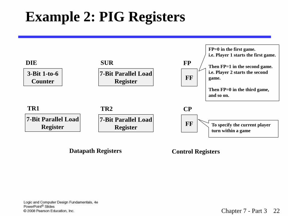
Example 2: PIG Registers
Chapter 7 - Part 3 22
3-Bit 1-to-6
Counter
DIE
7-Bit Parallel Load
Register
TR1
7-Bit Parallel Load
Register
TR2
7-Bit Parallel Load
Register
SUR
FF
CP
FF
FP
Datapath Registers Control Registers
FP=0 in the first game.
i.e. Player 1 starts the first game.
Then FP=1 in the second game.
i.e. Player 2 starts the second
game.
Then FP=0 in the third game,
and so on.
To specify the current player
turn within a game

Chapter 7 - Part 3 23
Example 2 – PIG
Specifications
PIG is a dice game which is played with a single die that has 1 to 6 dots on its six faces.
During each turn, the player rolls the die one or more times until either:
• 1 is rolled
• The player chooses to HOLD.
For each roll, the value rolled, except for a 1, is added to a subtotal for the current turn.
If a 1 is rolled, the subtotal become 0, and the player’s turn is ended.
At the end of each turn, the subtotal is added to the player’s overall total, and the play passes to the other player.
The first player to reach or exceed 100 wins.

Chapter 7 - Part 3 24
Example 2 – PIG
Specifications
Inputs: ROLL, HOLD, NEW_GAME, RESET
Outputs:
• 7-bit LED die display (DDIS)
• 7-Segment pair to display the subtotal for the current turn (SUB)
• 7-Segment pair to display the overall total for the player 1 (TP1)
• 7-Segment pair to display the overall total for the player 2 (TP2)
• Player 1 LED ON/ OFF (P1)
• Player 2 LED ON/ OFF (P2)
Registers:
• Datapath Registers:
3-bit 1-to-6 Counter (DIE)
7-bit Parallel Load Register (SUR)
7-bit Parallel Load Register (TR1)
7-bit Parallel Load Register (TR2)
• Control Registers:
Flip-Flop (FP)
Flip-Flop (CP)

Chapter 7 - Part 3 25
Example 2: PIG
Inputs, Outputs, and Registers
Symbol Name / Function Type
ROLL 1: Starts die rolling 0: Stops die rolling Control input
HOLD 1: Ends player turn 0: Continues player turn Control input
NEW_GAME 1: Stats new game 0: Continues current game Control input
RESET 1: Reset game to INIT state 0: No action Control input
DDIS 7-bit LED die display array Data output vector
SUB 14-bit 7-segment pair (a, b, c, d, e, f, g) to Turn Total display Data output vector
TP1 14-bit 7-segment pair (a, b, c, d, e, f, g) to Player 1 display Data output vector
TP2 14-bit 7-segment pair (a, b, c, d, e, f, g) to Player 2 display Data output vector
P1 1: Player 1 LED on 0: Player 1 LED off Data output
P2 1: Player 2 LED on 0: Player 2 LED off Data output
DIE Die value- Specialized counter to count 1, 2, 3, 4, 5, 6, 1, 2, 3, . . . 3- bit data register
SUR Subtotal for active player: parallel load register 7- bit data register
TR1 Overall total for player 1: parallel load register 7- bit data register
TR2 Overall total for player 2: parallel load register 7- bit data register
FP First player – flip-flop 0: Player 1, 1: Player 2 1-bit control register
CP Current player – flip-flop 0: Player 1, 1: Player 2 1-bit control register

Chapter 5 - Part 3 26
Example 2: PIG
SMD with Register Transfer Outputs
INIT
BEGIN
ROL
ROH
TEST
RESET
ONE
Defaults:
P1 = CP,
P2 = CP
WIN
DIE 000 , FP = 0
TR1 0, TR2 0, CP FP
ROLL SUR 0
ROLL
ROLL
ROLL
If (DIE = 110) DIE 001 else DIE (DIE +1)
DIE = 1
CP CP
DIE ≠ 1
SUR SUR + DIE
ROLL ROLL . HOLD
ROLL . HOLD
CP / (TR1 TR1 +SUR),
CP / (TR2 TR2 +SUR)
NEW_GAME
FP FP CP . (TR1 11000100) + CP . (TR2 11000100)
NEW_GAME CP / P1 = BLINK , CP / P2 = BLINK
CP . (TR1 < 11000100) +
CP . (TR2 < 11000100)
CP CP

Chapter 7 - Part 3 27
Example 2: PIG
Output Control/Status Table
Action or Status Control or Status
Signals
Meaning for values 1 and 0
TR1 0
TR1 TR1 + SUR
RST1
LDT1
1: Reset TR1 (Synchronous reset), 0: No action
1: Add SUR to TR1, 0: No action
TR2 0
TR2 TR2 + SUR
RST2
LDT2
1: Reset TR2 (Synchronous reset), 0: No action
1: Add SUR to TR2, 0: No action
SUR 0
SUR SUR+ DIE
RSSU
LDSU
1: Reset SUR (Synchronous reset), 0: No action
1: Add DIE to SUR, 0: No action
DIE 000
if (DIE = 110) DIE 001 else DIE (DIE +1)
RESET
ENDI
1: Reset DIE to 000 (Asynchronous reset)
1: Enable DIE to increment, 0: Hold DIE value
P1 = BLINK BP1 1: Connect P1 to BLINK, 0: Connect P1 to 1
P2 = BLINK BP2 1: Connect P2 to BLINK, 0: Connect P2 to 1
CP FP
CP CP
CPFI
LDCP
CPFI
LDCP
1: Select FP for CP
1: Load CP, 0: No action
0: Select CP for CP
1: Load CP, 0: No action
FP 0
FP FP
RESET
LDFP
Asynchronous reset
1: Invert FP, 0: Hold FP
DIE = 1
DIE ≠ 1
DIE1 1: DIE equal to 1
0: DIE not equal to 1
TR1 11000100 CP
WN
0: Select TR1 for 11000100
1: The Selected TRi 11000100
0: The Selected TRi < 11000100
TR2 11000100 CP
WN
1: Select TR2 for 11000100
1: The Selected TRi 11000100
0: The Selected TRi < 11000100

Chapter 7 - Part 3 28
Example 2: PIG
Datapath and Control Registers
DIE
RESET
ENDI
CP LDCP
CPFI MUX
FP CP/
0 1
SUR
Adder
TR1
RST1
LDT1
SUR
Adder
TR2
RST2
LDT2
DIE
Adder
SUR
RSSU
LDSU
CP MUX
TR1 TR2
0 1
Comparator
with 100
WN

Chapter 5 - Part 3 29
INIT
BEGIN
ROL
ROH
TEST
RESET
ONE
WIN
RST1 , RST2 , CPFI , LDCP
ROLL RSSU
ROLL
ROLL
ROLL
ENDI
DIE1
LDCP
DIE1
LDSU
ROLL ROLL . HOLD
ROLL . HOLD
CP / LDT1,
CP / LDT2
NEW_GAME
LDFP WN
NEW_GAME CP / BP1 , CP / BP2
WN
LDCP
Example 2: PIG SMD with Control Signal Outputs Replacing Register Transfers

Chapter 7 - Part 3 30
Example 2: PIG
Datapath and Control Registers
3-Bit 1-to-6
Counter
DIE
EN R ENDI RESET
7-Bit Ripple Carry
Adder
Parallel Load Reg.
with Sync Reset
D EN R
LDSU RSSU
7-Bit Ripple Carry
Adder
Parallel Load Reg.
with Sync Reset
D EN R
SUR
TR1
Binary-to-BCD Code
Converter
2-Digit BCD-to-7
Segment Converter
2-Digit LCD Display
7-Bit Ripple Carry
Adder
Parallel Load Reg.
with Sync Reset
D EN R
LDT2 RST2
TR2
Binary-to-BCD Code
Converter
2-Digit BCD-to-7
Segment Converter
2-Digit LCD Display
Binary-to-LED Die
Dots Decoder
Die Dot Display
D = 1 Comparator DIE1
Binary-to-BCD Code
Converter
2-Digit BCD-to-7
Segment Converter
2-Digit LCD Display
LDT1 RST1
7-Bit 2-to-1MUX D0 S CP D1
D 11000100 D WN
0000

Chapter 7 - Part 3 31
Microprogrammed Control
Microprogrammed Control — a control unit with
binary control values stored as words in memory.
Microinstructions — words in the control memory.
Microprogram — a sequence of microinstructions.
Control Memory — RAM or ROM memory holding the
microinstructions.
Writeable Control Memory — RAM Memory into
which microinstructions may be written

Chapter 7 - Part 3 32
Microprogrammed Control (continued)
Chapter 7 - Part 3 33
Terms of Use
All (or portions) of this material © 2008 by Pearson Education, Inc.
Permission is given to incorporate this material or adaptations thereof into classroom presentations and handouts to instructors in courses adopting the latest edition of Logic and Computer Design Fundamentals as the course textbook.
These materials or adaptations thereof are not to be sold or otherwise offered for consideration.
This Terms of Use slide or page is to be included within the original materials or any adaptations thereof.