Chapter 7 CORRIDOR ASSESSMENT AND IDENTIFICATION · Bus Rapid Transit System, Ahmedabad GIDB, GoG...
43
Bus Rapid Transit System, Ahmedabad GIDB, GoG 7.1. Introduction 7.2. Framework 7.3. Identification of Potential BRTS Corridors 7.4. Corridor Assessment 7.5. Corridor Selection 7.6. Summary Chapter 7 CORRIDOR ASSESSMENT AND IDENTIFICATION
Transcript of Chapter 7 CORRIDOR ASSESSMENT AND IDENTIFICATION · Bus Rapid Transit System, Ahmedabad GIDB, GoG...

Bus Rapid Transit System, Ahmedabad GIDB, GoG
7.1. Introduction
7.2. Framework
7.3. Identification of Potential BRTS Corridors
7.4. Corridor Assessment
7.5. Corridor Selection
7.6. Summary
C
hap
ter
7 C
OR
RID
OR
ASS
ESSM
ENT
AND
IDEN
TIFI
CAT
ION

Bus Rapid Transit System, Ahmedabad GIDB, GoG
AMC & AUDA 7-1 CEPT University
7. CORRIDOR ASSESSMENT AND IDENTIFICATION
7.1 Introduction
The purpose of the chapter is to identify the corridors on which opportunities for developing BRTS exist and prioritize for implementation. As discussed in the previous chapters the public transport system supply situation is very poor both in quality and quantity terms. At present there is no single corridor in Ahmedabad on which high frequency public transport services are offered and supply is constrained due to congestion. In the light of this the objective of this effort would then be to develop BRTS as a strategic intervention, which would improve public transport image, attract latent transit demand, contribute to improved transit option for people, improve air quality and help city remain a compact city.
7.2 Framework
The guiding principles are that only those corridors would be selected which:
- could accommodate BRTS treatments,
- could be Implemented quickly and inexpensively,
- could contribute to ease the problems of transport in a significant way,
- could improve mobility options of large segment of people,
- provide opportunities for improvements in land use structure/ more compact urban structure,
- Provide potentials for cost-recovery, and
- Integrates well within the overall network including other mass transit modes i.e not compete with other public transit modes.
With these as guiding principles, the process of corridor selection has been carried out in terms of three steps.
Step 1: Identification of Potential BRTS Corridors
Step 2: Carryout assessment of Corridors with regard to
1. Demand (Existing and potential)
2. Technical Feasibility to implement BRTS treatment
3. Overall System-wide Impacts
Classify corridors based on their performance on 5:1 scale and rank them.

Bus Rapid Transit System, Ahmedabad GIDB, GoG
AMC & AUDA 7-2 CEPT University
Step 3: Prioritization for exclusive BRTS treatment and for mixed operations based on:
1. Implementation considerations
2. Operational considerations
3. Integration issues
7.3 Identification of Potential BRTS Corridors
To identify the potential corridors, road network was screened with regard to three criteria.
7.3.1 DP Major Roads
All major AUDA proposed/existing Ring and Radial Roads has been considered as potential candidates for BRTS in the long list.
7.3.2 Proposals in Previous Studies
The entire proposed corridors for transit development in the previous studies have been included in the long list. The proposals were primarily from:
J
Map: 7.1a: LB Transit Proposal: Alternative 1 Map: 7.1b:LB Transit Proposal: Alternative 2
Bus Rapid Transit System, Ahmedabad GIDB, GoG
AMC & AUDA 7-3 CEPT University
NARMADA MAIN CANAL
NARMADA MAIN CANAL
0 2.5 5.0 7.5 10.0 20.0 Km
SCALE
MEHEMDABAD
DEHGAM
METRO CORRIDOR - PHASE 1METRO CORRIDOR - PHASE 2SUBURBAN RAIL PROPOSAL
NARMADA MAIN CANAL
Elevated Bus Corridor ProposalAt Grade Bus Corridor ProposalMajor Non-Prioritized Bus carrying Roads
Major Bus Terminals
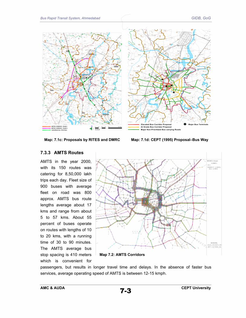
Map: 7.1c: Proposals by RITES and DMRC Map: 7.1d: CEPT (1995) Proposal–Bus Way
7.3.3 AMTS Routes
AMTS in the year 2000, with its 150 routes was catering for 8,50,000 lakh trips each day. Fleet size of 900 buses with average fleet on road was 800 approx. AMTS bus route lengths average about 17 kms and range from about 5 to 57 kms. About 55 percent of buses operate on routes with lengths of 10 to 20 kms, with a running time of 30 to 90 minutes. The AMTS average bus stop spacing is 410 meters which is convenient for passengers, but results in longer travel time and delays. In the absence of faster bus services, average operating speed of AMTS is between 12-15 kmph.
WINDOW:2121.9/2415.063677.6/3581.81
MODES:cbrpa
LINKS: all
TRANSIT LINES:ALL LINES
Map 7.2: AMTS Corridors

Bus Rapid Transit System, Ahmedabad GIDB, GoG
AMC & AUDA 7-4 CEPT University
Major corridors of public transport have been included as part of the list. It is however to be borne in mind that supply of AMTS has evolved historically and some variation in demand is possible.
Based on the above considerations, a comprehensive list of corridors has been prepared for further evaluation.
Table 7-1: List of Potential Corridors
Corridor No Name of Corridor Length of Corridor
(kms) 1 VASNA-SABARMATI – NARODA-NAROL 47.5
2 VASNA-SABARMATI 15 3 NARODA-NAROL 18
4A THALTHEJ TO KALUPUR 9.1 4B SATTADHAR TO KALUPUR 9.55 5 GHATLODIA TO VADAJ 4.92 6 SABARMATI TO SARKHEJ VIA ASHRAM RD 17.63 7 ISKCON TO KALUPUR 11.09 8 ST TO NAROL TO LAMBHA 8.44 9 ST TO JASODANAGAR CROSSROAD TO HATHIJAN 12.81 10 KALUPUR TO ODHAV 9.49 11 KALUPUR TO NARODA 10.29 12 THALTHEJ TO NAROL TO LAMBHA (UNIV ROAD) 17.15 13 SARKHEJ TO GOTA 12.45 14 PALDI TO ST VIA JAMALPUR (OPTIONAL CONNECTION) 3.25 15 ISKCON TO VASNA VIA. NEHRU NAGAR CIRCLE 6.35 16 SABARMATI – KALUPUR 8.98 17 VADAJ-GOTA 5.75
18 SHIVRANJANI-KALUPUR VIA SHREYAS, NEW BRIDGE, ST 11.57
7.4 Corridor Assessment
The assessment process is carried out in three parts:
1. Travel Demand Assessment
2. Technical Feasibility
3. System-wide Impact
The performance of each of the corridor with regard to these aspects has been discussed below:
7.4.1 Travel Demand Assessment Potential travel demand on the BRTS would consist of intra-corridor transit trips and interchange transit trips.

Bus Rapid Transit System, Ahmedabad GIDB, GoG
AMC & AUDA 7-5 CEPT University
Intra-Corridor Transit Trips: With Catchments of about < 250 mts. Distance along the corridor (abutting zone), total trips have been estimated in terms of:
Existing Bus Trips along the corridor: Bus demand has been estimated from the IPTS study travel demand. TAZs falling along the corridor have been identified for the assessment of trips along the corridor. Bus trips along the corridor were assigned on the individual corridors for the estimations of demand.
Modal Shifts in favor of BRTS: Modal split in favor of BRTS from other modes such as Bicycles, Two-wheelers and Auto rickshaws has been estimated using emme/2 based on the total trips along the corridor. The study revealed that trips having trip length less than 4 kms are less likely to shift to bus system. Hence, trips with more than 4 kms along the corridor have only been considered for demand assessment. Modal split for BRTS from other modes has been estimated using the following percentage distributions for various trips lengths and travel modes as shown in table below.
Table 7-2: Assumed Modal Split along the Corridors
Divertible Trips to BRTS Trip Length Kms
Bicycle Two Wheeler Auto Rickshaw 0-4 0% 0% 0% 4_6 20% 20% 40% 6_10 50% 60% 50% >10 70% 80% 60%
The table below summarizes the study area trips by mode and trip lengths.
Table 7-3: Divertible Trips in the Study Area /Day
Divertible Trips to BRTS Trip Length Kms
Bicycle Two Wheeler Auto Rickshaw Total % of Total
4_6 391688 799931 190893 1382512 52% 6_10 203776 576227 100056 880059 33% >10 69768 307232 32011 409011 15% Total 665232 1683390 322960 2671582 100%
% of Total 25% 63% 12% 100% The following figures present desire of the estimated trips along the various potential corridors for BRT system.

Bus Rapid Transit System, Ahmedabad GIDB, GoG
AMC & AUDA 7-6 CEPT University
WINDOW:1595.7/2560.633145.7/ 3723.1
SCALE: 1000
PLOT MATRIX:mf230:alltrp
LINKS: all
CONSTRAINT: mf230: alltrpLOWER: 0UPPER: 250EXCLUDE
SUBMATRIX: 26 ORIGINS 27 DESTINS.
WINDOW:1889.7/2621.883458.1/3798.24
SCALE: 1000
PLOT MATRIX:mf230:alltrp
LINKS: all
CONSTRAINT: mf230: alltrpLOWER: 0UPPER: 250EXCLUDE
SUBMATRIX: 34 ORIGINS 34 DESTINS.
WINDOW: 2086/2301.26 4321/3977.54
SCALE: 1000
PLOT MATRIX:mf230:alltrp
LINKS: all
CONSTRAINT: mf230: alltrpLOWER: 0UPPER: 250EXCLUDE
SUBMATRIX: 35 ORIGINS 35 DESTINS.
WINDOW:1729.6/2399.133535.7/3753.65
SCALE: 1000
PLOT MATRIX:mf230:alltrp
LINKS: all
CONSTRAINT: mf230: alltrpLOWER: 0UPPER: 250EXCLUDE
SUBMATRIX: 41 ORIGINS 41 DESTINS.
WINDOW:
1729.6/2399.133535.7/3753.65
SCALE: 1000
PLOT MATRIX:mf230:alltrp
LINKS: all
CONSTRAINT: mf230: alltrpLOWER: 0UPPER: 250EXCLUDE
SUBMATRIX: 41 ORIGINS 41 DESTINS.
WINDOW:1724.6/2919.662873.8/3781.53
SCALE: 1000
PLOT MATRIX:mf230:alltrp
LINKS: all
CONSTRAINT: mf230: alltrpLOWER: 0UPPER: 250EXCLUDE
SUBMATRIX: 33 ORIGINS 33 DESTINS.
WINDOW:2139.9/2323.983129.7/3066.34
SCALE: 1000
PLOT MATRIX:mf230:alltrp
LINKS: all
CONSTRAINT: mf230: alltrpLOWER: 0UPPER: 250EXCLUDE
SUBMATRIX: 19 ORIGINS 19 DESTINS.
WINDOW:
1729.1/2746.743069.1/3751.74
SCALE: 1000
PLOT MATRIX:mf230:alltrp
LINKS: all
CONSTRAINT: mf230: alltrpLOWER: 0UPPER: 250EXCLUDE
SUBMATRIX: 45 ORIGINS 45 DESTINS.
Map 7.3 Intra-corridor passenger trips: Desire Line Diagrams for select corridors
The table below presents estimated intra corridor potential BRT trips (including modal shift) for the year 2000.
Table 7-4: Potential BRT Trips
Trips/day along the corridor by Other Modes > 4 km trip length
Estimated Modal Shift to
BRTS from Other Modes
Sl. No Corridor Name
Total Existing Bus Trips along the Corridor
TAZ’s Cycle TW Auto Total Trips/ day
% of Trips
Total BRT Trips (2000)
1 VASNA-SABARMATI – NARODA-NAROL 45,889 43,251 62,591 22,407 128,249 28,135 22% 74,024
2 VASNA-SABARMATI 47476 14635 27943 6760 49338 20047 41% 67,523
3 NARODA-NAROL 31584 15528 12504 9546 37578 14957 40% 46,541
4A THALTHEJ TO Kalupur 25,897 5,432 15,733 3,623 24,788 11,215 45% 37,112
4B SATTADHAR TO KALUPUR 28,620 6,782 16,763 3,490 27,035 12,374 46% 40,994
5 GHATLODIA TO VADAJ 12,438 2,926 5,174 302 8,402 2,914 35% 15,352

Bus Rapid Transit System, Ahmedabad GIDB, GoG
AMC & AUDA 7-7 CEPT University
Trips/day along the corridor by Other Modes > 4 km trip length
Estimated Modal Shift to
BRTS from Other Modes
Sl. No Corridor Name
Total Existing Bus Trips along the Corridor
TAZ’s Cycle TW Auto Total Trips/ day
% of Trips
Total BRT Trips (2000)
6 SABARMATI TO SARKHEJ 32,239 7,922 13,977 3,939 25,838 6,813 39% 42,435
7 ISKON TO KALUPUR 31,173 4,698 26,218 4,350 35,266 15,809 45% 46,982
8 ST TO NAROL TO LAMBHA 13,826 5,279 3,176 2,421 10,876 3,325 31% 17,151
9 ST TO JASODANAGAR CROSSROAD TO HATHIJAN 17,309 7,692 5,716 3,491 16,899 8,226 49% 25,535
10 KALUPUR TO ODHAV 16,253 9,634 5,332 1,399 16,365 6,169 38% 22,422
11 KALUPUR TO NARODA 20,955 13,440 7,440 5,131 26,011 9,944 38% 30,899
12 THALTHEJ TO NAROL TO LAMBHA (UNIV ROAD) 45,166 8,953 25,023 8,264 42,240 16,306 39% 61,472
13 SARKHEJ TO GOTA 21,370 3,806 7,571 4,333 15,710 6,399 41% 27,769
14 PALDI TO ST CONNECTION VIA JAMALPUR (OPTIONAL) 7,712 1,936 624 1,295 3,855 1,166 30% 8,878
15 ISKCON TO VASNA VIA. NEHRU NAGAR CIRCLE 20,398 4,678 11,560 3,881 20,119 7,587 38% 27,985
16 SABARMATI – KALUPUR 21,291 6,764 13,346 3,080 23,190 9,942 43% 31,233
17 VADAJ-GOTA 17939 5522 7557 567 13646 4601 34% 22,540
18 ISKCON-KALUPUR-VIA NEHRUNAGAR-SHREYAS-PROPOSED BRIDGE (VASNA) 31716 7160 17968 5566 30694 12667 41% 44,383
(B) Interchange Trips with Transfer Facility (AMTS + BRTS)
Assessment of travel demand with feeder/mixed corridors and AMTS services has been performed using emme/2 model transit assignment procedure. In the model, the user preference for choosing services depends up on the frequency of services and travel speed. All existing AMTS and proposed BRTS corridors were modeled.
© Total Potential BRT Trips for future Years and Ranking
The total trips estimated for the future years includes intra corridor as well as interchange trips. The trip density has been estimated to bring the demand at one common scale. Further to this, trip density was classified into five categories as ‘very high’, ‘high’, ‘moderate’, ‘low’, and ‘very low’. Each of these were given a score on the scale of 5:1. The combined score for all the three time periods (2000, 2007, 2015) have been tabulated for final ranking.
Table 7-5: Potential BRT Trips on Various Corridors and Ranking
Total BRT Trips/day Trip Density
(trips per day per km) Sl. No Corridor Name Length
(Km) 2000 2007 2015 2000 2007 2015
Score Ranking
1 VASNA-SABARMATI – NARODA-NAROL 47.3 74024 201893 236757 1565 4268 5005 6 7
2 VASNA-SABARMATI 15 67523 127330 151614 4502 8489 10108 14 1
3 NARODA-NAROL 18 46541 74563 85143 2586 4142 4730 7 6
4A THALTHEJ TO KALUPUR 9.1 37112 71782 80810 4078 7888 8880 13 2
4B SATTADHAR TO KALUPUR 9.55 40994 69798 77421 4293 7309 8107 13 2
5 GHATLODIA TO VADAJ 4.92 15352 13628 15192 3120 2770 3088 7 6
6 SABARMATI TO SARKHEJ 17.63 42435 94905 105118 2215 5383 5962 8 5

Bus Rapid Transit System, Ahmedabad GIDB, GoG
AMC & AUDA 7-8 CEPT University
Total BRT Trips/day Trip Density (trips per day per km)
7 ISKON TO KALUPUR 11.09 46982 94190 104111 4236 8493 9388 13 2
8 ST TO NAROL TO LAMBHA 8.44 17151 32154 37446 2032 3810 4437 6 7
9 ST TO JASODANAGAR CROSSROAD TO HATHIJAN 12.81 25535 54905 61196 1993 4286 4777 5 8
10 KALUPUR TO ODHAV 9.49 22422 36382 40381 2363 3834 4255 6 7
11 KALUPUR TO NARODA 10.29 30899 50023 54667 3003 4861 5313 9 4
12 THALTHEJ TO NAROL TO LAMBHA (UNIV ROAD) 17.15 61472 50698 60754 3584 2956 3543 7 6
13 SARKHEJ TO GOTA 12.45 27769 27907 37219 2230 2242 2989 4 9
14 PALDI TO ST CONNECTION VIA JAMALPUR (OPTIONAL) 3.25 8878 12412 13263 2732 3819 4081 7 6
15 ISKCON TO VASNA VIA. NEHRU NAGAR CIRCLE 6.35 27985 12829 15870 4407 2020 2499 7 6
16 SABARMATI – KALUPUR 8.98 31233 66400 72635 3478 7394 8089 12 3
17 VADAJ-GOTA 5.75 22540 19648 22479 3920 3417 3909 8 5
18 ISKCON-KALUPUR-VIA NEHRUNAGAR-SHREYAS-PROPOSED BRIDGE (VASNA) 11.57 44383 54197 61069 3836 4684 5278 9 4
7.4.2 Technical Feasibility to implement BRTS treatment
Technical feasibility to implement BRTS treatment includes Road Width, Corridor/Road Length, number and nature of bottlenecks and environmental and social issues.
Road Width: It is possible that BRTS treatment can be included on any road width. However, narrow roads would mean altering the traffic pattern completely through introduction of no entry, one-way system or reserving entire road for bus and slow moving vehicles. These measures may be required in extreme situations and but likely to receive very limited public support.
To be able to provide two exclusive lanes for BRTS and at the same time provide 4 lanes (narrow) for vehicles and bicycles and footpath a critical minimum of 27 meters width is required. However, according to the team suggested critical minimum width for BRTS treatment is 30 meters. Any corridor with lesser width would mean either BRTS runs as mixed operations on those stretches or road widening or road closure for certain vehicles would be required. At this stage implementation of BRTS exclusive lanes on corridor with inadequate road-width would receive less priority.
Corridor Length: From the point of view of operations longer corridors are beneficial in many ways. They are:
i. Reduction in turn-around time leading to increased vehicle utilization
ii. Size of operations increase
iii. Large size operations mean mobility improvement to many
iv. Extensions to the network possible
v. Flexible Operations
vi. Possible to operate BRTS as independent operation

Bus Rapid Transit System, Ahmedabad GIDB, GoG
AMC & AUDA 7-9 CEPT University
a. Closed System Operations become viable
b. Private participation
c. Monitoring and regulating of services become less complex
Bottlenecks: In any network the bottlenecks such as frequent junctions, existence of level crossings, underpasses and flyover with 2/4 lanes would become problem areas. The details of these on each of the corridor have been presented below.
Environmental and Social Issues: Environmental aspects such as effects on air quality, issue of tree preservation and encroachment removal, road widening would have a bearing on the implementation of the project. As the proposed corridors under consideration utilize existing ROW, the project teams do not anticipate any major environmental or social issues. A detailed analysis of the same is proposed during DPR stage.
Table 7-6: Bottlenecks on the Corridors
1 VASNA-SABARMATI - NARODA-NAROL 26.5 8.2 7.0 3.9 1.3 0.4 16 34 2 31 52 1 1 3 6 5 1
2 VASNA-SABARMATI 2.1 12.9 0.0 0.0 0.0 0.0 8 16 0 15 24 0 1 2 3 3 3
3 NARODA-NAROL 18.0 0.0 0.0 0.0 0.0 0.0 6 15 1 11 22 1 0 1 4 5 1
4A THALTHEJ TO KALUPUR 0.0 0.0 2.1 4.0 1.0 0.4 2 13 2 13 17 0 1 0 2 1 5
4B SATTADHAR TO KALUPUR 0.0 0.0 2.1 5.7 1.3 0.4 2 10 5 14 17 1 1 0 1 1 5
5 GHATLODIA TO VADAJ 0.0 0.0 0.0 3.9 1.3 0.0 3 5 2 6 10 1 0 0 1 2 2
6 SABARMATI TO SARKHEJ VIA ASHRAM RD 3.3 3.8 2.5 7.6 0.7 0.0 7 16 2 19 25 1 0 1 1 3 3
7 ISKCON TO KALUPUR 0.5 2.7 0.0 7.2 0.7 0.0 3 17 1 17 21 0 1 0 2 1 5
8 ST TO NAROL TO LAMBHA 3.1 0.0 0.0 5.4 0.0 0.0 2 11 1 7 14 0 0 0 0 4 2
9 ST TO JASODANAGAR CROSSROAD TO HATHIJAN 7.6 0.0 0.0 3.1 2.2 0.0 3 10 2 10 15 1 0 0 0 4 2
10 KALUPUR TO ODHAV 0.0 0.0 0.0 9.5 0.0 0.0 2 8 0 7 10 0 0 1 0 4 2
11 KALUPUR TO NARODA 4.5 0.0 0.0 5.8 0.0 0.0 3 4 1 4 8 0 0 1 0 5 1
12 THALTHEJ TO NAROL TO LAMBHA (UNIV ROAD) 3.1 0.0 10.8 3.3 0.0 0.0 6 21 0 14 27 0 0 1 2 4 2
13 SARKHEJ TO GOTA 12.5 0.0 0.0 0.0 0.0 0.0 2 10 0 7 12 0 0 1 2 5 1
14 PALDI TO ST VIA JAMALPUR (OPTIONAL CONNECTION) 0.0 0.0 0.0 3.3 0.0 0.0 1 3 1 5 5 0 0 0 0 1 5
15 ISKCON TO VASNA VIA. NEHRU NAGAR CIRCLE 0.5 3.1 2.4 0.3 0.0 0.0 0 9 0 6 9 0 0 1 2 3 3
16 SABARMATI - KALUPUR 2.6 0.4 2.1 2.3 0.7 0.4 3 11 0 12 14 0 0 1 0 2 2
17 VADAJ-GOTA 0 0 0 0 0 0 3 1 4 6 1 0 0 5 1
18 SHIVRANJANI-KALUPUR VIA SHREYAS, NEW BRIDGE, ST 0.5 0.2 5.4 5.5 0.0 0.0 1 15 2 13 18 0 0 1 1 3 3
Bottlenecks
Score Rank
Leve
l Cro
ssin
gs
Und
erpa
ss
Flyo
ver/R
oB
Flyo
ver/R
oB
(Pro
pose
d)
60m
40m
30-4
0m
30m
20-3
0m
>20m
3-ar
m
4-ar
m
Mul
tipleC
orrid
or N
o
Name of Corridor
Road Length with RoW Junctions
Maj
or J
unct
ions
Tota
l Jun
ctio
ns
Detail corridor profile is presented in Annexure 7.1.
7.4.3 Systemwide Impact
Major effort of this kind intending to develop BRTS must aim to achieving the following:

Bus Rapid Transit System, Ahmedabad GIDB, GoG
AMC & AUDA 7-10 CEPT University
1. Relieve congestion
2. Improve safety
3. Maximize the rider-ship; present and the potential
4. Have citywide impacts
5. Provide opportunities for Transit-Oriented Development/ Promote Compact City
6. Integrate with other modes and thus provide greater accessibility to amenities and opportunities for mobility
7. Serve the needs of the poor
Of course bus by nature, with use of CNG would ameliorate negative environmental impacts.
These factors have been broadly analyzed as system-wide impacts in terms of volume capacity ratio, accident ratio, population coverage, total transit trips and integration aspects with major facilities and amenities. The situation and results have been summarized below.
Table 7-7: System-wide Impacts
7.5 Corridor Selection
The performance of corridors with regard to three broad criteria has been presented table 7.9.
The circular corridor VASNA-SABARMATI – NARODA-NAROL emerges as top ranking corridor. While the corridor scores high on system-wide impacts and technical feasibility, density of travel demand is not high. This is mainly because east-west section has very little
1 VASNA-SABARMATI - NARODA-NAROL 7350 3.45 1713976 67 5 5 5 8 2 3 1 1 1 12 VASNA-SABARMATI 3354 0 379303 59.1 2 3 3 0 2 0 1 0 1 93 NARODA-NAROL 6221 2.6 807015 69.2 2 2 1 2 0 1 0 1 0 2
4A THALTHEJ TO KALUPUR 6405 1.1 319187 51 1 2 6 4 2 1 1 1 1 64B SATTADHAR TO KALUPUR 6405 1.1 327888 63 1 2 4 2 0 1 1 1 1 55 GHATLODIA TO VADAJ 2809 0.9 309360 54 0 2 0 0 0 0 0 0 0 126 SABARMATI TO SARKHEJ VIA ASHRAM RD 6012 4.7 433826 49 2 2 6 3 1 1 0 1 2 37 ISKCON TO KALUPUR 8190 0.31 316087 61 2 2 3 4 1 4 1 0 1 48 ST TO NAROL TO LAMBHA 3586 1.6 281244 77 3 0 1 0 0 0 0 0 0 79 ST TO JASODANAGAR CROSSROAD TO HATHIJAN 4861 1.6 466781 81 2 0 1 0 0 0 0 0 0 8
10 KALUPUR TO ODHAV 7913 0.4 364771 83 1 2 0 0 1 0 1 1 1 511 KALUPUR TO NARODA 2509 0 676590 80 2 2 0 1 1 0 1 0 1 712 THALTHEJ TO NAROL TO LAMBHA (UNIV ROAD) 3586 1.6 496002 52 2 1 6 0 2 0 0 1 0 813 SARKHEJ TO GOTA 4004 0 248150 53 0 0 0 1 0 3 0 0 1 1114 PALDI TO ST VIA JAMALPUR (OPTIONAL CONNECTION) 3604 0 225777 74 1 0 1 0 0 0 1 0 0 915 ISKCON TO VASNA VIA. NEHRU NAGAR CIRCLE 1741 0 274616 51 0 1 1 1 0 3 0 0 0 1316 SABARMATI - KALUPUR 5458 1 325595 78 3 1 0 0 0 1 1 1 1 617 VADAJ-GOTA 2809 0 324333 64 1 1 0 0 0 0 0 0 0 1018 SHIVRANJANI-KALUPUR VIA SHREYAS, NEW BRIDGE, ST 8190 1.6 408688 63 3 2 1 0 0 0 1 0 0 5
Sys
tem
Im
pact
Rank
Her
itage
Sta
dium
s
Pub
lic In
stitu
tes
Hos
pita
lsP
ublic
S
pace
s/G
arde
ns/
Ent
erta
inm
ent
Who
lesa
le M
arke
ts
% E
WS
& L
IG
Reg
iona
l Tra
nspo
rt Te
rmin
als(
Rai
lway
S
t and
ST
Dep
ot)
City
Tra
nspo
rt te
rmin
als(
AM
TS)
Uni
vers
ity/C
olle
ges
Pea
k H
our T
raffi
c (P
CU
's)
Fata
l Acc
iden
ts
Den
sity
(200
2) F
atal
A
ccid
ents
/Km
Pop
ulat
ion
Cor
ridor
No
Nam
e of
Cor
rido r

Bus Rapid Transit System, Ahmedabad GIDB, GoG
AMC & AUDA 7-11 CEPT University
travel potential (air port, water works etc.,) Innovative route structuring strategies can enhance the travel demand. These are being analyzed further.
The north-south corridor SABARMATI TO SARKHEJ VIA ASHRAM RD and THALTHEJ TO KALUPUR east-west corridors got second rank. Both the corridors have been included as Metro corridors. Hence these have not been included for Exclusive Bus Lane treatment. However BRTS mixed services should operate on these til the time Metro becomes operational. In fact this would build traffic for metro in the long run. The corridor Naroda-Narol also got second rank.
The corridor VASNA-SABARMATI along 132 feet ring road emerged as major transit demand corridor. The corridor envisaged as part of circular corridor, together with ISKCON TO KALUPUR and SATTADHAR TO KALUPUR ranked number three in the overall ranking.
SHIVRANJANI-KALUPUR VIA SHREYAS, NEW BRIDGE, ST got fourth rank. The fifth ranked corridor Naroda – Narol competes with regional rail and hence not considered. Thaltej to Lamba with sixth rank largely mixes with other options and hence not considered further. To balance the overall transit network the seventh ranked Kalupur to Odhav (Sonini Chali) has been recommended for inclusion in the list of corridors for exclusive lane treatment. An extension to Maninagar, a major railway station has also been recommended.
7.5.1 BRTS Corridor Phasing
In addition to the rakings, in this decision process, following principles have been followed.
1. Metro Phase-1 Proposals (2 Corridors) have been taken as given.
2. Similarly Regional Rail Proposals are taken as given
3. The corridor on which Metro is proposed during phase-1 BRTS exclusive lane is not proposed. However it is recommended that on these corridors AMTS-BRTS mixed services should be operated. These services are expected to maintain certain quality – quantity standards.
4. On the same line exclusive bus lanes would not be implemented on corridors parallel to regional rail proposal only mixed services should be provided till the rail project materializes.

Bus Rapid Transit System, Ahmedabad GIDB, GoG
AMC & AUDA 7-12 CEPT University
Table 7-8: Final Ranking Of Corridors and Recommendations
Rank as per respective considerations Corridor
No. Name of Corridor Transit
DemandTechnical Feasibility
System Impact
Cumulative Rank (equal
weight)
Final Rank Recommendations
1 VASNA-SABARMATI – NARODA-NAROL 7 1 1 9 1 Exclusive BRTS Corridor and
Closed System Operation
2 VASNA-SABARMATI 1 3 9 13 4 Part of C- 1
3 NARODA-NAROL 6 1 2 9 1 Part of C-1
4A THALTHEJ TO KALUPUR 2 5 6 13 4 METRO Proposed – 1st Phase. AMTS-BRTS Mixed Service
4B SATTADHAR TO KALUPUR 2 5 5 12 3 Parallel to Metro Line AMTS-BRTS Mixed Service
5 GHATLODIA TO VADAJ 6 2 12 20 8 No BRTS
6 SABARMATI TO SARKHEJ VIA ASHRAM RD 5 3 3 11 2 METRO Proposed – 1st Phase.
AMTS-BRTS Mixed Service
7 ISKCON TO KALUPUR 2 5 4 11 2 Partly included in C-1 Phase-2 AMTS-BRTS Mixed Service
8 ST TO NAROL TO LAMBHA 7 2 7 16 6 Part of several corridors- no specific suggestion.
9 ST TO JASODANAGAR CROSSROAD TO HATHIJAN 8 2 8 18 7 Parallel to Regional Rail Line
AMTS-BRTS Mixed Service
10 KALUPUR TO ODHAV 7 2 5 14 5 Exclusive Bus Lane Phase-1.b AMTS-BRTS Mixed Service
11 KALUPUR TO NARODA 4 1 7 12 3 Parallel to Regional Rail Line AMTS-BRTS Mixed Service
12 THALTHEJ TO NAROL TO LAMBHA (UNIV ROAD) 6 2 8 16 6 Part of other corridors
13 SARKHEJ TO GOTA 9 1 11 21 9 Phase-3
14 PALDI TO ST VIA JAMALPUR (OPTIONAL CONNECTION)
6 5 9 20 8 Part of C1 AMTS-BRTS Mixed Service
15 ISKCON TO VASNA VIA. NEHRU NAGAR CIRCLE 6 3 13 22 10 Part of C1
AMTS-BRTS Mixed Service
16 SABARMATI – KALUPUR 3 2 6 11 4 AMTS-BRTS Mixed Service
17 VADAJ-GOTA 5 1 10 16 8 Phase-2
18 SHIVRANJANI-KALUPUR VIA SHREYAS, NEW BRIDGE, ST
4 3 5 12 4 Exclusive Bus lane (part C1) & part phase-1 b
7.5.2 BRTS and AMTS Operations in Ahmedabad
The fleet requirement to achieve the desired level of public transport patronize has been presented in chapter 6 and have also been summarized in Chapter 8. It is envisaged that there will be three types of bus services in Ahmedabad in future:
1. BRTS Closed System Operations
On all the corridors with exclusive corridor Closed System operations are recommended. On this corridor only BRTS buses will provide transit service.
2. AMTS-BRTS Mixed Operations
Bus Rapid Transit System, Ahmedabad GIDB, GoG
AMC & AUDA 7-13 CEPT University
On rest of the corridors identified above, AMTS-BRTS mixed operations will be providing service. Here both system will run in a competitive environment. It is likely that private operators under AMTS may be asked to operate on these routes.
3. AMTS Operations
The AMTS will continue to own and run its own fleet. It is generally suggested that at least 25% of total PT fleet under AMTS ownership and operate on all routes other than BRTS Exclusive Corridor. (Indicative)
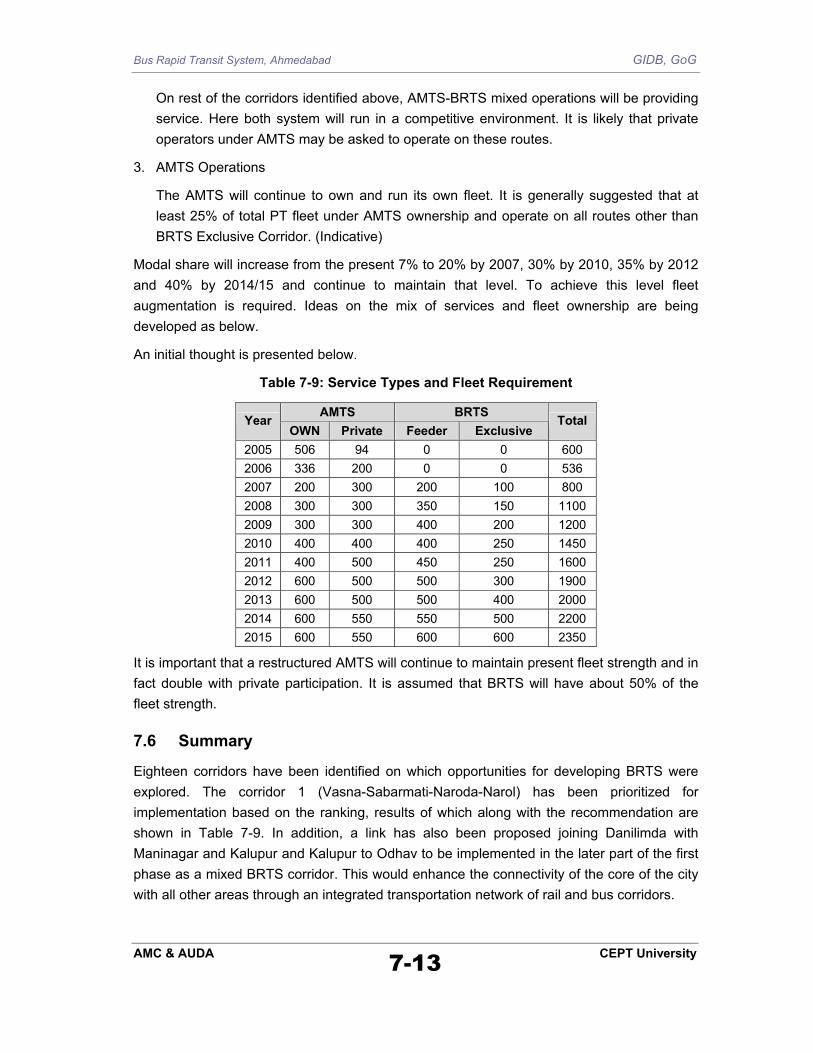
Modal share will increase from the present 7% to 20% by 2007, 30% by 2010, 35% by 2012 and 40% by 2014/15 and continue to maintain that level. To achieve this level fleet augmentation is required. Ideas on the mix of services and fleet ownership are being developed as below.
An initial thought is presented below.
Table 7-9: Service Types and Fleet Requirement
AMTS BRTS Year OWN Private Feeder Exclusive
Total
2005 506 94 0 0 600 2006 336 200 0 0 536 2007 200 300 200 100 800 2008 300 300 350 150 1100 2009 300 300 400 200 1200 2010 400 400 400 250 1450 2011 400 500 450 250 1600 2012 600 500 500 300 1900 2013 600 500 500 400 2000 2014 600 550 550 500 2200 2015 600 550 600 600 2350
It is important that a restructured AMTS will continue to maintain present fleet strength and in fact double with private participation. It is assumed that BRTS will have about 50% of the fleet strength.
7.6 Summary
Eighteen corridors have been identified on which opportunities for developing BRTS were explored. The corridor 1 (Vasna-Sabarmati-Naroda-Narol) has been prioritized for implementation based on the ranking, results of which along with the recommendation are shown in Table 7-9. In addition, a link has also been proposed joining Danilimda with Maninagar and Kalupur and Kalupur to Odhav to be implemented in the later part of the first phase as a mixed BRTS corridor. This would enhance the connectivity of the core of the city with all other areas through an integrated transportation network of rail and bus corridors.

Bus Rapid Transit System, Ahmedabad GIDB, GoG
AMC & AUDA 7-14 CEPT University
Map 7.4 BRTS Network

Bus Rapid Transit System, Ahmedabad GIDB, GoG
AMC & AUDA 7-15 CEPT University
Map 7.5 BRTS Phasing and Integration

Bus Rapid Transit System, Ahmedabad GIDB, GoG
AMC & AUDA 7-16 CEPT University
Map 7. 6 BRTS Transit Line Diagram

Bus Rapid Transit System, Ahmedabad GIDB, GoG
8.1. Introduction
8.2. Policy Issues
8.3. Design Consideration
8.4. Operational Issues
8.5. Evolving Alternative Cross Sections
8.6. Plan/Profile for a Typical Section
8.7. Block Cost Estimates
8.8. Construction Sequence
8.9. Summary
C
hap
ter
8 T
HE
BU
S R
APID
TR
ANSI
T SY
STEM
DES
IGN

Bus Rapid Transit System, Ahmedabad GIDB, GoG
AMC & AUDA 8-1 CEPT University
8. THE BUS RAPID TRANSIT SYSTEM DESIGN
8.1 Introduction
The proposed Bus Rapid Transit System will be a high quality, ultra-modern and passenger oriented rapid transit system to deliver fast, comfortable, economical and eco-friendly mobility to urban dwellers. By introducing the BRT system, the overall traffic flow will improve as significant shift from privatized modes towards BRT system is expected. Having identified BRT system corridors, this chapter discusses the policy and planning issues related with the development of BRT system as a whole. This chapter further discusses design and operational issues of the BRT System. At the end, based on the design recommendations, block cost estimates has been presented. It is recommended to develop a BRTS of around 50 km in phase-I comprising six road sections of varying length and ROW having dedicated road width for BRT. In addition there would be corridors on which BRT buses will run with other service (AMTS) acting as feeder service to the primary corridor.
8.2 Policy Issues
8.2.1 Median versus Side Lanes
Exclusive bus lanes are proposed to be mostly at grade, segregated from the existing volume of traffic by means of a physical separation. These exclusive bus lanes could be strategically placed either at the centre of the road (Median Bus lanes) or at the side (Side Bus lanes). Given below is a comparison of both types of bus ways:
SIDE LANE MEDIAN LANE Compatible with conventional bus door configuration on curb side (left side).
Easy to integrate bus flow with other flow at intersection
Easier accessibility from the pedestrian pathway.
Optimum road width for both direction movements.
Total road width occupied for bus lane is double.
Infrastructure created can be utilized even if BRTS withdrawn.
Capacity will remain under utilized. Traditional bus door configuration on left side of travel can be retained by providing bus stops on left side.
Cost intensive treatment at junctions would have to be carried out as free left turn for regular traffic would be cut off.
Slight diversion to other traffic when a bulge is provided to accommodate the bus stops.
Example: Quito Examples: Bogotá, Curituba, Cambridge
Experiences worldwide suggest having BRT system in the central verge (median lane) of the roadway is better option than curb lanes. For the city of Ahmedabad, given the constraints of road widths, encroachments, cattle menace and traffic disorder the median lane option for BRT is recommended.

Bus Rapid Transit System, Ahmedabad GIDB, GoG
AMC & AUDA 8-2 CEPT University
8.2.2 Open versus Closed System
Open System: BRT system lane is kept open for all existing bus operators. The benefit of dedicated infrastructure is distributed to all operators.
Closed System: BRT system lane is restricted only for BRT buses. BRT operators remain the only beneficiaries and hence responsible for efficiency and maintenance.
It is recommended to have a “Closed System” on the corridors where exclusive BRT system lane is proposed to be developed. The exclusive BRT lanes must be physically separated from the rest of the traffic by a physical barrier. However, considering the criticality of services, it is recommended that Fire Brigade and Ambulances will be allowed on the BRTS Lane.
8.2.3 Exclusive/Dedicated versus Mixed Corridor
The presence of other bus service such as AMTS in the mixed traffic lanes would not only undermine the rider ship and hence profitability of the new system (BRT) under consideration; it will also congest the already reduced lanes for other traffic. Therefore it is recommended that the BRT corridors having dedicated BRT system lanes shall have only BRT system bus service running. No other service shall be allowed to compete with BRT system. However, BRTS buses will share other feeder routes with AMTS where there is no provision of dedicated bus lanes. Such a facility is referred as mixed corridor. BRT system buses, other buses and other traffic will share the available right of way.
8.2.4 Land Ownership of the corridor
One of the corridors under consideration for BRT system is part of National Highway 8 currently under the ownership of the National Highway Authority of India (NHAI). This highway may be handed over to Ahmedabad Municipal Corporation (AMC) once bypass to this is open to the traffic. Effort to develop BRT system on this corridor therefore should be coordinated with NHAI.
8.2.5 Bus Technology/Size Issue
The following are the vehicle types which can be used in the proposed BRT system with varying capacity.
Table 8-1: Vehicle Capacity
Vehicle type Typical Number of Passenger Typical Vehicle Length (m)
Vans 10-16 3 Mini Buses 25-35 6
Standard Buses (low floor) 60-80 12
Articulated Buses 120-170 18 Bi-Articulated Buss 240-270 24

Bus Rapid Transit System, Ahmedabad GIDB, GoG
AMC & AUDA 8-3 CEPT University
However, to start with, we recommend using Standard buses having capacity between 60 and 70 passengers at a time.
The buses operating in the BRT system could be Indian buses, manufactured in India and eventually assembled in Ahmedabad. Clean bus technology to reduce emissions is essential. In this regard, we recommend exploring possibilities of having standard buses with required modification in floor height, seating arrangements etc. running on Compressed Natural Gas (CNG).
8.2.6 Advance Technology
The use of advanced technologies (or Intelligent Transportation Systems) to improve customer convenience, speed, reliability, and safety will be explored. Examples include systems that provide traffic signal preference for buses at intersections and cross streets, as well as Global Positioning Systems (GPS) to provide passenger information including real-time bus arrival information.
8.2.7 Fare Policy
Fare structure for the BRT system will be as competitive as possible.
8.3 Design Consideration
8.3.1 Geometric Design
The geometric design standards set for the project have been given in the below. Sr. No. Description Design Standards
ROW 1. ROW 40 - 60m 2. Set back between building line & road boundary 3 - 6m
Design Speed 3. Design Speed 80 kmph
Geometric Design 4. Cross-sectional elements
i.Lane widths a. Median Bus Lanes b. Carriageway c. Parking For Trucks d. Parking For Cars e. Service Lane f. Cycle Path
7.0m 7.0m 3.0m
2.25m 6.0m
2.5/2.0m

Bus Rapid Transit System, Ahmedabad GIDB, GoG
AMC & AUDA 8-4 CEPT University
Sr. No. Description Design Standards
g. Pedestrian Pathway ii.Cross Slope
a. Median Bus Lanes b. Carriageway c. Parking For Trucks d. Parking e. Service Lane f. Cycle Path g. Pedestrian Pathway
2.0m
2.0% 2.0% 2.0% 1.5% 1.5% 1.5% 1.5%
5. Shyness strip @ Median side 0.25m 6. Safe Stopping Sight distance 120m
7. Horizontal Alignment i.Requiring no super elevation ii.Desirable requiring 4% super elevation iii.Absolute minimum requiring 7% super elevation
1400m
265m 230m
8. Vertical Alignment Minimum distance between PVI Minimum length of vertical curve Minimum “K” value For – Sag curve For – Crest curve
150m 50m
30 35
9. Gradient Maximum Desirable Minimum In kerbed sections Desirable Minimum Absolute Minimum Desirable Maximum for Pedestrian Ramps Desirable Maximum for Cycle tracks
4% 2% 0.5%
0.5% 0.3% 10% 3%
10. Maximum grade change not requiring a vertical curve 0.6% 11. Minimum vertical clearance to road bridge over road 5.5m 12. Minimum vertical clearance to road bridge over rail 6.75m 13.
Super elevation Maximum Desirable
7% 4%
14. Rate of change of super elevation 1 in 150 15. Median
i.Width of Median / Bus Shelter (raised) ii.Transition in Median
2.5m
1 in 15 to 1 in 20 Pavement Design
16. i.For BRT Bus lanes & Carriageway a. Bituminous Concrete (BC) or AC b. Dense Graded Bituminous Macadam (DBM) c. Wet Mix Macadam (WMM) d. Granular Subbase (GSB) e. Subgrade (SG)
Thickness 40mm 160mm 300mm 420mm
500mm (min)
ii.For Service lane Thickness

Bus Rapid Transit System, Ahmedabad GIDB, GoG
AMC & AUDA 8-5 CEPT University
Sr. No. Description Design Standards
a. Bituminous Concrete (BC) or AC b. Dense Graded Bituminous Macadam (DBM) c. Wet Mix Macadam (WMM) d. Granular Subbase (GSB) e. Subgrade (SG)
40mm 60mm 200mm 400mm
500mm (min) Intersection Design
17. Intersections i.Length of storage lane (including 50m taper) for right
turning 130m
ii.Minimum length of acceleration lane (including 80m taper) 180m iii.Minimum length of deceleration lane (including 80m taper) 120m iv.Maximum radius for left turn 30m v.Minimum radius for right turn 15m vi.Width of turning lane (inner radius of 30 m) 5.5m vii.Rate of taper (minimum) 1 in 15 viii.Minimum size of channelising island 4.5sqm ix.Offset of island from vehicle path 0.3 – 0.6m x.Desirable angle of intersection arm 60 – 90 degrees
Drainage Design 18. Drain
i.Minimum longitudinal gradient ii.Minimum width of drain iii.Minimum diameter of drain
0.3% 0.25m 0.45m
19. Manholes i. Spacing
ii.Minimum inside dimension iii.Minimum allowable width (in case of shallow manholes
upto 1.40m) iv.Opening for entry
10 – 20m 120cm X 90cm
75cm
50cm clear Safety Measures
20. Traffic signals IRC : 93 – 1985 and better experiences
21. Pedestrian crossings & pathways IRC : 103 – 1988 and better experiences
Road Furniture 22. Road signage IRC : 67 – 1977 and better
experiences 23. Pavement markings IRC : 35 – 1997 and better
experiences 24. Delineators IRC : 79 - 1981 and better
experiences Utilities
25. Maximum depth of laying for Utility Lines i.Trunk sewer line
ii.Water supply line a. Service line b. Trunk line
iii.Electric cable a. LT cable b. HT cable
2 – 6m
0.6 – 1m 1 – 1.5m
0.6 – 1m 1.5 – 2m

Bus Rapid Transit System, Ahmedabad GIDB, GoG
AMC & AUDA 8-6 CEPT University
Sr. No. Description Design Standards
iv.Telecommunication cable a. Directly laid b. Laid in ducts
v.Gas mains & lines
0.6 – 1m 2 – 3m 2 – 3m
26. Minimum cover over the top of service line 0.650m 27. Clearance for Utility Lines (Minimum)
Horizontal i. Poles erected for various purpose of Street lighting,
electric power, telecommunication lines in urban area a. For roads with raised kerbs
• Minimum (from the edge of raised kerb) • Desirable (from the edge of raised kerb)
300mm 600mm
b. For roads without raised kerbs Minimum (from the edge of carriageway)
1.5m
Vertical i.For ordinary wires and lines carrying very low voltage upto
and including 110 volts e.g telecommunication lines ii.For electric power lines carrying voltage upto and including
650 volts iii.For electric power lines carrying voltage exceeding 650
volts
5.5m
6.0m
6.5m
8.3.2 Pavement Design & Drainage Arrangement
The BRT corridors are recommended to be developed for the running of standard buses customized to suit specific requirements along with high capacity urban buses. The pavement design requirement therefore would not be different from existing practices in a mixed traffic condition. There will be three types of pavement design requirements for developing BRT corridors.
Bus Lane
• The existing median portion will be dismantled and all the kerbs etc. will be removed. Excavation will be done up to the required depth and length. Over this cut surface, Wet Mix Macadam (WMM) of 30 cm thickness (in two layers 15 cm each) will be placed over a layer of Granular Sub Base (GSB) of 42 cm thickness (GSB in two layers, 20 cm and 22 cm thick respectively). Then 16 cm of Dense Bituminous Macadam (DBM) will be placed in two layers (8 cm each) on the top of WMM. Prime and Tack coats will be provided over existing road surface and finished DBM.
• The total width of the BRT lane (7.0 m) including the old median portion will be provided with 40 mm thick Ashphalt Concrete (AC) as a top layer for strengthening and providing proper camber, slope correction over the existing road surface.
• Implementing alternate pavement color through colored asphalt or concrete can reinforce the notion that a particular lane is reserved for BRT use, thereby improving aesthetics.

Bus Rapid Transit System, Ahmedabad GIDB, GoG
AMC & AUDA 8-7 CEPT University
Mixed Lane (existing bituminous carriageway)
• It is proposed to have two lanes (7.0 m) on each side for the mixed traffic. If the existing carriageway width is not sufficient to accommodate, widening has to be done in the same line of existing median portion. Prime and Tack coats will be provided over existing road surface and finished DBM. Thereafter, a common Ashphalt Concrete (AC) layer of 40 mm thick will be put for the entire width (Mixed Lane) for strengthening and providing proper camber slope correction over the existing road surface.
Service Lane
• Baring few sections, service lanes are not very well defined along the proposed BRT corridor. It is proposed to construct a fresh pavement comprising 40 cm thick GSB (in two layers, 20 cm each), 20 cm thick WMM and then 60 mm thick DBM over the finished WMM surface. Prime and Tack coats will be provided over finished DBM. Over this a layer of 40 mm thick Ashphalt Concrete (AC) will be placed.
Drainage Arrangement
The existing storm water drains will be dismantled if not at the outer side of the roadway width. The storm water drain is proposed to be underneath the proposed footpath adjacent to the service lanes. It will be a box type concrete drain with manholes at regular interval. The manholes shall be covered with airtight inspection covers. There will be a provision of duct to accommodate other utility lines within the same. There would also be a provision for drain inlets at appropriate spacing. Physical separators between BRT lane/Mixed lane and Mixed Lane/service lane will also have provision for surface water to flow towards main storm drain running parallel to the corridor.
8.3.3 Location of Bus Stop/Bus shelter
Bus stops to be generally provided before intersections in the direction of travel to utilize the stoppage time wherever practicable/possible. Average spacing between two bus stops should be 800 m. Bus stations can have more than one loading platform depending upon the demand at given locations. 55 bus stop locations have been identified along phase 1 BRTS network (circular one). Bus stops will be on the left side (in the direction of travel). Hence, the doors of the buses will also be on left side (standard practice in India). However, there should always be a provision for two boarding/alighting platforms per stop on each side.
At mid-block, bus shelter should be staggered by at least 50 m (c/c) to facilitate overtaking of the buses and pedestrian flow.
Other design details of a bus stop/shelter are as follows:
• To achieve a safe, easy, and efficient means of passenger boarding and alighting, platforms level with BRT vehicle floors (approximately 35 cm above the pavement for low floor vehicles) are the preferred station platform

Bus Rapid Transit System, Ahmedabad GIDB, GoG
AMC & AUDA 8-8 CEPT University
treatment. The level station boarding and alighting platforms will create a seamless transition between the station and the vehicle.
• Raised verges between BRT lane and mixed lane will be made friendly to the physically challenged persons near bus stops and intersections by providing a gentle slope with different surface treatment.
• 3 m wide and 12 m long bus box (marking), two on each side.
• Extended shelter to accommodate more waiting passenger and at least two platforms.
8.3.4 Access to Bus Stop
Adequate provision in design should be made to ensure safe and convenient movements of passengers to/from BRT bus stops. At mid-block bus stops, a pedestrian phase signal to be provided to enable safe crossing of the urban dwellers guided through zebra crossings. The maximum number of mixed traffic lanes the pedestrians would need to cross is only two at a time, which can generally be negotiated safely.
At high-volume bus stops, a pedestrian subway will be provided to facilitate unrestricted crossing of BRT system users and other urban dwellers.
The bus stop near intersections shall be accessed using zebra crossings provided at intersection and then 2.0 m footpath between BRT lane and mixed traffic lane.
8.3.5 Treatment of Intersections
We recommend a grade-separated facility along the BRT system corridor at major intersections. Grade-separators should have six lanes. Two at the middle should be dedicated for BRT service and two lanes on each side for mixed traffic other than BRT buses. However, on flyover section, the physical separator between BRT lane and Mixed traffic lane can be reduced to 0.5 m width gradually before take off point of the flyover. By doing this we will be able to have extra width/lane near intersections underneath the flyover. This shall partly be utilized in accommodating counter fort wall for the flyovers.
The junctions recommended to have flyover/ROB by AMC/AUDA are:
1. Naroda Railway Crossing (ROB: Old NH8 and Ahmedabad - Himmat Nagar BG)
2. Thakkarbapa Nagar Intersection (Old NH8 and Nikol Road)
3. Soni Ni Chal Intersection (Old NH 8 and Odhav Road)
4. CTM Cross Road Junction (on Old NH 8)
5. Memnagar Bus Depot Intersection (Drive in Road and 132’ Ring Road)
6. Shivranjani Crossroads (Satellite Road and 132’ Ring Road)

Bus Rapid Transit System, Ahmedabad GIDB, GoG
AMC & AUDA 8-9 CEPT University
7. AEC Cross Road Intersection (132’ Ring Road and Sattadhar Road)
8. Shreyas Crossing (ROB: Old NH8 and Ahmedabad - Rajkot BG)
In view of the proposed BRT corridor, all these proposed flyovers/ROB should be a six-lane facility. In addition, following are the locations where we recommend having grade-separated flyovers.
9. Akbar Nagar Circle
10. Nehru Nagar Circle
11. Narol Circle
All remaining intersections along BRT system corridor will be signalized at grade. The design should be done with a view to minimize conflicts and improving traffic flow with preference to BRT buses. All movements at the intersections should be controlled through signalized phasing. The present free left turning movements too would be regulated through traffic signals to provide safe pedestrian crossing. Since traffic is segregated into BRT bus lane, mixed lane, service lane (on few corridors), cycle tracks (on some corridors), each of these lanes will have their unique signal posts which may have overlapping or staggered phases for different lane movements from the same arm. Wherever sufficient Right of-Way is available, an additional storage lane should be provided.
8.3.6 Parking Provision
The corridors having Right-of-Way equal to or more than 40 m should be provided with a parking lane (3 m) on both sides to accommodate existing parking demand. Parking lane should be integrated with proposed service lanes and physically separated from mixed traffic lanes. However, parking will not be allowed on parking lanes, 50 m before and after any intersections. Instead, these lanes will be utilized for providing additional storage lanes at intersections. So will be the case in front of mid-block bus stops, 100 m of this parking lane should be designated only for auto/taxi parking. Also, off-street parking will be provided underneath the flyover wherever recommended.
8.3.7 Bicycle Tracks
Looking at the existing share of bicycle traffic volume on the corridors under consideration for BRT system, we recommend having cycle tracks with a minimum width of 2.0 m on both sides of the road adjacent to the footpath. Generally, cycle tracks are separated by physical barrier (verge or berm) from the main carriageway, but we recommend here to separate cycle track by level difference (20 cm) with a mild slope (1:1). By doing this, we will be able to save approximately 0.5 m on both sides.
8.3.8 Pedestrian Facilities
A footpath with a minimum width of 2.0 m should be provided for each side along the BRT system corridor. This would facilitate longitudinal movement of urban dwellers. The level of footpath shall be higher by 20 cm than cycle track with a mild slope (1:1). The pedestrians

Bus Rapid Transit System, Ahmedabad GIDB, GoG
AMC & AUDA 8-10 CEPT University
other than BRT system users will also use the subways provided at selected mid-block bus stops for crossing the entire roadway. For pedestrian crossings, a 3-5 m wide zebra crossing is recommended across all arms at intersections.
8.3.9 Street Lighting
Street lighting design of the proposed BRT corridor assumes special significance as it has to cater to various lighting requirement such as BRT buses plying on BRT lane, other motorized traffic on mixed lane, slow moving and motorized traffic on service lanes and pedestrian on footpath. The lighting design therefore should cater to all these users simultaneously taking care of the basic design parameters of luminous intensity, the contrast, glare, light uniformity over the pavements and aesthetic. Various alternatives could be explored in detail design stage. However, the following guiding parameters should be adopted in the lighting design.
Average Illumination
(lux)
Minimum Illumination at any point of the
road (lux)
Uniformity Ratio (E avg/E min)
BRT Lane 35 17 3.0
Mixed Lane 35 17 3.0
Service Lane 25 20 4.0
Footpath 25 - -
Crosswalk 35 - -
Cycle Track 25 20 -
Junctions 35 - -
Lighting Type for Varying ROW sections –
o Carriage Way (Mixed Lane) & BRT Bus lane lighting with poles being installed on the footpath separating the two with double bracket lights to cover the carriage way and bus lane and parking.
o In case of 60 m ROW, parallel parking, cycle track and footpath etc. individual poles / bollards can be installed at the slope between cycle track and pedestrian for illuminating the service lane.
o Spacing, height and wattage should be decided to satisfy the basic requirement of lighting given in the table above.
8.3.10 Street Furniture
Adequate attention will be paid towards development of the corridor as a model road corridor, which not only satisfies the requirement of moving traffic in BRT system but also addresses the needs of all users of the urban road. In this regard, adequate attention to be paid towards providing adequate furniture along the road such as:
o Traffic signs
o Road markings

Bus Rapid Transit System, Ahmedabad GIDB, GoG
AMC & AUDA 8-11 CEPT University
o Traffic signals
o Railings/guard rails
o Channelisers
o Planters
o Tree guards
o Landscaping of untreated areas
o Roadside toilets
o Auto/taxi stand
o Garbage dumps
8.3.11 Relocation of Existing Services/Utilities
The existing overhead and underground utilities such as telephone poles, electric poles, transformers, underground cables, water drains, sewage pipelines etc. will be shifted appropriately and efficiently at proposed locations.
8.4 Operational Issues
1. System Capacity: is a function of the capacity of the vehicle, the load factor, the frequency of the vehicles and average speed of the vehicle. Based on our rider-ship estimate, we have fixed the following parameters which in turn effect the operational requirement in terms of number of depots, terminals, and fueling stations etc.
• Capacity of the bus: 60-70
• Load Factor: 0.6
• Frequency Peak: 2 minute
• Frequency Off-Peak: 4 minute
• Dwell Time: 20-40 sec.
• Average Journey Speed: 30 kmph
It is recommended to have 50 buses to start with plying on one circular corridor covering around 50 km of length in a closed system. Another 100 buses will run on 5-6 radial corridors identified as feeder in a “mixed system”. The total fleet size can be gradually increased to 1,000 in next ten years with increase in demand.
The first phase would be to build as “closed system” on one circular corridors. In addition, there would be feeder corridors on which BRT buses would be plying in a mixed system with other service such as AMTS. In subsequent phases some of these corridors could be converted into BRT exclusive “closed system” corridor. In all phases for better integration, there would be “transfer stations” that would allow free transfer for passenger using BRT buses in mixed/open situation probably on radial roads.
2. System Operation: In the first phase, to start with, there would be only ‘local service’ which stops at all bus stops. Subsequently ‘express service’ would be introduced which will

Bus Rapid Transit System, Ahmedabad GIDB, GoG
AMC & AUDA 8-12 CEPT University
not stop at all bus stops. Based on the performance of the system and specific demand, other services like ‘Ladies only’, and ‘AC service’ could also be considered in future.
3. Fare Collection System: A BRT system design should consider fare collection policy in terms of its impact on both bus dwell time and passenger convenience. From the point of view of the speed and capacity of the BRT system alone, the current manual collection method with an independent collector inside the bus could be very efficient. Passengers board fast from all doors without the restrictions of turnstiles. However, there are always some merits in collecting fare outside the bus at bus stops too. Hence, in case of BRT system Ahmedabd we recommend having hybrid system. At high-volume stops where many passengers board at the same time, the external collection system should be placed. The use of prepaid tickets, tokens, passes, or smart card can be encouraged by fare policy or developing an enclosed monitored paid-fare area. External fare collection system also allows boarding passenger demand to be more evenly distributed between doors, rather than being concentrated at the front door.
The cash fare can be higher with discounts offered for purchasing multi-trip tickets or cards. This policy has the potential to reduce dwell time. In addition, it is a form of price differentiation, which has been successfully used in other countries to increase both revenue and ridership.
The BRT operator should consider various alternatives and select an appropriate system only after the basic design of the system and institutional arrangement is clearly established.
4. Basic Infrastructure: the basic infrastructure of a BRT system such as number and location of bus depots, bus terminals and fuel station etc. will be created suitably.
5. Integration: Four types of the system could run on various corridors in the city of Ahmedabad. These could be:
• Only BRT buses: closed system
• Mixed BRTS System/ AMTS: open system
• AMTS: open system
• Rail based system (in future)
In the larger interest of public transport users, an integrated policy should be devised to provide efficient transfer between different systems on different corridors including creating physical infrastructure for transfer.
8.5 Evolving Alternative cross sections
The identified corridors for BRT system have varying right-of way. The available ROW of the identified corridors is given below:

Bus Rapid Transit System, Ahmedabad GIDB, GoG
AMC & AUDA 8-13 CEPT University
BRT System Corridor 1 considered in Phase 1: Sabarmati – Acher – Sardar Nagar – Airport – Kotarpur – Naroda Industrial Estate – ST Workshop – AMC West Zone Office - Soni Ni Chal (Phase I) – CTM Cross Road – Jasoda Nagar Cross Road – Narol Circle – Chandola Lake – - Dani Limda - Sewage Farm – Anjali Cross Road – Sreyas Cross Road – Nehru Nagar Circle – Shivranjani Cross Road – IIM/University – Mem Nagar Cross Road – Akabar Nagar Circle - RTO – Sabarmati Road Section Length
(km) Service
Proposed RoW (m)
Proposed Cross Section
Shivranjani Cross Road – IIM/University – Mem Nagar Cross Road – Akabar Nagar Circle - RTO
8.0 Closed system 40 CS: B-B
RTO - Sabarmati 2.7 Closed system 60 CS: A-A
Sabarmati – Acher – Sardar Nagar
3.3 Closed system 24 Proposed Road (partly existing)
ROW to be improved to suit CS:
D-D
Sardar Nagar – Airport – Kotarpur – Naroda Industrial Estate – ST Workshop – Soni Ni Chal – CTM Cross Road – Jasoda Nagar Cross Road – Narol Circle
24.0 Closed system 60 CS: A-A
Narol Circle – Chandola Lake 2.0 Closed system 30 CS: D-D
Chandola Lake – Dani Limda - Anjali Cross Road– Nehru Nagar Circle – Shivranjani Cross Road
7.5 Closed system 35 CS: C-C
BRT System Corridor 2 (Dani Limda – ST – Sarangpur/Kalupur - Odhav) considered in Phase 1
Dani Limda - ST Open system 35
ST – Sarnagpur/Kalupur Open system 30
Sarnagpur/Kalupur - Odhav Open system 30
BRT System Corridor 3 (Dani Limda – Mani Nagar) considered in Phase 1
Dani Limda – Mani Nagar Open system 30
Conceptualizing cross-sections is the essence for any kind of corridor development for a system. Various alternative cross-sections at initial stage with and without cycle track, varying width of mixed lane and footpaths for each RoW category (Annexure 8.1). The recommended cross-sections not only considers the requirement of BRT buses but also accommodate the need of other users of the corridor such as motorized traffic other than BRT bus, cycles, pedestrians etc.. We believe the

Bus Rapid Transit System, Ahmedabad GIDB, GoG
AMC & AUDA 8-14 CEPT University
proposed improvement over full roadway width shall ensure better mobility level on the corridor as a whole. The cross-sections are:
(a) 60 m RoW:
Two central bus lanes – each of 3.5 m width, one for each direction of travel will replace the existing median. These will be abutted by a 2.5 m wide footpath–cum- bus stop/shelter/platform on each side. There will be two motorized lane for mixed traffic, a 7.0 m wide for each direction of travel. The mixed lane will be separated by adjacent service/parking lane by a 0.75 m wide median. A 11.25 m wide service lane on both sides will accommodate truck parking on the right side and car/two wheeler parking on the left side. The parking lanes would be demarcated by paint and not by any kind of physical barrier. At the outer side, there would be a 2.5 m wide cycle track and 2.0 m wide footpath for pedestrians for each direction of travel. Wherever extra width is available at mid-block sections or at intersections, it is recommended to be utilized for providing emergency/refuge/storage lanes, garbage dumps, pubic toilets and general landscaping. Access to abutting properties and minor roads will be restricted to service lane. The traffic from these will join the motorized lane (Mixed lane) at intersections or specified locations. The proposed cross-section is presented in Figure 8.1.
The purpose of having 2.5 m wide footpath throughout, adjacent to the BRT lane is to accommodate bus stops without bulging and in future create three lane BRT system by taking 1.5 m from both sides without disturbing the whole cross section of the road. The staggered bus stops would ensure overtaking at bus stop locations.
Figure 8.1: CS: A-A: BRT system Cross-section at Bus Station (total 60 m) (b) 40 m RoW:
Two central bus lanes – each of 3.5 m width, one for each direction of travel will replace the existing median. These will be abutted by a 2.5 m wide footpath–cum- bus stop/shelter/platform on each side. There will be two motorized lanes for mixed traffic, 7.0 m wide for each direction of travel. The mixed lane will be abutted by a 2.5 wide parking lane (parallel) for each direction of travel. The parking lane will be followed by a slightly elevated
7000MEDIAN BUS LANES
2500FOOTPATH
2%
KERB & INLET/ OUTLET
2000DRAIN
2250PARKING
6000SERVICE LANE
3000PARKING
FOR TRUCKS/UTILITIES/
GREEN AREA
750
7000CARRIAGEWAY
1.5%
PEDESTRIANPATHWAY/
DRAIN
2%1.5%1.5% 1.5%
CL OF ROAD
2500CYCLEPATH
1.5%
Shyness Strip
250Shyness
Strip
750
7000MEDIAN BUS LANES
2500FOOTPATH
2%
KERB & INLET / OUTLET
2000DRAIN
6000SERVICE LANE
3000PARKING
FOR TRUCKS/UTILITIES
750
7000CARRIAGEWAY
1.5%
PEDESTRIANPATHWAY/
DRAIN
2% 1.5% 1.5%
2500CYCLEPATH
1.5%
Shyness Strip
250Shyness
Strip
2250PARKING/
DRAIN 750
1.5%

Bus Rapid Transit System, Ahmedabad GIDB, GoG
AMC & AUDA 8-15 CEPT University
cycle track (2.0 m wide) and then a footpath (2.0 m wide) on each direction of travel. There would be storm water drain below the footpath.
Wherever extra width is available at mid-block sections or at intersections, is recommended to be utilized for providing emergency/refuge/storage lanes, garbage dumps, pubic toilets and with general landscaping. Access to abutting properties and minor roads will be directly motorized lane. Parking would be restricted at such locations. The proposed cross-section is presented in Figure 8.2.
Figure 8.2: CS: B-B: BRT system Cross-section at Bus Station (total 40 m)
The purpose of having 2.5 m wide footpath throughout, adjacent to the BRT lane is to accommodate bus stops without bulging and in future create three lane BRT system by taking 1.5 m from both sides without disturbing the whole cross section of the road. The staggered bus stops would ensure overtaking at bus stop locations. (c) 35 m RoW:
Two central bus lanes – each of 3.5 m width, one for each direction of travel will replace the existing median. These will be abutted by a 2.5 m wide footpath–cum- bus stop/shelter/platform on each side. There will be a motorized lane-cum-parking for mixed traffic, a 8.0 m wide for each direction of travel. The mixed-cum-parking lane will be followed by a slightly elevated cycle track (1.5 m wide) and then a footpath (1.5 m wide) on each direction of travel. The storm water drain will be beneath the footpath.
Wherever extra width is available at mid-block sections or at intersections, is recommended to be utilized for providing emergency/refuge/storage lanes, garbage dumps, pubic toilets and with general landscaping. Access to abutting properties and minor roads will be directly motorized lane. Parking would be restricted at such locations. The proposed cross-section is presented in Figure 8.3.
2500PARALLELPARKING/UTILITIES
7000CARRIAGEWAY
2500FOOTPATH
7000MEDIAN BUS LANES
KERB & INLET / OUTLET
CL OF ROAD
7000CARRIAGEWAY
2500FOOTPATH
KERB & INLET / OUTLET
2500PARALLELPARKING/UTILITIES
20002000PARKING/
DRAIN
PEDESTRIANPATHWAY/
DRAIN
1.5%1.5%
KERB & INLET
2000 2000PARKING/
DRAIN
PEDESTRIANPATHWAY/
DRAIN
1.5% 1.5%
Shyness Strip Shyness Strip

Bus Rapid Transit System, Ahmedabad GIDB, GoG
AMC & AUDA 8-16 CEPT University
2000PARALLELPARKING/UTILITIES
6000CARRIAGEWAY
2500FOOTPATH
7000MEDIAN BUS LANES
KERB & INLET / OUTLET
CL OF ROAD
6000CARRIAGEWAY
2500FOOTPATH
KERB & INLET / OUTLET
2000PARALLELPARKING/UTILITIES
15001500PARKING/
DRAIN
PEDESTRIANPATHWAY/
DRAIN
1.5%1.5%
KERB & INLET
1500 1500PARKING/
DRAIN
PEDESTRIANPATHWAY/
DRAIN
1.5% 1.5%
Shyness Strip Shyness Strip
Figure 8.3: CS: C-C: BRT system Cross-section at Bus Station (total 35 m)
(d) 30 m RoW: Two central bus lanes – each of 3.5 m width, one for each direction of travel will replace the existing median. These will be abutted by a 1.0 m wide physical separator on each side. There will be a motorized lane of 6.5 m wide for each direction of travel. The motorized lane will be followed by a cycle track (2.0 m wide) and then a footpath (2.0 m wide) on each direction of travel. Underneath the footpath, there would be storm water drain.
Wherever extra width is available at mid-block sections or at intersections, is recommended to be utilized for providing emergency/refuge/storage lanes, garbage dumps, pubic toilets and with general landscaping. Access to abutting properties and minor roads will be directly motorized lane. Parking would be restricted at such locations. The proposed cross-section is presented in Figure 8.4.
200020006500
1000
7000
1000
650020002000
30000CYCLE TRACK
CARRIAGE WAY PEDESTRIANPATHWAY
BUS LANE
Figure 8.4: CS: D-D: BRT system Cross-section at Bus Station (total 30 m)
8.6 Plan/Profile for a Typical Section
Topographic survey was done on a typical section (near Soni ni Chal on NH 8, about 1.5 km) having RoW 60 m. Plan and profile have been prepared for that section which is presented in the following figure.

Bus Rapid Transit System, Ahmedabad GIDB, GoG
AMC & AUDA 8-17 CEPT University
The plan and profile helped assessing realistic road improvement cost for a km, which was utilized estimating block cost for the entire corridor.
8.7 Block Cost Estimates
The cost estimate for the BRT corridor phase-I (Circular: Shivranjani – Sabrmati – Narol - Shivranjani) has been prepared, covering Dismantling, road work, paving and concrete, road marking/traffic signs, street furniture, landscaping, electrification, traffic signals etc. and miscellaneous items. Estimate of the quantity related to civil work is primarily based on the typical pavement design explained in earlier section. As regards other items such as bus shelters, subway, flyovers buses, depots, terminals etc. lumpsum provision have been made.
The table below shows the item wise capital cost for the corridor development.
Table 8-2: Cost Estimate
Road Section Length (km)/No. ROW (m) Unit Rate (Rs.) Total Cost
( Rs. in lakh) Shivranjani Cross Road – RTO 8 40 58,813,689 4,705 RTO - Sabarmati 2.7 60 79,968,779 2,159 Sabarmati – Sardar Nagar 3.3 24 40,881,863 1,349 Sardar Nagar – Narol Circle 24 60 79,968,779 19,193 Narol Circle – Chandola Lake 2 30 40,881,863 818 Chandola Lake – Shivranjani Cross Road 7.5 35 47,050,952 3,529
Bus Stop (2X55) n/a 300,000 330 Road Improvement Cost 32,083 Bus 100 n/a 3,000,000 3,000 External Ticketing System Lump sum n/a 10,000,000 100 Information System at Bus Stops Lump sum n/a 10,000,000 100 Depot-cum-Terminal 2 n/a 20,000,000 400 Terminal 2 n/a 5,000,000 100 System Operation Cost 3,700 Flyovers 11 n/a 200,000,000 22,000 Subways 5 Varying 20,000,000 1,000 23,000 GRAND TOTAL (Rs. in lakh) 58,782 The cost of minor improvement/maintenance of the corridors proposed for BRT buses to run in open system is not considered.
8.8 Construction Sequence
We recommend all the construction works be done from one road junction to another junction to minimize disturbance to road traffic/road users. No rerouting of traffic would be

Bus Rapid Transit System, Ahmedabad GIDB, GoG
AMC & AUDA 8-18 CEPT University
required. Keeping this aspect in view, it is proposed to divide various construction works into the following phases so as to keep only portion of the available ROW closed for the construction activity and remaining open to traffic:
In the case of 60 m right-of-way the construction activity would be divided into three phases as follows:
Phase 1
• Shifting of utilities and removal of encroachments • Widening of CD works to the full roadway width • Construction of footpath, cycle track and service lanes • Diversion of traffic into constructed service lanes • Street lighting
Phase 2
• Construction/widening of motorized lane (Mixed lane) and adjacent footpath • Diversion of Motorized traffic on the mixed lane • Street lighting
Phase 3
• Removal of existing median • Construction of BRT bus lanes and Bus stops • Residual work
In the case of 40 m right-of-way the construction activity would be divided into two phases as follows:
Phase 1
• Shifting of utilities and removal of encroachments • Removal of existing footpath • Widening of CD works to the full roadway width • Construction of footpath, cycle track • Widening of the existing carriageway to the required width. • Diversion of traffic into constructed service lanes
Phase 2
• Diversion of Motorized traffic on the widened carriageway • Block the required width necessary for the construction of central BRT bus lane. • Construction of footpath proposed adjacent to the BRT lane and guard rails • Remove temporary barricades • Removal of existing median • Construction of BRT bus lane and bus stops • Residual work

Bus Rapid Transit System, Ahmedabad GIDB, GoG
AMC & AUDA 8-19 CEPT University
8.9 Summary
In order to ensure better mobility on the identified corridor as whole, separate lanes for cyclists and pedestrians, motorized traffic and BRT Buses have been provided. Various cross sections have been explored by incorporating segregated and mixed options for the cycle traffic as per the RoW availability. Bus stops have been strategically placed in a segregated manner to enable overtaking in the bus lane. A thumb rule capital cost for the development of the identified corridor has also been discussed in this chapter.

Bus Rapid Transit System, Ahmedabad GIDB, GoG
9.1. Transit Supportive Activities
9.2. Resource Generation
9.3. End Note
C
hap
ter
9 S
UPP
OR
T M
ECH
ANIS
M

Bus Rapid Transit System, Ahmedabad GIDB, GoG
AMC & AUDA 9-1 CEPT University
9. SUPPORT MECHANISM
Transport projects are known to yield wide-ranging benefits to the individuals and also
induce land-use changes resulting in increased land value. On the other side land-use
changes help transit system to attract more Rider ship. Hence, the need is for land-use-
transport integration. This chapter briefly dwells upon the support measures required to
make transit oriented development and also explores possibilities of cost recovery.
9.1 Transit Supportive Activities
While the efforts are to develop world-class integrated transit systems in Ahmedabad, policies and programmes to encourage use of public transport and at the same time restrain use of personal modes are required.
Box-1
A successful example is found the case of Curitiba where along with transit development, land use zoning and density norms were changed. In 20 years it is seen that 40% of the entire city’s population resides within three blocks of major transit arteries.
Map 9.1.a Curitiba: Use Zoning Map 9.1.B Curitiba: Density

Bus Rapid Transit System, Ahmedabad GIDB, GoG
AMC & AUDA 9-2 CEPT University
The city of Ahmedabad is comparatively compact. Further intensification of corridors need consideration. Without land-use intensification along the corridor achieving transit demand in excess of 10,000 pphpd would be difficult. Hence, the need for increase in density/FSI along corridor is recommended.
A land use survey of the entire corridor stretch covering 250 meters or upto the immediate parallel road was undertaken to establish the land use potentials. The land-use along the corridor is presented below. (Table 9.1 &. Map 9.2)
Table 9-1: Land Use along Corridor
Map9.2: Land Use along the Corridor Map9.3: FSI Utilisation along the Corridor
The total area is about 31 sq. kms. While the permissible FSI is 1.8, present utilization rate is only 0.68 which is quite low (Map 9.3). However, it is to be noted that much of the road was
Land Use Area (Sq.Km) %age
Slums & Others 7.18 14.4
Public Institutions 4.62 9.3
Residential/Commercial 32.53 65.1
Vacant 5.60 11.2
Total 49.93 100.0

Bus Rapid Transit System, Ahmedabad GIDB, GoG
AMC & AUDA 9-3 CEPT University
developed very recently. Hence full potential of development is yet to be exploited. The identified corridor for BRT system is very much in the developing part of the city. Ahmedabad having the culture of liner shopping and mixed-use development, the corridor has the potential to become a major commercial street. Mixed land use and linear shopping character appears help keep trip rates and length lower and hence to be encouraged. Legislative measures to utilize the full land use potential of the road are to be designed.
In addition, addressing other integration issue is also important. A comprehensive AMTS and BRTS integration plan, BRTS project implementation, developing a clear-cut parking policy are some of the issues to be tackled.
9.2 Resource Generation
Of the estimated cost of INR 588 Crores about Rs. 321 Crores is for basic infrastructure development. In addition on optional elements (Fly over, subways) another 230 Crores would be spent. Buses and depot/terminals would cost about 37 Crores.
It is expected that buses and bus operation related expenses would be borne by the private operators without any support from Government. Infrastructure development costs would have to be recovered through direct/indirect mechanisms.
In this regards, various options have been examined at a preliminary level. The likely yield and feasibility are summarized below.
9.2.1 Land Development
Land Development Option and Assumptions:
1. Total area likely to develop : 21 Sq. Km
2. 50% of Residential /commercial and vacant land will available for development.
3. The development will be staggered beyond 20 year time period and by 20th year 50% plot owners will use additional FSI
4. F.S.I to be provided: 3.5 on either side of the road for 250 meters and 500 mts along intersecting road
5. For the rate chargeable for additional F.S.I three scenarios have been developed
a. Rs. 500
b. Rs. 750
c. Rs. 1000.

Bus Rapid Transit System, Ahmedabad GIDB, GoG
AMC & AUDA 9-4 CEPT University
Table 9-2: Revenue Yield from sale of FSI
Year End of 3rd Year
End of 5th Year
End of 10th Year
End of 15th Year
End of 20th Year Total
Pace of restructuring (%) 5 15 25 30 50 Land Developed 0.65 1.297184 1.2972 0.64859 1.2972 5.19 Amount Rs. Lakh @.500/ Sq. Mt 3242.96 6485.92 6485.92 3242.96 6485.92 25943.68
Amount Rs. Lakh @ Rs. 750 Sq. Mt 4864.44 9728.88 9728.88 4864.44 9728.88 38915.53
Amount Rs. Lakh @ Rs. 1000 Sq. Mt 6485.92 12971.84 12971.84 6485.92 12971.84 51887.37
However, direct cost recovery is generally not feasible in such cases. Recovery of costs
through indirect methods needs examination.
9.2.2 Other Options
Of the other options pay and park facility and advertisement revenue are two important
sources likely to yield revenue on regular basis. Their significance will grow with the
development of area.
Other sources include adopting Benefit Cess model (Mumbai model), Parking Charge (Delhi
model) Toll (Mumbai model) are examples tried out. However these have not been proved
as sustainable sources. Initial estimates from these have been presented below.
BRTS Ahmedabad
Table 9-3: Revenue Options and Realization Potential: Preliminary Estimates
Sl. No
Description of Potential Revenue Generation Mechanism
Revenue Potential (Rs. Crores) Quick Estimate
1 Conventional Sources - Pay and Park Facility and Advertisement Revenue
15 / Year
2 Land Development / FSI With 150 Mts. either side along 132’ ring road and Naroda Narol Highway over a total length of 30 kms. With an increase in FSI by 1 at Rate:
a. Rs. 500 sq. Mt b. Rs. 1000 Sq. Mts
259
518

Bus Rapid Transit System, Ahmedabad GIDB, GoG
AMC & AUDA 9-5 CEPT University
Sl. No
Description of Potential Revenue Generation Mechanism
Revenue Potential (Rs. Crores) Quick Estimate
3 Road Improvement Benefit Cess (On the lines of Mumbai,s Sewerage Benefit Cess) on Property (Along with Property Tax)
Rate of Cess on Property Tax - at 5% - AMC Area - at 5% - AUDA to charge similar to sewerage
charge TOTAL - at 10% AMC Area - at 10% AUDA to charge similar to sewerage
charge TOTAL Average amount per property at 5% Rs. 95/Year at10% Rs. 190/Year
7.53 1.88
9.41 / Year 15.05 03.76
18.82 /Year
4 Transport Improvement Cess (On the lines of earlier Mumbai’s Cess on Fuel) @50 Ps per Litre sold
15.0 / Year
5 Addl Charge (Parking Charge as in Delhi) on New Vehicles one time on new vehicles @ Rs. 5000 for Cars & Trucks @ Rs. 1000 for 2 wheelers
20.0 / Year
6 Addl. Cess on Octroi at 5%
17.5 / Year
9.3 End Note
It is important to note here that the entire cost required to develop such BRT system is not only for BRT system as such but also to enhance overall mobility on the corridor. The support measures and mechanism discussed so far is primarily an initial thought. A detailed financial viability of the project based on the capital cost, operation & maintenance cost and revenue through fare box and other means needs to be done in the next step.
Building on the design concepts presented in this report towards finality, more robust travel demand data and system operations design are the next important steps. Working out institutional framework is a critical task.