CHAPTER 7 · PDF filechapter 7 trigger / ignitor ... p2 p3 r3 sidac r1 r2 t1 a b e f c d pri...
6
www.amazing1.com © 2013 Information Unlimited TRIGATRON10 ● Rev.2-1/13 1 All rights reserved CHAPTER 7 Trigger / Ignitor These full-color high-resolution photos and schematics go with the book Electronic Gadgets for the Evil Genius (Second Edition), and may provide clarity or details beyond what the book itself contains, if needed. This device, and its parts/components, may be available at www.amazing1.com ________________________________________________ Figure 7-1: Trigger/Ignitor (shown without Safety Shield)
Transcript of CHAPTER 7 · PDF filechapter 7 trigger / ignitor ... p2 p3 r3 sidac r1 r2 t1 a b e f c d pri...

www.amazing1.com © 2013 Information Unlimited
TRIGATRON10 ● Rev.2-1/13 1 All rights reserved
CHAPTER 7 Trigger / Ignitor
These full-color high-resolution photos and schematics go with the book Electronic Gadgets for the Evil Genius (Second
Edition), and may provide clarity or details beyond what the book itself contains, if needed. This device, and its
parts/components, may be available at www.amazing1.com ________________________________________________
Figure 7-1: Trigger/Ignitor (shown without Safety Shield)

www.amazing1.com © 2013 Information Unlimited
TRIGATRON10 ● Rev.2-1/13 2 All rights reserved
P1
P2
P3 SIDACR3
R1
R2
T1 A
B
E
F
C
D
PRI
8-10T
SEC
350-400T
FB
8T
Q1
C1
C2
C4
C2X
C1X
D1X
VG30
D2X
VG30
D3X
VG30
T2D1
CONNECTIONS
TO LOAD
SPARK AND IGNITION GAP
CAP BANK
-
+
-
+
TOROIDS
TOR1,2
USE HEAVY WIRE (#8-12
GAUGE) INSULATED TO THE
VOLTAGE RATING OF THE
CHARGED CAPACITORS IN
CAPBANK.
USE 40KV WIRE
FOR IGNITION
PULSE.
Figure 7-2: Electrical Schematic
Figure 7-3: Printed Circuit Board and Wiring Connections
Figure 7-4: PCB Component Layout and External Wiring
www.amazing1.com © 2013 Information Unlimited
TRIGATRON10 ● Rev.2-1/13 3 All rights reserved
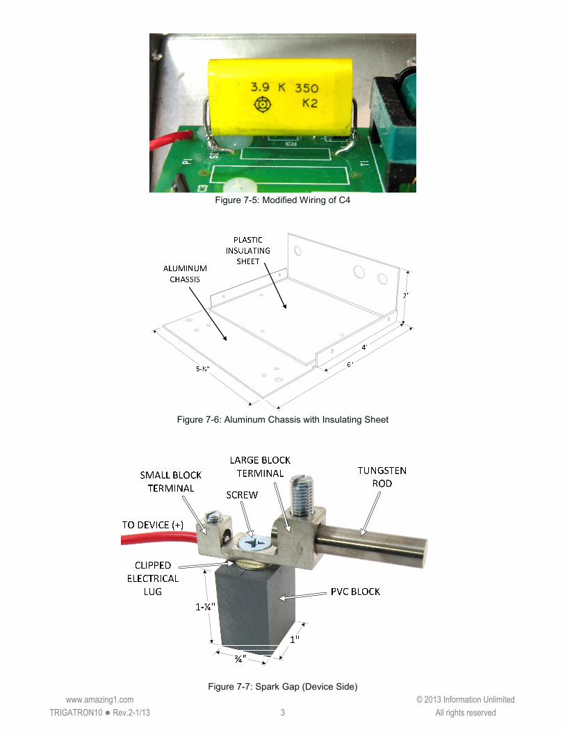
Figure 7-5: Modified Wiring of C4
Figure 7-6: Aluminum Chassis with Insulating Sheet
Figure 7-7: Spark Gap (Device Side)

www.amazing1.com © 2013 Information Unlimited
TRIGATRON10 ● Rev.2-1/13 4 All rights reserved
PVC BLOCK
LARGE BLOCK
TERMINALTUNGSTEN
ROD
TO CAP
BANK (+)
SMALL BLOCK
TERMINAL
CHARGER HV
OUTPUT
SCREW
1"¾"
1-¼"
ELECTRICAL
LUG
Figure 7-8: Spark Gap (Capacitor Bank Side)
Figure 7-9: Short Gap

www.amazing1.com © 2013 Information Unlimited
TRIGATRON10 ● Rev.2-1/13 5 All rights reserved
TO DEVICE (+)
TO 12V SOURCE ON CHARGER
TO DEVICE (-)
TO CAP
BANK (+)
TO CAP
BANK (-)
CHARGER HV OUTPUT
CHARGER (-)
Figure 7-10: Orthogonal View
TO DEVICE (+)
TO 12V SOURCE
ON CHARGER
TO DEVICE (-)
TO CAP
BANK (+)
TO CAP
BANK (-)
CHARGER HV
OUTPUTCHARGER (-)
3 DIODES
(D1X, D2X, D3X)
T2
SHORT
GAP
C1X, C2X 1/16"
GAP
Figure 7-11: Top-Down View

www.amazing1.com © 2013 Information Unlimited
TRIGATRON10 ● Rev.2-1/13 6 All rights reserved
SAFETY
SHIELD
5"
4"
3"
Hole for Cap Bank (+) wire
Figure 7-12: Safety Shield