
CHAPTER 6: Substructure - Premier Guarantee · CHAPTER 6: Substructure. CONTENTS. 6.1. BASEMENTS...
28
CHAPTER 6: Substructure CONTENTS 6.1 BASEMENTS 6.2 WALLS BELOW GROUND 6.3 DAMP PROOFING 6.4 GROUND FLOORS Chapter 6 93
Transcript of CHAPTER 6: Substructure - Premier Guarantee · CHAPTER 6: Substructure. CONTENTS. 6.1. BASEMENTS...

CHAPTER 6: Substructure
CONTENTS
6.1 BASEMENTS
6.2 WALLS BELOW GROUND
6.3 DAMP PROOFING
6.4 GROUND FLOORS
Chapter 6
93

FUNCTIONAL REQUIREMENTS
Techn
ical Man
ual V
12
- TS-0
11
-12
.00
-01
01
17
© P
remier G
uaran
tee 20
17
FU
NC
TIO
NA
L RE
QU
IRE
ME
NT
S
Workmanshipi. All workmanship must be within defined tolerances as defined in
Chapter 1 of this Manual.ii. All work is to be carried out by a technically competent person in a
workmanlike manner.iii. Certification is required for any work completed by an approved
installer.
Materialsi. All materials should be stored correctly in a manner which will not
cause damage or deterioration of the product.ii. All materials, products and building systems shall be appropriate and
suitable for their intended purpose. iii. The structure shall, unless specifically agreed otherwise with the
Warranty provider, have a life of not less than 60 years. Individual components and assemblies, not integral to the structure, may have a lesser durability, but not in any circumstances less than 15 years.
Designi. Design and specifications shall provide a clear indication of the
design intent and demonstrate a satisfactory level of performance.ii. Basements shall be appropriately designed to ensure that they
adequately provide a suitable barrier against contaminants, ground gases and ground water.
iii. Basement design and construction must be supported by structural calculations provided by a suitably qualified expert.
iv. Design details of the basement waterproofing techniques must be provided prior to commencement onsite.
v. Basements must meet the relevant regional building regulations.vi. All basements must be designed and constructed to meet the
requirements of BS 8102: 2009 and achieve a minimum of a Grade 2 standard, except where defined in the guidance to this chapter.
vii. The basement waterproofing design should be completed by a suitably qualified Waterproofing Specialist. The Waterproofing Specialist must take responsibility for the design liability of the waterproofing system and have appropriate professional indemnity cover which covers their business activities. They must also have an understanding of hydrogeology and soil mechanics and hold a relevant professional qualification i.e. Certificated Surveyor in Structural Waterproofing (CSSW) or similar.
Limitations of Functional Requirementsi. The Functional Requirements are limited by the recommendations
applied to the specific areas covered in this chapter.ii. These Functional Requirements do not and will not apply to create
any policy liability for any remedial works carried out by the contractor or otherwise, nor to any materials used in those remedial works.
6.1 BASEMENTS
DefinitionFor the purposes of this Chapter, a basement is defined as a storey or storeys of a building that is constructed partially or entirely below ground.

Techn
ical Man
ual V
12
- TS-0
11
-12
.00
-01
01
17
© P
remier G
uaran
tee 20
17
CHAPTER 6: SubstructuresCH
AP
TE
R 6
: SUB
STR
UC
TU
RE
S
Chapter 6
95
• They must also have an understanding of hydrogeology and soil mechanics and hold a relevant professional qualification i.e. Certificated Surveyor in Structural Waterproofing (CSSW) or similar.
• Designers must have ongoing involvement during the build, maintaining good communication with site management and providing supervision and guidance wherever necessary.
Note: 1. The need for a dedicated Waterproofing
Specialist within the design team is intended to reduce the incidence of issues where systems are designed without following the advice and considerations detailed within BS 8102 and associated design guides.
Such scenarios may occur where Project Designers take on the role of Waterproofing Designer without sufficient reference to the stated guides, commonly relying on standard design details and without considering all appropriate factors. Please refer to BS 8102 for a list of requirements that a designer must meet in order to fulfil the Waterproofing Designer role which includes carrying professional indemnity insurance cover appropriate to the project.
2. Where relying on the use of waterproofing product manufacturer ‘standard details’, they typically disclaim design responsibility, so it is incumbent on the Waterproofing Design Specialist to ensure that such details are correct and appropriate for the site and structure, or offer suitable variation.
6.1.3 General principle of waterproofing designThe approach detailed within BS 8102 involves assessment of a given site to determine the characteristics that influence risk. With the benefit of knowledge gained through this investigation and assessment, suitable designs for dealing with ground water, gases and contaminants can then be devised and constructed.
6.1.4 Design responsibility• Production of a suitable design is one of
the most important aspects of achieving a successful outcome, where the required standard of environment is created within the basement space and maintained in the long term.
• A common assumption in waterproofing is that workmanship is the most ‘critical factor’, and while this is undeniably important, the highest standards of workmanship will not make-up for inadequate design; hence the correct design is the first step in achieving the desired outcome.
• BS 8102 includes a section on the ‘design team’, which states that the advice of a Geotechnical Specialist be sought for assessment of the geology and hydrogeology, and that a Waterproofing Specialist be included as part of the design team from the earliest stages, so that an integrated and practical waterproofing solution is created.
• The Waterproofing Specialist must take responsibility for the design liability of the waterproofing and have appropriate professional indemnity cover which covers their business activities.
6.1.1 IntroductionThis Chapter provides guidance on the requirements associated with the design and construction of basements and other below ground structures. Principally, this concerns the process by which the risk of ground water penetration is appraised and addressed, so that problems associated with penetration do not occur, while consideration is also given to economic construction.
This process and rationale is primarily detailed within BS 8102 (2009) Code of Practice for protection of below ground structures against water from the ground (and other associated design guides). However, further practical guidance on this and compliance with Warranty requirements is included herein.
6.1.2 Limitations of guidanceThis document is not intended as a standalone design guide and does not include full details of what must be considered to comply with BS 8102. Please see the ‘Bibliography’ at the end of BS 8102:2009 for details of other associated design guides.
It must also be noted that structural waterproofing design and geotechnical investigations are specialist fields, and while general guidance is provided, advice must be sought from suitably experienced parties. An appropriate structural design must be undertaken by a Chartered Structural Engineer.

Techn
ical Man
ual V
12
- TS-0
11
-12
.00
-01
01
17
© P
remier G
uaran
tee 20
17
CHAPTER 6: SubstructuresCH
AP
TE
R 6
: SUB
STR
UC
TU
RE
S
water mains and sewers, as well as stating that it should be assumed that there is risk of waterlogging “even where site examination indicated dry conditions”.
In summary:• The site investigation guides the design, but it
should never be assumed that some degree of water pressure will not occur.
• If no site investigation has been undertaken or there is reasonable doubt as to ground water conditions, pressure to the full height of the below ground structure must be assumed at some point in the life of the structure.
• The Warranty Surveyor may request a copy of the site investigation report, design and associated design rationale.
6.1.6 Water-resisting designThe principle of this is to consider and design for the pressures that the structure/waterproofing must resist based upon the site investigation and risk assessment detailed above. However, it also concerns the means by which the degree of water in the ground can be influenced by design.
6.1.6.1 Structural resistanceThe ability of the structure to provide resistance to the penetration of water has a bearing upon all forms of waterproofing. Retaining walls in plain or reinforced masonry provide comparatively little resistance to the penetration of water under pressure because of the crack pattern associated with the degree of joints (mortar beds) present.
• Soils with low permeability represent a risk of waterlogging or encouraging a ‘perched water table’, where water stands temporarily or permanently within the ground against a structure, and arguably this affects more properties with basements versus the true water table level.
Other factors, such as topography and orientation, may have an impact on the propensity for pressure to come to bear and should also receive consideration. Further guidance on the drainage characteristics associated with different types of ground is included within the Basement Information Centre publication Basements: Waterproofing – General Guidance to BS 8102: 2009.
Ground gases and contaminants must also be considered within the risk assessment.
Note:1. While the site investigation forms part of what
guides the waterproofing design, an equally important consideration is the intended use of the space and implicit consequences in the event that water penetration occurs. For example, in properties where the consequences of penetration would be severe, such as in habitable space, suitably low-risk methods must be provided.
2. Whilst in theory it could be assumed that, based upon a site investigation, the risk of water pressure ever occurring is low, BS 8102 advises that consideration is given to the effects of climate change and burst
3. The early involvement of a Waterproofing Designer is an important consideration because the waterproofing design typically has an influence on elements of the structural and/or architectural design. Early involvement allows the waterproofing to be duly considered in association with these other aspects and prevents situations where design fees are increased as a result of necessary redesign, or where waterproofing is compromised by working within the constraints of an ill-considered structure relative to achieving the required standard of environment.
6.1.5 Site and risk assessmentThe degree of water present within the ground and the propensity for waterlogging to occur over the lifetime of a structure is a principal driver in assessing risk and the degree of waterproofing required. Simplistically, if a basement is constructed into a permanently high water table then the degree of protection will required be greater than a similar structure constructed into a generally dry site.
• An assessment of a site must be based on the results of the site investigation and other site-specific factors.
• Seasonal variations in the water table must be accounted for unless long-term monitoring is undertaken.
• Where standing water levels are not noted during a pre-start site investigation, the drainage characteristics of the ground must receive particular attention.
Techn
ical Man
ual V
12
- TS-0
11
-12
.00
-01
01
17
© P
remier G
uaran
tee 20
17
CHAPTER 6: SubstructuresCH
AP
TE
R 6
: SUB
STR
UC
TU
RE
S
Chapter 6
97
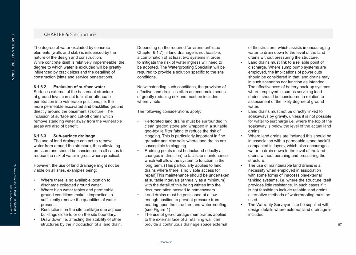
of the structure, which assists in encouraging water to drain down to the level of the land drains without pressuring the structure.
• Land drains must link to a reliable point of discharge. Where sump pump systems are employed, the implications of power cuts should be considered in that land drains may in such scenarios not function as intended. The effectiveness of battery back-up systems, where employed in sumps servicing land drains, should be considered in relation to assessment of the likely degree of ground water.
• Land drains must not be directly linked to soakaways by gravity, unless it is not possible for water to surcharge i.e. where the top of the soakaway is below the level of the actual land drains.
• Where land drains are included this should be in association with a permeable stone backfill compacted in layers, which also encourages water to drain down to the level of the land drains without perching and pressuring the structure.
• The use of maintainable land drains is a necessity when employed in association with some forms of inaccessible/external tanking systems, i.e. where the structure itself provides little resistance. In such cases if it is not feasible to include reliable land drains, alternative methods of waterproofing must be used.
• The Warranty Surveyor is to be supplied with design details where external land drainage is included.
Depending on the required ‘environment’ (see Chapter 6.1.7), if land drainage is not feasible, a combination of at least two systems in order to mitigate the risk of water ingress will need to be adopted. The Waterproofing Specialist will be required to provide a solution specific to the site conditions.
Notwithstanding such conditions, the provision of effective land drains is often an economic means of greatly reducing risk and must be included where viable.
The following considerations apply:
• Perforated land drains must be surrounded in clean graded stone and wrapped in a suitable geo-textile filter fabric to reduce the risk of clogging. This is particularly important in fine granular and clay soils where land drains are susceptible to clogging.
• Rodding points must be included (ideally at changes in direction) to facilitate maintenance, which will allow the system to function in the long term. (This particularly applies to land drains where there is no viable access for repair)This maintenance should be undertaken at suitable intervals (annually as a minimum), with the detail of this being written into the documentation passed to homeowners.
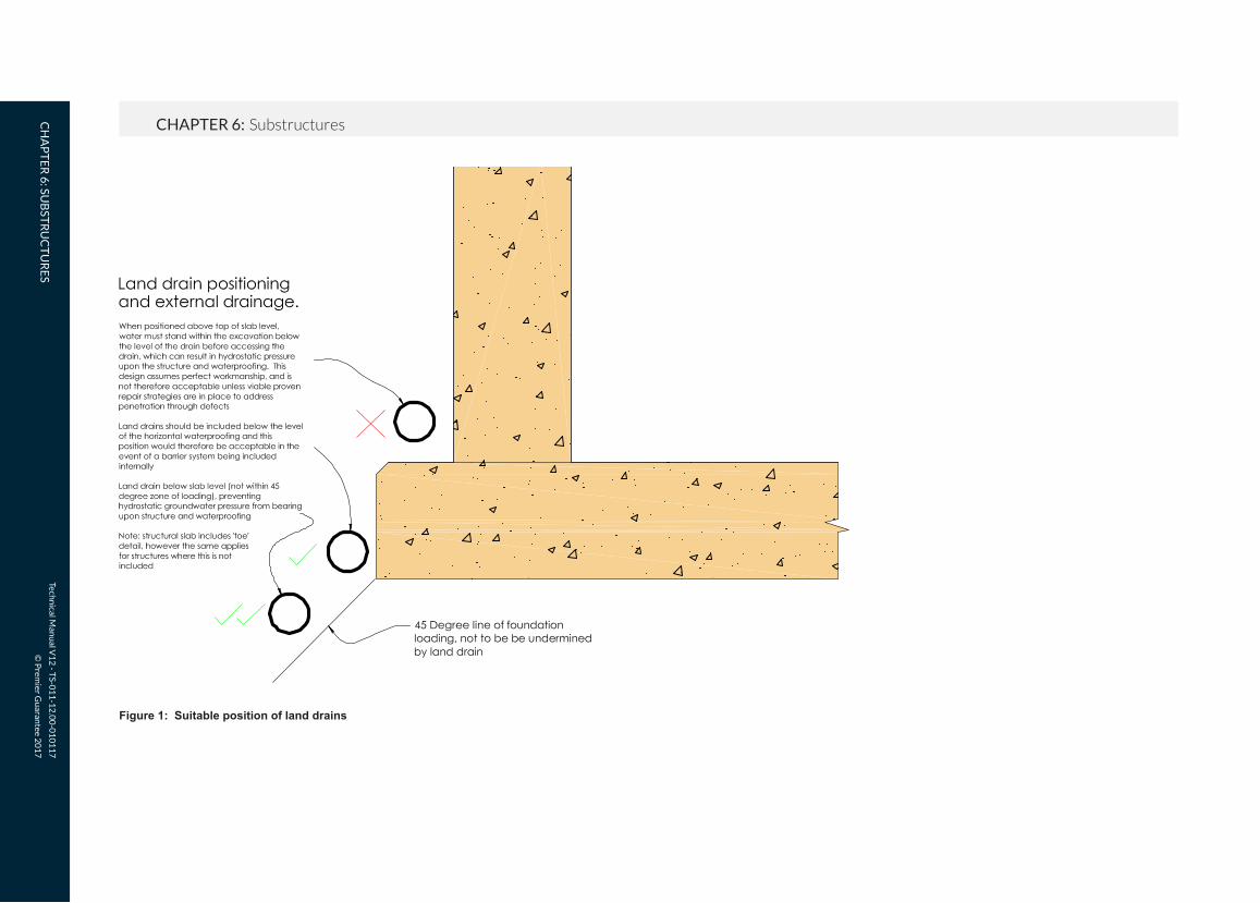
• Land drains must be positioned at a low enough position to prevent pressure from bearing upon the structure and waterproofing. (see Figure 1)
• The use of geo-drainage membranes applied to the external face of a retaining wall can provide a continuous drainage space external
The degree of water excluded by concrete elements (walls and slab) is influenced by the nature of the design and construction. While concrete itself is relatively impermeable, the degree to which water is excluded will be greatly influenced by crack sizes and the detailing of construction joints and service penetrations.
6.1.6.2 Exclusion of surface waterSurfaces external of the basement structure at ground level can act to limit or attenuate penetration into vulnerable positions, i.e. the more permeable excavated and backfilled ground directly around the basement structure. The inclusion of surface and cut-off drains which remove standing water away from the vulnerable areas are also of benefit.
6.1.6.3 Sub-surface drainageThe use of land drainage can act to remove water from around the structure, thus alleviating pressure and should be considered in all cases to reduce the risk of water ingress where practical.
However, the use of land drainage might not be viable on all sites, examples being:
• Where there is no available location to discharge collected ground water.
• Where high water tables and permeable ground conditions make it impractical to sufficiently remove the quantities of water present.
• Restrictions on the site curtilage due adjacent buildings close to or on the site boundary.
• Draw down i.e. affecting the stability of other structures by the introduction of a land drain.
Techn
ical Man
ual V
12
- TS-0
11
-12
.00
-01
01
17
© P
remier G
uaran
tee 20
17
CHAPTER 6: SubstructuresCH
AP
TE
R 6
: SUB
STR
UC
TU
RE
S
Figure 1: Suitable position of land drains

Techn
ical Man
ual V
12
- TS-0
11
-12
.00
-01
01
17
© P
remier G
uaran
tee 20
17
CHAPTER 6: SubstructuresCH
AP
TE
R 6
: SUB
STR
UC
TU
RE
S
Chapter 6
99
home), lifts / escalators, access stairs and lobbies that are associated within an underground car park, a Grade 2 standard is the minimum grade to be expected.
The degree of seepage or dampness (water tightness) that can be tolerated for this particular end use needs to be established and agreed with all interested parties, including the Warranty Surveyor at the design stage. To assist with quantifying an acceptable level of moisture ingress, the following definitions of water tightness are provided. These are taken from the publication ‘Specification for piling and embedded retaining walls’.
• Damp patch: When touched, a damp patch may leave a slight film of moisture on the hand, but no droplets of water or greater degrees of wetness are left on the hand. On a concrete surface a damp patch is discernible from a darkening of the colour of the concrete.
• Beading of water: Beading of water is the state in which individual droplets of water (held by surface tension effects) form on the surface of the wall and adhere to the wall. The water beads do not coalesce and do not flow.
• Weeping of water (seepage): Weeping of water is the state in which droplets of water form on the surface of the wall and coalesce with other droplets. The coalesced water does not remain stationary on the wall surface, but instead flows down the wall.
Grades of waterproofing protection
• For Warranty purposes we require all basements to be designed and constructed to a minimum of Grade 2, with Grade 3 being necessary for occupied space. An exception to this is a basement used solely for underground car parking, where a Grade 1 could be accepted; see note 6.1.7.1 below for specific guidance.
• Habitable space is Grade 3 where water penetration is unacceptable. Appropriately designed environmental controls, such as vapour barriers, insulation, heating, ventilation and dehumidification must be included to control vapour introduced via occupation sufficiently thereby preventing problems of condensation.
• An example usage for Grade 2 includes store rooms, and again water penetration is not acceptable however, heating and ventilation is not necessarily required, albeit that some degree of ventilation is recommended even in basic storage space, which may otherwise suffer condensation-related dampness.
6.1.7.1 Underground car parkingIn the case of underground car parking with associated underground refuse stores and cycle stores; some seepage, dampness or condensation as well as standing water (from vehicles) is to be expected.
For this type of use, a design by water proofing design specialist to a BS 8102 Grade 1 standard could be accepted. For plant rooms (that do not house items of plant that directly service the
Grade Example of use of structure
Performance level
1 Car Parking; plantrooms (excluding electrical equipment); workshops.
Some seepage and damp areas tolerable, dependent on intended use.
2 Plant rooms and workshops requiring a drier environment (than Grade 1); storage areas
No water penetration acceptable.Damp areas tolerable; ventilation might be required.
3 Ventilated residential and commercial areas, including offices, restaurants etc; leisure centres
No water penetration acceptable.Ventilation, dehumidification or air conditioning necessary, appropriate to the intended use.
6.1.7 Intended use and required standard of environmentUsage dictates the required ‘grade’ of environment, i.e. how ‘dry’ a given basement space must be in order to be suitable for a given usage.
The designer must therefore consider how this will be achieved in a particular site and structure. BS 8102: 2009 Table 2 provides three definitions of environmental grades (Grades 1, 2 and 3) as follows:

Techn
ical Man
ual V
12
- TS-0
11
-12
.00
-01
01
17
© P
remier G
uaran
tee 20
17
CHAPTER 6: SubstructuresCH
AP
TE
R 6
: SUB
STR
UC
TU
RE
S
Section 2.2.3 of CIRIA Report 139 provides guidance on quantifying the required internal environment and places limits on Grade 1 basements:
It identifies:
• The functioning of mechanical plant and electrical switchgear is not normally unaffected by seepage through walls and floors, provided the water does not impinge directly onto the equipment. However, a wet floor can be hazard to maintenance staff as well as increase the rate of corrosion of steel casings and frames in contact with it. Generally, a raised working area may be desirable, and all equipment should be mounted on plinths.
• Atmospheric moisture is unlikely to affect mechanical plant unless it is continually at such a level as to cause an unreasonable fast rate of corrosion. One exception is that air compressors need to be fitted with air-driers if they are to operate in constantly damp conditions. Ferrous pipes, conduits, wall brackets and their fixings etc. will corrode if unprotected.
• Damp air may cause electrical installations to malfunction. Permanently damp conditions may encourage biological degradation of plastic insulation. Ventilation of the plant space is therefore important.
• Water ingress to underground car parks must similarly be controlled. Cars are likely to introduce significant amounts of water on wet days, which should be drained away. There is also the danger of corrosion and discoloration of paintwork on the cars due to seepage through the ceiling slab (podium deck).
Summary of environmental parameters:
• Relative humidity: Items stored in such basements should not normally be unduly affected by high relative humidity. Ventilation provision draws air directly from the atmosphere and conditions equivalent to prevailing atmosphere, RH greater than 65% (normally UK external range), are therefore acceptable.
• Temperature: Grade 1 basement would not normally be heated.
• Dampness: The requirements for dampness will depend on whether the basement is to be decorated in any way and the sensitivity of any electrical equipment to be installed (i.e. light fittings, switches, cable runs/conduits etc.). If the basement is not to be decorated then visible damp patches may be tolerated. A higher waterproofing specification may be required if the walls are to be painted, etc. It is normally expected that the construction materials will not be wetter than 85% RH.
• Wetness: Minor seepage would be acceptable through the walls and joints if the basement is not to be decorated.
• The need for drainage within the basement, i.e. channels along perimeter walls and across car parking areas, should also be determined, together with requirements for ventilation.
• Where necessary, consideration should also be given to whether additional protection measures are required to plant and equipment, electrical switchgear, support brackets etc.,
Once the most appropriate level of water tightness has been determined, the Waterproofing Specialist should factor this into his design and specify a suitable waterproofing system that will achieve the required level of performance. Full design details and justification of the proposed method of waterproofing must be submitted and approved by the Warranty Surveyor prior to work commencing on site.
6.1.8 Defects and remedial measuresWithin BS 8102 designers are advised to consider the probability that systems may not be installed perfectly, and that defects may occur as a result of this or defects may be present in the supplied materials.
Designing on the assumption that a system will not be totally perfect or free of defects necessitates that consideration is given to the feasibility of repairing those defects, or ensuring that they are of no consequence i.e. where systems are not accessible for repair. Different structures, waterproofing systems and sites have a bearing upon this consideration. For Warranty purposes a Grade 3 environment basement must be designed so that the consideration of reparability is essential.
Strategies for repair of a Grade 1 or 2 environment basement must be considered as part of the design process, further commentary is provided within each of the specific system type sections.
The detail of an appropriate repair strategy may be requested by the Warranty Surveyor in relation to a given waterproofing design.

Techn
ical Man
ual V
12
- TS-0
11
-12
.00
-01
01
17
© P
remier G
uaran
tee 20
17
CHAPTER 6: SubstructuresCH
AP
TE
R 6
: SUB
STR
UC
TU
RE
S
Chapter 6
101
6.1.9 Forms of waterproofingBS 8102 defines three forms of waterproofing protection: Type A, barrier protection (commonly referred to as ‘tanking’), Type B, structurally integral protection, and Type C, drained protection.
6.1.9.1 Type A, barrier protectionThis form of waterproofing relies on the inclusion of a physical barrier material applied on or within the structure, often where the structure itself provides little resistance to the penetration of water. A variety of considerations apply:
• Suitability of the substrate, primarily applicable where tanking products are applied internally, in that the bond between the product and the substrate on which it is applied must be sufficient to resist hydrostatic ground water pressure.
• The requirement for preparation of substrates to accept tanking mediums.
• Movement, which in rigid tanking systems may encourage cracking through which water may penetrate, where pressure comes to bear.
• Loading, where hydrostatic pressure is applied to the structure as a result of exclusion via the tanking medium, i.e. structures must be designed to resist loads applied to them.
• Continuity, in that systems must in virtually all cases be ‘continuous’, as a gap in a barrier system represents a point at which water under pressure can penetrate.
• ‘Buildability’, namely whereby sheet membrane products are proposed, with the consideration being the practicality of wrapping a flat sheet around complex three dimensional shapes such as external corners and beneath raft slab thickened toe details.
Figure 2: Type A, barrier protection
Commentary on 6.1.9.1:
• Whilst BS 8102 advises that ‘reparability’ must be considered, the use of external adhesive membrane tanking systems on permeable constructions is precluded, unless employed in association with long-term strategies for preventing ground water from pressuring, e.g. serviceable land drains.
• External systems have a greater implication, in that accessibility for repair is typically impractical post-construction and where combined with relatively permeable wall constructions, makes it difficult to
confidently determine the point of a defect externally, because water can track within the wall construction to show itself internally at a position not local to the external defect.
• Internal systems have the benefit of greater accessibility meaning that repair is more feasible. Where this system is chosen, the strength of the substrate, its surface preparation and the bond of the water proofing system are critical considerations and need to be properly considered by the water proofing specialist.
Techn
ical Man
ual V
12
- TS-0
11
-12
.00
-01
01
17
© P
remier G
uaran
tee 20
17
CHAPTER 6: SubstructuresCH
AP
TE
R 6
: SUB
STR
UC
TU
RE
S
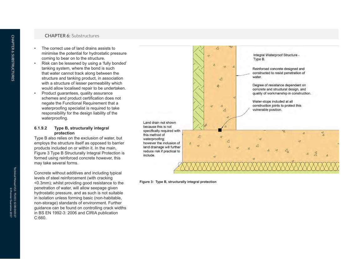
• The correct use of land drains assists to minimise the potential for hydrostatic pressure coming to bear on to the structure.
• Risk can be lessened by using a ‘fully bonded’ tanking system, where the bond is such that water cannot track along between the structure and tanking product, in association with a structure of lesser permeability which would allow localised repair to be undertaken.
• Product guarantees, quality assurance schemes and product certification does not negate the Functional Requirement that a waterproofing specialist is required to take responsibility for the design liability of the waterproofing.
6.1.9.2 Type B, structurally integral protectionType B also relies on the exclusion of water, but employs the structure itself as opposed to barrier products included on or within it. In the main, Figure 3 Type B Structurally Integral Protection is formed using reinforced concrete however, this may take several forms.
Concrete without additives and including typical levels of steel reinforcement (with cracking <0.3mm); whilst providing good resistance to the penetration of water, will allow seepage given hydrostatic pressure, and as such is not suitable in isolation unless forming basic (non-habitable, non-storage) standards of environment. Further guidance can be found on controlling crack widths in BS EN 1992-3: 2006 and CIRIA publication C:660.
Figure 3: Type B, structurally integral protection

Techn
ical Man
ual V
12
- TS-0
11
-12
.00
-01
01
17
© P
remier G
uaran
tee 20
17
CHAPTER 6: SubstructuresCH
AP
TE
R 6
: SUB
STR
UC
TU
RE
S
Chapter 6
103
6.1.9.3.2 Internal drainageThe internal drainage system comprises of three elements:
• A drainage channel detail recessed into the floor construction.
• A means of water discharge, which in a basement fully below ground requires a sump pump system or in a sloping site may be via gravity.
• Vapour barrier drainage membranes included above or internal of the drainage system which isolate the internal environment from the damp substrates behind.
Whilst the drainage channel is intended only to deal with minor seepage water and could alternatively be linked into deeper fixed drains to drain out via gravity, the risks associated with the surcharge of external drains are high and this practice is excluded from Warranty cover.
Drained protection systems are reliant on their ability to remove seepage water and so the mechanism by which water is removed requires careful consideration. The extent of seepage water penetration also has a bearing on the capacity required, with the degree of penetration being influenced by the permeability of the structure and the ground water conditions externally.
Notwithstanding the above, the capacity of such systems to remove water must be adequate to deal with a worst-case scenario and should be engineered with this in mind to provide a suitably low-risk system.
Commentary to 6.1.9.2:
• With regard to appraisal of repair, this method has a benefit in that; the point of penetration is typically the point of the defect or pathway through which water penetration occurs. Coupled with the impermeable nature of the structure generally, this allows localised repair to be undertaken via resin injection, grouting and associated repair methods
• The main consideration is locating the point of any penetration, and it is therefore beneficial where reasonable access to the concrete structure remains viable
• Product guarantees, quality assurance schemes and product certification does not negate the Functional Requirement that a waterproofing specialist is required to take responsibility for the design liability of the waterproofing
6.1.9.3 Type C, drained protectionThis method of waterproofing differs from Type A and Type B as the structure is employed to limit penetration while an internal drainage system collects and removes any seepage water.
6.1.9.3.1 The Structure
• The ‘structure’ provides the primary resistance to ground water pressure. A Type C drainage system is designed to mitigate the risk by removing any minor water seepage through the structure and in doing so maintains the required internal environment.
• An assessment of the structure is required to ensure it provides the primary level of water resistance by the Waterproofing Specialist
As with any structure that aims to entirely block out water, this must be free of defects which would otherwise allow water to penetrate. In achieving this, the following must be considered:
• Structural design and specification of materials (based in part on-site assessment).
• Water stop detailing at construction joints• Service penetration detailing.• Appropriate specialist site supervision to
ensure high standards of workmanship.• Good placement and compaction.• Curing.
Particular consideration must be given to the formation of construction joint details, which form a typical weak point in Type B structures. Furthermore, specialist supervision is required on site during construction.
Systems which function by excluding water may not be tested until the ground water pressure comes to bear. Therefore, it is advantageous where external water pressure comes to bear prior to completion that any areas of penetration can be remedied during construction.

Techn
ical Man
ual V
12
- TS-0
11
-12
.00
-01
01
17
© P
remier G
uaran
tee 20
17
CHAPTER 6: SubstructuresCH
AP
TE
R 6
: SUB
STR
UC
TU
RE
S
Figure 4: Type C, drained protection
• Sump pump systems must include mechanical redundancy (dual mains powered pumps) to protect against pump failure and also sufficient battery back-up protection to protect in the event of a power cut.
• Each pump within a given system should have independent direct spur RCD/power supply so that in the event of an issue with a pump the others will still have power. Direct spur is advised to prevent accidental turning off by homeowners.
• Drainage systems typically discharge into surface water gullies at external ground floor level, and an overflow detail must be formed at the point of discharge to allow water to spill out externally in the event of drains blocking or surcharging.
• Systems can drain by gravity to low ground externally i.e. where properties are part retaining and constructed into sloping sites. As with pumped systems, if connecting to mains drains an overflow detail must be employed to allow water to spill externally in the event of an issue.
• Internal drained protection systems must include drainage channels local to the external wall floor junctions which facilitates maintenance and allows systems to function and protect in the long term. Where larger footprints are involved cross floor channels must be included, ideally local to construction joints where the structure is more vulnerable to ground water penetration.
Techn
ical Man
ual V
12
- TS-0
11
-12
.00
-01
01
17
© P
remier G
uaran
tee 20
17
CHAPTER 6: SubstructuresCH
AP
TE
R 6
: SUB
STR
UC
TU
RE
S
Chapter 6
105
6.1.9.3.3 MaintenanceSystems must be maintained annually as a minimum. The detail of this requirement must be included in the documentation provided to the homeowner who will then be responsible for ongoing operation and maintenance of the system, the ongoing maintenance should include: • The service records of the maintenance of the
system.• Accessibility to drainage channels and sumps
are available at all times.• That the drainage channels and sumps are
checked at the service intervals to ensure they are clear and free of any free lime build up.
• Ensure that the electrical supply, battery back up and alarm systems are fully operational at all times.
6.1.9.3.4 Free lime Water moving over and through new concrete walls and floors leaches free lime within the early life of the structure, and suitable treatments should be applied to concrete to minimise this.
• The Waterproofing Specialist should provide a specification of the treatments to be used appropriate for the particular construction and made available to the Warranty Surveyor if requested.
• Where basements are formed under existing buildings in conjunction with new under pinning works; the choice of dry packing should be carefully specified and a waterproof expanding type mortar is recommended to help avoid free lime occurrences.
• Substrates should be clean and free of loose or friable materials prior to the application of membrane linings.
6.1.9.3.5 General
• Flood testing of a system should be undertaken during construction to check efficiency and that water flows freely to the discharge point. Testing in this manner to prove that the system functions as intended, is a key benefit of this method of waterproofing and must be part of the process.
• Systems creating a habitable space require the inclusion of vapour barrier drainage membranes within the wall and floor construction.
• Where elements of the drained protection system are included within cavities, the cavities must be kept clear of mortar snots and debris.
• Continuity of the structure must be considered because the resistance to water provided by a given structure is reduced by apertures through which water can freely move. Examples could include holes present within existing buildings, or in new construction where land drains are linked to sump pump systems, with the sumps being installed internal of the retaining shell, e.g. in light wells, thus providing a pathway for water to enter.
• Temporary 110v pumps should be included during construction to address water penetration as necessary; 240v systems should be installed and commissioned as soon as viable once the 240v supply is installed.
• Systems must not link directly by gravity
to soakaways where any of the previously stated scenarios occur because of the danger of backflow of water through the pipes or waterlogging of the local ground above slab/DPM level. However, where such conditions are not present, sump pump systems may be employed to lift water up to ground level externally, discharging into gullies linked to soakaways. This detail should be designed by the Waterproofing Specialist.
Commentary to 6.1.9.3:
• In consideration of the repair of defects, the inclusion of drained protection systems internally generally ensures that systems can be accessed for localised repair; however, this may be lessened where systems are sandwiched within the structure, i.e. within cavities.
• Product guarantees, quality assurance schemes and product certification does not negate the Functional Requirement that a waterproofing specialist is required to take responsibility for the design liability of the waterproofing
• Part of the underlying rationale of drained protection is that water is removed continuously, so that it does not collect and removes pressure upon membrane linings installed over the drainage. If water does not place pressure upon such membranes, then the incidence of any defects within them is generally of no consequence, and so maintaining the efficiency of the drainage in the long term ensures that such defects are negated.
Techn
ical Man
ual V
12
- TS-0
11
-12
.00
-01
01
17
© P
remier G
uaran
tee 20
17
CHAPTER 6: SubstructuresCH
AP
TE
R 6
: SUB
STR
UC
TU
RE
S
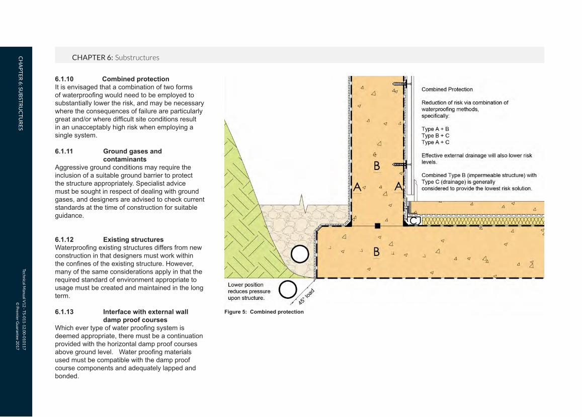
6.1.10 Combined protectionIt is envisaged that a combination of two forms of waterproofing would need to be employed to substantially lower the risk, and may be necessary where the consequences of failure are particularly great and/or where difficult site conditions result in an unacceptably high risk when employing a single system.
6.1.11 Ground gases and contaminantsAggressive ground conditions may require the inclusion of a suitable ground barrier to protect the structure appropriately. Specialist advice must be sought in respect of dealing with ground gases, and designers are advised to check current standards at the time of construction for suitable guidance.
6.1.12 Existing structuresWaterproofing existing structures differs from new construction in that designers must work within the confines of the existing structure. However, many of the same considerations apply in that the required standard of environment appropriate to usage must be created and maintained in the long term.
6.1.13 Interface with external wall damp proof coursesWhich ever type of water proofing system is deemed appropriate, there must be a continuation provided with the horizontal damp proof courses above ground level. Water proofing materials used must be compatible with the damp proof course components and adequately lapped and bonded.
Figure 5: Combined protection

Techn
ical Man
ual V
12
- TS-0
11
-12
.00
-01
01
17
© P
remier G
uaran
tee 20
17
CHAPTER 6: SubstructuresCH
AP
TE
R 6
: SUB
STR
UC
TU
RE
S
Chapter 6
107
Figure 5.1 below shows a typical situation with a Type A barrier protection. The waterproofing specialist must advise the Designer of the correct detailing for the project allowing for any sloping site conditions which may necessitate a stepped DPC provision.
DPC
DPC Cavity Tray Externally appliedwaterproofing systemtaken above basementwall and lapped behindcavity tray at least 150mmabove ground level
Full height open perpends toprovide drainage to cavity
Basement wallconstruction
Geo drainage membrane
GL
Figure 5.1: Typical Interface of basement water proofing system with above ground horizontal DPC
FUNCTIONAL REQUIREMENTS
Techn
ical Man
ual V
12
- TS-0
11
-12
.00
-01
01
17
© P
remier G
uaran
tee 20
17
FU
NC
TIO
NA
L RE
QU
IRE
ME
NT
S
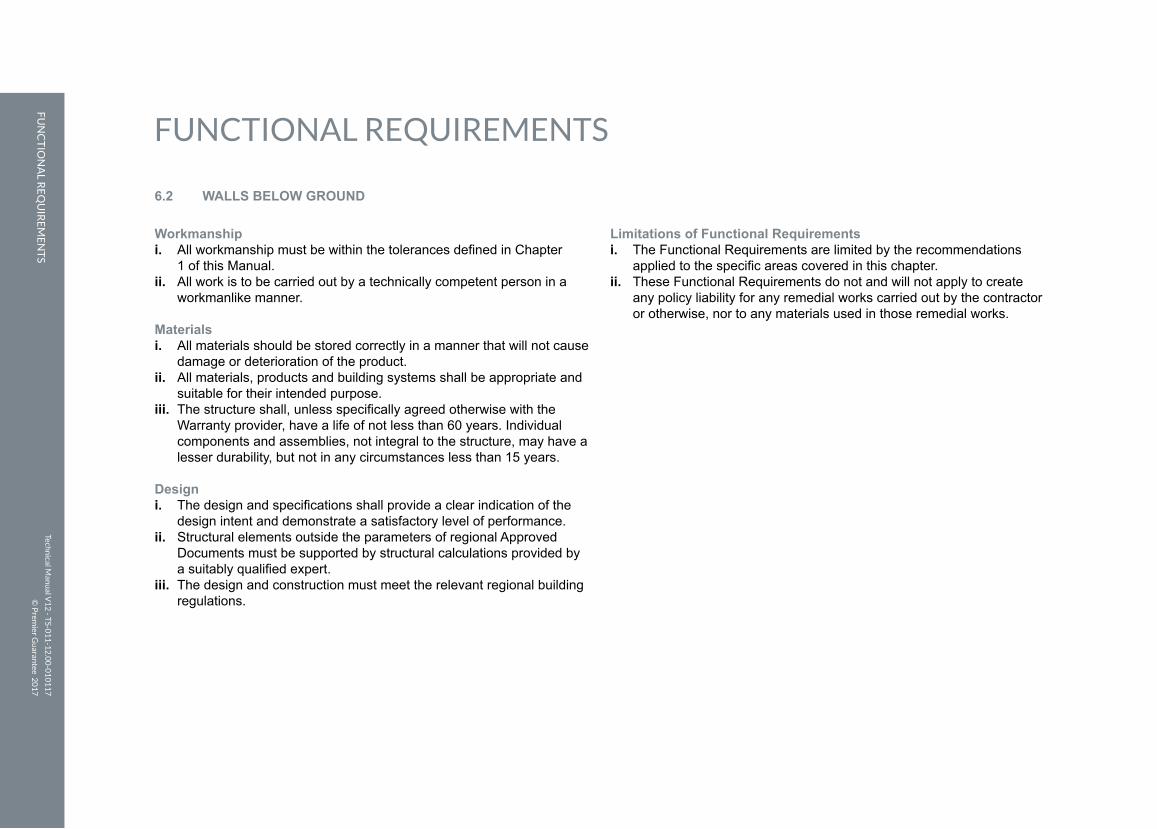
Workmanshipi. All workmanship must be within the tolerances defined in Chapter 1 of this Manual.ii. All work is to be carried out by a technically competent person in a
workmanlike manner.
Materialsi. All materials should be stored correctly in a manner that will not cause
damage or deterioration of the product.ii. All materials, products and building systems shall be appropriate and
suitable for their intended purpose. iii. The structure shall, unless specifically agreed otherwise with the
Warranty provider, have a life of not less than 60 years. Individual components and assemblies, not integral to the structure, may have a lesser durability, but not in any circumstances less than 15 years.
Designi. The design and specifications shall provide a clear indication of the
design intent and demonstrate a satisfactory level of performance.ii. Structural elements outside the parameters of regional Approved
Documents must be supported by structural calculations provided by a suitably qualified expert.
iii. The design and construction must meet the relevant regional building regulations.
Limitations of Functional Requirementsi. The Functional Requirements are limited by the recommendations
applied to the specific areas covered in this chapter.ii. These Functional Requirements do not and will not apply to create
any policy liability for any remedial works carried out by the contractor or otherwise, nor to any materials used in those remedial works.
6.2 WALLS BELOW GROUND
Techn
ical Man
ual V
12
- TS-0
11
-12
.00
-01
01
17
© P
remier G
uaran
tee 20
17
CHAPTER 6: SubstructuresCH
AP
TE
R 6
: SUB
STR
UC
TU
RE
S
Chapter 6
109
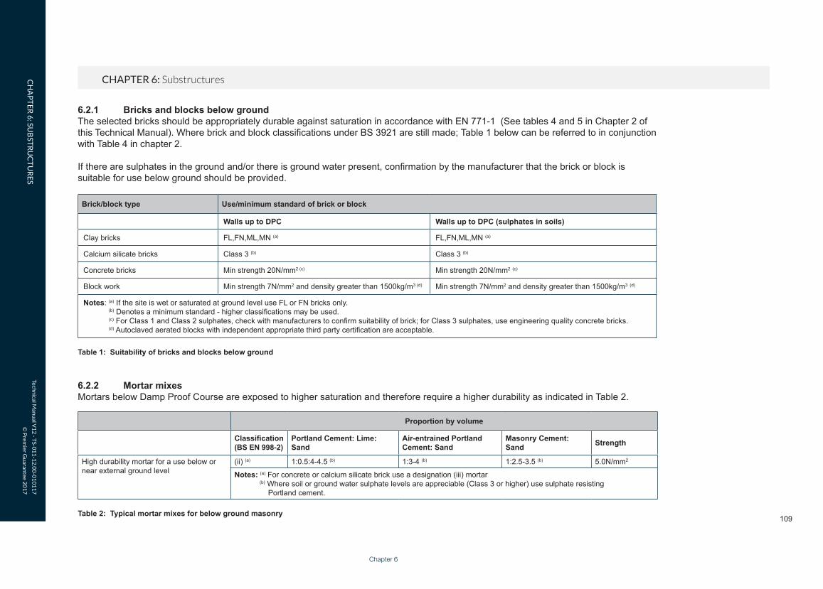
6.2.1 Bricks and blocks below groundThe selected bricks should be appropriately durable against saturation in accordance with EN 771-1 (See tables 4 and 5 in Chapter 2 of this Technical Manual). Where brick and block classifications under BS 3921 are still made; Table 1 below can be referred to in conjunction with Table 4 in chapter 2.
If there are sulphates in the ground and/or there is ground water present, confirmation by the manufacturer that the brick or block is suitable for use below ground should be provided.
Brick/block type Use/minimum standard of brick or block
Walls up to DPC Walls up to DPC (sulphates in soils)
Clay bricks FL,FN,ML,MN (a) FL,FN,ML,MN (a)
Calcium silicate bricks Class 3 (b) Class 3 (b)
Concrete bricks Min strength 20N/mm2 (c) Min strength 20N/mm2 (c)
Block work Min strength 7N/mm2 and density greater than 1500kg/m3 (d) Min strength 7N/mm2 and density greater than 1500kg/m3 (d)
Notes: (a) If the site is wet or saturated at ground level use FL or FN bricks only. (b) Denotes a minimum standard - higher classifications may be used. (c) For Class 1 and Class 2 sulphates, check with manufacturers to confirm suitability of brick; for Class 3 sulphates, use engineering quality concrete bricks. (d) Autoclaved aerated blocks with independent appropriate third party certification are acceptable.
Table 1: Suitability of bricks and blocks below ground
6.2.2 Mortar mixesMortars below Damp Proof Course are exposed to higher saturation and therefore require a higher durability as indicated in Table 2.
Proportion by volume
Classification(BS EN 998-2)
Portland Cement: Lime: Sand
Air-entrained Portland Cement: Sand
Masonry Cement: Sand Strength
High durability mortar for a use below or near external ground level
(ii) (a) 1:0.5:4-4.5 (b) 1:3-4 (b) 1:2.5-3.5 (b) 5.0N/mm2
Notes: (a) For concrete or calcium silicate brick use a designation (iii) mortar (b) Where soil or ground water sulphate levels are appreciable (Class 3 or higher) use sulphate resisting Portland cement.
Table 2: Typical mortar mixes for below ground masonry

Techn
ical Man
ual V
12
- TS-0
11
-12
.00
-01
01
17
© P
remier G
uaran
tee 20
17
CHAPTER 6: SubstructuresCH
AP
TE
R 6
: SUB
STR
UC
TU
RE
S
6.2.3 Cavities below groundCavities below ground should be filled with concrete, ensuring there is a minimum gap, as indicated in Figure 6 and Figure 7, between the DPC and the top of the concrete. The concrete should be of a GEN1 grade and a consistence class of S3.
Figure 6: Concrete cavity fill: traditional ground bearing slab Figure 7: Concrete cavity fill: beam and block floor

FUNCTIONAL REQUIREMENTS
Techn
ical Man
ual V
12
- TS-0
11
-12
.00
-01
01
17
© P
remier G
uaran
tee 20
17
FU
NC
TIO
NA
L RE
QU
IRE
ME
NT
S
111
Workmanshipi. All workmanship must be within the tolerances defined in Chapter 1 of this Manual.ii. All work is to be carried out by a technically competent person in a
workmanlike manner.iii. Certification is required for any work completed by an approved
installer.
Materialsi. All materials should be stored correctly in a manner that will not cause
damage or deterioration of the product.ii. All materials, products and building systems shall be appropriate and
suitable for their intended purpose. iii. The structure shall, unless specifically agreed otherwise with the
Warranty provider, have a life of not less than 60 years. Individual components and assemblies, not integral to the structure, may have a lesser durability, but not in any circumstances less than 15 years.
Designi. The design and specifications shall provide a clear indication of the
design intent and demonstrate a satisfactory level of performance.ii. Damp proofing works should prevent any external moisture passing
into the internal environment of the dwelling.iii. Structural elements outside the parameters of regional Approved
Documents must be supported by structural calculations provided by a suitably qualified expert.
iv. The design and construction must meet the relevant regional building regulations.
Limitations of Functional Requirementsi. The Functional Requirements are limited by the recommendations
applied to the specific areas covered in this chapter.ii. These Functional Requirements do not and will not apply to create
any policy liability for any remedial works carried out by the contractor or otherwise, nor to any materials used in those remedial works.
6.3 DAMP PROOFING
Chapter 6

Techn
ical Man
ual V
12
- TS-0
11
-12
.00
-01
01
17
© P
remier G
uaran
tee 20
17
CHAPTER 6: SubstructuresCH
AP
TE
R 6
: SUB
STR
UC
TU
RE
S
DPM
DPC
DPC
Ground floor slab tobe suspended if fillmaterial exceeds600mm
A Waterproof specialist must select anapproved waterproof membrane to meetthe requirements of BS 8102 to provide acontinuous barrier that is compatible withthe floor DPM /DPC
Extra wide DPC lappedonto vertical andhorizontal DPM's
6.3.3 Stepped membranesDPM should be continuous where floors are stepped, as illustrated in Figure 8.
6.3.1 Damp proof courses (DPC)Damp Proof Courses should be of a flexible material that is suitable for its intended use, and the DPC should have appropriate third-part certification. Generally, blue brick or slates will not be accepted as a DPC.
DPC should be laid on a mortar bed and correctly lapped at junctions and corners. The depth of lap should be the same as the width of the DPC.
DPC should not bridge any cavities unless it is acting as a cavity tray. Where a cavity tray is required (e.g. over a telescopic floor vent) please refer to chapter 7, section 7.1, for further guidance on cavity tray, weep holes and stop end requirements.
6.3.2 Damp proof membranes (DPM)DPM should be provided beneath all ground-supported slabs or cast in-situ reinforced slabs. Membranes should be linked to the DPC and be a minimum 1200g polythene. Membranes should be laid either onto a concrete slab or onto a minimum 5mm sand blinding (if laid below a floor slab).
Other DPM may be considered if they have appropriate third-party certification and are installed in accordance with the manufacturer’s instructions.
Figure 8: Stepped Damp Proof Membrane

FUNCTIONAL REQUIREMENTS
Techn
ical Man
ual V
12
- TS-0
11
-12
.00
-01
01
17
© P
remier G
uaran
tee 20
17
FU
NC
TIO
NA
L RE
QU
IRE
ME
NT
S
113
Workmanshipi. All workmanship must be within the tolerances defined in Chapter 1 of this Manual.ii. All work is to be carried out by a technically competent person in a
workmanlike manner.
Materialsi. All materials should be stored correctly in a manner that will not cause
damage or deterioration of the product.ii. All materials, products and building systems shall be appropriate and
suitable for their intended purpose. iii. The structure shall, unless specifically agreed otherwise with the
Warranty provider, have a life of not less than 60 years. Individual components and assemblies, not integral to the structure, may have a lesser durability, but not in any circumstances less than 15 years.
Designi. The design and specifications shall provide a clear indication of the
design intent and demonstrate a satisfactory level of performance.ii. Structural elements outside the parameters of regional Approved
Documents must be supported by structural calculations provided by a suitably qualified expert.
iii. The design and construction must meet the relevant regional building regulations.
iv. Precast structural elements must have structural calculations that prove their adequacy endorsed by the manufacturer.
Limitations of Functional Requirementsi. The Functional Requirements are limited by the recommendations
applied to the specific areas covered in this chapter.ii. These Functional Requirements do not and will not apply to create any
policy liability for any remedial works carried out by the contractor or otherwise, nor to any materials used in those remedial works.
6.4 GROUND FLOORS
Chapter 6

Techn
ical Man
ual V
12
- TS-0
11
-12
.00
-01
01
17
© P
remier G
uaran
tee 20
17
CHAPTER 6: SubstructuresCH
AP
TE
R 6
: SUB
STR
UC
TU
RE
S
6.4.1.2 Damp proof membranes (DPM)DPM can be laid either above or below the floor slab depending on the finish of the floor. The membrane should be lapped into the DPC by at least 100mm.
Figure 9: Typical ground bearing floor slab
6.4.1.3 InsulationInsulation that is to be provided to ground floor can be placed either above or below the concrete slab. Insulation should be installed in accordance with the manufacturer’s instructions and be durable enough to withstand floor loadings and moisture. A number of insulation products require an additional DPM to protect the surface of the insulation. It is important that this additional membrane is incorporated, which is shown in Figure 9.
6.4.1.4 Concreting of floorsPrior to concreting, any water or debris that may have collected on top of the DPM should be removed. Concrete should ideally be ready mixed and be of at least GEN3. Expansion joints should be provided in accordance with Chapter 2.2 of this Manual.
6.4.2 Suspended reinforced in-situ slabs
6.4.2.1 Structural designA cast in-situ suspended concrete slab should be designed by a qualified Structural Engineer. The structural design should include the following information:
• Adequacy of walls that support the concrete slab (intermediate and perimeter walls).
• Suitable thickness, correct durability of concrete and correct provision of reinforcing.
• Provision of anti-crack reinforcing to the perimeter of floors.
6.4.2.2 Site preparationThe material below the proposed floor slab should be compacted sufficiently to support the slab during the pouring and curing stages. Any backfill material should not contain any organic matter, or contaminants that could react with the concrete or be susceptible to swelling, such as colliery waste.
6.4.1 Ground supported concrete floors
6.4.1.1 Site preparationThe site beneath the floor should be stripped of all topsoil, organic matter or tree roots prior to filling and compaction.
Suitable hard core would include inert quarried material such as limestone or granite. Recycled aggregates may be used, which include crushed concrete or broken brick; however, these must be completely free of contaminants and plaster and should be delivered to site from a supplier that has a quality audit process in place.
Materials available as a result of any site demolition should not be used as hard core beneath floor slabs unless specifically agreed by the Warranty Surveyor, and only then if it can be demonstrated that the material is completely free of contaminants and plaster.
Hard core should be placed and compacted in 150mm nominal layers and be fully consolidated using a mechanical compactor. A ground supported concrete floor will not be acceptable where the depth of hard core required exceeds 600mm, and an alternative ground floor solution, e.g. beam and block, should be considered.
Hard core material should not be saturated, and caution should be taken to ensure that new walls are not disturbed by compaction of the hard core.

Techn
ical Man
ual V
12
- TS-0
11
-12
.00
-01
01
17
© P
remier G
uaran
tee 20
17
CHAPTER 6: SubstructuresCH
AP
TE
R 6
: SUB
STR
UC
TU
RE
S
Chapter 6
115
6.4.2.5 Concreting floorsThe depth of concrete will vary depending upon the load conditions and the span of the floor. The overall reinforced concrete slab design should be designed by a suitably qualified Structural Engineer.
The reinforced concrete should have a minimum strength of RC35 and be ready mixed and delivered on-site in accordance with the Functional Requirements of Chapter 2.2 Materials – Concrete. Site mixing is not considered suitable for concrete suspended floors.
The poured concrete should be lightly vibrated and well tamped to ensure that no voids are left within the floor slab.
6.4.2.3 Damp proof membranes (DPM)DPM can be laid either above or below the floor slab depending on the finish of the floor. If the membrane is to be placed beneath the concrete, extra caution should be taken to ensure the membrane is lapped into the DPC by at least 100mm, as shown in Figure 9.
6.4.2.4 InsulationInsulation that is to be provided to ground floor should be placed above the concrete slab. Insulation should be installed in accordance with the manufacturer’s instructions and be durable enough to withstand floor loadings and moisture. A number of insulation products require an additional DPM to protect the surface of the insulation.
Figure 11: Cast in-situ suspended concrete floor - reinforcing cover and support
The reinforcing fabric must be laid so the main bars are in the same direction as the span.
The floor slab should be appropriately shuttered around its perimeter to enable a cavity to be formed between it and the external wall. The shuttering can be expanded polystyrene (which is removed once the concrete has set) or a proprietary shuttering system.
6.4.2.6 Reinforcing
Reinforcing coverThe main reinforcing bars must have a minimum concrete cover of 40mm. Suitable spacers should be provided to support the reinforcing prior to concreting.
Figure 10: Typical cast in-situ concrete suspended floor

Techn
ical Man
ual V
12
- TS-0
11
-12
.00
-01
01
17
© P
remier G
uaran
tee 20
17
CHAPTER 6: SubstructuresCH
AP
TE
R 6
: SUB
STR
UC
TU
RE
S
Standard of fabric reinforcingReinforcing fabric should be free from loose rust, oil, grease, mud and any other contaminants that may affect the durability of the concrete. Reinforcing fabric should be of a ‘B’ mesh grade. This can be identified by the size of the primary and secondary bars. Primary bars are spaced at 100mm centres and secondary bars are placed at 200mm centres, as indicated in Table 3.
Lapping of reinforcingIt is accepted that reinforcing can consist of a number of sheets that can be joined together. The depth of cover will vary depending on the thickness of mesh reinforcing, and is identified in Table 4.
Figure 12: Typical reinforcing lap
BS Reference Primary bar Secondary bar
Size (mm) Spacing of bars (mm)
Area mm2/m Size (mm) Spacing of bars (mm)
Area mm2/m
B1131 12 100 1131 8 200 252
B785 10 100 785 8 200 252
B503 8 100 503 8 200 252
B385 7 100 385 7 200 193
B283 6 100 283 7 200 193
B196 5 100 196 7 200 193
Table 3: Standard ‘B’ mesh reinforcing details
Minimum laps for main reinforcing bars in fabric mesh (1)
Fabric type Minimum lap (mm)
B1131 500
B785 400
B503 350
B385 300
B283 250
B196 200
Note: (1) A minimum lap of 300mm is required for secondary reinforcing bars.
Table 4: Minimum laps for reinforcing

Techn
ical Man
ual V
12
- TS-0
11
-12
.00
-01
01
17
© P
remier G
uaran
tee 20
17
CHAPTER 6: SubstructuresCH
AP
TE
R 6
: SUB
STR
UC
TU
RE
S
Chapter 6
117
6.4.3 Suspended timber floors
6.4.3.1 Durability of suspended timber floorsTo prevent the decay of timber joists, the suspended timber floor should be constructed in such a way that:
6.4.3.2 Floor joistsAll floor joists must be of a suitable durability and strength grade (minimum C16), be of the correct size and stress grade and be laid at the correct specified centres as indicated on plans and specifications. The joists should have consistent dimensions and be securely nailed to timber wall plates.
Joists at the junction with the external and party walls should be supported on suitable joist hangers and be adequately strutted at mid-span.
Floor joists can be supported internally by sleeper walls. Sleeper walls should be built of an adequate foundation if the ground is of suitable bearing strata, or can be built of a reinforced thickened slab where designed by a Chartered Structural Engineer.
6.4.3.3 Concrete oversiteA suitable oversite should be provided at least 150mm below the timber suspended floor.
The oversite should be either:
• 100mm thick concrete over-site (GEN 3) on well-compacted hard core, or;
• 50mm thick concrete over-site on a 1200g DPM laid on 25mm sand blinding and well-compacted hard core.
For sites that are susceptible to gas migrations, the oversite should incorporate gas protection measures designed by a suitable specialist.
• All joists and wall plates are above the DPC level.• A minimum void of 150mm is provided
between the joists and oversite.• Air bricks are provided to give adequate cross
ventilation to the floor void.• Joists have adequate bearings and do not
protrude into the cavity.
Figure 13: Typical suspended timber floor

Techn
ical Man
ual V
12
- TS-0
11
-12
.00
-01
01
17
© P
remier G
uaran
tee 20
17
CHAPTER 6: SubstructuresCH
AP
TE
R 6
: SUB
STR
UC
TU
RE
S
the shortest length is laid parallel to the span. The OSB boards should be type 3 or 4 to BS EN 300 and should be laid with the major axis at right angles to the joists (the major axis is indicated on the OSB board by a series of arrows).
Particle boards should be either screwed or nailed to the joists at 250mm centres. Nails should be annular ring shank, which are at least three times the depth of the board.
A 10mm expansion gap should be provided around the perimeter of the floor against a wall abutment.
Thickness (mm)
(chipboard)
Thickness (mm) (OSB)
Maximum span (mm)
Typical nail fixing (mm)
18 and 19 15 450 60mm annular ring shank
22 18 and 19 600 65mm annular ring shank
Table 8: Particle floor boarding
6.4.3.7 Sound insulation and air tightnessDue to the construction methods, it is more likely to be difficult to demonstrate satisfactory levels of air tightness and sound insulation for suspended timber ground floors. In ensuring that a reasonable level of air tightness and sound resistance is achieved, the following provisions should be incorporated:
• All joists to be supported off proprietary joist hangers at the junction with party walls and external perimeter walls.
• Floor boarding to be sealed against the wall using a sealant or proprietary tape.
The cross flow of air must not be interrupted by internal walls or low hanging insulation. All internal walls must have air bricks to allow the free flow of air, or be built using a honeycomb technique.
6.4.3.5 Floor boarding or deckingSuitable floor boards and decking include tongue and grooved softwood flooring with a maximum moisture content at the time of fixing of between 6 -19% in accordance with BS 8103 – 3 2009. (See Table A1 in Annex A of the standard which gives a range of moisture content for softwood flooring dependant on the intensity of the heating to be provided in the building. E.g. Where under floor heating is provided the maximum moisture content of the floor must be limited to 6 -8%, whereas in an unheated building the maximum moisture content of the floor is 15 – 19%).. All boards must be double nailed or secret nailed to each joist using nails that are at least three times the depth of the board. The boards must have a minimum thickness, as indicated in Table 7.
Finished board thickness (mm)
Maximum centres of joists (mm)
Typical nail fixing (mm)
15 Max 450 45mm lost head nail
18 Max 600 60mm lost head nail
Table 7: Softwood floor boarding
6.4.3.6 Particle floor boarding Acceptable particle boards consist of oriented strand board (OSB) or chipboard.
Chipboard should be tongue and grooved and all joints glued. The boards should be laid so that
6.4.3.4 Sub floor ventilation requirementsTo prevent decaying floor joists, sub-floor ventilation must be provided and give a free cross flow of air. External air bricks should be provided in two opposing walls, and must meet the provision detailed in Table 5.
Floor area of building (m2) Minimum ventilation provision (mm2)
40 20,00060 30,00080 40,000
100 50,000120 60,000140 70,000160 80,000
Table 5: Suspended timber floors: minimum cross ventilation provision
Air bricks should be evenly spaced along the two opposing walls that meet the ventilation provision. Typical ventilation areas for various types of air bricks care are identified in Table 6.
Air brick type Dimensions WxH (mm) Net area (mm2)
Clay air brick square holes
225 x 75 1400
225 x 150 4300
225 x 225 6400
Clay air brick louvered
225 x 150 2000
225 x 225 6400
PCV air brick 225 x 75 4645
Table 6: Typical air brick net ventilation area capacities (ventilation rates will vary between different manufacturers)

Techn
ical Man
ual V
12
- TS-0
11
-12
.00
-01
01
17
© P
remier G
uaran
tee 20
17
CHAPTER 6: SubstructuresCH
AP
TE
R 6
: SUB
STR
UC
TU
RE
S
Chapter 6
119
Figure 14: Typical precast beam and block floor with DPM
Method 2 - No damp proof membrane (DPM)Where no DPM is incorporated into the precast beam and block floor, the following provisions will apply:
The beam and block floor must be laid above the DPC. The floor void beneath the beams should be appropriately vented to ensure that a cross flow of air between two external walls is achieved. The minimum area of ventilation should equate to at least 1500mm2 per metre run of external wall. This roughly equates to an air brick every 3m centres for a typical PVC 225mm x 75mm air brick. The ventilated void must have a minimum depth of 150mm from the underside of the floor. The solum level must be at the same level as the external ground level.
• A suitable mortar bed is required where block work between the floor beams bear onto load-bearing walls, e.g. perimeter walls.
• Holes must not be made through the floor beams and any service penetrations should pass through the holes made in the infill blocks. Any gaps around service penetrations should be filled with concrete (ST3) mix before screeding.
Where beam and block floors are to be installed to areas with higher potential point loads, such as garages, additional reinforcing of the screed will be required to distribute loads effectively. This reinforcing should be of at least an ‘A’ mesh quality, and the screed should be thick enough to give an appropriate depth of cover.
6.4.4.3 Resistance to ground moistureThe precast beam and block substructure floor shall be designed to prevent water ingress. There are two common methods of achieving this:
Method 1 - Damp proof membrane (DPM)A DPM should be provided beneath the screed or insulation; the floor void beneath the beams should be appropriately vented, ensuring that a cross flow of air between two external walls is achieved. The minimum area of ventilation should equate to at least 1500mm2 per metre run of external wall. This roughly equates to an air brick every 3m centres for a typical PVC 225mm x 75mm air brick. The ventilated void must have a minimum depth of 150mm from the underside of the floor.
6.4.4 Precast beam and block floors
6.4.4.1 Site preparationAll topsoil and organic matter should be removed from beneath the precast suspended floor. The ground level should be at least the same as the external ground level unless the ground below the floor is free draining. Alternatively, a DPM linked to the DPC can be provided.
6.4.4.2 Suitability of beam and block floorsAll beam and block flooring systems must have appropriate third-party certification or accreditation that meets the Functional Requirements of this chapter.
The manufacturer’s details and specification for the floor must include:
• Structural calculations for the floor indicating depth and centres of the precast floor beams.
• The minimum specification of walls supporting the beam and block floor.
• Specifications for the blocks infilling between the beams, including compressive strength and thickness of the block.
All beam and block floors shall be installedensuring that the following standards are met:
• Floor beams and blocks are grouted together using cement/sand slurry with a mix ratio of 1:6 respectively.
• The beam and block floor should not be used to support load-bearing walls.
• All walls should be built off an appropriate foundation, as indicated in Chapter 5.

Techn
ical Man
ual V
12
- TS-0
11
-12
.00
-01
01
17
© P
remier G
uaran
tee 20
17
CHAPTER 6: SubstructuresCH
AP
TE
R 6
: SUB
STR
UC
TU
RE
S
Figure 15: Typical precast beam and block floor without DPM
6.4.4.4 InsulationInsulation provided to ground floor should be placed above the beam and block. Insulation should be installed in accordance with the manufacturer’s instructions and be durable enough to withstand floor loadings and moisture. A number of insulation products require an additional DPM to protect the surface of the insulation.