CHAPTER 6 MOMENTUM ANALYSIS OF FLOW …mjm82/che374/Fall2016/Homework/...This document may not be...
96
Chapter 6 Momentum Analysis of Flow Systems PROPRIETARY MATERIAL . © 2014 by McGraw-Hill Education. This is proprietary material solely for authorized instructor use. Not authorized for sale or distribution in any manner. This document may not be copied, scanned, duplicated, forwarded, distributed, or posted on a website, in whole or part. 6-1 Solutions Manual for Fluid Mechanics: Fundamentals and Applications Third Edition Yunus A. Çengel & John M. Cimbala McGraw-Hill, 2013 CHAPTER 6 MOMENTUM ANALYSIS OF FLOW SYSTEMS PROPRIETARY AND CONFIDENTIAL This Manual is the proprietary property of The McGraw-Hill Companies, Inc. (“McGraw-Hill”) and protected by copyright and other state and federal laws. By opening and using this Manual the user agrees to the following restrictions, and if the recipient does not agree to these restrictions, the Manual should be promptly returned unopened to McGraw-Hill: This Manual is being provided only to authorized professors and instructors for use in preparing for the classes using the affiliated textbook. No other use or distribution of this Manual is permitted. This Manual may not be sold and may not be distributed to or used by any student or other third party. No part of this Manual may be reproduced, displayed or distributed in any form or by any means, electronic or otherwise, without the prior written permission of McGraw-Hill.
Transcript of CHAPTER 6 MOMENTUM ANALYSIS OF FLOW …mjm82/che374/Fall2016/Homework/...This document may not be...

Chapter 6 Momentum Analysis of Flow Systems
PROPRIETARY MATERIAL. © 2014 by McGraw-Hill Education. This is proprietary material solely for authorized instructor use. Not authorized for sale or distribution in any manner. This document may not be copied, scanned, duplicated, forwarded, distributed, or posted on a website, in whole or part.
6-1
Solutions Manual for
Fluid Mechanics: Fundamentals and Applications
Third Edition
Yunus A. Çengel & John M. Cimbala
McGraw-Hill, 2013
CHAPTER 6 MOMENTUM ANALYSIS OF FLOW
SYSTEMS
PROPRIETARY AND CONFIDENTIAL
This Manual is the proprietary property of The McGraw-Hill Companies, Inc. (“McGraw-Hill”) and protected by copyright and other state and federal laws. By opening and using this Manual the user agrees to the following restrictions, and if the recipient does not agree to these restrictions, the Manual should be promptly returned unopened to McGraw-Hill: This Manual is being provided only to authorized professors and instructors for use in preparing for the classes using the affiliated textbook. No other use or distribution of this Manual is permitted. This Manual may not be sold and may not be distributed to or used by any student or other third party. No part of this Manual may be reproduced, displayed or distributed in any form or by any means, electronic or otherwise, without the prior written permission of McGraw-Hill.
Chapter 6 Momentum Analysis of Flow Systems
PROPRIETARY MATERIAL. © 2014 by McGraw-Hill Education. This is proprietary material solely for authorized instructor use. Not authorized for sale or distribution in any manner. This document may not be copied, scanned, duplicated, forwarded, distributed, or posted on a website, in whole or part.
6-2
Newton’s Laws and Conservation of Momentum
6-1C
Solution We are to express Newton’s three laws.
Analysis Newton’s first law states that “a body at rest remains at rest, and a body in motion remains in motion at the same velocity in a straight path when the net force acting on it is zero.” Therefore, a body tends to preserve its state or inertia. Newton’s second law states that “the acceleration of a body is proportional to the net force acting on it and is inversely proportional to its mass.” Newton’s third law states “when a body exerts a force on a second body, the second body exerts an equal and opposite force on the first.”
Discussion As we shall see in later chapters, the differential equation of fluid motion is based on Newton’s second law.
6-2C
Solution We are to discuss Newton’s second law for rotating bodies.
Analysis Newton’s second law of motion, also called the angular momentum equation, is expressed as “the rate of change of the angular momentum of a body is equal to the net torque acting it.” For a non-rigid body with zero net torque, the angular momentum remains constant, but the angular velocity changes in accordance with I = constant where I is the moment of inertia of the body.
Discussion Angular momentum is analogous to linear momentum in this way: Linear momentum does not change unless a force acts on it. Angular momentum does not change unless a torque acts on it.
6-3C
Solution We are to discuss if momentum is a vector, and its direction.
Analysis Since momentum ( Vm
) is the product of a vector (velocity) and a scalar (mass), momentum must be a vector that points in the same direction as the velocity vector.
Discussion In the general case, we must solve three components of the linear momentum equation, since it is a vector equation.

Chapter 6 Momentum Analysis of Flow Systems
PROPRIETARY MATERIAL. © 2014 by McGraw-Hill Education. This is proprietary material solely for authorized instructor use. Not authorized for sale or distribution in any manner. This document may not be copied, scanned, duplicated, forwarded, distributed, or posted on a website, in whole or part.
6-3
6-4C
Solution We are to discuss the conservation of momentum principle.
Analysis The conservation of momentum principle is expressed as “the momentum of a system remains constant when the net force acting on it is zero, and thus the momentum of such systems is conserved”. The momentum of a body remains constant if the net force acting on it is zero.
Discussion Momentum is not conserved in general, because when we apply a force, the momentum changes.
Linear Momentum Equation
6-5C
Solution We are to compare the reaction force on two fire hoses.
Analysis The fireman who holds the hose backwards so that the water makes a U-turn before being discharged will experience a greater reaction force. This is because of the vector nature of the momentum equation. Specifically, the inflow and outflow terms end up with the same sign (they add together) for the case with the U-turn, whereas they have opposite signs (one partially cancels out the other) for the case without the U-turn.
Discussion Direction is not an issue with the conservation of mass or energy equations, since they are scalar equations.
6-6C
Solution We are to discuss surface forces in a control volume analysis.
Analysis All surface forces arise as the control volume is isolated from its surroundings for analysis, and the effect of any detached object is accounted for by a force at that location. We can minimize the number of surface forces exposed by choosing the control volume (wisely) such that the forces that we are not interested in remain internal, and thus they do not complicate the analysis. A well-chosen control volume exposes only the forces that are to be determined (such as reaction forces) and a minimum number of other forces.
Discussion There are many choices of control volume for a given problem. Although there are not really “wrong” and “right” choices of control volume, there certainly are “wise” and “unwise” choices of control volume.

Chapter 6 Momentum Analysis of Flow Systems
PROPRIETARY MATERIAL. © 2014 by McGraw-Hill Education. This is proprietary material solely for authorized instructor use. Not authorized for sale or distribution in any manner. This document may not be copied, scanned, duplicated, forwarded, distributed, or posted on a website, in whole or part.
6-4
6-7C
Solution We are to discuss the importance of the RTT, and its relationship to the linear momentum equation.
Analysis The relationship between the time rates of change of an extensive property for a system and for a control volume is expressed by the Reynolds transport theorem (RTT), which provides the link between the system and
control volume concepts. The linear momentum equation is obtained by setting Vb
and thus VmB
in the Reynolds transport theorem.
Discussion Newton’s second law applies directly to a system of fixed mass, but we use the RTT to transform from the system formulation to the control volume formulation.
6-8C
Solution We are to discuss the momentum flux correction factor, and its significance.
Analysis The momentum-flux correction factor enables us to express the momentum flux in terms of the mass flow
rate and mean flow velocity as avgA
c VmdAnVVc
)( . The value of is unity for uniform flow, such as a jet flow,
nearly unity for fully developed turbulent pipe flow (between 1.01 and 1.04), but about 1.3 for fully developed laminar pipe flow. So it is significant and should be considered in laminar flow; it is often ignored in turbulent flow.
Discussion Even though is nearly unity for many turbulent flows, it is wise not to ignore it.
6-9C
Solution We are to discuss the momentum equation for steady one-D flow with no external forces.
Analysis The momentum equation for steady flow for the case of no external forces is
out in
0F mV mV
where the left hand side is the net force acting on the control volume (which is zero here), the first term on the right hand side is the incoming momentum flux, and the second term on the right is the outgoing momentum flux by mass.
Discussion This is a special simplified case of the more general momentum equation, since there are no forces. In this case we can say that momentum is conserved.

Chapter 6 Momentum Analysis of Flow Systems
PROPRIETARY MATERIAL. © 2014 by McGraw-Hill Education. This is proprietary material solely for authorized instructor use. Not authorized for sale or distribution in any manner. This document may not be copied, scanned, duplicated, forwarded, distributed, or posted on a website, in whole or part.
6-5
6-10C
Solution We are to explain why we can usually work with gage pressure rather than absolute pressure.
Analysis In the application of the momentum equation, we can disregard the atmospheric pressure and work with gage pressures only since the atmospheric pressure acts in all directions, and its effect cancels out in every direction.
Discussion In some applications, it is better to use absolute pressure everywhere, but for most practical engineering problems, it is simpler to use gage pressure everywhere, with no loss of accuracy.
6-11C
Solution We are to discuss if the upper limit of a rocket’s velocity is limited to V, its discharge velocity.
Analysis No, V is not the upper limit to the rocket’s ultimate velocity. Without friction the rocket velocity will continue to increase (i.e., it will continue to accelerate) as more gas is expelled out the nozzle.
Discussion This is a simple application of Newton’s second law. As long as there is a force acting on the rocket, it will continue to accelerate, regardless of how that force is generated.
6-12C
Solution We are to describe how a helicopter can hover.
Analysis A helicopter hovers because the strong downdraft of air, caused by the overhead propeller blades, manifests a momentum in the air stream. This momentum must be countered by the helicopter lift force.
Discussion In essence, the helicopter stays aloft by pushing down on the air with a net force equal to its weight.
6-13C
Solution We are to discuss the power required for a helicopter to hover at various altitudes.
Analysis Since the air density decreases, it requires more energy for a helicopter to hover at higher altitudes, because more air must be forced into the downdraft by the helicopter blades to provide the same lift force. Therefore, it takes more power for a helicopter to hover on the top of a high mountain than it does at sea level.
Discussion This is consistent with the limiting case – if there were no air, the helicopter would not be able to hover at all. There would be no air to push down.

Chapter 6 Momentum Analysis of Flow Systems
PROPRIETARY MATERIAL. © 2014 by McGraw-Hill Education. This is proprietary material solely for authorized instructor use. Not authorized for sale or distribution in any manner. This document may not be copied, scanned, duplicated, forwarded, distributed, or posted on a website, in whole or part.
6-6
6-14C
Solution We are to discuss helicopter performance in summer versus winter.
Analysis In winter the air is generally colder, and thus denser. Therefore, less air must be driven by the blades to provide the same helicopter lift, requiring less power. Less energy is required in the winter.
Discussion However, it is also harder for the blades to move through the denser cold air, so there is more torque required of the engine in cold weather.
6-15C
Solution We are to discuss if the force required to hold a plate stationary doubles when the jet velocity doubles.
Analysis No, the force will not double. In fact, the force required to hold the plate against the horizontal water stream will increase by a factor of 4 when the velocity is doubled since
2)( AVVAVVmF
and thus the force is proportional to the square of the velocity.
Discussion You can think of it this way: Since momentum flux is mass flow rate times velocity, a doubling of the velocity doubles both the mass flow rate and the velocity, increasing the momentum flux by a factor of four.
6-16C
Solution We are to describe and discuss body forces and surface forces.
Analysis The forces acting on the control volume consist of body forces that act throughout the entire body of the control volume (such as gravity, electric, and magnetic forces) and surface forces that act on the control surface (such as the pressure forces and reaction forces at points of contact). The net force acting on a control volume is the sum of all body and surface forces. Fluid weight is a body force, and pressure is a surface force (acting per unit area).
Discussion In a general fluid flow, the flow is influenced by both body and surface forces.
6-17C
Solution We are to discuss the acceleration of a cart hit by a water jet.
Analysis The acceleration is not be constant since the force is not constant. The impulse force exerted by the
water on the plate is 2)( AVVAVVmF , where V is the relative velocity between the water and the plate, which is
moving. The magnitude of the plate acceleration is thus a = F/m. But as the plate begins to move, V decreases, so the acceleration must also decrease.
Discussion It is the relative velocity of the water jet on the cart that contributes to the cart’s acceleration.
Chapter 6 Momentum Analysis of Flow Systems
PROPRIETARY MATERIAL. © 2014 by McGraw-Hill Education. This is proprietary material solely for authorized instructor use. Not authorized for sale or distribution in any manner. This document may not be copied, scanned, duplicated, forwarded, distributed, or posted on a website, in whole or part.
6-7
6-18C
Solution We are to discuss the maximum possible velocity of a cart hit by a water jet.
Analysis The maximum possible velocity for the plate is the velocity of the water jet. As long as the plate is moving slower than the jet, the water exerts a force on the plate, which causes it to accelerate, until terminal jet velocity is reached.
Discussion Once the relative velocity is zero, the jet supplies no force to the cart, and thus it cannot accelerate further.

Chapter 6 Momentum Analysis of Flow Systems
PROPRIETARY MATERIAL. © 2014 by McGraw-Hill Education. This is proprietary material solely for authorized instructor use. Not authorized for sale or distribution in any manner. This document may not be copied, scanned, duplicated, forwarded, distributed, or posted on a website, in whole or part.
6-8
6-19
Solution The velocity distribution for turbulent flow of water in a pipe is considered. The darg force exerted on the pipe by water flow is to be determined.
Assumptions 1 The flow is steady and incompressible. 2 The water is discharged to the atmosphere, and thus the gage pressure at the outlet is zero.
Properties We take the density of water to be 1000 kg/m3.
Analysis Applying x‐component of momentum equation,
cv
cscv
FdAnVVdVt
V
R
Daveave FApApdAuAUU0
22112
1)(
Recalling that max816.0 UUave for turbulent flow, we write
7/17/1 /12255.1/1816.0
RrURrU
u aveave
Therefore,
R
Daveave FApprdrRrUAU0
217/22
12 2/15.1
R
Daveave FApprdrRrUAU0
217/22
12 /13
R
rd
R
r
R
rRrdrRr
R 7/2
0
1
0
27/2 1/1
Setting vRr /1 , we obtain
1
0
1
0
7/167/927/97/22
0
7/2 116
71
9
7)(/1
R
r
R
rRdvvvRrdrRr
R
Finally we get
144
49/1 2
0
7/2 RrdrRrR
Therefore, the momentum equation takes the form
Daveave FpARUAU 144
493 22
12
48
49221
2 RUAUpAF aveaveD
N77
48
49
2
1.031000
4
1.031000
4
1.0000,10
22
22
2
DF

Chapter 6 Momentum Analysis of Flow Systems
PROPRIETARY MATERIAL. © 2014 by McGraw-Hill Education. This is proprietary material solely for authorized instructor use. Not authorized for sale or distribution in any manner. This document may not be copied, scanned, duplicated, forwarded, distributed, or posted on a website, in whole or part.
6-9
6-20
Solution A horizontal water jet is deflected by a stationary cone. The horizontal force needed to hold the cone stationary is to be determined.
Assumptions 1 The flow is steady and incompressible. 2 The water is discharged to the atmosphere, and thus the gage pressure at the outlet is zero.
Properties We take the density of water to be 1000 kg/m3.
Analysis
Considering front view of the cone , we apply the conservation of mass,
A
cj
jexitj hDV
QdAVQ 2
0
h25.02
4040025.0
42
mmmh 25.11025.1 3
Linear momentum equation in the x direction gives
xFdAnVV
FdYDVVCosAVV c
h
jj 0
1
Since velocity is linear, it is in the form of bYaV . It is given that V=0 when Y=0, and V=Vj when Y=h=1.25x10‐3 m. Therefore we obtain
YV 32000
FdYYCos 31025.1
0
2222 32000)60(25.01000025.04
401000
N523 262785F
=600
F
Water jet, Vj
Vj
Dc = 25 cm

Chapter 6 Momentum Analysis of Flow Systems
PROPRIETARY MATERIAL. © 2014 by McGraw-Hill Education. This is proprietary material solely for authorized instructor use. Not authorized for sale or distribution in any manner. This document may not be copied, scanned, duplicated, forwarded, distributed, or posted on a website, in whole or part.
6-10
6-21
Solution A water jet of velocity V impinges on a plate moving toward the water jet with velocity ½V. The force required to move the plate towards the jet is to be determined in terms of F acting on the stationary plate.
Assumptions 1 The flow is steady and incompressible. 2 The plate is vertical and the jet is normal to plate. 3 The pressure on both sides of the plate is atmospheric pressure (and thus its effect cancels out). 4 Fiction during motion is negligible. 5 There is no acceleration of the plate. 6 The water splashes off the sides of the plate in a plane normal to the jet. 6 Jet flow is nearly uniform and thus the effect of the momentum-flux correction factor is negligible, 1.
Analysis We take the plate as the control volume. The relative velocity between the plate and the jet is V when the plate is stationary, and 1.5V when the plate is moving with a velocity ½V towards the plate. Then the momentum equation for steady flow in the horizontal direction reduces to
inout
VmVmF
iiRiiR VmFVmF
Stationary plate: ( AVAVmVV iii and ) FAVFR 2
Moving plate: ( )5.1(and 5.1 VAAVmVV iii )
FAVVAFR 25.225.2)5.1( 22
Therefore, the force required to hold the plate stationary against the oncoming water jet becomes 2.25 times greater when the jet velocity becomes 1.5 times greater.
Discussion Note that when the plate is stationary, V is also the jet velocity. But if the plate moves toward the stream with velocity ½V, then the relative velocity is 1.5V, and the amount of mass striking the plate (and falling off its sides) per unit time also increases by 50%.
1/2V
V
Waterjet

Chapter 6 Momentum Analysis of Flow Systems
PROPRIETARY MATERIAL. © 2014 by McGraw-Hill Education. This is proprietary material solely for authorized instructor use. Not authorized for sale or distribution in any manner. This document may not be copied, scanned, duplicated, forwarded, distributed, or posted on a website, in whole or part.
6-11
6-22
Solution A 90 elbow deflects water upwards and discharges it to the atmosphere at a specified rate. The gage pressure at the inlet of the elbow and the anchoring force needed to hold the elbow in place are to be determined.
Assumptions 1 The flow is steady and incompressible. 2 Frictional effects are negligible in the calculation of the pressure drop (so that the Bernoulli equation can be used). 3 The weight of the elbow and the water in it is negligible. 4 The water is discharged to the atmosphere, and thus the gage pressure at the outlet is zero. 5 The momentum-flux correction factor for each inlet and outlet is given to be = 1.03.
Properties We take the density of water to be 1000 kg/m3.
Analysis (a) We take the elbow as the control volume, and designate the entrance by 1 and the outlet by 2. We also designate the horizontal coordinate by x (with the direction of flow as being the positive direction) and the vertical coordinate by z. The continuity equation for this one-inlet one-outlet steady flow system is kg/s. 4021 mmm Noting
that AVm , the mean inlet and outlet velocities of water are
m/s 093.5]4/m) 1.0()[kg/m (1000
kg/s 40
)4/( 23221 D
m
A
mVVV
Noting that V1 = V2 and P2 = Patm, the Bernoulli equation for a streamline going through the center of the reducing elbow is expressed as
)( 22 12gage ,112212
222
1
211 zzgPzzgPPz
g
V
g
Pz
g
V
g
P
Substituting,
kPa 4.91
2
223
gage ,1 kN/m 905.4m/skg 1000
kN 1m) 50.0)(m/s 81.9)(kg/m 1000(P
(b) The momentum equation for steady flow is inout
VmVmF
. We let the x- and z- components of the
anchoring force of the elbow be FRx and FRz, and assume them to be in the positive directions. We also use gage pressures to avoid dealing with the atmospheric pressure which acts on all surfaces. Then the momentum equations along the x and y axes become
VmVmF
VmVmAPF
Rz
Rx
)(
)(0
2
11gage1,
Solving for FRx and FRz, and substituting the given values,
N 4.248
]4/m) 1.0()[N/m 4905(m/skg 1
N 1m/s) 3kg/s)(5.09 40(03.1 22
2
1gage ,1
APVmFRx
N 8.209m/skg 1
N 1m/s) 3kg/s)(5.09 40(03.1
2
VmFRy
and
140N 325 2.404.248
8.209tantan )8.209()4.248( 1-1-2222
Rx
RyRyRxR F
FFFF ,
Discussion Note that the magnitude of the anchoring force is 325 N, and its line of action makes 140 from the positive x direction. Also, a negative value for FRx indicates the assumed direction is wrong, and should be reversed.
Water 40 kg/s
50 cm
z
x
1
2
FRz
FRx

Chapter 6 Momentum Analysis of Flow Systems
PROPRIETARY MATERIAL. © 2014 by McGraw-Hill Education. This is proprietary material solely for authorized instructor use. Not authorized for sale or distribution in any manner. This document may not be copied, scanned, duplicated, forwarded, distributed, or posted on a website, in whole or part.
6-12
6-23
Solution A 180 elbow forces the flow to make a U-turn and discharges it to the atmosphere at a specified rate. The gage pressure at the inlet of the elbow and the anchoring force needed to hold the elbow in place are to be determined.
Assumptions 1 The flow is steady and incompressible. 2 Frictional effects are negligible in the calculation of the pressure drop (so that the Bernoulli equation can be used). 3 The weight of the elbow and the water in it is negligible. 4 The water is discharged to the atmosphere, and thus the gage pressure at the outlet is zero. 5 The momentum-flux correction factor for each inlet and outlet is given to be = 1.03.
Properties We take the density of water to be 1000 kg/m3.
Analysis (a) We take the elbow as the control volume, and designate the entrance by 1 and the outlet by 2. We also designate the horizontal coordinate by x (with the direction of flow as being the positive direction) and the vertical coordinate by z. The continuity equation for this one-inlet one-outlet steady flow system is kg/s. 4021 mmm Noting
that AVm , the mean inlet and outlet velocities of water are
m/s 093.5]4/m) 1.0()[kg/m (1000
kg/s 40
)4/( 23221 D
m
A
mVVV
Noting that V1 = V2 and P2 = Patm, the Bernoulli equation for a streamline going through the center of the reducing elbow is expressed as
)( 22 12gage ,112212
222
1
211 zzgPzzgPPz
g
V
g
Pz
g
V
g
P
Substituting,
kPa 9.81
2
223
gage ,1 kN/m 810.9m/skg 1000
kN 1m) 0.1)(m/s 81.9)(kg/m 1000(P
(b) The momentum equation for steady flow is inout
VmVmF
. We let the x- and z- components of the
anchoring force of the elbow be FRx and FRz, and assume them to be in the positive directions. We also use gage pressures to avoid dealing with the atmospheric pressure which acts on all surfaces. Then the momentum equations along the x and z axes become
0
2)()( 121gage1,
Rz
Rx
F
VmVmVmAPF
Solving for FRx and substituting the given values,
N 497
]4/m) 1.0()[N/m 9810(m/skg 1
N 1m/s) 3kg/s)(5.09 40(03.12
2
222
1gage ,1
APVmFRx
and FR = FRx = 497 N since the y-component of the anchoring force is zero. Therefore, the anchoring force has a magnitude of 497 N and it acts in the negative x direction.
Discussion Note that a negative value for FRx indicates the assumed direction is wrong, and should be reversed.
Water 40 kg/s
50 cm FRz
FRx
z
x
1
2

Chapter 6 Momentum Analysis of Flow Systems
PROPRIETARY MATERIAL. © 2014 by McGraw-Hill Education. This is proprietary material solely for authorized instructor use. Not authorized for sale or distribution in any manner. This document may not be copied, scanned, duplicated, forwarded, distributed, or posted on a website, in whole or part.
6-13
6-24E
Solution A horizontal water jet strikes a vertical stationary plate normally at a specified velocity. For a given anchoring force needed to hold the plate in place, the flow rate of water is to be determined.
Assumptions 1 The flow is steady and incompressible. 2 The water splatters off the sides of the plate in a plane normal to the jet. 3 The water jet is exposed to the atmosphere, and thus the pressure of the water jet and the splattered water is the atmospheric pressure which is disregarded since it acts on the entire control surface. 4 The vertical forces and momentum fluxes are not considered since they have no effect on the horizontal reaction force. 5 Jet flow is nearly uniform and thus the effect of the momentum-flux correction factor is negligible, 1.
Properties We take the density of water to be 62.4 lbm/ft3.
Analysis We take the plate as the control volume such that it contains the entire plate and cuts through the water jet and the support bar normally, and the direction of flow as the positive direction of x axis. The momentum equation for steady flow in the x (flow) direction reduces in this case to
inout
VmVmF
11 VmFVmF RRx
We note that the reaction force acts in the opposite direction to flow, and we should not forget the negative sign for forces and velocities in the negative x-direction. Solving for m and substituting the given values,
lbm/s 8.450lbf 1
ft/slbm 32.2
ft/s 25
lbf 350 2
1
V
Fm Rx
Then the volume flow rate becomes
/s3ft 7.223lbm/ft 62.4
lbm/s 450.8
mV
Therefore, the volume flow rate of water under stated assumptions must be 7.22 ft3/s.
Discussion In reality, some water will be scattered back, and this will add to the reaction force of water. The flow rate in that case will be less.
FRx = 350 lbf
m
Waterjet
1
Chapter 6 Momentum Analysis of Flow Systems
PROPRIETARY MATERIAL. © 2014 by McGraw-Hill Education. This is proprietary material solely for authorized instructor use. Not authorized for sale or distribution in any manner. This document may not be copied, scanned, duplicated, forwarded, distributed, or posted on a website, in whole or part.
6-14
6-25
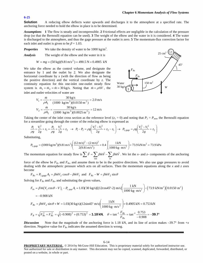
Solution A reducing elbow deflects water upwards and discharges it to the atmosphere at a specified rate. The anchoring force needed to hold the elbow in place is to be determined.
Assumptions 1 The flow is steady and incompressible. 2 Frictional effects are negligible in the calculation of the pressure drop (so that the Bernoulli equation can be used). 3 The weight of the elbow and the water in it is considered. 4 The water is discharged to the atmosphere, and thus the gage pressure at the outlet is zero. 5 The momentum-flux correction factor for each inlet and outlet is given to be = 1.03.
Properties We take the density of water to be 1000 kg/m3.
Analysis The weight of the elbow and the water in it is
kN 0.4905 N 490.5)m/s kg)(9.81 50( 2 mgW
We take the elbow as the control volume, and designate the entrance by 1 and the outlet by 2. We also designate the horizontal coordinate by x (with the direction of flow as being the positive direction) and the vertical coordinate by z. The continuity equation for this one-inlet one-outlet steady flow system is kg/s. 3021 mmm Noting that AVm , the
inlet and outlet velocities of water are
m/s 12)m 0025.0)( kg/m(1000
kg/s30
m/s 0.2)m 0150.0)( kg/m(1000
kg/s30
232
2
231
1
A
mV
A
mV
Taking the center of the inlet cross section as the reference level (z1 = 0) and noting that P2 = Patm, the Bernoulli equation for a streamline going through the center of the reducing elbow is expressed as
2
21
22
gage ,112
21
22
212
222
1
211
2
2
22z
g
VVgPzz
g
VVgPPz
g
V
g
Pz
g
V
g
P
Substituting,
kPa 73.9kN/m 9.73m/skg 1000
kN 14.0
)m/s 81.9(2
m/s) 2(m/s) 12()m/s 81.9)(kg/m 1000( 2
22
2223
gage ,1
P
The momentum equation for steady flow is inout
VmVmF
. We let the x- and z- components of the anchoring
force of the elbow be FRx and FRz, and assume them to be in the positive directions. We also use gage pressures to avoid dealing with the atmospheric pressure which acts on all surfaces. Then the momentum equations along the x and z axes become sinand cos 2121gage1, VmWFVmVmAPF RzRx
Solving for FRx and FRz, and substituting the given values,
2 2
2 1 gage 1 21
1 kN1 03 30 kg/s)[(12cos45 -2) m/s] 73 9 kN/m 0 0150 m
1000 kg m/s
0.908 kN
Rx ,F m V cos V P A . ( . .
kN0.753 kN4905.0m/s kg1000
kN1m/s) in45 kg/s)(12s30(03.1sin
22
WVmFRz
39.7kN 1.18908.0
753.0tantan ,)753.0()908.0( 1-1-2222
Rx
RzRzRxR F
FFFF
Discussion Note that the magnitude of the anchoring force is 1.18 kN, and its line of action makes –39.7 from +x direction. Negative value for FRx indicates the assumed direction is wrong.
Water 30 kg/s
150 m2
25 cm2
45
W 1
2
FRz
FRx
Chapter 6 Momentum Analysis of Flow Systems
PROPRIETARY MATERIAL. © 2014 by McGraw-Hill Education. This is proprietary material solely for authorized instructor use. Not authorized for sale or distribution in any manner. This document may not be copied, scanned, duplicated, forwarded, distributed, or posted on a website, in whole or part.
6-15
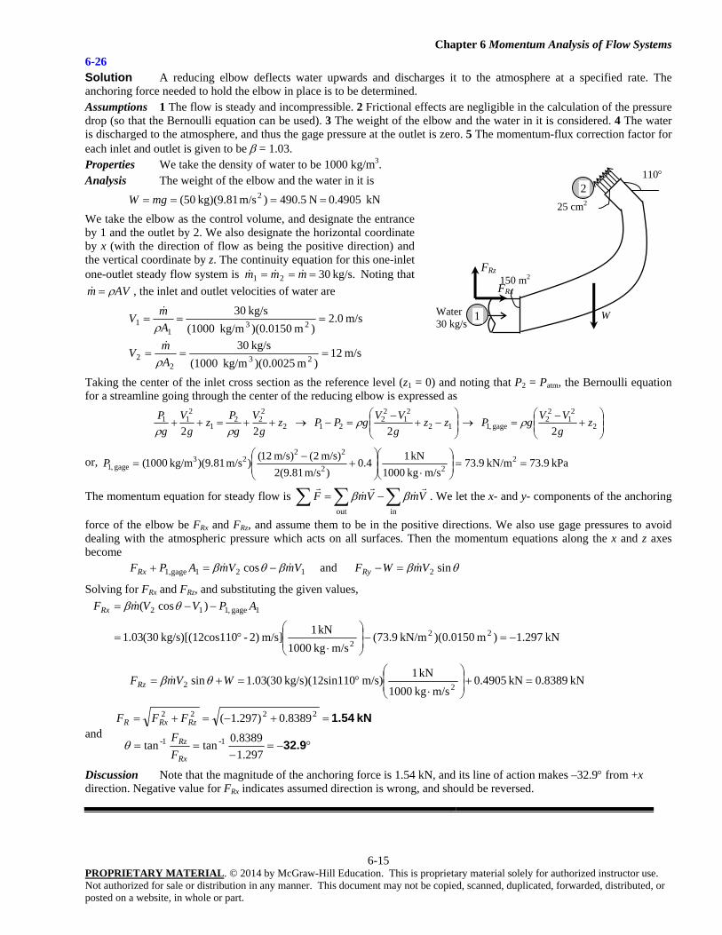
6-26 Solution A reducing elbow deflects water upwards and discharges it to the atmosphere at a specified rate. The anchoring force needed to hold the elbow in place is to be determined. Assumptions 1 The flow is steady and incompressible. 2 Frictional effects are negligible in the calculation of the pressure drop (so that the Bernoulli equation can be used). 3 The weight of the elbow and the water in it is considered. 4 The water is discharged to the atmosphere, and thus the gage pressure at the outlet is zero. 5 The momentum-flux correction factor for each inlet and outlet is given to be = 1.03. Properties We take the density of water to be 1000 kg/m3. Analysis The weight of the elbow and the water in it is
kN 0.4905 N 490.5)m/s kg)(9.81 50( 2 mgW
We take the elbow as the control volume, and designate the entrance by 1 and the outlet by 2. We also designate the horizontal coordinate by x (with the direction of flow as being the positive direction) and the vertical coordinate by z. The continuity equation for this one-inlet one-outlet steady flow system is kg/s. 3021 mmm Noting that
AVm , the inlet and outlet velocities of water are
m/s 12)m 0025.0)( kg/m(1000
kg/s30
m/s 0.2)m 0150.0)( kg/m(1000
kg/s30
232
2
231
1
A
mV
A
mV
Taking the center of the inlet cross section as the reference level (z1 = 0) and noting that P2 = Patm, the Bernoulli equation for a streamline going through the center of the reducing elbow is expressed as
2
21
22
gage ,112
21
22
212
222
1
211
2
2
22z
g
VVgPzz
g
VVgPPz
g
V
g
Pz
g
V
g
P
or, kPa 73.9kN/m 9.73m/skg 1000
kN 14.0
)m/s 81.9(2
m/s) 2(m/s) 12()m/s 81.9)(kg/m 1000( 2
22
2223
gage ,1
P
The momentum equation for steady flow is inout
VmVmF
. We let the x- and y- components of the anchoring
force of the elbow be FRx and FRz, and assume them to be in the positive directions. We also use gage pressures to avoid dealing with the atmospheric pressure which acts on all surfaces. Then the momentum equations along the x and z axes become
sinand cos 2121gage1, VmWFVmVmAPF RyRx
Solving for FRx and FRz, and substituting the given values,
kN 297.1)m 0150.0)(kN/m 9.73(
m/skg 1000
kN 1m/s] 2)-os110kg/s)[(12c 30(03.1
)cos(
222
1gage ,112
APVVmFRx
kN 0.8389kN 4905.0m/skg 1000
kN 1m/s) n110kg/s)(12si 30(03.1sin
22
WVmFRz
and
32.9
kN 1.54
297.1
8389.0tantan
8389.0)297.1(
1-1-
2222
Rx
Rz
RzRxR
F
F
FFF
Discussion Note that the magnitude of the anchoring force is 1.54 kN, and its line of action makes –32.9 from +x direction. Negative value for FRx indicates assumed direction is wrong, and should be reversed.
Water 30 kg/s
150 m2
25 cm2
110
W
FRz
FRx
2
1

Chapter 6 Momentum Analysis of Flow Systems
PROPRIETARY MATERIAL. © 2014 by McGraw-Hill Education. This is proprietary material solely for authorized instructor use. Not authorized for sale or distribution in any manner. This document may not be copied, scanned, duplicated, forwarded, distributed, or posted on a website, in whole or part.
6-16
6-27
Solution Water accelerated by a nozzle strikes the back surface of a cart moving horizontally at a constant velocity. The braking force and the power wasted by the brakes are to be determined.
Assumptions 1 The flow is steady and incompressible. 2 The water splatters off the sides of the plate in all directions in the plane of the back surface. 3 The water jet is exposed to the atmosphere, and thus the pressure of the water jet and the splattered water is the atmospheric pressure which is disregarded since it acts on all surfaces. 4 Fiction during motion is negligible. 5 There is no acceleration of the cart. 7 The motions of the water jet and the cart are horizontal. 6 Jet flow is nearly uniform and thus the effect of the momentum-flux correction factor is negligible, 1.
Analysis We take the cart as the control volume, and the direction of flow as the positive direction of x axis. The relative velocity between the cart and the jet is
m/s 251035cartjet VVVr
Therefore, we can view the cart as being stationary and the jet moving with a velocity of 25 m/s. Noting that water leaves the nozzle at 20 m/s and the corresponding mass flow rate relative to nozzle exit is 30 kg/s, the mass flow rate of water striking the cart corresponding to a water jet velocity of 25 m/s relative to the cart is
kg/s 43.21kg/s) 30(m/s 35
m/s 25jet
jet
mV
Vm r
r
The momentum equation for steady flow in the x (flow) direction reduces in this case to
inout
VmVmF
brake rriiRx VmFVmF
We note that the brake force acts in the opposite direction to flow, and we should not forget the negative sign for forces and velocities in the negative x-direction. Substituting the given values,
N 536
N 8.535
m/skg 1
N 1m/s) 52kg/s)( 43.21(
2brake rrVmF
The negative sign indicates that the braking force acts in the opposite direction to motion, as expected. Noting that work is force times distance and the distance traveled by the cart per unit time is the cart velocity, the power wasted by the brakes is
kW 5.36
W5358
m/sN 1
W1m/s) N)(10 8.535(cartbrakeVFW
Discussion Note that the power wasted is equivalent to the maximum power that can be generated as the cart velocity is maintained constant.
35 m/s
Waterjet
10 m/s
FRx

Chapter 6 Momentum Analysis of Flow Systems
PROPRIETARY MATERIAL. © 2014 by McGraw-Hill Education. This is proprietary material solely for authorized instructor use. Not authorized for sale or distribution in any manner. This document may not be copied, scanned, duplicated, forwarded, distributed, or posted on a website, in whole or part.
6-17
6-28
Solution Water accelerated by a nozzle strikes the back surface of a cart moving horizontally. The acceleration of the cart if the brakes fail is to be determined.
Analysis The braking force was determined in previous problem to be 535.8 N. When the brakes fail, this force will propel the cart forward, and the acceleration will be
2m/s 1.34
N 1
m/skg 1
kg 400
N 8.535 2
cartm
Fa
Discussion This is the acceleration at the moment the brakes fail. The acceleration will decrease as the relative velocity between the water jet and the cart (and thus the force) decreases.
35 m/s
Waterjet
10 m/s
400 kg FRx

Chapter 6 Momentum Analysis of Flow Systems
PROPRIETARY MATERIAL. © 2014 by McGraw-Hill Education. This is proprietary material solely for authorized instructor use. Not authorized for sale or distribution in any manner. This document may not be copied, scanned, duplicated, forwarded, distributed, or posted on a website, in whole or part.
6-18
6-29E
Solution A water jet hits a stationary splitter, such that half of the flow is diverted upward at 45, and the other half is directed down. The force required to hold the splitter in place is to be determined.
Assumptions 1 The flow is steady and incompressible. 2 The water jet is exposed to the atmosphere, and thus the pressure of the water jet before and after the split is the atmospheric pressure which is disregarded since it acts on all surfaces. 3 The gravitational effects are disregarded. 4 The flow is nearly uniform at all cross sections, and thus the effect of the momentum-flux correction factor is negligible, 1.
Properties We take the density of water to be 62.4 lbm/ft3.
Analysis The mass flow rate of water jet is
lbm/s 6240/s)ft )(100lbm/ft 4.62( 33 Vm
We take the splitting section of water jet, including the splitter as the control volume, and designate the entrance by 1 and the outlet of either arm by 2 (both arms have the same velocity and mass flow rate). We also designate the horizontal coordinate by x with the direction of flow as being the positive direction and the vertical coordinate by z.
The momentum equation for steady flow is inout
VmVmF
. We let the x- and y- components of the
anchoring force of the splitter be FRx and FRz, and assume them to be in the positive directions. Noting that V2 = V1 = V and mm
21
2 , the momentum equations along the x and z axes become
00)sin()sin(
)1(coscos)(2
221
221
1221
VmVmF
VmVmVmF
Rz
Rx
Substituting the given values,
2
1 lbf6240 lbm/s (18 ft/s)(cos45 1) 1021 67 lbf
32.2 lbm ft/sRx
Rz
F - .
F
0
-1020 lbf
The negative value for FRx indicates the assumed direction is wrong, and should be reversed. Therefore, a force of 1020 lbf must be applied to the splitter in the opposite direction to flow to hold it in place. No holding force is necessary in the vertical direction. This can also be concluded from the symmetry.
Discussion In reality, the gravitational effects will cause the upper stream to slow down and the lower stream to speed up after the split. But for short distances, these effects are indeed negligible.
100 ft3/s
18 ft/s
45
45
FRz
FRx

Chapter 6 Momentum Analysis of Flow Systems
PROPRIETARY MATERIAL. © 2014 by McGraw-Hill Education. This is proprietary material solely for authorized instructor use. Not authorized for sale or distribution in any manner. This document may not be copied, scanned, duplicated, forwarded, distributed, or posted on a website, in whole or part.
6-19
6-30E
Solution The previous problem is reconsidered. The effect of splitter angle on the force exerted on the splitter as the half splitter angle varies from 0 to 180 in increments of 10 is to be investigated.
Analysis The EES Equations window is printed below, followed by the tabulated and plotted results.
g=32.2 "ft/s2"
rho=62.4 "lbm/ft3"
V_dot=100 "ft3/s"
V=20 "ft/s"
m_dot=rho*V_dot
F_R=-m_dot*V*(cos(theta)-1)/g "lbf"
, m , lbm/s FR, lbf
0
10
20
30
40
50
60
70
80
90
100
110
120
130
140
150
160
170
180
6240
6240
6240
6240
6240
6240
6240
6240
6240
6240
6240
6240
6240
6240
6240
6240
6240
6240
6240
0
59
234
519
907
1384
1938
2550
3203
3876
4549
5201
5814
6367
6845
7232
7518
7693
7752
Discussion The force rises from zero at = 0o to a maximum at = 180o, as expected, but the relationship is not linear.
Chapter 6 Momentum Analysis of Flow Systems
PROPRIETARY MATERIAL. © 2014 by McGraw-Hill Education. This is proprietary material solely for authorized instructor use. Not authorized for sale or distribution in any manner. This document may not be copied, scanned, duplicated, forwarded, distributed, or posted on a website, in whole or part.
6-20
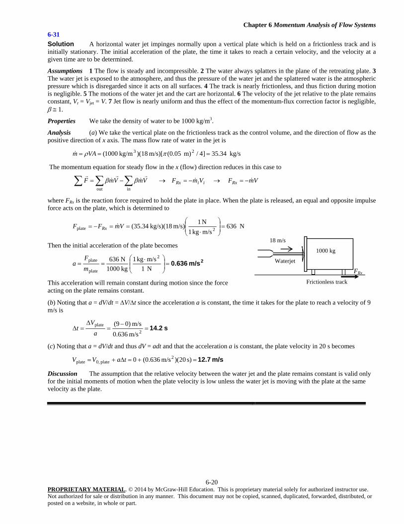
6-31
Solution A horizontal water jet impinges normally upon a vertical plate which is held on a frictionless track and is initially stationary. The initial acceleration of the plate, the time it takes to reach a certain velocity, and the velocity at a given time are to be determined.
Assumptions 1 The flow is steady and incompressible. 2 The water always splatters in the plane of the retreating plate. 3 The water jet is exposed to the atmosphere, and thus the pressure of the water jet and the splattered water is the atmospheric pressure which is disregarded since it acts on all surfaces. 4 The track is nearly frictionless, and thus fiction during motion is negligible. 5 The motions of the water jet and the cart are horizontal. 6 The velocity of the jet relative to the plate remains constant, Vr = Vjet = V. 7 Jet flow is nearly uniform and thus the effect of the momentum-flux correction factor is negligible, 1.
Properties We take the density of water to be 1000 kg/m3.
Analysis (a) We take the vertical plate on the frictionless track as the control volume, and the direction of flow as the positive direction of x axis. The mass flow rate of water in the jet is
kg/s35.34]4/m) (0.05m/s)[ )(18 kg/m1000( 23 VAm
The momentum equation for steady flow in the x (flow) direction reduces in this case to
inout
VmVmF
VmFVmF RxiiRx
where FRx is the reaction force required to hold the plate in place. When the plate is released, an equal and opposite impulse force acts on the plate, which is determined to
N 636m/s kg1
N 1m/s) kg/s)(1834.35(
2plate
VmFF Rx
Then the initial acceleration of the plate becomes
2m/s 0.636
N 1
m/s kg1
kg1000
N 636 2
plate
plate
m
Fa
This acceleration will remain constant during motion since the force acting on the plate remains constant.
(b) Noting that a = dV/dt = V/t since the acceleration a is constant, the time it takes for the plate to reach a velocity of 9 m/s is
s 14.2
2
plate
m/s 636.0
m/s )09(
a
Vt
(c) Noting that a = dV/dt and thus dV = adt and that the acceleration a is constant, the plate velocity in 20 s becomes
m/s 12.7 s) 20)(m/s 636.0(0 2plate 0,plate taVV
Discussion The assumption that the relative velocity between the water jet and the plate remains constant is valid only for the initial moments of motion when the plate velocity is low unless the water jet is moving with the plate at the same velocity as the plate.
18 m/s
Waterjet
1000 kg
Frictionless track
FRx

Chapter 6 Momentum Analysis of Flow Systems
PROPRIETARY MATERIAL. © 2014 by McGraw-Hill Education. This is proprietary material solely for authorized instructor use. Not authorized for sale or distribution in any manner. This document may not be copied, scanned, duplicated, forwarded, distributed, or posted on a website, in whole or part.
6-21
6-32E
Solution A fan moves air at sea level at a specified rate. The force required to hold the fan and the minimum power input required for the fan are to be determined.
Assumptions 1 The flow of air is steady and incompressible. 2 Standard atmospheric conditions exist so that the pressure at sea level is 1 atm. 3 Air leaves the fan at a uniform velocity at atmospheric pressure. 4 Air approaches the fan through a large area at atmospheric pressure with negligible velocity. 5 The frictional effects are negligible, and thus the entire mechanical power input is converted to kinetic energy of air (no conversion to thermal energy through frictional effects). 6 Wind flow is nearly uniform and thus the momentum-flux correction factor can be taken to be unity, 1.
Properties The gas constant of air is R = 0.3704 psift3/lbmR. The standard atmospheric pressure at sea level is 1 atm = 14.7 psi.
Analysis (a) We take the control volume to be a horizontal hyperbolic cylinder bounded by streamlines on the sides with air entering through the large cross-section (section 1) and the fan located at the narrow cross-section at the end (section 2), and let its centerline be the x axis. The density, mass flow rate, and discharge velocity of air are
33
lbm/ft 0749.0R) R)(530/lbmftpsi (0.3704
psi 7.14
RT
P
lbm/s 2.50lbm/min 8.149/min)ft 2000)(lbm/ft 0749.0( 33 V m
ft/s 10.6ft/min 6.6364/ft) 2(
/minft 2000
4/ 2
3
222
2 DA
VVV
The momentum equation for steady flow is inout
VmVmF
. Letting the reaction force to hold the fan be FRx
and assuming it to be in the positive x (i.e., the flow) direction, the momentum equation along the x axis becomes
2 2
1 lbf( ) 0 (2.50 lbm/s)(10.6 ft/s)
32.2 lbm ft/sRxF m V mV
0.820 lbf
Therefore, a force of 0.82 lbf must be applied (through friction at the base, for example) to prevent the fan from moving in the horizontal direction under the influence of this force.
(b) Noting that P1 = P2 = Patm and V1 0, the energy equation for the selected control volume reduces to
lossmech,turbine2
222
upump,1
211
22EWgz
VPmWgz
VPm
2
22
ufan,V
mW
Substituting,
W 5.91
ft/slbf 0.73756
W1
ft/slbm 2.32
lbf 1
2
ft/s) (10.6lbm/s) 50.2(
2 2
222
ufan,V
mW
Therefore, a useful mechanical power of 5.91 W must be supplied to air. This is the minimum required power input required for the fan.
Discussion The actual power input to the fan will be larger than 5.91 W because of the fan inefficiency in converting mechanical power to kinetic energy.
2000 cfm
24 in
Fan
12

Chapter 6 Momentum Analysis of Flow Systems
PROPRIETARY MATERIAL. © 2014 by McGraw-Hill Education. This is proprietary material solely for authorized instructor use. Not authorized for sale or distribution in any manner. This document may not be copied, scanned, duplicated, forwarded, distributed, or posted on a website, in whole or part.
6-22
6-33E
Solution A horizontal water jet strikes a bent plate, which deflects the water by 135 from its original direction. The force required to hold the plate against the water stream is to be determined.
Assumptions 1 The flow is steady and incompressible. 2 The water jet is exposed to the atmosphere, and thus the pressure of the water jet and the splattered water is the atmospheric pressure, which is disregarded since it acts on all surfaces. 3 Frictional and gravitational effects are negligible. 4 There is no splattering of water or the deformation of the jet, and the reversed jet leaves at the same velocity and flow rate. 5 Jet flow is nearly uniform and thus the momentum-flux correction factor is nearly unity, 1.
Properties We take the density of water to be 62.4 lbm/ft3.
Analysis We take the plate together with the curved water jet as the control volume, and designate the jet inlet by 1 and the outlet by 2. We also designate the horizontal coordinate by x (with the direction of incoming flow as being the positive direction), and the vertical coordinate by z. The equation of conservation of mass for this one-inlet one-outlet steady flow system is mmm 21 where
lbm/s 8.428]4/ft) 12/3([ft/s) 140)(lbm/ft (62.4]4/[ 232 DVVAm
The momentum equation for steady flow is inout
VmVmF
. We let the x- and z- components of the anchoring
force of the plate be FRx and FRz, and assume them to be in the positive directions. Then the momentum equations along the x and y axes become
45sin45sin)(
)45cos1()(45cos)(
2
12
VmVmF
VmVmVmF
Rz
Rx
Substituting the given values,
2
1 lbf(428.8 lbm/s)(140 ft/s)(1 cos45 )
32.2 lbm ft/s
3182.64 lbf 3180 lbf
RxF
2
1 lbf(428.8 lbm/s)(140 ft/s)sin45 1318.29 lbf 1320 lbf
32.2 lbm ft/sRzF
and
22 2 2 -1 1 1318 293182 64 1318 29 3444 86 lbf tan tan 157 50
3182 64Ry -
R Rx RzRx
F .F F F . . . .
F .
,3440 lbf 158
Discussion Note that the magnitude of the anchoring force is 3440 lbf, and its line of action is 158 from the positive x direction. Also, a negative value for FRx indicates the assumed direction is wrong; the actual anchoring force is to the left. This makes sense when we think about it; with the water jet striking the plate from left to right, one would have to push to the left in order to hold the plat in place.
140 ft/s
Waterjet
135
3 in
2
1
FRz
FRx

Chapter 6 Momentum Analysis of Flow Systems
PROPRIETARY MATERIAL. © 2014 by McGraw-Hill Education. This is proprietary material solely for authorized instructor use. Not authorized for sale or distribution in any manner. This document may not be copied, scanned, duplicated, forwarded, distributed, or posted on a website, in whole or part.
6-23
6-34
Solution Firemen are holding a nozzle at the end of a hose while trying to extinguish a fire. The average water outlet velocity and the resistance force required of the firemen to hold the nozzle are to be determined.
Assumptions 1 The flow is steady and incompressible. 2 The water jet is exposed to the atmosphere, and thus the pressure of the water jet is the atmospheric pressure, which is disregarded since it acts on all surfaces. 3 Gravitational effects and vertical forces are disregarded since the horizontal resistance force is to be determined. 5 Jet flow is nearly uniform and thus the momentum-flux correction factor can be taken to be unity, 1.
Properties We take the density of water to be 1000 kg/m3.
Analysis (a) We take the nozzle and the horizontal portion of the hose as the system such that water enters the control volume vertically and outlets horizontally (this way the pressure force and the momentum flux at the inlet are in the vertical direction, with no contribution to the force balance in the horizontal direction), and designate the entrance by 1 and the outlet by 2. We also designate the horizontal coordinate by x (with the direction of flow as being the positive direction). The average outlet velocity and the mass flow rate of water are determined from
m/s 39.8 m/s 39.79m/min 23874/m) 08.0(
/minm 12
4/ 2
3
2 DAV
VV
kg/s 200kg/min 000,12/min)m )(12kg/m 1000( 33 V m
(b) The momentum equation for steady flow is inout
VmVmF
. We let horizontal force applied by the firemen
to the nozzle to hold it be FRx, and assume it to be in the positive x direction. Then the momentum equation along the x direction gives
N 7958
2m/skg 1
N 1m/s) 9kg/s)(39.7 200(0 VmVmF eRx
Therefore, the firemen must be able to resist a force of 7958 N to hold the nozzle in place.
Discussion The force of 7958 N is equivalent to the weight of about 810 kg. That is, holding the nozzle requires the strength of holding a weight of 810 kg, which cannot be done by a single person. This demonstrates why several firemen are used to hold a hose with a high flow rate.
12 m3/min
FRz
FRx

Chapter 6 Momentum Analysis of Flow Systems
PROPRIETARY MATERIAL. © 2014 by McGraw-Hill Education. This is proprietary material solely for authorized instructor use. Not authorized for sale or distribution in any manner. This document may not be copied, scanned, duplicated, forwarded, distributed, or posted on a website, in whole or part.
6-24
6-35
Solution A horizontal jet of water with a given velocity strikes a flat plate that is moving in the same direction at a specified velocity. The force that the water stream exerts against the plate is to be determined.
Assumptions 1 The flow is steady and incompressible. 2 The water splatters in all directions in the plane of the plate. 3 The water jet is exposed to the atmosphere, and thus the pressure of the water jet and the splattered water is the atmospheric pressure, which is disregarded since it acts on all surfaces. 4 The vertical forces and momentum fluxes are not considered since they have no effect on the horizontal force exerted on the plate. 5 The velocity of the plate, and the velocity of the water jet relative to the plate, are constant. 6 Jet flow is nearly uniform and thus the momentum-flux correction factor can be taken to be unity, 1.
Properties We take the density of water to be 1000 kg/m3.
Analysis We take the plate as the control volume, and the flow direction as the positive direction of x axis. The relative velocity between the plate and the jet is
m/s 301040platejet VVVr
Therefore, we can view the plate as being stationary and the jet to be moving with a velocity of 30 m/s. The mass flow rate of water relative to the plate [i.e., the flow rate at which water strikes the plate] is
kg/s 90.584
m) (0.05m/s) 30)(kg/m 1000(
4
23
2
D
VAVm rrr
The momentum equation for steady flow is inout
VmVmF
. We let the horizontal reaction force applied to the
plate in the negative x direction to counteract the impulse of the water jet be FRx. Then the momentum equation along the x direction gives
N 1767
2m/s1kg
N 1m/s) kg/s)(30 90.58( 0 rrRxiRx VmFVmF
Therefore, the water jet applies a force of 1767 N on the plate in the direction of motion, and an equal and opposite force must be applied on the plate if its velocity is to remain constant.
Discussion Note that we used the relative velocity in the determination of the mass flow rate of water in the momentum analysis since water will enter the control volume at this rate. (In the limiting case of the plate and the water jet moving at the same velocity, the mass flow rate of water relative to the plate will be zero since no water will be able to strike the plate).
40 m/s
Waterjet
10 m/s
5 cm
FRx
Chapter 6 Momentum Analysis of Flow Systems
PROPRIETARY MATERIAL. © 2014 by McGraw-Hill Education. This is proprietary material solely for authorized instructor use. Not authorized for sale or distribution in any manner. This document may not be copied, scanned, duplicated, forwarded, distributed, or posted on a website, in whole or part.
6-25
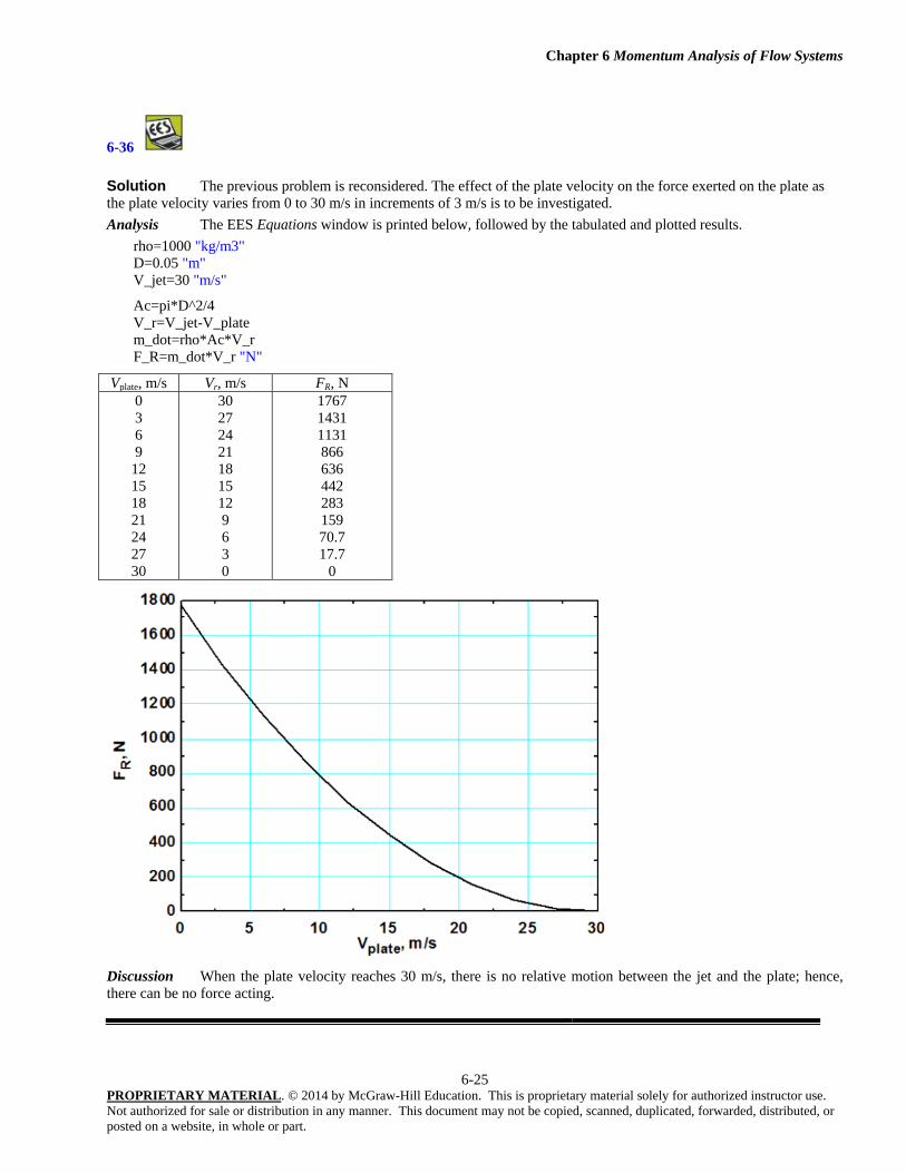
6-36
Solution The previous problem is reconsidered. The effect of the plate velocity on the force exerted on the plate as the plate velocity varies from 0 to 30 m/s in increments of 3 m/s is to be investigated.
Analysis The EES Equations window is printed below, followed by the tabulated and plotted results.
rho=1000 "kg/m3" D=0.05 "m" V_jet=30 "m/s"
Ac=pi*D^2/4 V_r=V_jet-V_plate m_dot=rho*Ac*V_r F_R=m_dot*V_r "N"
Vplate, m/s Vr, m/s FR, N 0 3 6 9
12 15 18 21 24 27 30
30 27 24 21 18 15 12 9 6 3 0
1767 1431 1131 866 636 442 283 159 70.7 17.7
0
Discussion When the plate velocity reaches 30 m/s, there is no relative motion between the jet and the plate; hence, there can be no force acting.

Chapter 6 Momentum Analysis of Flow Systems
PROPRIETARY MATERIAL. © 2014 by McGraw-Hill Education. This is proprietary material solely for authorized instructor use. Not authorized for sale or distribution in any manner. This document may not be copied, scanned, duplicated, forwarded, distributed, or posted on a website, in whole or part.
6-26
6-37E
Solution A horizontal water jet strikes a curved plate, which deflects the water back to its original direction. The force required to hold the plate against the water stream is to be determined.
Assumptions 1 The flow is steady and incompressible. 2 The water jet is exposed to the atmosphere, and thus the pressure of the water jet and the splattered water is the atmospheric pressure, which is disregarded since it acts on all surfaces. 3 Friction between the plate and the surface it is on is negligible (or the friction force can be included in the required force to hold the plate). 4 There is no splashing of water or the deformation of the jet, and the reversed jet leaves horizontally at the same velocity and flow rate. 5 Jet flow is nearly uniform and thus the momentum-flux correction factor is nearly unity, 1.
Properties We take the density of water to be 62.4 lbm/ft3.
Analysis We take the plate together with the curved water jet as the control volume, and designate the jet inlet by 1 and the outlet by 2. We also designate the horizontal coordinate by x (with the direction of incoming flow as being the positive direction). The continuity equation for this one-inlet one-outlet steady flow system is mmm 21 where
lbm/s 7.275]4/ft) 12/3([ft/s) 90)(lbm/ft (62.4]4/[ 232 DVVAm
The momentum equation for steady flow is inout
VmVmF
. Letting the reaction force to hold the plate be FRx
and assuming it to be in the positive direction, the momentum equation along the x axis becomes
VmVmVmFRx 2)()( 12
Substituting,
lbf 1540
lbf 1541ft/slbm 32.2
lbf 1ft/s) lbm/s)(90 7.275(2
2RxF
Therefore, a force of 1540 lbf must be applied on the plate in the negative x direction to hold it in place.
Discussion Note that a negative value for FRx indicates the assumed direction is wrong (as expected), and should be reversed. Also, there is no need for an analysis in the vertical direction since the fluid streams are horizontal.
Waterjet
90 ft/s
90 ft/s
3 in 1
2
FRx

Chapter 6 Momentum Analysis of Flow Systems
PROPRIETARY MATERIAL. © 2014 by McGraw-Hill Education. This is proprietary material solely for authorized instructor use. Not authorized for sale or distribution in any manner. This document may not be copied, scanned, duplicated, forwarded, distributed, or posted on a website, in whole or part.
6-27
6-38 Solution A helicopter hovers at sea level while being loaded. The volumetric air flow rate and the required power input during unloaded hover, and the rpm and the required power input during loaded hover are to be determined. Assumptions 1 The flow of air is steady and incompressible. 2 Air leaves the blades at a uniform velocity at atmospheric pressure. 3 Air approaches the blades from the top through a large area at atmospheric pressure with negligible velocity. 4 The frictional effects are negligible, and thus the entire mechanical power input is converted to kinetic energy of air (no conversion to thermal energy through frictional effects). 5 The change in air pressure with elevation is negligible because of the low density of air. 6 There is no acceleration of the helicopter, and thus the lift generated is equal to the total weight. 7 Air flow is nearly uniform and thus the momentum-flux correction factor can be taken to be unity, 1. Properties The density of air is given to be 1.18 kg/m3. Analysis (a) We take the control volume to be a vertical hyperbolic cylinder bounded by streamlines on the sides with air entering through the large cross-section (section 1) at the top and the fan located at the narrow cross-section at the bottom (section 2), and let its centerline be the z axis with upwards being the positive direction.
The momentum equation for steady flow is inout
VmVmF
. Noting that the only force acting on the
control volume is the total weight W and it acts in the negative z direction, the momentum equation along the z axis gives
)( 0)( 22
22222 A
WVAVVAVVmWVmW
where A is the blade span area, 222 m 5.2544/m) 18(4/ DA
Then the discharge velocity, volume flow rate, and the mass flow rate of air in the unloaded mode become
m/s 80.19)m )(254.5kg/m (1.18
)m/s kg)(9.81 000,12(23
2unloaded
unloaded,2 A
gmV
/sm 5039 3 m/s) 80.19)(m 5.254( 2unloaded,2unloaded AVV
kg/s 5946/s)m 5039)(kg/m 18.1( 33unloadedunloaded V m
Noting that P1 = P2 = Patm, V1 0, the elevation effects are negligible, and the frictional effects are disregarded, the energy equation for the selected control volume reduces to
lossmech,turbine2
222
upump,1
211
22EWgz
VPmWgz
VPm
2
22
ufan,V
mW
Substituting,
kW 1170
kW 1165
m/skN 1
kW 1
m/skg 1000
kN 1
2
m/s) (19.80kg/s) 5946(
2 2
2
unloaded
22
ufan, unloadedV
mW
(b) We now repeat the calculations for the loaded helicopter, whose mass is 12,000+14,000 = 26,000 kg:
m/s 14.29)m )(254.5kg/m (1.18
)m/s kg)(9.81 000,26(23
2loaded
loaded,2 A
gmV
kg/s 8752m/s) 14.29)(m 5.254)(kg/m 18.1( 23loaded 2,loadedloaded AVm V
kW 3720
kW 3716
m/skN 1
kW 1
m/skg 1000
kN 1
2
m/s) (29.14kg/s) 8752(
2 2
2
loaded
22
ufan, loadedV
mW
Noting that the average flow velocity is proportional to the overhead blade rotational velocity, the rpm of the loaded helicopter blades becomes
rpm 809 rpm) 550(80.19
14.29 unloaded
unloaded2,
loaded2,loaded
unloaded
loaded
unloaded2,
loaded2,2 n
V
Vn
n
n
V
VnkV
Discussion The actual power input to the helicopter blades will be considerably larger than the calculated power input because of the fan inefficiency in converting mechanical power to kinetic energy.
18 m
Load 14,000 kg
Sea level
1
2

Chapter 6 Momentum Analysis of Flow Systems
PROPRIETARY MATERIAL. © 2014 by McGraw-Hill Education. This is proprietary material solely for authorized instructor use. Not authorized for sale or distribution in any manner. This document may not be copied, scanned, duplicated, forwarded, distributed, or posted on a website, in whole or part.
6-28
6-39
Solution A helicopter hovers on top of a high mountain where the air density considerably lower than that at sea level. The blade rotational velocity to hover at the higher altitude and the percent increase in the required power input to hover at high altitude relative to that at sea level are to be determined.
Assumptions 1 The flow of air is steady and incompressible. 2 The air leaves the blades at a uniform velocity at atmospheric pressure. 3 Air approaches the blades from the top through a large area at atmospheric pressure with negligible velocity. 4 The frictional effects are negligible, and thus the entire mechanical power input is converted to kinetic energy of air. 5 The change in air pressure with elevation while hovering at a given location is negligible because of the low density of air. 6 There is no acceleration of the helicopter, and thus the lift generated is equal to the total weight. 7 Air flow is nearly uniform and thus the momentum-flux correction factor can be taken to be unity, 1.
Properties The density of air is given to be 1.18 kg/m3 at sea level, and 0.928 kg/m3 on top of the mountain.
Analysis (a) We take the control volume to be a vertical hyperbolic cylinder bounded by streamlines on the sides with air entering through the large cross-section (section 1) at the top and the fan located at the narrow cross-section at the bottom (section 2), and let its centerline be the z axis with upwards being the positive direction.
The momentum equation for steady flow is inout
VmVmF
. Noting that the only force acting on the
control volume is the total weight W and it acts in the negative z direction, the momentum equation along the z axis gives
)( 0)( 22
22222 A
WVAVVAVVmWVmW
where A is the blade span area. Then for a given weight W, the ratio of discharge velocities becomes
32,mountain mountain sea
32,sea mountainsea
/ 1.18 kg/m1.1276
0.928 kg/m/
V W A
V W A
Noting that the average flow velocity is proportional to the overhead blade rotational velocity, the rpm of the helicopter blades on top of the mountain becomes
rpm 620 rpm 620.2rpm) 550)(1276.1( seasea2,
mountain2,mountain
sea2,
mountain2,
sea
mountain2 n
V
Vn
V
V
n
nkVn
Noting that P1 = P2 = Patm, V1 0, the elevation effect are negligible, and the frictional effects are disregarded, the energy equation for the selected control volume reduces to
lossmech,turbine2
222
upump,1
211
22EWgz
VPmWgz
VPm
2
22
ufan,V
mW
or A
W
A
WA
A
WA
VA
VAV
VmW
2222
5.15.1
21
3
21
32
22
2
22
ufan,
Then the ratio of the required power input on top of the mountain to that at sea level becomes
128.1kg/m 0.928
kg/m 1.18
/5.0
/5.03
3
mountain
sea
sea5.1
mountain5.1
ufan, sea
ufan,mountain
AW
AW
W
W
Therefore, the required power input will increase by approximately 12.8% on top of the mountain relative to the sea level.
Discussion Note that both the rpm and the required power input to the helicopter are inversely proportional to the square root of air density. Therefore, more power is required at higher elevations for the helicopter to operate because air is less dense, and more air must be forced by the blades into the downdraft.
18 m
Load 14,000 kg
Sea level
1
2

Chapter 6 Momentum Analysis of Flow Systems
PROPRIETARY MATERIAL. © 2014 by McGraw-Hill Education. This is proprietary material solely for authorized instructor use. Not authorized for sale or distribution in any manner. This document may not be copied, scanned, duplicated, forwarded, distributed, or posted on a website, in whole or part.
6-29
6-40
Solution Water flowing in a pipe is slowed down by a diffuser. The force exerted on the bolts due to water flow is to be determined.
Assumptions 1 The flow is steady and incompressible. 2 Frictional effects are negligible (so that the Bernoulli equation can be used). 3 The water is discharged to the atmosphere, and thus the gage pressure at the outlet is zero.
Properties We take the density of water to be 1000 kg/m3.
Analysis
(2)
(1) y
Fbolts P2=0
x
Writing Bernoulli equation between 1-2 ;
lossesnegligiblezVPzVP 22
2212
11 2
1
2
1
73.12
41.0
1.021
V m/s , 18.3
42.0
1.022
V m/s
PaVVP 7597018.373.1210002
1
2
1 2221
221
Applying linear momentum to the CV gives;
boltsx
cscv
FAPAVVAVVandFdAnVVdVt
11222111 V
boltsFAPVVQ 1112
73.1218.31.010004
1.075970
2
boltsF
1552boltsF ,fluid force on bolts 1552 N to right.
d=10 cmD=20 cm
Diffuser

Chapter 6 Momentum Analysis of Flow Systems
PROPRIETARY MATERIAL. © 2014 by McGraw-Hill Education. This is proprietary material solely for authorized instructor use. Not authorized for sale or distribution in any manner. This document may not be copied, scanned, duplicated, forwarded, distributed, or posted on a website, in whole or part.
6-30
6-41
Solution The weight of a water tank is balanced by a counterweight. Water enters the tank horizontally and there is a hole at the bottom of the tank. The amount of mass that must be added to or removed from the counterweight to maintain balance when the hole at the bottom is opened is to be determined.
Properties We take the density of water to be 1000 kg/m3.
Analysis
The flowrate from the hole, just after the valve is opened,
smghCAQ h /1054.35.081.924
04.090.02 33
2
smVhole /82.25.081.9290.0
Reaction force due to momentum change
NQVF h 1082.21054.31000 3
Therefore the tank will sink just after the valve is opened, thus m = 81.9
10 1 kg must be removed from the counterweight.

Chapter 6 Momentum Analysis of Flow Systems
PROPRIETARY MATERIAL. © 2014 by McGraw-Hill Education. This is proprietary material solely for authorized instructor use. Not authorized for sale or distribution in any manner. This document may not be copied, scanned, duplicated, forwarded, distributed, or posted on a website, in whole or part.
6-31
6-42
Solution A wind turbine with a given span diameter and efficiency is subjected to steady winds. The power generated and the horizontal force on the supporting mast of the turbine are to be determined.
Assumptions 1 The wind flow is steady and incompressible. 2 The efficiency of the turbine-generator is independent of wind speed. 3 The frictional effects are negligible, and thus none of the incoming kinetic energy is converted to thermal energy. 4 Wind flow is uniform and thus the momentum-flux correction factor is nearly unity, 1.
Properties The density of air is given to be 1.25 kg/m3.
Analysis (a) The power potential of the wind is its kinetic
energy, which is V2/2 per unit mass, and 2/2Vm for a given mass flow rate:
m/s 333.8km/h 6.3
m/s 1km/h) 30(1
V
kg/s 452,294
m) (60m/s) 333.8)(kg/m 25.1(
4
23
2
11111
D
VAVm
kW 1023m/skN 1
kW 1
m/skg 1000
kN 1
2
m/s) (8.333kg/s) 452,29(
2 2
221
1max
VmkemW
Then the actual power produced becomes
kW 327 kW) 1023)(32.0(max turbinewindact WW
(b) The frictional effects are assumed to be negligible, and thus the portion of incoming kinetic energy not converted to electric power leaves the wind turbine as outgoing kinetic energy. Therefore,
)1(2
2
)1( newind turbi
21
22
newind turbi12 V
mV
mkemkem
or
m/s 872.60.321m/s) 333.8(1 turbinewind12 VV
We choose the control volume around the wind turbine such that the wind is normal to the control surface at the inlet and the outlet, and the entire control surface is at the atmospheric pressure. The momentum equation for steady flow is
inout
VmVmF
. Writing it along the x-direction (without forgetting the negative sign for forces and velocities
in the negative x-direction) and assuming the flow velocity through the turbine to be equal to the wind velocity give
kN 43.0
21212m/skg 1000
kN 1m/s) 333.82kg/s)(6.87 452,29()( VVmVmVmFR
The negative sign indicates that the reaction force acts in the negative x direction, as expected.
Discussion This force acts on top of the tower where the wind turbine is installed, and the bending moment it generates at the bottom of the tower is obtained by multiplying this force by the tower height.
Wind
V1
FR
V2 D
1 2

Chapter 6 Momentum Analysis of Flow Systems
PROPRIETARY MATERIAL. © 2014 by McGraw-Hill Education. This is proprietary material solely for authorized instructor use. Not authorized for sale or distribution in any manner. This document may not be copied, scanned, duplicated, forwarded, distributed, or posted on a website, in whole or part.
6-32
6-43
Solution Water enters a centrifugal pump axially at a specified rate and velocity, and leaves in the normal direction along the pump casing. The force acting on the shaft in the axial direction is to be determined.
Properties We take the density of water to be 1000 kg/m3.
Assumptions 1 The flow is steady and incompressible. 2 The forces acting on the piping system in the horizontal direction are negligible. 3 The atmospheric pressure is disregarded since it acts on all surfaces.
Analysis We take the pump as the control volume, and the inlet direction of flow as the positive direction of x axis. The momentum equation for steady flow in the x (flow) direction reduces in this case to
inout
VmVmF
iiRxiRx VVmFVmF V
Note that the reaction force acts in the opposite direction to flow, and we should not forget the negative sign for forces and velocities in the negative x-direction. Substituting the given values,
N 450
233
brakem/skg 1
N 1m/s) /s)(5m )(0.09kg/m 1000(F
Discussion To find the total force acting on the shaft, we also need to do a force balance for the vertical direction, and find the vertical component of the reaction force.
0.09 m3/s 5 m/s
FRx mV
z
x

Chapter 6 Momentum Analysis of Flow Systems
PROPRIETARY MATERIAL. © 2014 by McGraw-Hill Education. This is proprietary material solely for authorized instructor use. Not authorized for sale or distribution in any manner. This document may not be copied, scanned, duplicated, forwarded, distributed, or posted on a website, in whole or part.
6-33
6-44
Solution A curved duct deflects a fluid. The horizontal force exerted on the duct by the fluid is to be determined.
Assumptions 1 The flow is steady and incompressible. 2 The momentum-flux correction factor for each inlet and outlet is given to account for frictional effects and the non-uniformity of the inlet and outlet velocity profiles.
Properties The density of the liquid is = 998.2 kg/m3. Viscosity does not enter our analysis.
Analysis (a) We take the fluid within the duct as the control volume (see sketch), and designate the inlet by 1 and the outlet by 2. We also designate the horizontal coordinate by x (with the direction of flow as being the positive direction). Conservation of mass for this one-inlet one-outlet steady flow system is 1 2m m m . The mass flow rate is
1 1 2 2m V A V A , and the average speed at the outlet is thus
1 1 1 12
2 2 2
V A V AmV
A A A
. Since A1 = A2 in this problem, V2= V1. The momentum equation for steady flow in the x-
direction is on CVout in
xF mu mu , where u is the horizontal velocity component: u1 = V1 and u2 = -V1. The total
force on the control volume consists of pressure forces at the inlet and outlet plus the total of all forces (including pressure and viscous forces) acting on the control volume by the duct walls. Calling this force Fx, duct on fluid, and assuming it to be in the positive x-direction, we write
1,gage 1 2,gage 2 , duct on fluid 2 1 1 1xP A P A F m V m V
Note that we must be careful with the signs for forces (including pressure forces) and velocities. Solving for Fx, duct on fluid, and plugging in 1 1m V A , we get
2, duct on fluid 1,gage 2,gage 1 1 1 1 2xF P P A V A
Finally, the force exerted by the fluid on the duct is the negative of this, i.e.,
2, fluid on duct , duct on fluid 1,gage 2,gage 1 1 1 1 2x x xF F F P P A V A
(b) We verify our expression by plugging in the given values:
2
2 22 2 3 2
N N kg m N78470 65230 0.025 m 998.2 10 0.025 m 1.01 1.03
m m m s kg m/s
8683.3 N
xF
8680 N
where we give the final answer to three significant digits in keeping with our convention.
Discussion The direction agrees with our intuition. The fluid is trying to push the duct to the right. A negative value for Fx, fluid on duct indicates that the initially assumed direction was incorrect, but did not hinder our solution.
V1 1
P1,gage A1
V2 2
P2,gage
Fx, duct on fluid
1
2
CV
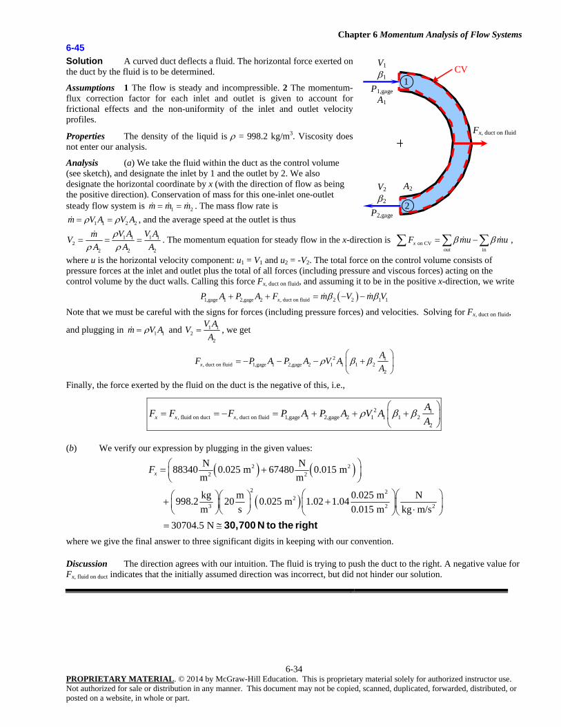
Chapter 6 Momentum Analysis of Flow Systems
PROPRIETARY MATERIAL. © 2014 by McGraw-Hill Education. This is proprietary material solely for authorized instructor use. Not authorized for sale or distribution in any manner. This document may not be copied, scanned, duplicated, forwarded, distributed, or posted on a website, in whole or part.
6-34
6-45
Solution A curved duct deflects a fluid. The horizontal force exerted on the duct by the fluid is to be determined.
Assumptions 1 The flow is steady and incompressible. 2 The momentum-flux correction factor for each inlet and outlet is given to account for frictional effects and the non-uniformity of the inlet and outlet velocity profiles.
Properties The density of the liquid is = 998.2 kg/m3. Viscosity does not enter our analysis.
Analysis (a) We take the fluid within the duct as the control volume (see sketch), and designate the inlet by 1 and the outlet by 2. We also designate the horizontal coordinate by x (with the direction of flow as being the positive direction). Conservation of mass for this one-inlet one-outlet steady flow system is 1 2m m m . The mass flow rate is
1 1 2 2m V A V A , and the average speed at the outlet is thus
1 1 1 12
2 2 2
V A V AmV
A A A
. The momentum equation for steady flow in the x-direction is on CVout in
xF mu mu ,
where u is the horizontal velocity component: u1 = V1 and u2 = -V2. The total force on the control volume consists of pressure forces at the inlet and outlet plus the total of all forces (including pressure and viscous forces) acting on the control volume by the duct walls. Calling this force Fx, duct on fluid, and assuming it to be in the positive x-direction, we write
1,gage 1 2,gage 2 , duct on fluid 2 2 1 1xP A P A F m V m V
Note that we must be careful with the signs for forces (including pressure forces) and velocities. Solving for Fx, duct on fluid,
and plugging in 1 1m V A and 1 12
2
V AV
A , we get
2 1, duct on fluid 1,gage 1 2,gage 2 1 1 1 2
2x
AF P A P A V A
A
Finally, the force exerted by the fluid on the duct is the negative of this, i.e.,
2 1, fluid on duct , duct on fluid 1,gage 1 2,gage 2 1 1 1 2
2x x x
AF F F P A P A V A
A
(b) We verify our expression by plugging in the given values:
2 22 2
2 22
3 2 2
N N88340 0.025 m 67480 0.015 m
m m
kg m 0.025 m N 998.2 20 0.025 m 1.02 1.04
m s 0.015 m kg m/s
30704.5 N
xF
30,700 N to the right
where we give the final answer to three significant digits in keeping with our convention.
Discussion The direction agrees with our intuition. The fluid is trying to push the duct to the right. A negative value for Fx, fluid on duct indicates that the initially assumed direction was incorrect, but did not hinder our solution.
V1 1
P1,gage A1
V2 2
P2,gage
Fx, duct on fluid
1
2
CV
A2

Chapter 6 Momentum Analysis of Flow Systems
PROPRIETARY MATERIAL. © 2014 by McGraw-Hill Education. This is proprietary material solely for authorized instructor use. Not authorized for sale or distribution in any manner. This document may not be copied, scanned, duplicated, forwarded, distributed, or posted on a website, in whole or part.
6-35
6-46
Solution The curved duct analysis of the previous problem is to be examined more closely. Namely, we are to explain how the pressure can actually rise from inlet to outlet.
Analysis The simple answer is that when the area ratio is greater than 1, the duct acts as a diffuser. From the Bernoulli approximation, we know that as the velocity decreases along the duct (since area increases), the pressure increases. Irreversibilities act counter to this, and cause the pressure to drop along the duct. For large enough area ratio, the diffuser effect “wins”. In this problem, the pressure changes from decreasing to increasing at an area ratio of around 1.3.
Discussion The curvature does not affect the fact that the duct acts like a diffuser – the area still increases. In fact, some diffusers are curved, e.g., centrifugal pumps and the draft tubes of hydroelectric turbines, as discussed in the turbomachinery chapter.

Chapter 6 Momentum Analysis of Flow Systems
PROPRIETARY MATERIAL. © 2014 by McGraw-Hill Education. This is proprietary material solely for authorized instructor use. Not authorized for sale or distribution in any manner. This document may not be copied, scanned, duplicated, forwarded, distributed, or posted on a website, in whole or part.
6-36
V1 1
P1,gage A1
Fx, duct on fluid
V2, 2, P2,gage, A2
1
2
CV
6-47
Solution A curved duct deflects a fluid. The horizontal force exerted on the duct by the fluid is to be determined.
Assumptions 1 The flow is steady and incompressible. 2 The momentum-flux correction factor for each inlet and outlet is given to account for frictional effects and the non-uniformity of the inlet and outlet velocity profiles.
Properties The density is given as = 998.2 kg/m3. Viscosity does not enter our analysis.
Analysis (a) We take the fluid within the duct as the control volume (see sketch), and designate the inlet by 1 and the outlet by 2. We also designate the horizontal coordinate by x (with the direction of flow as being the positive direction). Conservation of mass for this one-inlet one-outlet steady flow system is 1 2m m m . The mass flow rate is 1 1 2 2m V A V A , and the
average speed at the outlet is thus 1 1 1 12
2 2 2
V A V AmV
A A A
. The momentum
equation for steady flow in the x-direction is on CVout in
xF mu mu , where u is the horizontal velocity component.
The total force on the control volume consists of pressure forces at the inlet and outlet plus the total of all forces (including pressure and viscous forces) acting on the control volume by the duct walls. Calling this force Fx, duct on fluid, and assuming it to be in the positive x-direction, we write
1,gage 1 2,gage 2 , duct on fluid 2 2 1 1cos cosxP A P A F m V m V
Note that we must be careful with the signs for forces (including pressure forces) and velocities. Solving for Fx, duct on fluid, and plugging in 1 1m V A , we get
, duct on fluid 1,gage 1 2,gage 2 1 1 2 2 1 1
1 12
2
cos cos
where
xF P A P A V A V V
V AV
A
Finally, the force exerted by the fluid on the duct is the negative of this, i.e.,
, fluid on duct , duct on fluid 1,gage 1 2,gage 2 1 1 1 1 2 2
1 12
2
cos cos
where
x x xF F F P A P A V A V V
V AV
A
(b) We verify our expression by plugging in the given values:
m/s 3m 0.050
)m m/s)(0.025 (62
2
2
112
A
AVV
and
right the to N 5500
N 5502
m/skg 1
N 1)5m/s)cos(13 (1.03)(3m/s) (1.01)(6)m m/s)(0.025 )(6kg/m (998.2
))cos(135m )(0.050N/m (65,230)m )(0.025N/m 470,78(
223
2222xF
where we give the final answer to three significant digits in keeping with our convention.
(c) We predict that the force would maximize at = 180o because the water is turned completely around.
Discussion The direction agrees with our intuition. The fluid is trying to push the duct to the right. A negative value for Fx, fluid on duct indicates that the initially assumed direction was incorrect, but did not hinder our solution.

Chapter 6 Momentum Analysis of Flow Systems
PROPRIETARY MATERIAL. © 2014 by McGraw-Hill Education. This is proprietary material solely for authorized instructor use. Not authorized for sale or distribution in any manner. This document may not be copied, scanned, duplicated, forwarded, distributed, or posted on a website, in whole or part.
6-37
6-48
Solution A fireman’s hose accelerates water from high pressure, low velocity to atmospheric pressure, high velocity at the nozzle exit plane. The horizontal force exerted on the duct by the water is to be determined.
Assumptions 1 The flow is steady and incompressible. 2 The momentum-flux correction factor for each inlet and outlet is given to account for frictional effects and the non-uniformity of the inlet and outlet velocity profiles.
Properties The density of the water is = 998.2 kg/m3. Viscosity does not enter our analysis.
Analysis (a) We take the fluid within the duct as the control volume (see sketch), and designate the inlet by 1 and the outlet by 2. We also designate the horizontal coordinate by x (with the direction of flow as being the positive direction). Conservation of mass for this one-inlet one-outlet steady flow system is 1 2m m m . The mass flow rate is
1 1 2 2m V A V A , and the average
speed at the outlet is thus
1 1 1 12
2 2 2
V A V AmV
A A A
. The
momentum equation for steady flow in the x-direction is
on CVout in
xF mu mu , where u
is the horizontal velocity component: u1 = V1 and u2 = V2. The total force on the control volume consists of pressure forces at the inlet and outlet plus the total of all forces (including pressure and viscous forces) acting on the control volume by the duct walls. Calling this force Fx, duct on fluid, and assuming it to be in the positive x-direction, we write
1,gage 1 2,gage 2 , duct on fluid 2 2 1 1xP A P A F m V m V
Note that we must be careful with the signs for forces (including pressure forces) and velocities. Solving for Fx, duct on fluid,
and plugging in 1 1m V A and 1 12
2
V AV
A , we get
22 1, duct on fluid 2,gage 1 1,gage 1 1 1 2 1
1 2x
A AF P A P A V A
A A
Finally, the force exerted by the fluid on the duct is the negative of this, i.e.,
22 1, fluid on duct , duct on fluid 1,gage 2,gage 1 1 1 1 2
1 2
22 11 1,gage 2,gage 1 1 2
1 2
x x x
A AF F F P P A V A
A A
A AA P P V
A A
(b) We verify our expression by plugging in the given values:
2 2 2
2
2 2 3 2
N N 0.05 kg m 0.10 N0.10 m 123,000 0 998.2 4 1.03 1.02
4 m m 0.10 m s 0.050 kg m/s
583.455 N
xF 583 N to the right
where we give the final answer to three significant digits in keeping with our convention.
Discussion The direction agrees with our intuition. The fluid is trying to push the duct to the right. A negative value for Fx, fluid on duct indicates that the initially assumed direction was incorrect, but did not hinder our solution.
r
x
d1
R u(r)
d2
V2
P2
Fx
V1
P1
C.V.

Chapter 6 Momentum Analysis of Flow Systems
PROPRIETARY MATERIAL. © 2014 by McGraw-Hill Education. This is proprietary material solely for authorized instructor use. Not authorized for sale or distribution in any manner. This document may not be copied, scanned, duplicated, forwarded, distributed, or posted on a website, in whole or part.
6-38
6-49 Solution A 90 reducer elbow deflects water downwards into a smaller diameter pipe. The resultant force exerted on the reducer by water is to be determined. Assumptions 1 The flow is steady and incompressible. 2 Frictional effects are negligible in the calculation of the pressure drop (so that the Bernoulli equation can be used). 3 The weight of the elbow and the water in it is disregarded since the gravitational effects are negligible. 4 The momentum-flux correction factor for each inlet and outlet is given to be = 1.04. Properties We take the density of water to be 1000 kg/m3. Analysis We take the water within the elbow as the control volume (see sketch), and designate the inlet by 1 and the outlet by 2. We also designate the horizontal coordinate by x (with the direction of flow as being the positive direction) and the vertical coordinate by z. The continuity equation for this one-inlet one-outlet steady flow system is 1 2m m m . Noting that AVm , the
mass flow rate of water and its outlet velocity are
kg/s 7.392]4/m) (0.25m/s)[ )(8kg/m 1000()4/( 2321111 DVAVm
m/s 22.22]4/m) 15.0()[kg/m (1000
kg/s 7.392
4/ 23222
2 D
m
A
mV
The Bernoulli equation for a streamline going through the center of the reducing elbow is expressed as
21
22
21
122
222
1
211
2
22zz
g
VVgPPz
g
V
g
Pz
g
V
g
P
Using gage pressures and substituting, the gage pressure at the outlet becomes
kPa 04.90kN/m 1
kPa 1
m/skg 1000
kN 15.0
)m/s 81.9(2
m/s) 22.22(m/s) 8()m/s 81.9)(kg/m 1000(kPa) 300(
222
2223
2
P
The momentum equation for steady flow is inout
VmVmF
. We let the x- and z- components of the resultant
of the reaction forces exerted by the reducer elbow on water be FRx and FRz, and assume them to be in the positive directions. Noting that the atmospheric pressure acts from all directions and its effect cancels out, the momentum equations along the x and z axes become
1,gage 1 1 1
2,gage 2 2 2
0
( ) 0
Rx
Rz
F P A mV
F P A m V
Note that we should not forget the negative sign for forces (including pressure forces) and velocities in the negative x or z direction. Solving for FRx and FRz, and substituting the given values,
kN 99.174
m) 25.0()kN/m 300(
m/skg 1000
kN 1m/s) kg/s)(8 7.392(04.1
22
21gage ,11
APVmFRx
kN 484.74
m) 15.0()kN/m 04.90(
m/skg 1000
kN 1m/s) 2kg/s)(22.2 7.392(04.1
22
21gage ,22
APVmFRz
The force exerted by the water on the reducer elbow is the negative of this, i.e.,
Fx, water on reducer = 18.0 kN and Fz, water on reducer = 7.48 kN
The magnitude of the resultant force exerted by the water on the reducer, and its line of action from the +x direction are
22.6
kN 19.5
99.17
484.7tantan
)484.7()99.17(
1-1-
2222
Rx
Rz
RzRxR
F
F
FFF
Discussion The direction agrees with our intuition. The water is trying to push the reducer to the right and up. Negative values for FRx and FRz indicate that the initially assumed directions were incorrect, but did not hinder our solution.
1
Water 8 m/s
25 cm
15 cm
P1
FRz
FRx
x
z
P2
2
Control
volume
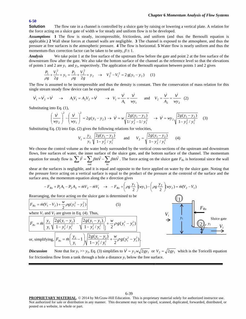
Chapter 6 Momentum Analysis of Flow Systems
PROPRIETARY MATERIAL. © 2014 by McGraw-Hill Education. This is proprietary material solely for authorized instructor use. Not authorized for sale or distribution in any manner. This document may not be copied, scanned, duplicated, forwarded, distributed, or posted on a website, in whole or part.
6-39
6-50 Solution The flow rate in a channel is controlled by a sluice gate by raising or lowering a vertical plate. A relation for the force acting on a sluice gate of width w for steady and uniform flow is to be developed. Assumptions 1 The flow is steady, incompressible, frictionless, and uniform (and thus the Bernoulli equation is applicable.) 2 Wall shear forces at channel walls are negligible. 3 The channel is exposed to the atmosphere, and thus the pressure at free surfaces is the atmospheric pressure. 4 The flow is horizontal. 5 Water flow is nearly uniform and thus the momentum-flux correction factor can be taken to be unity, 1. Analysis We take point 1 at the free surface of the upstream flow before the gate and point 2 at the free surface of the downstream flow after the gate. We also take the bottom surface of the channel as the reference level so that the elevations of points 1 and 2 are y1 and y2, respectively. The application of the Bernoulli equation between points 1 and 2 gives
)g( 2 22 21
21
222
222
1
211 yyVVy
g
V
g
Py
g
V
g
P
(1)
The flow is assumed to be incompressible and thus the density is constant. Then the conservation of mass relation for this single stream steady flow device can be expressed as
and 22
211
1221121 wyAV
wyAVVAVA
VVVVVVVV
(2)
Substituting into Eq. (1),
21
22
2122
122
2121
2
1
2
2 /1
)(2
/1/1
)(2 )(2
yy
yygwy
yy
yygwyyg
wywy
VV
VV
(3)
Substituting Eq. (3) into Eqs. (2) gives the following relations for velocities,
/1
)(2and
/1
)(221
22
2122
122
21
1
21
yy
yygV
yy
yyg
y
yV
(4)
We choose the control volume as the water body surrounded by the vertical cross-sections of the upstream and downstream flows, free surfaces of water, the inner surface of the sluice gate, and the bottom surface of the channel. The momentum
equation for steady flow is inout
VmVmF
. The force acting on the sluice gate FRx is horizontal since the wall
shear at the surfaces is negligible, and it is equal and opposite to the force applied on water by the sluice gate. Noting that the pressure force acting on a vertical surface is equal to the product of the pressure at the centroid of the surface and the surface area, the momentum equation along the x direction gives
)()(2
)(2
1222
11
122211 VVmwyy
gwyy
gFVmVmAPAPF RxRx
Rearranging, the force acting on the sluice gate is determined to be
)(2
)( 22
2121 yyg
wVVmFRx (5)
where V1 and V2 are given in Eq. (4). Thus,
2 22 1 2 1 21 22 2 2 2
1 2 1 2 1
2 ( ) 2 ( )( )
1 / 1 / 2Rx
y g y y g y y wF m g y y
y y y y y
or, simplifying, 2 22 1 21 22 2
1 2 1
2 ( )1 ( )
1 / 2Rx
y g y y wF m g y y
y y y
.
Discussion Note that for y1 >> y2, Eq. (3) simplifies to 12 2gywyV or 12 2gyV which is the Toricelli equation
for frictionless flow from a tank through a hole a distance y1 below the free surface.
Sluice gate y1
y2
V1
V2
1
2
FRx

Chapter 6 Momentum Analysis of Flow Systems
PROPRIETARY MATERIAL. © 2014 by McGraw-Hill Education. This is proprietary material solely for authorized instructor use. Not authorized for sale or distribution in any manner. This document may not be copied, scanned, duplicated, forwarded, distributed, or posted on a website, in whole or part.
6-40
Angular Momentum Equation
6-51C
Solution We are to discuss how the angular momentum equation is obtained from the RTT.
Analysis The angular momentum equation is obtained by replacing B in the Reynolds transport theorem by the
total angular momentum sysH
, and b by the angular momentum per unit mass Vr
.
Discussion The RTT is a general equation that holds for any property B, either scalar or (as in this case) vector.
6-52C
Solution We are to express the angular momentum equation in scalar form about a specified axis.
Analysis The angular momentum equation about a given fixed axis in this case can be expressed in scalar form as
inout
VmrVmrM where r is the moment arm, V is the magnitude of the radial velocity, and m is the mass
flow rate.
Discussion This is a simplification of the more general angular momentum equation (many terms have dropped out).
6-53C
Solution We are to express the angular momentum equation for a specific (restricted) control volume.
Analysis The angular momentum equation in this case is expressed as VmrI
where
is the angular
acceleration of the control volume, and r
is the vector from the axis of rotation to any point on the line of action of F
.
Discussion This is a simplification of the more general angular momentum equation (many terms have dropped out).
6-54C
Solution We are to compare the angular momentum of two rotating bodies
Analysis No. The two bodies do not necessarily have the same angular momentum. Two rigid bodies having the same mass and angular speed may have different angular momentums unless they also have the same moment of inertia I.
Discussion The reason why flywheels have most of their mass at the outermost radius, is to maximize the angular momentum.

Chapter 6 Momentum Analysis of Flow Systems
PROPRIETARY MATERIAL. © 2014 by McGraw-Hill Education. This is proprietary material solely for authorized instructor use. Not authorized for sale or distribution in any manner. This document may not be copied, scanned, duplicated, forwarded, distributed, or posted on a website, in whole or part.
6-41
6-55
Solution Water is pumped through a piping section. The moment acting on the elbow for the cases of downward and upward discharge is to be determined.
Assumptions 1 The flow is steady and incompressible. 2 The water is discharged to the atmosphere, and thus the gage pressure at the outlet is zero. 3 Effects of water falling down during upward discharge is disregarded. 4 Pipe outlet diameter is small compared to the moment arm, and thus we use average values of radius and velocity at the outlet.
Properties We take the density of water to be 1000 kg/m3.
Analysis We take the entire pipe as the control volume, and designate the inlet by 1 and the outlet by 2. We also take the x and y coordinates as shown. The control volume and the reference frame are fixed. The conservation of mass equation for this one-inlet one-outlet steady flow system is mmm 21 , and
VVV 21 since Ac = constant. The mass flow rate and the weight of the
horizontal section of the pipe are
kg/s 7.123)m/s 7](4/m) 15.0()[kg/m (1000 23 VAm c
N/m 3.294m/skg 1
N 1)m/s 81.9)(m 2)(kg/m (15
22
mgW
(a) Downward discharge: To determine the moment acting on the pipe at point A, we need to take the moment of all forces and momentum flows about that point. This is a steady and uniform flow problem, and all forces and momentum flows are in the same plane. Therefore, the angular momentum equation in this case can be expressed as
inout
VmrVmrM where r is the moment arm, all moments in the counterclockwise direction are positive, and all
in the clockwise direction are negative.
The free body diagram of the pipe section is given in the figure. Noting that the moments of all forces and momentum flows passing through point A are zero, the only force that will yield a moment about point A is the weight W of the horizontal pipe section, and the only momentum flow that will yield a moment is the outlet stream (both are negative since both moments are in the clockwise direction). Then the angular momentum equation about point A becomes
221 VmrWrM A
Solving for MA and substituting,
mN 1438
2221m/skg 1
N 1m/s) kg/s)(7 m)(123.7 (2N) m)(294.3 1(VmrWrM A
The negative sign indicates that the assumed direction for MA is wrong, and should be reversed. Therefore, a moment of 70 Nm acts at the stem of the pipe in the clockwise direction.
(b) Upward discharge: The moment due to discharge stream is positive in this case, and the moment acting on the pipe at point A is
mN 2026
2221m/skg 1
N 1m/s) kg/s)(7 m)(123.7 (2N) m)(294.3 1(VmrWrM A
Discussion Note direction of discharge can make a big difference in the moments applied on a piping system. This problem also shows the importance of accounting for the moments of momentums of flow streams when performing evaluating the stresses in pipe materials at critical cross-sections.
2Vm
W
A
MA
1Vm
r1 = 1 m r2 = 2 m
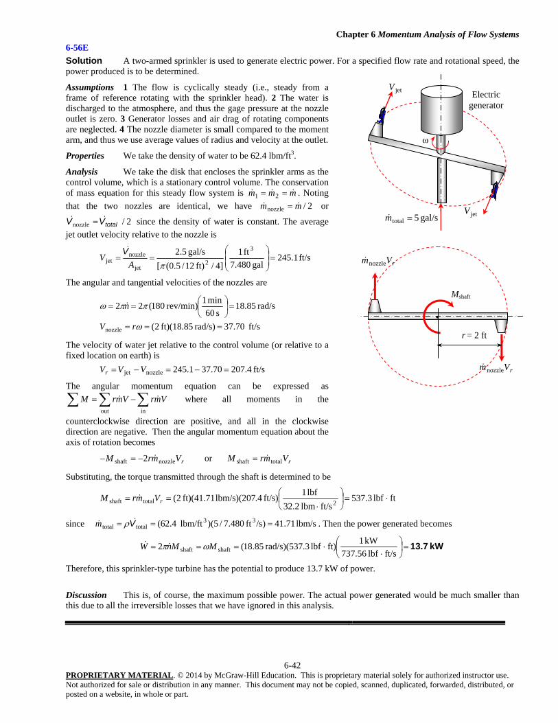
Chapter 6 Momentum Analysis of Flow Systems
PROPRIETARY MATERIAL. © 2014 by McGraw-Hill Education. This is proprietary material solely for authorized instructor use. Not authorized for sale or distribution in any manner. This document may not be copied, scanned, duplicated, forwarded, distributed, or posted on a website, in whole or part.
6-42
6-56E
Solution A two-armed sprinkler is used to generate electric power. For a specified flow rate and rotational speed, the power produced is to be determined.
Assumptions 1 The flow is cyclically steady (i.e., steady from a frame of reference rotating with the sprinkler head). 2 The water is discharged to the atmosphere, and thus the gage pressure at the nozzle outlet is zero. 3 Generator losses and air drag of rotating components are neglected. 4 The nozzle diameter is small compared to the moment arm, and thus we use average values of radius and velocity at the outlet.
Properties We take the density of water to be 62.4 lbm/ft3.
Analysis We take the disk that encloses the sprinkler arms as the control volume, which is a stationary control volume. The conservation of mass equation for this steady flow system is mmm 21 . Noting
that the two nozzles are identical, we have 2/nozzle mm or
2/nozzle totalVV since the density of water is constant. The average
jet outlet velocity relative to the nozzle is
ft/s 1.245gal 480.7
ft 1
]4/ft) 12/5.0([
gal/s 5.2 3
2jet
nozzlejet
A
VV
The angular and tangential velocities of the nozzles are
ft/s .7037rad/s) ft)(18.85 2(
rad/s .8518s 60
min 1rev/min) 180(22
nozzle
rV
n
The velocity of water jet relative to the control volume (or relative to a fixed location on earth) is
ft/s 4.20770.371.245nozzlejet VVVr
The angular momentum equation can be expressed as
inout
VmrVmrM where all moments in the
counterclockwise direction are positive, and all in the clockwise direction are negative. Then the angular momentum equation about the axis of rotation becomes
rVmrM nozzleshaft 2 or rVmrM totalshaft
Substituting, the torque transmitted through the shaft is determined to be
ftlbf 3.537ft/slbm 32.2
lbf 1ft/s) .4lbm/s)(207 ft)(41.71 2(
2totalshaft
rVmrM
since lbm/s 71.41)/sft 480.7/5)(lbm/ft (62.4 33totaltotal V m . Then the power generated becomes
kW 13.7
ft/slbf 737.56
kW 1ft)lbf .3rad/s)(537 85.18(2 shaftshaft MMnW
Therefore, this sprinkler-type turbine has the potential to produce 13.7 kW of power.
Discussion This is, of course, the maximum possible power. The actual power generated would be much smaller than this due to all the irreversible losses that we have ignored in this analysis.
rVmnozzle
rVmnozzle
Mshaft
r = 2 ft
gal/s 5total m
Electric generator
jetV
jetV

Chapter 6 Momentum Analysis of Flow Systems
PROPRIETARY MATERIAL. © 2014 by McGraw-Hill Education. This is proprietary material solely for authorized instructor use. Not authorized for sale or distribution in any manner. This document may not be copied, scanned, duplicated, forwarded, distributed, or posted on a website, in whole or part.
6-43
6-57E
Solution A two-armed sprinkler is used to generate electric power. For a specified flow rate and rotational speed, the moment acting on the rotating head when the head is stuck is to be determined.
Assumptions 1 The flow is uniform and steady. 2 The water is discharged to the atmosphere, and thus the gage pressure at the nozzle outlet is zero. 3 The nozzle diameter is small compared to the moment arm, and thus we use average values of radius and velocity at the outlet.
Properties We take the density of water to be 62.4 lbm/ft3.
Analysis We take the disk that encloses the sprinkler arms as the control volume, which is a stationary control volume. The conservation of mass equation for this steady flow system is mmm 21 . Noting that the two nozzles are
identical, we have 2/nozzle mm or nozzle total 2/V V since the density of water is constant. The average jet outlet velocity
relative to the nozzle is
ft/s 1.245gal 480.7
ft 1
]4/ft) 12/5.0([
gal/s 5.2 3
2jet
nozzlejet
A
VV
The angular momentum equation can be expressed as inout
VmrVmrM where all moments in the
counterclockwise direction are positive, and all in the clockwise direction are negative. Then the angular momentum equation about the axis of rotation becomes
jetVmrM nozzleshaft 2 or jetVmrM totalshaft
Substituting, the torque transmitted through the shaft is determined to be
ftlbf 635
2totalshaft
ft/slbm 32.2
lbf 1ft/s) .1lbm/s)(245 ft)(41.71 2(jetVmrM
since lbm/s 71.41)/sft 480.7/5)(lbm/ft (62.4 33totaltotal V m .
Discussion When the sprinkler is stuck and thus the angular velocity is zero, the torque developed is maximum since 0nozzle V and thus ft/s 1.245jetr VV , giving Mshaft,max = 635 lbfft. But the power generated is zero in this case since
the shaft does not rotate.
rVmnozzle
rVmnozzle
Mshaft
r = 2 ft
gal/s 5total m
Electric generator
jetV
jetV
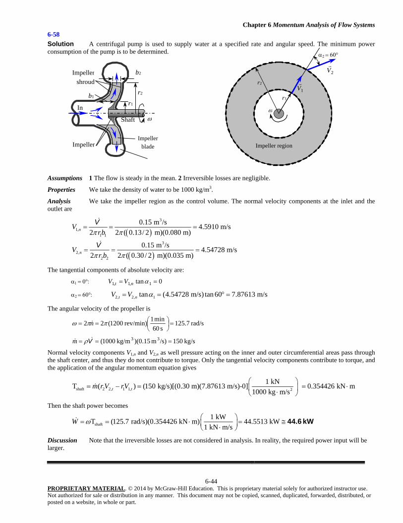
Chapter 6 Momentum Analysis of Flow Systems
PROPRIETARY MATERIAL. © 2014 by McGraw-Hill Education. This is proprietary material solely for authorized instructor use. Not authorized for sale or distribution in any manner. This document may not be copied, scanned, duplicated, forwarded, distributed, or posted on a website, in whole or part.
6-44
6-58
Solution A centrifugal pump is used to supply water at a specified rate and angular speed. The minimum power consumption of the pump is to be determined.
Assumptions 1 The flow is steady in the mean. 2 Irreversible losses are negligible.
Properties We take the density of water to be 1000 kg/m3.
Analysis We take the impeller region as the control volume. The normal velocity components at the inlet and the outlet are
3
1,1 1
3
2,2 2
0.15 m /s4.5910 m/s
2 2 ( 0.13/ 2 m)(0.080 m)
0.15 m /s4.54728 m/s
2 2 ( 0.30 / 2 m)(0.035 m)
n
n
Vrb
Vr b
V
V
The tangential components of absolute velocity are:
0tan 1,1,1 nt VV
2, 2, 1tan (4.54728 m/s) tan 60 7.87613 m/st nV V
The angular velocity of the propeller is
rad/s7.125s 60
min 1 rev/min)1200(22
n
kg/s150/s)m )(0.15 kg/m1000( 33 V m
Normal velocity components V1,n and V2,n as well pressure acting on the inner and outer circumferential areas pass through the shaft center, and thus they do not contribute to torque. Only the tangential velocity components contribute to torque, and the application of the angular momentum equation gives
shaft 2 2, 1 1, 2
1 kNT ( ) (150 kg/s)[(0.30 m)(7.87613 m/s)-0] 0.354426 kN m
1000 kg m/st tm r V rV
Then the shaft power becomes
shaft
1 kWT (125.7 rad/s)(0.354426 kN m) 44.5513 kW
1 kN m/sW 44.6 kW
Discussion Note that the irreversible losses are not considered in analysis. In reality, the required power input will be larger.
In
Impeller
blade
Shaft
r1
b2
b1 r2
Impeller
shroud
Impeller
r 1
r2
2V
Impeller region
1V

Chapter 6 Momentum Analysis of Flow Systems
PROPRIETARY MATERIAL. © 2014 by McGraw-Hill Education. This is proprietary material solely for authorized instructor use. Not authorized for sale or distribution in any manner. This document may not be copied, scanned, duplicated, forwarded, distributed, or posted on a website, in whole or part.
6-45
6-59
Solution A centrifugal blower is used to deliver atmospheric air. For a given angular speed and power input, the volume flow rate of air is to be determined.
Assumptions 1 The flow is steady in the mean. 2 Irreversible losses are negligible. 3 The tangential components of air velocity at the inlet and the outlet are said to be equal to the impeller velocity at respective locations.
Properties The gas constant of air is 0.287 kPam3/kgK. The density of air at 20C and 95 kPa is
33
kg/m 1.130K) K)(293/kgmkPa (0.287
kPa 95
RT
P
Analysis In the idealized case of the tangential fluid velocity being equal to the blade angular velocity both at the inlet and the outlet, we have 1,1 rV t and 2,2 rV t , and the torque is expressed as
)()()(T 21
22
21
22,11,22shaft rrrrmVrVrm tt V
where the angular velocity is
rad/s 25.94s 60
min 1rev/min) 900(22
n
Then the shaft power becomes
)(T 21
22
2shaftshaft rrW V
Solving for V and substituting, the volume flow rate of air is determined to
/sm 0.2075 3
N 1
m/skg 1
]m) (0.18m) [(0.30rad/s) )(94.25kg/m (1.130
m/sN 120
)(
2
222321
22
2shaft
rr
W
V
The normal velocity components at the inlet and the outlet are
m/s 3.24
m/s 3.01
m) m)(0.034 30.0(2
/sm 2075.0
2
m) m)(0.061 18.0(2
/sm 2075.0
23
22,2
3
11,1
brV
brV
n
n
V
V
Discussion Note that the irreversible losses are not considered in this analysis. In reality, the flow rate and the normal components of velocities will be smaller.
r 1
r2
tV ,2
tV ,1
In
Impeller
blade
Shaft
r1
b2
b1 r2
Impeller
shroud
Impeller

Chapter 6 Momentum Analysis of Flow Systems
PROPRIETARY MATERIAL. © 2014 by McGraw-Hill Education. This is proprietary material solely for authorized instructor use. Not authorized for sale or distribution in any manner. This document may not be copied, scanned, duplicated, forwarded, distributed, or posted on a website, in whole or part.
6-46
6-60
Solution Water enters a two-armed sprinkler vertically, and leaves the nozzles horizontally. For a specified flow rate, the rate of rotation of the sprinkler and the torque required to prevent the sprinkler from rotating are to be determined. Assumptions 1The flow is uniform and cyclically steady (i.e., steady from a frame of reference rotating with the sprinkler head). 2 The water is discharged to the atmosphere, and thus the gage pressure at the nozzle outlet is zero. 3 Frictional effects and air drag of rotating components are neglected. 4 The nozzle diameter is small compared to the moment arm, and thus we use average values of radius and velocity at the outlet. Properties We take the density of water to be 1000 kg/m3 = 1 kg/L. Analysis We take the disk that encloses the sprinkler arms as the control volume, which is a stationary control volume. The conservation of mass equation for this symmetrical steady flow system is
mmm 21 or total2 jet,1 jet, VVV since the
density of water is constant. Both jets are at the same elevation and pressure, and the frictional effects are said to be negligible. Also, the head losses in each arm are equal, so that mass flow rates in each nozzle are identical. Then,
m/s 33.58L 1000
m 1
m 103
L/s 5/2)3(23
241 jet,
total
1, jet,
AV r
V
m/s 00.35L 1000
m 1
m 105
L/s 5/2)3(23
242 jet,
total
2, jet,
AV r
V
Noting that rnrV 2nozzle and assuming the sprinkler to rotate in the clock-wise direction, the absolute water jet
speeds in the tangential direction can be expressed as
11, jet,1 nozzle,1, jet,1 jet, rVVVV rr (Nozzle and water jet move in the same direction).
22, jet,2 nozzle,2, jet,2 jet, rVVVV rr (Nozzle and water jet move in opposite directions).
The angular momentum equation about the axis of rotation can be expressed as inout
VmrVmrM where r is the
average moment arm, V is the average absolute speed (relative to an inertial reference frame), all moments in the counterclockwise direction are positive, and all moments in the clockwise direction are negative. Momentum flows in the clockwise direction are also negative. Then the angular momentum equation becomes
2 jet,jet,221 jet,jet,11shaftT VmrVmr )()(T 22, jet,jet,2211, jet,jet,11shaft rVmrrVmr rr
Noting that rAVm jet,jet and rearranging,
2,1, kg/s 5.171000/5.171000 jetjet mVm
(a) In the case of free spin with no frictional effects, we have Tshaft = 0 and thus )()(0 22
212
1 jet,1122 ArArVArAr r .
Then angular speed and the rate of rotation of sprinkler head becomes )35.035(5.1735.0)5.033.58(5.175.00
ockwise)(countercl rad/s 41.45 rpm 434
(b) When the sprinkler is prevented from rotating, we have = 0. Then the required torque becomes
mN 296 355.1735.033.585.175.0T 2, jet,jet,221, jet,jet,11shaft rr VmrVmr
Discussion The rate of rotation determined in (a) will be lower in reality because of frictional effects and air drag.
r1= 50 cm r2= 35 cm
Water jet
jet
Water jet
jet
Vjet, 1 A1
Vjet, 2 A2
1 2
A
Tshaft

Chapter 6 Momentum Analysis of Flow Systems
PROPRIETARY MATERIAL. © 2014 by McGraw-Hill Education. This is proprietary material solely for authorized instructor use. Not authorized for sale or distribution in any manner. This document may not be copied, scanned, duplicated, forwarded, distributed, or posted on a website, in whole or part.
6-47
6-61 Solution Water enters a two-armed sprinkler vertically, and leaves the nozzles horizontally. For a specified flow rate, the rate of rotation of the sprinkler and the torque required to prevent the sprinkler from rotating are to be determined. Assumptions 1The flow is uniform and cyclically steady (i.e., steady from a frame of reference rotating with the sprinkler head). 2 The water is discharged to the atmosphere, and thus the gage pressure at the nozzle outlet is zero. 3 Frictional effects and air drag of rotating components are neglected. 4 The nozzle diameter is small compared to the moment arm, and thus we use average values of radius and velocity at the outlet. Properties We take the density of water to be 1000 kg/m3 = 1 kg/L. Analysis We take the disk that encloses the sprinkler arms as the control volume, which is a stationary control volume. The conservation of mass equation for this symmetrical steady flow system is
mmm 21 or total2 jet,1 jet, VVV since the
density of water is constant. Both jets are at the same elevation and pressure, and the frictional effects are said to be negligible. Also, the head losses in each arm are equal, so that mass flow rates in each nozzle are identical. Then,
m/s 33.83L 1000
m 1
m 103
L/s )2/50(23
241 jet,
total
1, jet,
AV r
V
m/s 0.50L 1000
m 1
m 105
L/s )2/50(23
242 jet,
total
2, jet,
AV r
V
Noting that rnrV 2nozzle and assuming the sprinkler to rotate in the clock-wise direction, the absolute water jet
speeds in the tangential direction can be expressed as
11, jet,1 nozzle,1, jet,1 jet, rVVVV rr (Nozzle and water jet move in the same direction).
22, jet,2 nozzle,2, jet,2 jet, rVVVV rr (Nozzle and water jet move in opposite directions).
The angular momentum equation about the axis of rotation can be expressed as inout
VmrVmrM where r is the
average moment arm, V is the average absolute speed (relative to an inertial reference frame), all moments in the counterclockwise direction are positive, and all moments in the clockwise direction are negative. Momentum flows in the clockwise direction are also negative. Then the angular momentum equation becomes
2 jet,jet,221 jet,jet,11shaftT VmrVmr )()(T 22, jet,jet,2211, jet,jet,11shaft rVmrrVmr rr
Noting that rAVm jet,jet and rearranging,
2,1, kg/s 251000/251000 jetjet mVm
(a) In the case of free spin with no frictional effects, we have Tshaft = 0 and thus )()(0 22
212
1 jet,1122 ArArVArAr r .
Then angular speed and the rate of rotation of sprinkler head becomes )35.050(2535.0)5.033.83(255.00
ockwise)(countercl rad/s 89.64 rpm 620
(b) When the sprinkler is prevented from rotating, we have = 0. Then the required torque becomes
mN 604 502535.033.83255.0T 2, jet,jet,221, jet,jet,11shaft rr VmrVmr
Discussion The rate of rotation determined in (a) will be lower in reality because of frictional effects and air drag.
r1= 50 cm r2= 35 cm
Water jet
jet
Water jet
jet
Vjet, 1 A1
Vjet, 2 A2
1 2
A
Tshaft

Chapter 6 Momentum Analysis of Flow Systems
PROPRIETARY MATERIAL. © 2014 by McGraw-Hill Education. This is proprietary material solely for authorized instructor use. Not authorized for sale or distribution in any manner. This document may not be copied, scanned, duplicated, forwarded, distributed, or posted on a website, in whole or part.
6-48
6-62
Solution A centrifugal blower is used to deliver atmospheric air at a specified rate and angular speed. The minimum power consumption of the blower is to be determined.
Assumptions 1 The flow is steady in the mean. 2 Irreversible losses are negligible.
Properties The density of air is given to be 1.25 kg/m3.
Analysis We take the impeller region as the control volume. The normal velocity components at the inlet and the outlet are
m/s 4.421m) m)(0.056 45.0(2
/sm 70.0
2
m/s 6.793m) m)(0.082 20.0(2
/sm 70.0
23
22,2
3
11,1
brV
brV
n
n
V
V
The tangential components of absolute velocity are:
0tan 1,1,1 nt VV
m/s 269.550tan)m/s 421.4(tan 1,2,2 nt VV
The angular velocity of the propeller is
rad/s30.73s 60
min 1 rev/min)700(22
n
kg/s875.0/s)m )(0.7 kg/m25.1( 33 V m
Normal velocity components V1,n and V2,n as well pressure acting on the inner and outer circumferential areas pass through the shaft center, and thus they do not contribute to torque. Only the tangential velocity components contribute to torque, and the application of the angular momentum equation gives
mN 075.2 m/s kg1
N 10]-m/s) m)(5.269 45 kg/s)[(0.875.0()(T
2,11,22shaft
tt VrVrm
Then the shaft power becomes
W152
m/sN 1
W 1m)N 075 rad/s)(2.30.73(TshaftW
Discussion The actual required shaft power is greater than this, due to the friction and other irreversibilities that we have neglected in our analysis. Nevertheless, this is a good first approximation.
In
Impeller
blade
Shaft
r1
b2
b1 r2
Impeller
shroud
Impeller
r 1
r2
Impeller region
1V
2V
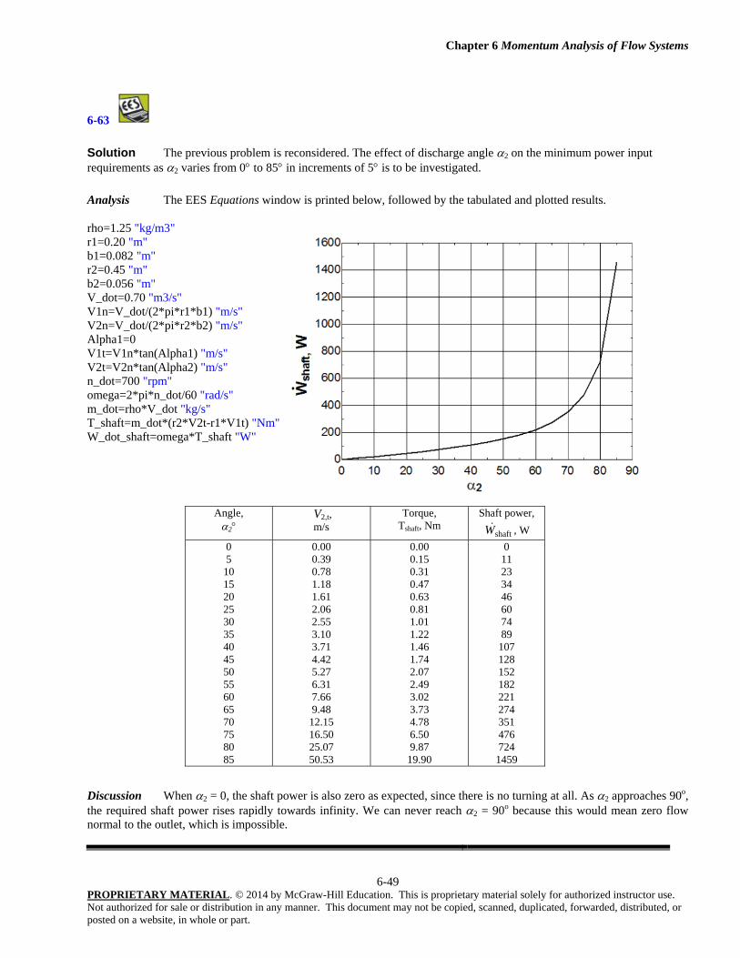
Chapter 6 Momentum Analysis of Flow Systems
PROPRIETARY MATERIAL. © 2014 by McGraw-Hill Education. This is proprietary material solely for authorized instructor use. Not authorized for sale or distribution in any manner. This document may not be copied, scanned, duplicated, forwarded, distributed, or posted on a website, in whole or part.
6-49
6-63
Solution The previous problem is reconsidered. The effect of discharge angle 2 on the minimum power input requirements as 2 varies from 0 to 85 in increments of 5 is to be investigated.
Analysis The EES Equations window is printed below, followed by the tabulated and plotted results.
rho=1.25 "kg/m3" r1=0.20 "m" b1=0.082 "m" r2=0.45 "m" b2=0.056 "m" V_dot=0.70 "m3/s" V1n=V_dot/(2*pi*r1*b1) "m/s" V2n=V_dot/(2*pi*r2*b2) "m/s" Alpha1=0 V1t=V1n*tan(Alpha1) "m/s" V2t=V2n*tan(Alpha2) "m/s" n_dot=700 "rpm" omega=2*pi*n_dot/60 "rad/s" m_dot=rho*V_dot "kg/s" T_shaft=m_dot*(r2*V2t-r1*V1t) "Nm" W_dot_shaft=omega*T_shaft "W"
Angle, 2
V2,t, m/s
Torque, Tshaft, Nm
Shaft power,
shaftW , W
0 5 10 15 20 25 30 35 40 45 50 55 60 65 70 75 80 85
0.00 0.39 0.78 1.18 1.61 2.06 2.55 3.10 3.71 4.42 5.27 6.31 7.66 9.48
12.15 16.50 25.07 50.53
0.00 0.15 0.31 0.47 0.63 0.81 1.01 1.22 1.46 1.74 2.07 2.49 3.02 3.73 4.78 6.50 9.87
19.90
0 11 23 34 46 60 74 89
107 128 152 182 221 274 351 476 724 1459
Discussion When 2 = 0, the shaft power is also zero as expected, since there is no turning at all. As 2 approaches 90o, the required shaft power rises rapidly towards infinity. We can never reach 2 = 90o because this would mean zero flow normal to the outlet, which is impossible.
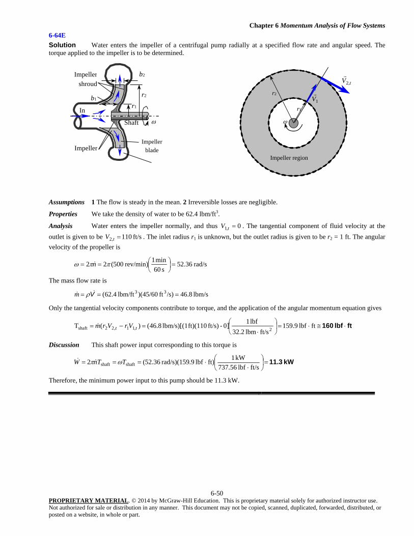
Chapter 6 Momentum Analysis of Flow Systems
PROPRIETARY MATERIAL. © 2014 by McGraw-Hill Education. This is proprietary material solely for authorized instructor use. Not authorized for sale or distribution in any manner. This document may not be copied, scanned, duplicated, forwarded, distributed, or posted on a website, in whole or part.
6-50
6-64E
Solution Water enters the impeller of a centrifugal pump radially at a specified flow rate and angular speed. The torque applied to the impeller is to be determined.
Assumptions 1 The flow is steady in the mean. 2 Irreversible losses are negligible.
Properties We take the density of water to be 62.4 lbm/ft3.
Analysis Water enters the impeller normally, and thus 0,1 tV . The tangential component of fluid velocity at the
outlet is given to be ft/s 110,2 tV . The inlet radius r1 is unknown, but the outlet radius is given to be r2 = 1 ft. The angular
velocity of the propeller is
rad/s36.52s 60
min 1 rev/min)500(22
n
The mass flow rate is
lbm/s 8.46/s)ft )(45/60lbm/ft 4.62( 33 V m
Only the tangential velocity components contribute to torque, and the application of the angular momentum equation gives
ftlbf 160
ftlbf 9.159ft/slbm 32.2
lbf 10] - ft/s) ft)(110 lbm/s)[(1 8.46()(T
2,11,22shaft tt VrVrm
Discussion This shaft power input corresponding to this torque is
kW 11.3
ft/slbf 737.56
kW 1ft)lbf .9rad/s)(159 36.52(2 shaftshaft TTnW
Therefore, the minimum power input to this pump should be 11.3 kW.
In
Impeller
blade
Shaft
r1
b2
b1 r2
Impeller
shroud
Impeller
r 1
r2
tV ,2
Impeller region
1V

Chapter 6 Momentum Analysis of Flow Systems
PROPRIETARY MATERIAL. © 2014 by McGraw-Hill Education. This is proprietary material solely for authorized instructor use. Not authorized for sale or distribution in any manner. This document may not be copied, scanned, duplicated, forwarded, distributed, or posted on a website, in whole or part.
6-51
6-65
Solution A three-armed sprinkler is used to water a garden. For a specified flow rate and resistance torque, the angular velocity of the sprinkler head is to be determined.
Assumptions 1 The flow is uniform and cyclically steady (i.e., steady from a frame of reference rotating with the sprinkler head). 2 The water is discharged to the atmosphere, and thus the gage pressure at the nozzle outlet is zero. 3 Air drag of rotating components are neglected. 4 The nozzle diameter is small compared to the moment arm, and thus we use average values of radius and velocity at the outlet.
Properties We take the density of water to be 1000 kg/m3 = 1 kg/L.
Analysis We take the disk that encloses the sprinkler arms as the control volume, which is a stationary control volume. The conservation of mass equation for this steady flow system is mmm 21 . Noting
that the three nozzles are identical, we have 3/nozzle mm or
3/nozzle totalVV since the density of water is constant. The average jet
outlet velocity relative to the nozzle and the mass flow rate are
m/s 113.2L 1000
m 1
]4/m) 015.0([3
L/s 60 3
2jet
nozzlejet
AV
V
kg/s 60)L/s 60)(kg/L (1totaltotal V m
The angular momentum equation can be expressed as
inout
VmrVmrM
where all moments in the counterclockwise direction are positive, and all in the clockwise direction are negative. Then the angular momentum equation about the axis of rotation becomes
rVmr nozzle0 3T or rVmr total0T
Solving for the relative velocity Vr and substituting,
m/s 08.2N 1
m/skg 1
kg/s) m)(60 40.0(
mN 50T 2
total
0
mrVr
Then the tangential and angular velocity of the nozzles become
m/s 1.11108.22.113jetnozzle rVVV
rpm 2650
rad/s 278
rpm 2652min 1
s 60
2
rad/s 278
2
m 4.0
m/s 1.111nozzle
n
r
V
Therefore, this sprinkler will rotate at 2650 revolutions per minute (to three significant digits).
Discussion The actual rotation rate will be somewhat lower than this due to air friction as the arms rotate.
L/s 60total V
Electric generator
jetV
jetV
rVmnozzlerVmnozzle
r = 40 cm
rVmnozzle
To = 50 Nm

Chapter 6 Momentum Analysis of Flow Systems
PROPRIETARY MATERIAL. © 2014 by McGraw-Hill Education. This is proprietary material solely for authorized instructor use. Not authorized for sale or distribution in any manner. This document may not be copied, scanned, duplicated, forwarded, distributed, or posted on a website, in whole or part.
6-52
6-66
Solution A Pelton wheel is considered for power generation in a hydroelectric power plant. A relation is to be obtained for power generation, and its numerical value is to be obtained.
Assumptions 1 The flow is uniform and cyclically steady. 2 The water is discharged to the atmosphere, and thus the gage pressure at the nozzle outlet is zero. 3 Friction and losses due to air drag of rotating components are neglected. 4 The nozzle diameter is small compared to the moment arm, and thus we use average values of radius and velocity at the outlet.
Properties We take the density of water to be 1000 kg/m3 = 1 kg/L.
Analysis The tangential velocity of buckets corresponding to an angular velocity of n 2 is rV bucket . Then
the relative velocity of the jet (relative to the bucket) becomes
rVVVV jjr bucket
We take the imaginary disk that contains the Pelton wheel as the control volume. The inlet velocity of the fluid into this control volume is Vr, and the component of outlet velocity normal to the moment arm is Vrcos. The angular momentum
equation can be expressed as inout
VmrVmrM where all moments in the counterclockwise direction are
positive, and all in the clockwise direction are negative. Then the angular momentum equation about the axis of rotation becomes
rr VmrVmrM cosshaft or )cos1)(()cos1(shaft rVmrVmrM jr
Noting that shaftshaftshaft 2 MMnW and V m , the shaft power output of a Pelton turbine becomes
)cos1)((shaft rVrW jV
which is the desired relation. For given values, the shaft power output is determined to be
MW 11.3
m/sN 10
MW 1)cos160-m/s)(1 15.712- rad/s)(5071.15(m) 2)(/sm 10)( kg/m1000(
633
shaftW
where rad/s71.15s 60
min 1 rev/min)150(22
n
Discussion The actual power will be somewhat lower than this due to air drag and friction. Note that this is the shaft power; the electrical power generated by the generator connected to the shaft is be lower due to generator inefficiencies.
Vj - r
Vj - r
Shaft
r
Nozzle
r Vj
Mshaft
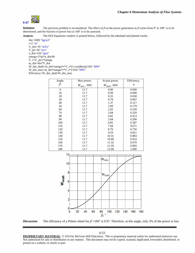
Chapter 6 Momentum Analysis of Flow Systems
PROPRIETARY MATERIAL. © 2014 by McGraw-Hill Education. This is proprietary material solely for authorized instructor use. Not authorized for sale or distribution in any manner. This document may not be copied, scanned, duplicated, forwarded, distributed, or posted on a website, in whole or part.
6-53
6-67
Solution The previous problem is reconsidered. The effect of on the power generation as varies from 0 to 180 is to be determined, and the fraction of power loss at 160 is to be assessed.
Analysis The EES Equations window is printed below, followed by the tabulated and plotted results.
rho=1000 "kg/m3" r=2 "m" V_dot=10 "m3/s" V_jet=50 "m/s" n_dot=150 "rpm" omega=2*pi*n_dot/60 V_r=V_jet-r*omega m_dot=rho*V_dot W_dot_shaft=m_dot*omega*r*V_r*(1-cos(Beta))/1E6 "MW" W_dot_max=m_dot*omega*r*V_r*2/1E6 "MW" Efficiency=W_dot_shaft/W_dot_max
Angle,
Max power,
maxW , MW
Actual power,
shaftW , MW
Efficiency,
0 10 20 30 40 50 60 70 80 90
100 110 120 130 140 150 160 170 180
11.7 11.7 11.7 11.7 11.7 11.7 11.7 11.7 11.7 11.7 11.7 11.7 11.7 11.7 11.7 11.7 11.7 11.7 11.7
0.00 0.09 0.35 0.78 1.37 2.09 2.92 3.84 4.82 5.84 6.85 7.84 8.76 9.59
10.31 10.89 11.32 11.59 11.68
0.000 0.008 0.030 0.067 0.117 0.179 0.250 0.329 0.413 0.500 0.587 0.671 0.750 0.821 0.883 0.933 0.970 0.992 1.000
Discussion The efficiency of a Pelton wheel for =160 is 0.97. Therefore, at this angle, only 3% of the power is lost.

Chapter 6 Momentum Analysis of Flow Systems
PROPRIETARY MATERIAL. © 2014 by McGraw-Hill Education. This is proprietary material solely for authorized instructor use. Not authorized for sale or distribution in any manner. This document may not be copied, scanned, duplicated, forwarded, distributed, or posted on a website, in whole or part.
6-54
Review Problems
6-68
Solution Water is deflected by an elbow. The force acting on the flanges of the elbow and the angle its line of action makes with the horizontal are to be determined.
Assumptions 1 The flow is steady and incompressible. 2 Frictional effects are negligible (so that the Bernoulli equation can be used). 3 The water is discharged to the atmosphere, and thus the gage pressure at the outlet is zero.
Properties We take the density of water to be 1000 kg/m3.
Analysis
Writing Bernoulli equation between 1 (elbow entrance)-2 (exit) ;
lossesnegligiblezVPzVP 22
2212
11 2
1
2
1
smV /26.2
43.0
16.021
, smV /37.202 , z1=0.5m , z2=0m ,P2=0
5.0981026.237.2010002
1
2
1 221
21
221 zVVP
kPaPaP 200200101
Linear momentum equation for the CV gives;
x
cscv
FdAnVVdVt
V
x component
xRAPAVVAVV 11222111 cos
xRAPQVQV 112
22
1 cos
xRAPVVQ 112
22
1 )cos(
xR4
3.020001060cos37.2026.216.01000
222

Chapter 6 Momentum Analysis of Flow Systems
PROPRIETARY MATERIAL. © 2014 by McGraw-Hill Education. This is proprietary material solely for authorized instructor use. Not authorized for sale or distribution in any manner. This document may not be copied, scanned, duplicated, forwarded, distributed, or posted on a website, in whole or part.
6-55
)(48150 leftNRx
y component
ycvwater RWAVV ,222 sin0
ycv RWQV sin22
yR 03.0981060sin37.201000 2
)(359052 downNRy
These forces are exerted by elbow on water confined by CV. The force exerted by water on elbow is therefore;
kN 362 N36226635905248150 22RZ
and
82.4 457.7N 150,48
N 052,359tan
x
y
R
R
Zy=-Ry
Zx=-Rx
Z=-R
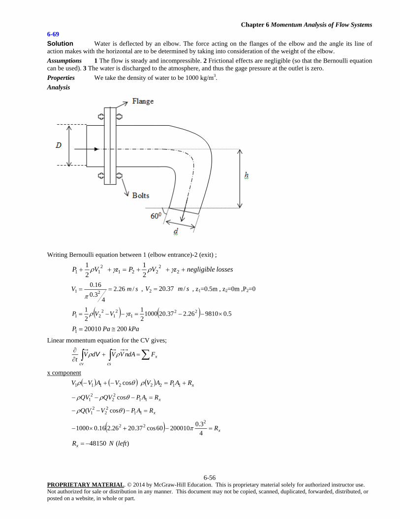
Chapter 6 Momentum Analysis of Flow Systems
PROPRIETARY MATERIAL. © 2014 by McGraw-Hill Education. This is proprietary material solely for authorized instructor use. Not authorized for sale or distribution in any manner. This document may not be copied, scanned, duplicated, forwarded, distributed, or posted on a website, in whole or part.
6-56
6-69
Solution Water is deflected by an elbow. The force acting on the flanges of the elbow and the angle its line of action makes with the horizontal are to be determined by taking into consideration of the weight of the elbow.
Assumptions 1 The flow is steady and incompressible. 2 Frictional effects are negligible (so that the Bernoulli equation can be used). 3 The water is discharged to the atmosphere, and thus the gage pressure at the outlet is zero.
Properties We take the density of water to be 1000 kg/m3.
Analysis
Writing Bernoulli equation between 1 (elbow entrance)-2 (exit) ;
lossesnegligiblezVPzVP 22
2212
11 2
1
2
1
smV /26.2
43.0
16.021
, smV /37.202 , z1=0.5m , z2=0m ,P2=0
5.0981026.237.2010002
1
2
1 221
21
221 zVVP
kPaPaP 200200101
Linear momentum equation for the CV gives;
x
cscv
FdAnVVdVt
V
x component
xRAPAVVAVV 11222111 cos
xRAPQVQV 112
22
1 cos
xRAPVVQ 112
22
1 )cos(
xR4
3.020001060cos37.2026.216.01000
222
)(48150 leftNRx

Chapter 6 Momentum Analysis of Flow Systems
PROPRIETARY MATERIAL. © 2014 by McGraw-Hill Education. This is proprietary material solely for authorized instructor use. Not authorized for sale or distribution in any manner. This document may not be copied, scanned, duplicated, forwarded, distributed, or posted on a website, in whole or part.
6-57
To include elbow weight we must modify y-momentum equation as follows:
y component:
yelbowcvwater RWWAVV ,222 sin0
yelbowcvwater RWWQV ,2
2 sin
yR 81.9503.0981060sin37.201000 2
)(359003 downNRy
These forces are exerted by elbow on water confined by CV. The force exerted by water on elbow is therefore;
kN 362 N36226635905248150 22RZ
and
82.4 457.7N 150,48
N 003,359tan
x
y
R
R
Therefore we could neglect the weight of the elbow.
Zy=-Ry
Zx=-Rx
Z=-R

Chapter 6 Momentum Analysis of Flow Systems
PROPRIETARY MATERIAL. © 2014 by McGraw-Hill Education. This is proprietary material solely for authorized instructor use. Not authorized for sale or distribution in any manner. This document may not be copied, scanned, duplicated, forwarded, distributed, or posted on a website, in whole or part.
6-58
6-70
Solution A horizontal water jet is deflected by a cone. The external force needed to maintain the motion of the cone is to be determined.
Assumptions 1 The flow is steady and incompressible. 2 The flow is uniform ine each section.
Properties We take the density of water to be 1000 kg/m3.
Analysis
We chose a CV moving with Vc to left. W1 and W2 are the relative velocities with respect to the CV. Conservation of mass gives
cv cs
W
cv dAnVVdt
.0 V ...........................1
Conservation of momentum gives
cv cs
dAnWWdWt
F
V ..............................2
From Eq. 1
02211 AWAW
jcj AVVAWAW 1122 , therefore A1 =A2 =Aj
From eq.2
1 2
222111 ..A A
x dAWCosWdAWWF
smVVWW cj /35102521
Then, CosAWAWF jjx .... 221
= jAWCos 22..1
= 22 12.04
351000140
Cos
Fx = -3241 N
Therefore,
Fx = 3241 N to left
=400
F
Water jet, Vj Vc = 10 m/s

Chapter 6 Momentum Analysis of Flow Systems
PROPRIETARY MATERIAL. © 2014 by McGraw-Hill Education. This is proprietary material solely for authorized instructor use. Not authorized for sale or distribution in any manner. This document may not be copied, scanned, duplicated, forwarded, distributed, or posted on a website, in whole or part.
6-59
6-71
Solution Water enters a two-armed sprinkler vertically, and leaves the nozzles horizontally at an angle to tangential direction. For a specified flow rate and discharge angle, the rate of rotation of the sprinkler and the torque required to prevent the sprinkler from rotating are to be determined. EES
Assumptions 1 The flow is uniform and cyclically steady (i.e., steady from a frame of reference rotating with the sprinkler head). 2 The water is discharged to the atmosphere, and thus the gage pressure at the nozzle outlet is zero. 3 Frictional effects and air drag of rotating components are neglected. 4 The nozzle diameter is small compared to the moment arm, and thus we use average values of radius and velocity at the outlet.
Properties We take the density of water to be 1000 kg/m3 = 1 kg/L.
Analysis We take the disk that encloses the sprinkler arms as the control volume, which is a stationary control volume. The conservation of mass equation for this symmetrical steady flow system is
mmm 21 . Noting that the two nozzles
are identical, we have 2/totaljet mm or
2/totaljet VV since the density of water is
constant. The average jet outlet velocity relative to the nozzle is
m/s 21.44L 1000
m 1
4/m) 012.0(
L/s 2/10 3
2jet
jet jet,
A
V r
V
The angular momentum equation about the axis of rotation can be expressed as inout
VmrVmrM where r is the
average moment arm, V is the average absolute speed (relative to an inertial reference frame), all moments in the counterclockwise direction are positive, and all moments in the clockwise direction are negative. Momentum flows in the clockwise direction (as in this case) are also negative. The absolute water jet speed in the tangential direction is the difference between the tangential component of the water jet speed and the nozzle speed rnrV 2nozzle . Thus,
rVVVV rr, t cos jet,nozzlet jet,jet, . Then the angular momentum equation becomes
2 , jet,jet,221, jet,jet,11shaftT tt VmrVmr )cos()cos(T 222, jet,jet,22111, jet,jet,11shaft rVmrrVmr rr
Noting that rrr 21 , 21 , rrr VVV jet,2, jet,1, jet, , and, the angular momentum equation becomes
)cos(T jet,totalshaft rVVr r
(a) In the case of free spin with no frictional effects, we have Tshaft = 0 and thus 0cos jet, rV r . Then angular speed
and the rate of rotation of sprinkler head becomes
rpm 528
min 1
s 60
2
rad/s 26.55
2and rad/s 26.55
m 40.0
m/s)cos60 21.44(cosr jet,
nr
V
(b) When the sprinkler is prevented from rotating, we have = 0. Then the required torque becomes
mN 88.4
2 jet,totalshaftm/skg 1
N 160cos)m/s 21.44)(L/s 10)(kg/L 1)(m 4.0(cos T rVVr
Discussion The rate of rotation determined in (a) will be lower in reality because of frictional effects and air drag.
r1 = 40 cm r2 = 40 cm
= 60°
1
2
A
= 60°
Vjet, 2
Vjet, 1
Tshaft

Chapter 6 Momentum Analysis of Flow Systems
PROPRIETARY MATERIAL. © 2014 by McGraw-Hill Education. This is proprietary material solely for authorized instructor use. Not authorized for sale or distribution in any manner. This document may not be copied, scanned, duplicated, forwarded, distributed, or posted on a website, in whole or part.
6-60
6-72 Solution Water enters a two-armed sprinkler vertically, and leaves the nozzles horizontally at an angle to tangential direction. For a specified flow rate and discharge angle, the rate of rotation of the sprinkler and the torque required to prevent the sprinkler from rotating are to be determined. Assumptions 1 The flow is uniform and cyclically steady (i.e., steady from a frame of reference rotating with the sprinkler head). 2 The water is discharged to the atmosphere, and thus the gage pressure at the nozzle outlet is zero. 3 Frictional effects and air drag of rotating components are neglected. 4 The nozzle diameter is small compared to the moment arm, and thus we use average values of radius and velocity at the outlet. Properties We take the density of water to be 1000 kg/m3 = 1 kg/L. Analysis We take the disk that encloses the sprinkler arms as the control volume, which is a stationary control volume. The conservation of mass equation for this symmetrical steady flow system is
mmm 21 . Noting that the two nozzles
are identical, we have 2/totaljet mm or
2/totaljet VV since the density of water is
constant. The average jet outlet velocity relative to the nozzle is
m/s 21.44L 1000
m 1
4/m) 012.0(
L/s 2/10 3
2jet
jet jet,
A
V r
V
The angular momentum equation about the axis of rotation can be expressed as inout
VmrVmrM where r is the
average moment arm, V is the average absolute speed (relative to an inertial reference frame), all moments in the counterclockwise direction are positive, and all moments in the clockwise direction are negative. Momentum flows in the clockwise direction (as in this case) are also negative. The absolute water jet speed in the tangential direction is the difference between the tangential component of the water jet speed and the nozzle speed rnrV 2nozzle . Thus,
rVVVV rr, t cos jet,nozzlet jet,jet, . Then the angular momentum equation becomes
2 , jet,jet,221, jet,jet,11shaftT tt VmrVmr )cos()cos(T 222, jet,jet,22111, jet,jet,11shaft rVmrrVmr rr
Noting that 21 , rrr VVV jet,2, jet,1, jet, , and, the angular momentum equation becomes
)]cos()cos([T 2 jet,21 jet,1jetshaft rVrrVrV rr or ])(cos)[(T 22
21 jet,21jetshaft rrVrrV r
(a) In the case of free spin with no frictional effects, we have Tshaft = 0 and thus )(cos)(0 22
21 jet,21 rrVrr r .
Then angular speed and the rate of rotation of sprinkler head becomes
and
rpm 422
rpm 2.422min 1
s 60
2
rad/s 21.44
2
rad/s .2144m) 20.0(m) 60.0(
m/s)cos60 21.44)(m2.06.0(cos))(222
22
1
r jet,21
n
rr
Vrr
(b) When the sprinkler is prevented from rotating, we have = 0. Then the required torque becomes
mN 88.4
2 jet,jet21shaftm/skg 1
N 160cos)m/s 21.44)(L/s 2/10)(kg/L 1)(m 2.06.0(cos)( T rVVrr
Discussion The rate of rotation determined in (a) will be lower in reality because of frictional effects and air drag.
r1 = 60 cm r2 = 20 cm
60°
1
2
A
= 60°
Vjet, 2
Vjet, 1
A
Tshaft

Chapter 6 Momentum Analysis of Flow Systems
PROPRIETARY MATERIAL. © 2014 by McGraw-Hill Education. This is proprietary material solely for authorized instructor use. Not authorized for sale or distribution in any manner. This document may not be copied, scanned, duplicated, forwarded, distributed, or posted on a website, in whole or part.
6-61
6-73
Solution A horizontal water jet strikes a vertical stationary flat plate normally at a specified velocity. For a given flow velocity, the anchoring force needed to hold the plate in place is to be determined.
Assumptions 1 The flow is steady and incompressible. 2 The water splatters off the sides of the plate in a plane normal to the jet. 3 The water jet is exposed to the atmosphere, and thus the pressure of the water jet and the splattered water is the atmospheric pressure which is disregarded since it acts on the entire control surface. 4 The vertical forces and momentum fluxes are not considered since they have no effect on the horizontal reaction force. 5 Jet flow is nearly uniform and thus the momentum-flux correction factor can be taken to be unity, 1.
Properties We take the density of water to be 1000 kg/m3.
Analysis We take the plate as the control volume such that it contains the entire plate and cuts through the water jet and the support bar normally, and the direction of flow as the positive direction of x axis. We take the reaction force to be in the negative x direction. The momentum equation for steady flow in the x (flow) direction reduces in this case to
inout
VmVmF
Rx i i i Rx iF mV F mV
We note that the reaction force acts in the opposite direction to flow, and we should not forget the negative sign for forces and velocities in the negative x-direction. The mass flow rate of water is
2 23 (0.06 m)
(1000 kg/m ) (25 m/s) 70.6858 kg/s4 4
Dm AV V
V
Substituting, the reaction force is determined to be
1 (70.6858 kg/s)(25 m/s) 1767 NRxF 1770 N
Therefore, a force of approximately 1770 N must be applied to the plate in the opposite direction to the flow to hold it in place.
Discussion In reality, some water may be scattered back, and this would add to the reaction force of water. If we do not approximate the water jet as uniform, the momentum flux correction factor would factor in. For example, if = 1.03 (approximate value for fully developed pipe flow), the force would increase by 3%. This is because the actual nonuniform jet has more momentum than the uniform jet.
25 m/s
6 cm
FRx

Chapter 6 Momentum Analysis of Flow Systems
PROPRIETARY MATERIAL. © 2014 by McGraw-Hill Education. This is proprietary material solely for authorized instructor use. Not authorized for sale or distribution in any manner. This document may not be copied, scanned, duplicated, forwarded, distributed, or posted on a website, in whole or part.
6-62
6-74
Solution Steady developing laminar flow is considered in a constant horizontal diameter discharge pipe. A relation is to be obtained for the horizontal force acting on the bolts that hold the pipe.
Assumptions 1 The flow is steady, laminar, and incompressible. 2 The flow is fully developed at the end of the pipe section considered. 3 The velocity profile at the pipe inlet is uniform and thus the momentum-flux correction factor is 1 = 1. 4 The momentum-flux correction factor is = 2 at the outlet.
Analysis We take the developing flow section of the pipe (including the water inside) as the control volume. We assume the reaction force to act in the positive direction. Noting that the flow is incompressible and thus the average velocity is constant V1 = V2 = V, the momentum equation for steady flow in the z (flow) direction in this case reduces to
inout
VmVmF
VmVmAPAPF ccR 1221
VmDPP
VmAPP
VmAPPF
c
cR
4/)(
)21()(
)()(
221
21
2121
Or, using the definition of the mass flow rate,
222
21 ]4/[4/)( VDDPPFR
Or,
221
2
)(4
VPPD
FR
Discussion Note that the cause of this reaction force is non-uniform velocity profile at the end.

Chapter 6 Momentum Analysis of Flow Systems
PROPRIETARY MATERIAL. © 2014 by McGraw-Hill Education. This is proprietary material solely for authorized instructor use. Not authorized for sale or distribution in any manner. This document may not be copied, scanned, duplicated, forwarded, distributed, or posted on a website, in whole or part.
6-63
6-75
Solution A fireman was hit by a nozzle held by a tripod with a rated holding force. The accident is to be investigated by calculating the water velocity, the flow rate, and the nozzle velocity.
Assumptions 1 The flow is steady and incompressible. 2 The water jet is exposed to the atmosphere, and thus the pressure of the water jet is the atmospheric pressure, which is disregarded since it acts on all surfaces. 3 Gravitational effects and vertical forces are disregarded since the horizontal resistance force is to be determined. 4 Jet flow is nearly uniform and thus the momentum-flux correction factor can be taken to be unity, 1. 5 Upstream pressure and momentum effects are ignored.
Properties We take the density of water to be 1000 kg/m3.
Analysis We take the nozzle and the horizontal portion of the hose as the system such that water enters the control volume vertically and outlets horizontally (this way the pressure force and the momentum flux at the inlet are in the vertical direction, with no contribution to the force balance in the horizontal direction, and designate the entrance by 1 and the outlet by 2. We also designate the horizontal coordinate by x (with the direction of flow as being the positive direction).
The momentum equation for steady flow is inout
VmVmF
. We let the horizontal force applied by
the tripod to the nozzle to hold it be FRx, and assume it to be in the positive x direction. Then the momentum equation along the x direction becomes
22
32
22
4
m) (0.05)kg/m 1000(
N 1
m/skg 1N) (1800
40 VV
DAVVVmVmF eRx
Solving for the water outlet velocity gives V = 30.3 m/s. Then the water flow rate becomes
/sm 0.0595 3 m/s) (30.34
m) (0.05
4
22 V
DAVV
When the nozzle was released, its acceleration must have been
m/s 180N 1
m/skg 1
kg 10
N 1800 2
2
nozzlenozzle
m
Fa
Assuming the reaction force acting on the nozzle and thus its acceleration to remain constant, the time it takes for the nozzle to travel 60 cm and the nozzle velocity at that moment were (note that both the distance x and the velocity V are zero at time t = 0)
sa
xtatx 0816.0
m/s 180
m) 6.0(22
22
21
m/s 14.7 s) 0816.0)(m/s 180( 2atV
Thus we conclude that the nozzle hit the fireman with a velocity of 14.7 m/s.
Discussion Engineering analyses such as this one are frequently used in accident reconstruction cases, and they often form the basis for judgment in courts.
Tripod
Nozzle
D = 5 cm
FRx

Chapter 6 Momentum Analysis of Flow Systems
PROPRIETARY MATERIAL. © 2014 by McGraw-Hill Education. This is proprietary material solely for authorized instructor use. Not authorized for sale or distribution in any manner. This document may not be copied, scanned, duplicated, forwarded, distributed, or posted on a website, in whole or part.
6-64
6-76
Solution During landing of an airplane, the thrust reverser is lowered in the path of the exhaust jet, which deflects the exhaust and provides braking. The thrust of the engine and the braking force produced after the thrust reverser is deployed are to be determined.
Assumptions 1 The flow of exhaust gases is steady and one-dimensional. 2 The exhaust gas stream is exposed to the atmosphere, and thus its pressure is the atmospheric pressure. 3 The velocity of exhaust gases remains constant during reversing. 4 Jet flow is nearly uniform and thus the momentum-flux correction factor can be taken to be unity, 1.
Analysis (a) The thrust exerted on an airplane is simply the momentum flux of the combustion gases in the reverse direction,
N 5400
2m/skg 1
N 1m/s) kg/s)(300 18(Thrust exexVm
(b) We take the thrust reverser as the control volume such that it cuts through both exhaust streams normally and the connecting bars to the airplane, and the direction of airplane as the positive direction of x axis. The momentum equation for steady flow in the x direction reduces to
inout
VmVmF
)20cos1( )( )cos20( iRxRx VmFVmVmF
Substituting, the reaction force is determined to be
N 077,10m/s) kg/s)(300 18)(30cos1( RxF
The breaking force acting on the plane is equal and opposite to this force,
N 10,100 N 077,10breakingF
Therefore, a braking force of 10,100 N develops in the opposite direction to flight.
Discussion This problem can be solved more generally by measuring the reversing angle from the direction of exhaust gases ( = 0 when there is no reversing). When < 90, the reversed gases are discharged in the negative x direction, and the momentum equation reduces to
)cos1( )( )cos( iRxRx VmFVmVmF
This equation is also valid for >90 since cos(180-) = - cos. Using = 150, for example, gives
)30cos1( )150cos1( iiRx VmVmF , which is identical to the solution above.
150 300 m/s
FRx
= 150
FRx
Vm
Vm
x
Control volume

Chapter 6 Momentum Analysis of Flow Systems
PROPRIETARY MATERIAL. © 2014 by McGraw-Hill Education. This is proprietary material solely for authorized instructor use. Not authorized for sale or distribution in any manner. This document may not be copied, scanned, duplicated, forwarded, distributed, or posted on a website, in whole or part.
6-65
6-77
Solution The previous problem is reconsidered. The effect of thrust reverser angle on the braking force exerted on the airplane as the reverser angle varies from 0 (no reversing) to 180 (full reversing) in increments of 10 is to be investigated.
Analysis The EES Equations window is printed below, followed by the tabulated and plotted results.
V_jet=250 "m/s"
m_dot=18 "kg/s"
F_Rx=(1-cos(alpha))*m_dot*V_jet "N"
Reversing angle,
Braking force
Fbrake, N
0
10
20
30
40
50
60
70
80
90
100
110
120
130
140
150
160
170
180
0
68
271
603
1053
1607
2250
2961
3719
4500
5281
6039
6750
7393
7947
8397
8729
8932
9000
Discussion As expected, the braking force is zero when the angle is zero (no deflection), and maximum when the angle is 180o (completely reversed). Of course, it is impossible to completely reverse the flow, since the jet exhaust cannot be directed back into the engine.

Chapter 6 Momentum Analysis of Flow Systems
PROPRIETARY MATERIAL. © 2014 by McGraw-Hill Education. This is proprietary material solely for authorized instructor use. Not authorized for sale or distribution in any manner. This document may not be copied, scanned, duplicated, forwarded, distributed, or posted on a website, in whole or part.
6-66
6-78E
Solution The rocket of a spacecraft is fired in the opposite direction to motion. The deceleration, the velocity change, and the thrust are to be determined.
Assumptions 1 The flow of combustion gases is steady and one-dimensional during the firing period, but the flight of the spacecraft is unsteady. 2 There are no external forces acting on the spacecraft, and the effect of pressure force at the nozzle outlet is negligible. 3 The mass of discharged fuel is negligible relative to the mass of the spacecraft, and thus the spacecraft may be treated as a solid body with a constant mass. 4 The nozzle is well-designed such that the effect of the momentum-flux correction factor is negligible, and thus 1.
Analysis (a) We choose a reference frame in which the control volume moves with the spacecraft. Then the velocities of fluid steams become simply their relative velocities (relative to the moving body). We take the direction of motion of the spacecraft as the positive direction along the x axis. There are no external forces acting on the spacecraft, and its mass is nearly constant. Therefore, the spacecraft can be treated as a solid body with constant mass, and the momentum equation in this case is
ffCV Vm
dt
VdmVmVm
dt
Vmd
spacespace
inout
)(
0
Noting that the motion is on a straight line and the discharged gases move in the positive x direction (to slow down the spacecraft), we write the momentum equation using magnitudes as
ff
ff Vm
m
dt
dVVm
dt
dVm
space
spacespacespace
Substituting, the deceleration of the spacecraft during the first 5 seconds is determined to be
ft/s 30.0 2 ft/s) (5000lbm 25,000
lbm/s 150
space
spacespace f
fV
m
m
dt
dVa
(b) Knowing the deceleration, which is constant, the velocity change of the spacecraft during the first 5 seconds is determined from the definition of acceleration dtdVa / spacespace to be
ft/s 150 )s 5)(ft/s .030( 2spacespacespacespace taVdtadV
(c) The thrust exerted on the system is simply the momentum flux of the combustion gases in the reverse direction,
2
1 lbfThrust 150 lbm/s 5000 ft/s 23 290 lbf
32.2 lbm ft/sR f fF m V ,
23,300 lbf
Therefore, if this spacecraft were attached somewhere, it would exert a force of 23,300 lbf (equivalent to the weight of 23,300 lbm of mass on earth) to its support in the negative x direction.
Discussion In Part (b) we approximate the deceleration as constant. However, since mass is lost from the spacecraft during the time in which the jet is on, a more accurate solution would involve solving a differential equation. Here, the time span is short, and the lost mass is likely negligible compared to the total mass of the spacecraft, so the more complicated analysis is not necessary.
2000 ft/s
25,000 lbm
150 lbm/s 5000 ft/s
x

Chapter 6 Momentum Analysis of Flow Systems
PROPRIETARY MATERIAL. © 2014 by McGraw-Hill Education. This is proprietary material solely for authorized instructor use. Not authorized for sale or distribution in any manner. This document may not be copied, scanned, duplicated, forwarded, distributed, or posted on a website, in whole or part.
6-67
6-79
Solution An ice skater is holding a flexible hose (essentially weightless) which directs a stream of water horizontally at a specified velocity. The velocity and the distance traveled in 5 seconds, and the time it takes to move 5 m and the velocity at that moment are to be determined.
Assumptions 1 Friction between the skates and ice is negligible. 2 The flow of water is steady and one-dimensional (but the motion of skater is unsteady). 3 The ice skating arena is level, and the water jet is discharged horizontally. 4 The mass of the hose and the water in it is negligible. 5 The skater is standing still initially at t = 0. 6 Jet flow is nearly uniform and thus the momentum-flux correction factor can be taken to be unity, 1.
Properties We take the density of water to be 1000 kg/m3.
Analysis (a) The mass flow rate of water through the hose is
kg/s14.3m/s) (104
m) (0.02) kg/m1000(
4
23
2
V
DAVm
The thrust exerted on the skater by the water stream is simply the momentum flux of the water stream, and it acts in the reverse direction,
(constant) N 4.31m/s kg1
N 1m/s) kg/s)(1014.3(Thrust
2
VmF
The acceleration of the skater is determined from Newton’s 2nd law of motion F = ma where m is the mass of the skater,
22
m/s 0.523N 1
m/skg 1
kg 60
N 4.31
m
Fa
Note that thrust and thus the acceleration of the skater is constant. The velocity of the skater and the distance traveled in 5 s are
m 6.54
m/s 2.62
22
212
21
2skater
s) 5)(m/s 0.523(
s) 5)(m/s 0.523(
atx
atV
(b) The time it will take to move 5 m and the velocity at that moment are
m/s 2.3
s 4.4
s) 4.4)(m/s 0.523(
m/s 0.523
m) 5(22
2skater
22
21
atV
a
xtatx
Discussion In reality, the velocity of the skater will be lower because of friction on ice and the resistance of the hose to follow the skater. Also, in the Vm expressions, V is the fluid stream speed relative to a fixed point. Therefore, the correct
expression for thrust is )( skaterjet VVmF , and the analysis above is valid only when the skater speed is low relative to
the jet speed. An exact analysis would result in a differential equation.
10 m/s
Hose D=2 cm
F

Chapter 6 Momentum Analysis of Flow Systems
PROPRIETARY MATERIAL. © 2014 by McGraw-Hill Education. This is proprietary material solely for authorized instructor use. Not authorized for sale or distribution in any manner. This document may not be copied, scanned, duplicated, forwarded, distributed, or posted on a website, in whole or part.
6-68
6-80
Solution A water jet hits a stationary cone, such that the flow is diverted equally in all directions at 45. The force required to hold the cone in place against the water stream is to be determined.
Assumptions 1 The flow is steady and incompressible. 2 The water jet is exposed to the atmosphere, and thus the pressure of the water jet before and after the split is the atmospheric pressure which is disregarded since it acts on all surfaces. 3 The gravitational effects are disregarded. 4 Jet flow is nearly uniform and thus the momentum-flux correction factor can be taken to be unity, 1.
Properties We take the density of water to be 1000 kg/m3.
Analysis The mass flow rate of water jet is
kg/s90.58m/s) (304
m) (0.05) kg/m1000(
4
23
2
V
DAVm V
We take the diverting section of water jet, including the cone as the control volume, and designate the entrance by 1 and the outlet after divergence by 2. We also designate the horizontal coordinate by x with the direction of flow as being the positive direction and the vertical coordinate by y.
The momentum equation for steady flow is inout
VmVmF
. We let the x- and y- components of the anchoring
force of the cone be FRx and FRy, and assume them to be in the positive directions. Noting that V2 = V1 = V and mmm 12 , the momentum equations along the x and y axes become
axis) x about symmetry of (because 0
)1(coscos 12
Ry
Rx
F
VmVmVmF
Substituting the given values,
0
N 518
Ry
Rx
F
F2m/s kg1
N 11)-m/s)(cos45 kg/s)(3090.58(
The negative value for FRx indicates that the assumed direction is wrong, and should be reversed. Therefore, a force of 518 N must be applied to the cone in the opposite direction to flow to hold it in place. No holding force is necessary in the vertical direction due to symmetry and neglecting gravitational effects.
Discussion In reality, the gravitational effects will cause the upper part of flow to slow down and the lower part to speed up after the split. But for short distances, these effects are negligible.
30 m/s
5 cm
FRx

Chapter 6 Momentum Analysis of Flow Systems
PROPRIETARY MATERIAL. © 2014 by McGraw-Hill Education. This is proprietary material solely for authorized instructor use. Not authorized for sale or distribution in any manner. This document may not be copied, scanned, duplicated, forwarded, distributed, or posted on a website, in whole or part.
6-69
6-81
Solution Water is flowing into and discharging from a pipe U-section with a secondary discharge section normal to return flow. Net x- and z- forces at the two flanges that connect the pipes are to be determined.
Assumptions 1 The flow is steady and incompressible. 2 The weight of the U-turn and the water in it is negligible. 4 The momentum-flux correction factor for each inlet and outlet is given to be = 1.03.
Properties We take the density of water to be 1000 kg/m3.
Analysis The flow velocities of the 3 streams are
m/s 01.28]4/m) 05.0()[kg/m (1000
kg/s 55
)4/( 2321
1
1
11
D
m
A
mV
m/s 093.5]4/m) 10.0()[kg/m (1000
kg/s 40
)4/( 2322
2
2
22
D
m
A
mV
m/s 22.21]4/m) 03.0()[kg/m (1000
kg/s 15
)4/( 2323
3
3
33
D
m
A
mV
We take the entire U-section as the control volume. We designate the horizontal coordinate by x with the direction of incoming flow as being the positive direction and the vertical coordinate by z. The momentum equation for steady flow is
inout
VmVmF
. We let the x- and z- components of the anchoring force of the cone be FRx and FRz, and
assume them to be in the positive directions. Then the momentum equations along the x and z axes become
0-0
)( )(
3333
1122221111222211
VmFVmF
VmVmAPAPFVmVmAPAPF
RzRz
RxRx
Substituting the given values,
N 2390
kN 386.2
m/skg 1000
kN 1m/s) 1kg/s)(28.0 55(
m/skg 1000
kN 1m/s) 3kg/s)(5.09 40(03.1
4
m) (0.10]kN/m )100150[(
4
m) (0.05]kN/m )100200[(
22
22
22
RxF
N 328
N .8327
m/skg 1
N 1m/s) 2kg/s)(21.2 15(03.1
2RzF
The negative value for FRx indicates the assumed direction is wrong, and should be reversed. Therefore, a force of 2390 N acts on the flanges in the opposite direction. A vertical force of 328 N acts on the flange in the vertical direction.
Discussion To assess the significance of gravity forces, we estimate the weight of the weight of water in the U-turn and compare it to the vertical force. Assuming the length of the U-turn to be 0.5 m and the average diameter to be 7.5 cm, the mass of the water becomes
kg2.2m) (0.54
m) (0.075) kg/m1000(
4
23
2
L
DALm V
whose weight is 2.29.81 = 22 N, which is much less than 328, but still significant. Therefore, disregarding the gravitational effects is a reasonable assumption if great accuracy is not required.
15 kg/s
1
2 3
40 kg/s
55 kg/s
FRz
FRx

Chapter 6 Momentum Analysis of Flow Systems
PROPRIETARY MATERIAL. © 2014 by McGraw-Hill Education. This is proprietary material solely for authorized instructor use. Not authorized for sale or distribution in any manner. This document may not be copied, scanned, duplicated, forwarded, distributed, or posted on a website, in whole or part.
6-70
6-82 Solution Indiana Jones is to ascend a building by building a platform, and mounting four water nozzles pointing down at each corner. The minimum water jet velocity needed to raise the system, the time it will take to rise to the top of the building and the velocity of the system at that moment, the additional rise when the water is shut off, and the time he has to jump from the platform to the roof are to be determined. Assumptions 1 The air resistance is negligible. 2 The flow of water is steady and one-dimensional (but the motion of platform is unsteady). 3 The platform is still initially at t = 0. 4 Jet flow is nearly uniform and thus the momentum-flux correction factor can be taken to be unity, 1. Properties We take the density of water to be 1000 kg/m3. Analysis (a) The total mass flow rate of water through the 4 hoses and the total weight of the platform are
2 23 (0.04 m)
4 4(1000 kg/m ) (18 m/s) 90.4779 kg/s4 4
Dm AV V
22
1 N(150 kg)(9.81 m/s ) 1471.5 N
1 kg m/sW mg
We take the platform as the system. The momentum equation for steady flow is inout
VmVmF
. The
minimum water jet velocity needed to raise the platform is determined by setting the net force acting on the platform equal to zero,
2min
2
minminminmin 44 0)( V
DVAVVmWVmW
Solving for Vmin and substituting, 2
min 2 3 2
1471.5 N 1kg m/s17.1098 m/s
(1000 kg/m ) (0.04 m) 1N
WV
D
17.1 m/s
(b) We let the vertical reaction force (assumed upwards) acting on the platform be FRz. Then the momentum equation in the vertical direction becomes
2kg m 1kg m/s( ) 0 (1471.5 N) (90.4779 )(18 ) 157.101 N
s s 1NRz RzF W m V mV F W mV
The upward thrust acting on the platform is equal and opposite to this reaction force, and thus F = 156.6 N. Then the acceleration and the ascending time to rise 10 m and the velocity at that moment become
2
2157.101 N 1 kg m/s1.0473 m/s
150 kg 1 N
Fa
m
212 2
2 2(10 m) 4.36989 s
1.0473 m/s
xx at t
a 4.37 s
and
2(1.0473 m/s )(4.36989 s) 4.5766 m/sV at
(c) When the water is shut off at 10 m height (where the velocity is 4.57 m/s), the platform will decelerate under the influence of gravity, and the time it takes to come to a stop and the additional rise above 10 m become
00 2
4.5766 m/s0 0.46652 s
9.81 m/s
VV V gt t
g
2 2 21 10 2 2(4.5766 m/s)(0.46652 s) (9.81 m/s )(0.46652 s) 1.0675 mz V t gt 1.07 m
Therefore, Jones has 20.46652 = 0.93304 0.933 s to jump off from the platform to the roof since it takes another 0.466 s for the platform to descend to the 10 m level. Discussion Like most stunts in the Indiana Jones movies, this would not be practical in reality.
18 m/s
D = 4 cm
z
x
FRy

Chapter 6 Momentum Analysis of Flow Systems
PROPRIETARY MATERIAL. © 2014 by McGraw-Hill Education. This is proprietary material solely for authorized instructor use. Not authorized for sale or distribution in any manner. This document may not be copied, scanned, duplicated, forwarded, distributed, or posted on a website, in whole or part.
6-71
6-83E
Solution A box-enclosed fan is faced down so the air blast is directed downwards, and it is to be hovered by increasing the blade rpm. The required blade rpm, air outlet velocity, the volumetric flow rate, and the minimum mechanical power are to be determined.
Assumptions 1 The flow of air is steady and incompressible. 2 The air leaves the blades at a uniform velocity at atmospheric pressure, and thus the momentum-flux correction factor can be taken to be unity, 1. 3 Air approaches the blades from the top through a large area at atmospheric pressure with negligible velocity. 4 The frictional effects are negligible, and thus the entire mechanical power input is converted to kinetic energy of air (no conversion to thermal energy through frictional effects). 5 The change in air pressure with elevation is negligible because of the low density of air. 6 There is no acceleration of the fan, and thus the lift generated is equal to the total weight.
Properties The density of air is given to be 0.078 lbm/ft3.
Analysis (a) We take the control volume to be a vertical hyperbolic cylinder bounded by streamlines on the sides with air entering through the large cross-section (section 1) at the top and the fan located at the narrow cross-section at the bottom (section 2), and let its centerline be the z axis with upwards being the positive direction.
The momentum equation for steady flow is inout
VmVmF
. Noting that the only force acting on the
control volume is the total weight W and it acts in the negative z direction, the momentum equation along the z axis gives
)( 0)( 22
22222 A
WVAVVAVVmWVmW
where A is the blade span area,
222 ft 069.74/ft) 3(4/ DA
Then the discharge velocity to produce 5 lbf of upward force becomes
ft/s 17.1
lbf 1
ft/slbm 32.2
)ft )(7.069lbm/ft (0.078
lbf 5 2
232V
(b) The volume flow rate and the mass flow rate of air are determined from their definitions,
/sft 121 3 ft/s) 1.17)(ft 069.7( 22AVV
lbm/s 43.9/s)ft 121)(lbm/ft 078.0( 33 V m
(c) Noting that P1 = P2 = Patm, V1 0, the elevation effects are negligible, and the frictional effects are disregarded, the energy equation for the selected control volume reduces to
lossmech,turbine2
222
upump,1
211
22EWgz
VPmWgz
VPm
2
22
ufan,V
mW
Substituting,
W64.3
ft/slbf 0.73756
W 1
ft/slbm 2.32
lbf 1
2
ft/s) (18.0lbm/s) 43.9(
2 2
222
ufan,V
mW
Therefore, the minimum mechanical power that must be supplied to the air stream is 64.3 W.
Discussion The actual power input to the fan will be considerably larger than the calculated power input because of the fan inefficiency in converting mechanical work to kinetic energy.
600 rpm
FRy 1
2

Chapter 6 Momentum Analysis of Flow Systems
PROPRIETARY MATERIAL. © 2014 by McGraw-Hill Education. This is proprietary material solely for authorized instructor use. Not authorized for sale or distribution in any manner. This document may not be copied, scanned, duplicated, forwarded, distributed, or posted on a website, in whole or part.
6-72
6-84
Solution A plate is maintained in a horizontal position by frictionless vertical guide rails. The underside of the plate is subjected to a water jet. The minimum mass flow rate minm to just levitate the plate is to be determined, and a relation is
to be obtained for the steady state upward velocity. Also, the integral that relates velocity to time when the water is first turned on is to be obtained.
Assumptions 1 The flow of water is steady and one-dimensional. 2 The water jet splatters in the plane of he plate. 3 The vertical guide rails are frictionless. 4 Times are short, so the velocity of the rising jet can be considered to remain constant with height. 5 At time t = 0, the plate is at rest. 6 Jet flow is nearly uniform and thus the momentum-flux correction factor can be taken to be unity, 1.
Analysis (a) We take the plate as the system. The momentum equation for steady flow is
inout
VmVmF
. Noting that JAVm where A is the cross-sectional area of the water jet and W = mpg, the
minimum mass flow rate of water needed to raise the plate is determined by setting the net force acting on the plate equal to zero,
gAmmAVmmgmVmWVmW pp minJminminJminJmin )/( 0
For minmm , a relation for the steady state upward velocity V is obtained setting the upward impulse applied by water jet
to the weight of the plate (during steady motion, the plate velocity V is constant, and the velocity of water jet relative to plate is VJ –V),
A
gm
A
mV
A
gmVVVVAgmVVmW
ppJJpJ
)( )( 2
(b) At time t = 0 the plate is at rest (V = 0), and it is subjected to water jet with minmm and thus the net force acting on it is greater than the
weight of the plate, and the difference between the jet impulse and the weight will accelerate the plate upwards. Therefore, Newton’s 2nd law F = ma = mdV/dt in this case can be expressed as
dt
dVmgmVVAamWVVm ppJpJ 2)( )(
Separating the variables and integrating from t = 0 when V = 0 to t = t when V = V gives the desired integral,
V
2 0 0
tp
tJ p
m dVdt
A(V V ) m g
V
2 0
p
J p
m dVt
A(V V ) m g
Discussion This integral can be performed with the help of integral tables. But the relation obtained will be implicit in V.
mp
Guide rails
m
Nozzle
FRz
W = mp g
.

Chapter 6 Momentum Analysis of Flow Systems
PROPRIETARY MATERIAL. © 2014 by McGraw-Hill Education. This is proprietary material solely for authorized instructor use. Not authorized for sale or distribution in any manner. This document may not be copied, scanned, duplicated, forwarded, distributed, or posted on a website, in whole or part.
6-73
6-85
Solution A walnut is to be cracked by dropping it from a certain height to a hard surface. The minimum height required is to be determined.
Assumptions 1 The force remains constant during the cracking period of the walnut. 2 The air resistance is negligible.
Analysis We take the x axis as the upward vertical direction. Newton’s 2nd law F = ma = mdV/dt can be expressed as
)( finalstrike VVmVmtF m
tFV
strike
since the force remains constant and the final velocity is zero. Substituting,
m/s 8N 1
m/s kg1
kg0.050
s) N)(0.002 200( 2
strike
m
tFV
The elevation that will result at this value of velocity can be determined from the conservation of energy principle (in this case potential energy being converted to kinetic energy) to be
finalinitial kepe 2strike2
1 mVmgh g
Vh
2
2strike
Substituting, the required height at which the walnut needs to be dropped becomes
m 3.26)m/s 2(9.81
m/s) 8(
2 2
22strike
g
Vh
Discussion Note that a greater height will be required in reality because of air friction.
m
V
h

Chapter 6 Momentum Analysis of Flow Systems
PROPRIETARY MATERIAL. © 2014 by McGraw-Hill Education. This is proprietary material solely for authorized instructor use. Not authorized for sale or distribution in any manner. This document may not be copied, scanned, duplicated, forwarded, distributed, or posted on a website, in whole or part.
6-74
6-86
Solution A vertical water jet strikes a horizontal stationary plate normally. The maximum weight of the plate that can be supported by the water jet at a specified height is to be determined.
Assumptions 1 The flow of water at the nozzle outlet is steady and incompressible. 2 The water splatters in directions normal to the approach direction of the water jet. 3 The water jet is exposed to the atmosphere, and thus the pressure of the water jet and the splattered water leaving the control volume is atmospheric pressure . 4 Friction between the water and air is negligible. 5 The effect of the momentum-flux correction factor is negligible, and thus 1 for the jet.
Properties We take the density of water to be 1000 kg/m3.
Analysis We take the x axis as the upward vertical direction. We also take point 1 at the point where the water jet leaves the nozzle, and point 2 at the point where the jet strikes the flat plate. Noting that water jet is exposed to the atmosphere, we have P1 = P2 = Patm , Also, z1 = 0 and z2 = h. Then the Bernoulli Equation simplifies to
ghVVhg
V
g
Vz
g
V
g
Pz
g
V
g
P2
200
20
222
12
22
21
2
222
1
211
Substituting, the jet velocity when the jet strikes the flat plate is determined to be
m/s 63.13)m 2)(m/s 81.9(2)m/s 15( 222 V
The mass flow rate of water is
kg/s73.57m/s) (154
m) (0.07) kg/m1000(
4
23
2
V
DVAm cV
We take the thin region below the flat plate as the control volume such that it cuts through the incoming water jet. The weight W of the flat plate acts downward as a vertical force on the CV. Noting that water jet splashes out horizontally after it strikes the plate, the momentum equation for steady flow in the x (flow) direction reduces to
inout
VmVmF
22 VmWVmW
Substituting, the weight of the flat plate is determined to be
N 771
2m/s kg1
N 1m/s) 36 kg/s)(13.73.57(W
Discussion Note that this weight corresponds to a plate mass of 771/9.81 = 78.5 kg of mass. Also, a smaller mass will be held in balance at a greater height and a larger mass at a smaller height.
W
V2
h
1
2

Chapter 6 Momentum Analysis of Flow Systems
PROPRIETARY MATERIAL. © 2014 by McGraw-Hill Education. This is proprietary material solely for authorized instructor use. Not authorized for sale or distribution in any manner. This document may not be copied, scanned, duplicated, forwarded, distributed, or posted on a website, in whole or part.
6-75
6-87
Solution A vertical water jet strikes a horizontal stationary plate normally. The maximum weight of the plate that can be supported by the water jet at a specified height is to be determined.
Assumptions 1 The flow of water at the nozzle outlet is steady and incompressible. 2 The water splatters in directions normal to the approach direction of the water jet. 3 The water jet is exposed to the atmosphere, and thus the pressure of the water jet and the splattered water leaving the control volume is atmospheric pressure . 4 Friction between the water and air is negligible. 5 The effect of the momentum-flux correction factor is negligible, and thus 1 for the jet.
Properties We take the density of water to be 1000 kg/m3.
Analysis We take the x axis as the upward vertical direction. We also take point 1 at the point where the water jet leaves the nozzle, and point 2 at the point where the jet strikes the flat plate. Noting that water jet is exposed to the atmosphere, we have P1 = P2 = Patm , Also, z1 = 0 and z2 = h. Then the Bernoulli Equation simplifies to
ghVVhg
V
g
Vz
g
V
g
Pz
g
V
g
P2
200
20
222
12
22
21
2
222
1
211
Substituting, the jet velocity when the jet strikes the flat plate is determined to be
m/s 249.8)m 8)(m/s 81.9(2)m/s 15( 222 V
The mass flow rate of water is
kg/s 73.57m/s) (154
m) (0.07)kg/m 1000(
4
23
2
V
DVAm cV
We take the thin region below the flat plate as the control volume such that it cuts through the incoming water jet. The weight W of the flat plate acts downward as a vertical force on the CV. Noting that water jet splashes out horizontally after it strikes the plate, the momentum equation for steady flow in the x (flow) direction reduces to
inout
VmVmF
22 VmWVmW
Substituting, the weight of the flat plate is determined to be
N 476
2m/skg 1
N 1m/s) 9kg/s)(8.24 73.57(W
Discussion Note that this weight corresponds to a plate mass of 476/9.81 = 48.5 kg of mass. Also, a smaller mass will be held in balance at a greater height and a larger mass at a smaller height.
W
V2
h
1
2

Chapter 6 Momentum Analysis of Flow Systems
PROPRIETARY MATERIAL. © 2014 by McGraw-Hill Education. This is proprietary material solely for authorized instructor use. Not authorized for sale or distribution in any manner. This document may not be copied, scanned, duplicated, forwarded, distributed, or posted on a website, in whole or part.
6-76
6-88
Solution It is to be shown that the force exerted by a liquid jet of velocity V on a stationary nozzle is proportional to
V2, or alternatively, to 2m .
Assumptions 1 The flow is steady and incompressible. 2 The nozzle is given to be stationary. 3 The nozzle involves a 90 turn and thus the incoming and outgoing flow streams are normal to each other. 4 The water is discharged to the atmosphere, and thus the gage pressure at the outlet is zero.
Analysis We take the nozzle as the control volume, and the flow direction at the outlet as the x axis. Note that the nozzle makes a 90 turn, and thus it does not contribute to any pressure force or momentum flux term at the inlet in the x direction. Noting that AVm where A
is the nozzle outlet area and V is the average nozzle outlet velocity, the momentum equation for steady flow in the x direction reduces to
inout
VmVmF
VmVmF outoutRx
where FRx is the reaction force on the nozzle due to liquid jet at the nozzle outlet. Then,
AVm 2AVAVVVmFRx or A
m
A
mmVmFRx
2
Therefore, the force exerted by a liquid jet of velocity V on this stationary nozzle is proportional to V2, or
alternatively, to 2m .
Discussion If there were not a 90o turn, we would need to take into account the momentum flux and pressure contributions at the inlet.
FRx
Liquid
Nozzle
V y
x

Chapter 6 Momentum Analysis of Flow Systems
PROPRIETARY MATERIAL. © 2014 by McGraw-Hill Education. This is proprietary material solely for authorized instructor use. Not authorized for sale or distribution in any manner. This document may not be copied, scanned, duplicated, forwarded, distributed, or posted on a website, in whole or part.
6-77
6-89
Solution A parachute slows a soldier from his terminal velocity VT to his landing velocity of VF. A relation is to be developed for the soldier’s velocity after he opens the parachute at time t = 0.
Assumptions 1 The air resistance is proportional to the velocity squared (i.e. F = -kV2). 2 The variation of the air properties with altitude is negligible. 3 The buoyancy force applied by air to the person (and the parachute) is negligible because of the small volume occupied and the low density of air. 4 The final velocity of the soldier is equal to its terminal velocity with his parachute open.
Analysis The terminal velocity of a free falling object is reached when the air resistance (or air drag) equals the weight of the object, less the buoyancy force applied by the fluid, which is negligible in this case,
22
anceair resist F
FV
mgkmgkVWF
This is the desired relation for the constant of proportionality k. When the parachute is deployed and the soldier starts to decelerate, the net downward force acting on him is his weight less the air resistance,
2
22
22
anceair resistnet 1FF V
VmgV
V
mgmgkVmgFWF
Substituting it into Newton’s 2nd law relation dt
dVmmaF net gives
dt
dVm
V
Vmg
F
2
2
1
Canceling m and separating variables, and integrating from t = 0 when V = VT to t = t when V = V gives
gdtVV
dV
F
22 /1
dtV
g
VV
dV t
FFT
0 2
V
V 22
Using xa
xa
axa
dx
ln
2
1
22 from integral tables and applying the
integration limits,
2lnln
2
1
FTF
TF
F
F
F V
gt
VV
VV
VV
VV
V
Rearranging, the velocity can be expressed explicitly as a function of time as
F
F
VgtFTFT
VgtFTFT
FeVVVV
eVVVVVV
/2
/2
)(
)(
Discussion Note that as t , the velocity approaches the landing velocity of VF, as expected.
Parachute
Fair resistance
W = mg

Chapter 6 Momentum Analysis of Flow Systems
PROPRIETARY MATERIAL. © 2014 by McGraw-Hill Education. This is proprietary material solely for authorized instructor use. Not authorized for sale or distribution in any manner. This document may not be copied, scanned, duplicated, forwarded, distributed, or posted on a website, in whole or part.
6-78
6-90
Solution An empty cart is to be driven by a horizontal water jet that enters from a hole at the rear of the cart. A relation is to be developed for cart velocity versus time.
Assumptions 1 The flow of water is steady, one-dimensional, incompressible, and horizontal. 2 All the water which enters the cart is retained. 3 The path of the cart is level and frictionless. 4 The cart is initially empty and stationary, and thus V = 0 at time t = 0. 5 Friction between water jet and air is negligible, and the entire momentum of water jet is used to drive the cart with no losses. 6 Jet flow is nearly uniform and thus the momentum-flux correction factor can be taken to be unity, 1.
Analysis We note that the water jet velocity VJ is constant, but the car velocity V is variable. Noting that )( VVAm J where A is the cross-sectional area of the water jet and VJ - V is the velocity of the water jet relative to the
cart, the mass of water in the cart at any time t is
t
J
t
J
t
w VdtAtAVdtVVAdtmm
0
0
0 )( (1)
Also,
)( VVAmdt
dmJ
w
We take the cart as the moving control volume. The net force acting on the cart in this case is equal to the momentum flux of the water jet. Newton’s 2nd law F = ma = d(mV)/dt in this case can be expressed as
dt
VmdF
)( total where JJJin VVVAVmVmVmVmF )()(outin
and
VVVAdt
dVmm
dt
dmV
dt
dVm
dt
dVm
dt
Vmd
dt
dVm
dt
Vmmd
dt
Vmd
Jwc
wwc
wc
w
)()(
)(])[()( ctotal
Note that in Vm expressions, we used the fluid stream velocity relative to a fixed point. Substituting,
VVVAdt
dVmmVVVA JwcJJ )()()(
dt
dVmmVVVVA wcJJ )())((
Noting that mw is a function of t (as given by Eq. 1) and separating variables,
wcJ mm
dt
VVA
dV
2)(
t
JcJ VdtAtAVm
dt
VVA
dV
0
2)(
Integrating from t = 0 when V = 0 to t = t when V = V gives the desired integral,
t
o t
Jc
V
J VdtAtAVm
dt
VVA
dV
0
0 2)(
Discussion Note that the time integral involves the integral of velocity, which complicates the solution.
V
Cart m0
Waterjet

Chapter 6 Momentum Analysis of Flow Systems
PROPRIETARY MATERIAL. © 2014 by McGraw-Hill Education. This is proprietary material solely for authorized instructor use. Not authorized for sale or distribution in any manner. This document may not be copied, scanned, duplicated, forwarded, distributed, or posted on a website, in whole or part.
6-79
6-91
Solution Water enters the impeller of a turbine through its outer edge of diameter D with velocity V making an angle with the radial direction at a mass flow rate of m , and leaves the impeller in the radial direction. The maximum power
that can be generated is to be shown to be shaft sinW nmDV .
Assumptions 1 The flow is steady in the mean. 2 Irreversible losses are negligible.
Analysis We take the impeller region as the control volume. The tangential velocity components at the inlet and the outlet are 0,1 tV and
sin,2 VV t .
Normal velocity components as well pressure acting on the inner and outer circumferential areas pass through the shaft center, and thus they do not contribute to torque. Only the tangential velocity components contribute to torque, and the application of the angular momentum equation gives
2/)sin(0)(T ,22,11,22shaft VDmVrmVrVrm ttt
The angular velocity of the propeller is n 2 . Then the shaft power becomes
2/)sin(2Tshaftshaft VDmnW
Simplifying, the maximum power generated becomes sinshaft DVmnW which is the desired relation.
Discussion The actual power is less than this due to irreversible losses that are not taken into account in our analysis.
r2 =D/2
V
Impeller region
V
Tshaft

Chapter 6 Momentum Analysis of Flow Systems
PROPRIETARY MATERIAL. © 2014 by McGraw-Hill Education. This is proprietary material solely for authorized instructor use. Not authorized for sale or distribution in any manner. This document may not be copied, scanned, duplicated, forwarded, distributed, or posted on a website, in whole or part.
6-80
6-92
Solution A two-armed sprinkler is used to water a garden. For specified flow rate and discharge angles, the rates of rotation of the sprinkler head are to be determined.
Assumptions 1 The flow is uniform and cyclically steady (i.e., steady from a frame of reference rotating with the sprinkler head). 2 The water is discharged to the atmosphere, and thus the gage pressure at the nozzle outlet is zero. 3 Frictional effects and air drag of rotating components are neglected. 4 The nozzle diameter is small compared to the moment arm, and thus we use average values of radius and velocity at the outlet.
Properties We take the density of water to be 1000 kg/m3 = 1 kg/L.
Analysis We take the disk that encloses the sprinkler arms as the control volume, which is a stationary control volume. The conservation of mass equation for this steady flow system is mmm 21 . Noting that the two nozzles are
identical, we have 2/nozzle mm or 2/nozzle totalVV since the density of water is constant. The average jet outlet
velocity relative to the nozzle is
m/s 4.119L 1000
m 1
]4/m) 02.0([2
L/s 75 3
2jet
nozzlejet
AV
V
The angular momentum equation can be expressed as inout
VmrVmrM . Noting that there are no external
moments acting, the angular momentum equation about the axis of rotation becomes
cos20 nozzle rVmr 0rV 0nozzletjet, VV
Noting that the tangential component of jet velocity is cosjettjet, VV , we have
m/s)cos 4.119(cosjetnozzle VV
Also noting that rnrV 2nozzle , and angular speed and the rate of rotation of sprinkler head become
1) = 0: rpm 2193 rad/s 230
min 1
s 60
2
rad/s 230
2and
m 52.0
m/s)cos0 4.119(nozzle
n
r
V
2) = 30: rpm 1899 rad/s 199
min 1
s 60
2
rad/s 199
2and
m 52.0
m/s)cos30 4.119(nozzle
n
r
V
3) = 60: rpm 1096 rad/s 115
min 1
s 60
2
rad/s 115
2and
m 52.0
m/s)cos60 4.119(nozzle
n
r
V
Discussion Final results are given to three significant digits, as usual. The rate of rotation in reality will be lower because of frictional effects and air drag.
r = 0.52 m

Chapter 6 Momentum Analysis of Flow Systems
PROPRIETARY MATERIAL. © 2014 by McGraw-Hill Education. This is proprietary material solely for authorized instructor use. Not authorized for sale or distribution in any manner. This document may not be copied, scanned, duplicated, forwarded, distributed, or posted on a website, in whole or part.
6-81
6-93
Solution The previous problem is reconsidered. The effect of discharge angle on the rate of rotation n as varies from 0 to 90 in increments of 10 is to be investigated.
Analysis The EES Equations window is printed below, followed by the tabulated and plotted results.
D=0.02 "m" r=0.45 "m" n_nozzle=2 "number of nozzles" Ac=pi*D^2/4 V_jet=V_dot/Ac/n_nozzle V_nozzle=V_jet*cos(theta) V_dot=0.060 "m3/s" omega=V_nozzle/r n_dot=omega*60/(2*pi)
Angle,
Vnozzle , m/s
rad/s
n rpm
0 10 20 30 40 50 60 70 80 90
95.5 94.0 89.7 82.7 73.2 61.4 47.7 32.7 16.6 0.0
212 209 199 184 163 136 106 73 37 0
2026 1996 1904 1755 1552 1303 1013 693 352 0
Discussion The maximum rpm occurs when = 0o, as expected, since this represents purely tangential outflow. When = 90o, the rpm drops to zero, as also expected, since the outflow is purely radial and therefore there is no torque to spin the sprinkler.

Chapter 6 Momentum Analysis of Flow Systems
PROPRIETARY MATERIAL. © 2014 by McGraw-Hill Education. This is proprietary material solely for authorized instructor use. Not authorized for sale or distribution in any manner. This document may not be copied, scanned, duplicated, forwarded, distributed, or posted on a website, in whole or part.
6-82
6-94
Solution A stationary water tank placed on wheels on a frictionless surface is propelled by a water jet that leaves the tank through a smooth hole. Relations are to be developed for the acceleration, the velocity, and the distance traveled by the tank as a function of time as water discharges.
Assumptions 1 The orifice has a smooth entrance, and thus the frictional losses are negligible. 2 The flow is steady, incompressible, and irrotational (so that the Bernoulli equation is applicable). 3 The surface under the wheeled tank is level and frictionless. 4 The water jet is discharged horizontally and rearward. 5 The mass of the tank and wheel assembly is negligible compared to the mass of water in the tank. 4 Jet flow is nearly uniform and thus the momentum-flux correction factor can be taken to be unity, 1.
Analysis (a) We take point 1 at the free surface of the tank, and point 2 at the outlet of the hole, which is also taken to be the reference level (z2 = 0) so that the water height above the hole at any time is z. Noting that the fluid velocity at the free surface is very low (V1 0), it is open to the atmosphere (P1 = Patm), and water discharges into the atmosphere (and thus P2 = Patm), the Bernoulli equation simplifies to
gzVg
Vzz
g
V
g
Pz
g
V
g
PJ
J 2 02
22
2
2
222
1
211
The discharge rate of water from the tank through the hole is
gzD
VD
AVm JJ 244
20
20
The momentum equation for steady flow is inout
VmVmF
. Applying it to the water tank, the horizontal force
that acts on the tank is determined to be
22
40
20
20 D
gzgzD
VmVmF Je
The acceleration of the water tank is determined from Newton’s 2nd law of motion F = ma where m is the mass of water in
the tank, zDm )4/( 2tank V ,
20
2
2
4
gz D /Fa
m z D /
202
2D
a gD
Note that the acceleration of the tank is constant.
(b) Noting that a = dV/dt and thus dV = adt and acceleration a is constant, the velocity is expressed as
V at 202
2D
V g tD
(c) Noting that V = dx/dt and thus dx = Vdt, the distance traveled by the water tank is determined by integration to be 202
2 D
dx Vdt dx g tdtD
2
202
Dx g t
D
since x = 0 at t = 0.
Discussion In reality, the flow rate discharge velocity and thus the force acting on the water tank will be less because of the frictional losses at the hole. But these losses can be accounted for by incorporating a discharge coefficient.
D D0
z
x
VJ
1
2

Chapter 6 Momentum Analysis of Flow Systems
PROPRIETARY MATERIAL. © 2014 by McGraw-Hill Education. This is proprietary material solely for authorized instructor use. Not authorized for sale or distribution in any manner. This document may not be copied, scanned, duplicated, forwarded, distributed, or posted on a website, in whole or part.
6-83
6-95
Solution The rocket of a satellite is fired in the opposite direction to motion. The thrust exerted on the satellite, the acceleration, and the velocity change are to be determined.
Assumptions 1 The flow of combustion gases is steady and one-dimensional during the firing period, but the motion of the satellite is unsteady. 2 There are no external forces acting on the spacecraft, and the effect of pressure force at the nozzle outlet is negligible. 3 The mass of discharged fuel is negligible relative to the mass of the spacecraft, and thus, the spacecraft may be treated as a solid body with a constant mass. 4 The nozzle is well designed such that the effect of the momentum-flux correction factor is negligible, and thus 1.
Analysis (a) For convenience, we choose an inertial reference frame that moves with the satellite at the same initial velocity. Then the velocities of fluid stream relative to an inertial reference frame become simply the velocities relative to the satellite. We take the direction of motion of the satellite as the positive direction along the x-axis. There are no external forces acting on the satellite, and its mass is essentially constant. Therefore, the satellite can be treated as a solid body with constant mass, and the momentum equation in this case is
outin
satellitesatellitethrust VmVmamF
The fuel discharge rate is
kg/s 33.33s 3
kg 100
t
mm
ff
Then the thrust exerted on the satellite in the positive x direction becomes
kN 100
2thrustm/skg 1000
kN 1)m/s 3000)(kg/s 33.33(0 ff VmF
(b) Noting that the net force acting on the satellite is thrust, the acceleration of the satellite in the direction of thrust during the first 2 s is determined to be
2m/s 29.4
2
2
satellite
thrustsatellite m/s 29.41
kN 1
m/skg 1000
kg 3400
kN 100
m
Fa
(c) Knowing acceleration, which is constant, the velocity change of the satellite during the first 2 s is determined from the definition of acceleration dtdVa /satellitesatellite ,
m/s 88.2 )s 3)(m/s 41.29( 2satellitesatellite taV
Discussion Note that if this satellite were attached somewhere, it would exert a force of 100 kN (equivalent to the weight of 10 tons of mass) to its support. This can be verified by taking the satellite as the system and applying the momentum equation.

Chapter 6 Momentum Analysis of Flow Systems
PROPRIETARY MATERIAL. © 2014 by McGraw-Hill Education. This is proprietary material solely for authorized instructor use. Not authorized for sale or distribution in any manner. This document may not be copied, scanned, duplicated, forwarded, distributed, or posted on a website, in whole or part.
6-84
6-96
Solution Water enters a centrifugal pump axially at a specified rate and velocity, and leaves at an angle from the axial direction. The force acting on the shaft in the axial direction is to be determined.
Assumptions 1 The flow is steady and incompressible. 2 The forces acting on the piping system in the horizontal direction are negligible. 3 The atmospheric pressure is disregarded since it acts on all surfaces. 4 Water flow is nearly uniform at the outlet and thus the momentum-flux correction factor can be taken to be unity, 1.
Properties We take the density of water to be 1000 kg/m3.
Analysis From conservation of mass we have mmm 21 , and thus
21 VV and 2211 VAVA cc . Noting that the discharge area is half the inlet
area, the discharge velocity is twice the inlet velocity. That is,
m/s 14)m/s 7(22 112
121 VV
A
AVA
c
cc
We take the pump as the control volume, and the inlet direction of flow as the positive direction of x axis. The linear momentum equation in this case in the x direction reduces to
inout
VmVmF
) cos ( cos 2112 VVmFVmVmF RxRx
where the mass flow rate it
kg/s 300/s)m )(0.30kg/m 1000( 33 V m
Substituting the known quantities, the reaction force is determined to be
N 1013
2Rxm/skg 1
N 1m/s)cos75] (14 m/s) kg/s)[(7 300(F
Discussion Note that at this angle of discharge, the bearing is not subjected to any horizontal loading. Therefore, the loading in the system can be controlled by adjusting the discharge angle.
n
75
FRx
z
x
Vm

Chapter 6 Momentum Analysis of Flow Systems
PROPRIETARY MATERIAL. © 2014 by McGraw-Hill Education. This is proprietary material solely for authorized instructor use. Not authorized for sale or distribution in any manner. This document may not be copied, scanned, duplicated, forwarded, distributed, or posted on a website, in whole or part.
6-85
6-97
Solution Water flows through a splitter. The external force needed to hold the device fixed is to be determined.
Assumptions 1 The flow is steady and incompressible. 2 The water is discharged to the atmosphere, and thus the gage pressure at the outlet is zero.
Properties We take the density of water to be 1000 kg/m3.
Analysis
Velocities at each section are
smV /07.7412.0.
08,021
smV /42.4412.0.
05,022
smV /82.341.0.
03,023
Applying linear momentum equation to the CV,
FdAnVVdVt
CSCV
.. V
x-component:
RxAPAPAVVAVV 2211222111 coscos.
xRAPCosAPVVCos 22112211 VV
4
12.09000030cos
4
12.010000042.405.0100007.730cos.08.01000
22
XR
230XR N
y-component:
yRAPAPAVVAVV 3311333111 sinsin.
NR
SinR
APAPVSinVR
y
y
y
671
4
1.080000
4
12.010000082.303.010003007.708.01000
sin
22
33113311
VV
The resultant force is then
N 709 22 671230R
030
y
x
2P
1P
3P
1
3
2

Chapter 6 Momentum Analysis of Flow Systems
PROPRIETARY MATERIAL. © 2014 by McGraw-Hill Education. This is proprietary material solely for authorized instructor use. Not authorized for sale or distribution in any manner. This document may not be copied, scanned, duplicated, forwarded, distributed, or posted on a website, in whole or part.
6-86
6-98
Solution Water is discharged from a pipe through a rectangular slit underneath of the pipe. The rate of discharge through the slit and the vertical force acting on the pipe due to this discharge process are to be determined.
Assumptions 1 The flow is steady and incompressible. 2 The water is discharged to the atmosphere, and thus the gage pressure at the outlet is zero.
Properties We take the density of water to be 1000 kg/m3.
Analysis
(a) From the conservation of mass,
0.
CS
dAnVdt
V
00
33 L
VdAAV
2cxbxaV , 0x 31 VV sm / , 3a sm /
0x 0dx
dv , 02 cxb , 0b
Lx , 72 VV sm /
77.22.1.37 2 cc
277.23 xyV
077.23.0
2 L
tdxxV
2,1
0
32,1
0
2 923.03005.001.077.23 xxdxx V
/sm 0.026 3V
(b) Momentum equations: y-component:
L
yRdAVV0
0
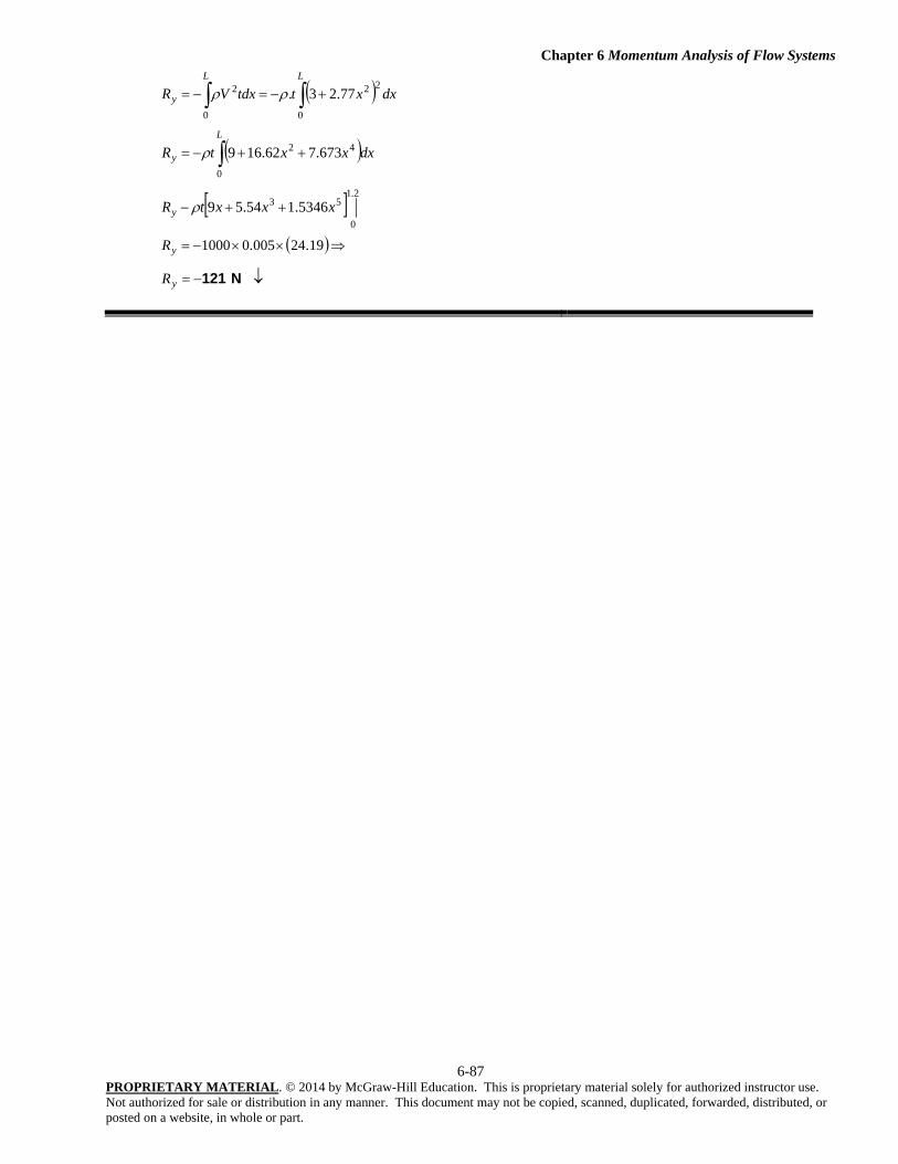
Chapter 6 Momentum Analysis of Flow Systems
PROPRIETARY MATERIAL. © 2014 by McGraw-Hill Education. This is proprietary material solely for authorized instructor use. Not authorized for sale or distribution in any manner. This document may not be copied, scanned, duplicated, forwarded, distributed, or posted on a website, in whole or part.
6-87
LL
y dxxttdxVR0
22
0
2 77.23.
L
y dxxxtR0
42 673.762.169
2.1
0
53 5346.154.59 xxxtRy
19.24005.01000yR
N 121yR
Chapter 6 Momentum Analysis of Flow Systems
PROPRIETARY MATERIAL. © 2014 by McGraw-Hill Education. This is proprietary material solely for authorized instructor use. Not authorized for sale or distribution in any manner. This document may not be copied, scanned, duplicated, forwarded, distributed, or posted on a website, in whole or part.
6-88
Fundamentals of Engineering (FE) Exam Problems
6-99
When determining the thrust developed by a jet engine, a wise choice of control volume is
(a) Fixed control volume (b) Moving control volume (c) Deforming control volume
(d) Moving or deforming control volume (e) None of these
Answer (c) Deforming control volume
6-100
Consider an airplane cruising at 850 km/h to the right. If the velocity of exhaust gases is 700 km/h to the left relative to the ground, the velocity of the exhaust gases relative to the nozzle exit is
(a) 1550 km/h (b) 850 km/h (c) 700 km/h (d) 350 km/h (e) 150 km/h
Answer (a) 1550 km/h
Solution Solved by EES Software. Solutions can be verified by copying-and-pasting the following lines on a blank EES screen. (Similar problems and their solutions can be obtained easily by modifying numerical values).
V_airplane=850 [km/h]
V_exhaust=-700 [km/h]
V_r=V_airplane-V_exhaust

Chapter 6 Momentum Analysis of Flow Systems
PROPRIETARY MATERIAL. © 2014 by McGraw-Hill Education. This is proprietary material solely for authorized instructor use. Not authorized for sale or distribution in any manner. This document may not be copied, scanned, duplicated, forwarded, distributed, or posted on a website, in whole or part.
6-89
6-101
Consider water flow through a horizontal, short garden hose at a rate of 30 kg/min. The velocity at the inlet is 1.5 m/s and that at the outlet is 14.5 m/s. Disregard the weight of the hose and water. Taking the momentum-flux correction factor to be 1.04 at both the inlet and the outlet, the anchoring force required to hold the hose in place is
(a) 2.8 N (b) 8.6 N (c) 17.5 N (d) 27.9 N (e) 43.3 N
Answer (d) 27.9 N
Solution Solved by EES Software. Solutions can be verified by copying-and-pasting the following lines on a blank EES screen. (Similar problems and their solutions can be obtained easily by modifying numerical values).
m_dot=(30/60) [kg/s]
V1=1.5 [m/s]
V2=14.5 [m/s]
beta=1.04
rho=1000 [kg/m^3]
g=9.81 [m/s^2]
A1=m_dot/(rho*V1)
P_1_gage=rho*(V2^2-V1^2)/2
A1=pi*D^2/4
F+P_1_gage*A1=m_dot*beta*(V2-V1)
6-102
Consider water flow through a horizontal, short garden hose at a rate of 30 kg/min. The velocity at the inlet is 1.5 m/s and that at the outlet is 11.5 m/s. The hose makes a 180 turn before the water is discharged. Disregard the weight of the hose and water. Taking the momentum-flux correction factor to be 1.04 at both the inlet and the outlet, the anchoring force required to hold the hose in place is
(a) 7.6 N (b) 28.4 N (c) 16.6 N (d) 34.1 N (e) 11.9 N
Answer (b) 28.4 N
Solution Solved by EES Software. Solutions can be verified by copying-and-pasting the following lines on a blank EES screen. (Similar problems and their solutions can be obtained easily by modifying numerical values).
m_dot=(30/60) [kg/s]
V1=1.5 [m/s]
V2=-11.5 [m/s]
beta=1.04
rho=1000 [kg/m^3]
g=9.81 [m/s^2]
A1=m_dot/(rho*V1)
P_1_gage=rho*(V2^2-V1^2)/2
A1=pi*D^2/4
F+P_1_gage*A1=m_dot*beta*(V2-V1)

Chapter 6 Momentum Analysis of Flow Systems
PROPRIETARY MATERIAL. © 2014 by McGraw-Hill Education. This is proprietary material solely for authorized instructor use. Not authorized for sale or distribution in any manner. This document may not be copied, scanned, duplicated, forwarded, distributed, or posted on a website, in whole or part.
6-90
6-103
A water jet strikes a stationary vertical plate horizontally at a rate of 5 kg/s with a velocity of 35 km/h. Assume the water stream moves in the vertical direction after the strike. The force needed to prevent the plate from moving horizontally is
(a) 15.5 N (b) 26.3 N (c) 19.7 N (d) 34.2 N (e) 48.6 N
Answer (e) 48.6 N
Solution Solved by EES Software. Solutions can be verified by copying-and-pasting the following lines on a blank EES screen. (Similar problems and their solutions can be obtained easily by modifying numerical values).
m_dot=5 [kg/s]
V1=35 [km/h]*Convert(km/h, m/s)
F=m_dot*V1
6-104
Consider water flow through a horizontal, short garden hose at a rate of 40 kg/min. The velocity at the inlet is 1.5 m/s and that at the outlet is 16 m/s. The hose makes a 90 turn to a vertical direction before the water is discharged. Disregard the weight of the hose and water. Taking the momentum-flux correction factor to be 1.04 at both the inlet and the outlet, the reaction force in the vertical direction required to hold the hose in place is
(a) 11.1 N (b) 10.1 N (c) 9.3 N (d) 27.2 N (e) 28.9 N
Answer (a) 11.1 N
Solution Solved by EES Software. Solutions can be verified by copying-and-pasting the following lines on a blank EES screen. (Similar problems and their solutions can be obtained easily by modifying numerical values).
m_dot=(40/60) [kg/s]
V1=1.5 [m/s]
V2=16 [m/s]
beta=1.04
F_vertical=m_dot*beta*V2

Chapter 6 Momentum Analysis of Flow Systems
PROPRIETARY MATERIAL. © 2014 by McGraw-Hill Education. This is proprietary material solely for authorized instructor use. Not authorized for sale or distribution in any manner. This document may not be copied, scanned, duplicated, forwarded, distributed, or posted on a website, in whole or part.
6-91
6-105
Consider water flow through a horizontal, short pipe at a rate of 80 kg/min. The velocity at the inlet is 1.5 m/s and that at the outlet is 16.5 m/s. The pipe makes a 90 turn to a vertical direction before the water is discharged. Disregard the weight of the pipe and water. Taking the momentum-flux correction factor to be 1.04 at both the inlet and the outlet, the reaction force in the horizontal direction required to hold the pipe in place is
(a) 73.7 N (b) 97.1 N (c) 99.2 N (d) 122 N (e) 153 N
Answer (d) 122 N
Solution Solved by EES Software. Solutions can be verified by copying-and-pasting the following lines on a blank EES screen. (Similar problems and their solutions can be obtained easily by modifying numerical values).
m_dot=(80/60) [kg/s]
V1=1.5 [m/s]
V2=16.5 [m/s]
theta_2=90 [degree]
beta=1.04
rho=1000 [kg/m^3]
g=9.81 [m/s^2]
A1=m_dot/(rho*V1)
P_1_gage=rho*(V2^2-V1^2)/2
A1=pi*D^2/4
F_horizontal+P_1_gage*A1=m_dot*beta*(V2*Cos(theta_2)-V1)
6-106
A water jet strikes a stationary vertical plate vertically at a rate of 18 kg/s with a velocity of 24 m/s. The mass of the plate is 10 kg. Assume the water stream moves in the horizontal direction after the strike. The force needed to prevent the plate from moving vertically is
(a) 192 N (b) 240 N (c) 334 N (d) 432 N (e) 530 N
Answer (c) 334 N
Solution Solved by EES Software. Solutions can be verified by copying-and-pasting the following lines on a blank EES screen. (Similar problems and their solutions can be obtained easily by modifying numerical values).
m_dot=18 [kg/s]
V1=24 [m/s]
m_plate=10 [kg]
g=9.81 [m/s^2]
F_vertical-m_plate*g=m_dot*(0-V1)

Chapter 6 Momentum Analysis of Flow Systems
PROPRIETARY MATERIAL. © 2014 by McGraw-Hill Education. This is proprietary material solely for authorized instructor use. Not authorized for sale or distribution in any manner. This document may not be copied, scanned, duplicated, forwarded, distributed, or posted on a website, in whole or part.
6-92
6-107
The velocity of wind at a wind turbine is measured to be 6 m/s. The blade span diameter is 24 m and the efficiency of the wind turbine is 29 percent. The density of air is 1.22 kg/m3. The horizontal force exerted by the wind on the supporting mast of the wind turbine is
(a) 2524 N (b) 3127 N (c) 3475 N (d) 4138 N (e) 4313 N
Answer (b) 3127 N
Solution Solved by EES Software. Solutions can be verified by copying-and-pasting the following lines on a blank EES screen. (Similar problems and their solutions can be obtained easily by modifying numerical values).
V1=6 [m/s]
D=24 [m]
eta_turbine=0.29
rho=1.22 [kg/m^3]
A=pi*D^2/4
m_dot=rho*A*V1
eta_turbine=1-KE_2/KE_1
KE_1=m_dot*V1^2/2
KE_2=m_dot*V2^2/2
F=m_dot*(V2-V1)
6-108
The velocity of wind at a wind turbine is measured to be 8 m/s. The blade span diameter is 12 m. The density of air is 1.2 kg/m3. If the horizontal force exerted by the wind on the supporting mast of the wind turbine is 1620 N, the efficiency of the wind turbine is
(a) 27.5% (b) 31.7% (c) 29.5% (d) 35.1% (e) 33.8%
Answer (e) 33.8%
Solution Solved by EES Software. Solutions can be verified by copying-and-pasting the following lines on a blank EES screen. (Similar problems and their solutions can be obtained easily by modifying numerical values).
V1=8 [m/s]
D=12 [m]
F=-1620 [N]
rho=1.2 [kg/m^3]
A=pi*D^2/4
m_dot=rho*A*V1
KE_1=m_dot*V1^2/2
F=m_dot*(V2-V1)
KE_2=m_dot*V2^2/2
eta_turbine=1-KE_2/KE_1

Chapter 6 Momentum Analysis of Flow Systems
PROPRIETARY MATERIAL. © 2014 by McGraw-Hill Education. This is proprietary material solely for authorized instructor use. Not authorized for sale or distribution in any manner. This document may not be copied, scanned, duplicated, forwarded, distributed, or posted on a website, in whole or part.
6-93
6-109
The shaft of a turbine rotates at a speed of 800 rpm. If the torque of the shaft is 350 Nm, the shaft power is
(a) 112 kW (b) 176 kW (c) 293 kW (d) 350 kW (e) 405 kW
Answer (c) 293 kW
Solution Solved by EES Software. Solutions can be verified by copying-and-pasting the following lines on a blank EES screen. (Similar problems and their solutions can be obtained easily by modifying numerical values).
n_dot=(800/60) [1/s]
M=3500 [N-m]
W_dot_shaft=2*pi*n_dot*M
6-110
A 3-cm-diameter horizontal pipe attached to a surface makes a 90 turn to a vertical upward direction before the water is discharged at a velocity of 9 m/s. The horizontal section is 5-m-long and the vertical section is 4-m long. Neglecting the mass of the water contained in the pipe, the bending moment acting on the base of the pipe on the wall is
(a) 286 Nm (b) 229 Nm (c) 207 Nm (d) 175 Nm (e) 124 Nm
Answer (a) 286 Nm
Solution Solved by EES Software. Solutions can be verified by copying-and-pasting the following lines on a blank EES screen. (Similar problems and their solutions can be obtained easily by modifying numerical values).
D=0.03 [m]
V=9 [m/s]
L_horizontal=5 [m]
L_vertical=4 [m]
rho=1000 [kg/m^3]
A=pi*D^2/4
m_dot=rho*A*V
r=L_horizontal
M=r*m_dot*V
Chapter 6 Momentum Analysis of Flow Systems
PROPRIETARY MATERIAL. © 2014 by McGraw-Hill Education. This is proprietary material solely for authorized instructor use. Not authorized for sale or distribution in any manner. This document may not be copied, scanned, duplicated, forwarded, distributed, or posted on a website, in whole or part.
6-94
6-111
A 3-cm-diameter horizontal pipe attached to a surface makes a 90 turn to a vertical upward direction before the water is discharged at a velocity of 6 m/s. The horizontal section is 5-m-long and the vertical section is 4-m long. Neglecting the mass of the pipe and considering the weight of the water contained in the pipe, the bending moment acting on the base of the pipe on the wall is
(a) 11.9 Nm (b) 46.7 Nm (c) 127 Nm (d) 104 Nm (e) 74.8 Nm
Answer (e) 74.8 Nm
Solution Solved by EES Software. Solutions can be verified by copying-and-pasting the following lines on a blank EES screen. (Similar problems and their solutions can be obtained easily by modifying numerical values).
D=0.03 [m]
V=6 [m/s]
L_horizontal=5 [m]
L_vertical=4 [m]
rho=1000 [kg/m^3]
g=9.81 [m/s^2]
A=pi*D^2/4
m_dot=rho*A*V
Vol_horizontal=pi*D^2/4*L_horizontal
m_water_horizontal=rho*Vol_horizontal
W_horizontal=m_water_horizontal*g
Vol_vertical=pi*D^2/4*L_vertical
m_water_vertical=rho*Vol_vertical
W_vertical=m_water_vertical*g
r_horizontal=L_horizontal/2
r_vertical=L_horizontal+D/2
r=L_horizontal
M-r_horizontal*W_horizontal+r_vertical*W_vertical=r*m_dot*V

Chapter 6 Momentum Analysis of Flow Systems
PROPRIETARY MATERIAL. © 2014 by McGraw-Hill Education. This is proprietary material solely for authorized instructor use. Not authorized for sale or distribution in any manner. This document may not be copied, scanned, duplicated, forwarded, distributed, or posted on a website, in whole or part.
6-95
6-112
A large lawn sprinkler with four identical arms is to be converted into a turbine to generate electric power by attaching a generator to its rotating head. Water enters the sprinkler from the base along the axis of rotation at a rate of 15 kg/s and leaves the nozzles in the tangential direction at a velocity of 50 m/s relative to the rotating nozzle. The sprinkler rotates at a rate of 400 rpm in a horizontal plane. The normal distance between the axis of rotation and the center of each nozzle is 30 cm. Estimate the electric power produced.
(a) 5430 W (b) 6288 W (c) 6634 W (d) 7056 W (e) 7875 W
Answer (d) 7056 W
Solution Solved by EES Software. Solutions can be verified by copying-and-pasting the following lines on a blank EES screen. (Similar problems and their solutions can be obtained easily by modifying numerical values).
m_dot=15 [kg/s]
V_jet_r=50 [m/s]
n_dot=(400/60) [1/s]
r=0.30 [m]
omega=2*pi*n_dot
V_nozzle=r*omega
V_jet=V_jet_r-V_nozzle
T_shaft=r*m_dot*V_jet
W_dot=2*pi*n_dot*T_shaft
6-113
Consider the impeller of a centrifugal pump with a rotational speed of 900 rpm and a flow rate of 95 kg/min. The impeller radii at the inlet and outlet are 7 cm and 16 cm, respectively. Assuming that the tangential fluid velocity is equal to the blade angular velocity both at the inlet and the exit, the power requirement of the pump is
(a) 83 W (b) 291 W (c) 409 W (d) 756 W (e) 1125 W
Answer (b) 291 W
Solution Solved by EES Software. Solutions can be verified by copying-and-pasting the following lines on a blank EES screen. (Similar problems and their solutions can be obtained easily by modifying numerical values).
n_dot=(900/60) [1/s]
m_dot=(95/60) [kg/s]
r1=0.07 [m]
r2=0.16 [m]
omega=2*pi*n_dot
T_shaft=m_dot*omega*(r2^2-r1^2)
W_dot=2*pi*n_dot*T_shaft

Chapter 6 Momentum Analysis of Flow Systems
PROPRIETARY MATERIAL. © 2014 by McGraw-Hill Education. This is proprietary material solely for authorized instructor use. Not authorized for sale or distribution in any manner. This document may not be copied, scanned, duplicated, forwarded, distributed, or posted on a website, in whole or part.
6-96
6-114
Water enters the impeller of a centrifugal pump radially at a rate of 450 L/min when the shaft is rotating at 400 rpm. The tangential component of absolute velocity of water at the exit of the 70-cm outer diameter impeller is 55 m/s. The torque applied to the impeller is
(a) 144 Nm (b) 93.6 Nm (c) 187 Nm (d) 112 Nm (e) 235 Nm
Answer (a) 144 Nm
Solution Solved by EES Software. Solutions can be verified by copying-and-pasting the following lines on a blank EES screen. (Similar problems and their solutions can be obtained easily by modifying numerical values).
V_dot=(0.450/60) [m^3/s]
n_dot=(40/60) [1/s]
D2=0.70 [m]
V_2_t=55 [m/s]
r2=D2/2
omega=2*pi*n_dot
rho=1000 [kg/m^3]
m_dot=rho*V_dot
T_shaft=m_dot*r2*V_2_t
Design and Essay Problem
6-115
Solution Students’ essays and designs should be unique and will differ from each other.