CHAPTER 6 DETERMINATION OF IN-SITU DENSITY 6.2 Sand ... · of sand is contained in the cone above...
9
Chapter 6 Standard Test Procedures Determination of In-situ Density MAY 2001 Page 6.1 CHAPTER 6 DETERMINATION OF IN-SITU DENSITY 6.1 Introduction In-situ density is widely used to control the field compaction of earthworks and pavement layers. There are a number of methods available for measuring in-situ density but only the two common methods are considered here. These are the core- cutter method and the sand replacement method. 6.2 Sand Replacement Method 6.2.1 Introduction. The sand replacement method is the most widely used in-situ density test. Although the test takes slightly longer to perform than some other in-situ density tests, the test may be carried out on most type of materials. There are various types of sand replacement equipment in use, but all types have the following essential features. a) A sand container or bottle b) A valve to start or stop the flow of sand c) A core connected to the valve and intended to fit over the area being tested. d) A base plate which acts as a template during the excavation of the soil. The stated size of the pouring cylinder relates to the diameter of the cone and thus the diameter of the hole to be excavated. The three sizes commonly available are 100 mm, 150 mm and 200 mm. The 100mm apparatus is mainly used for fine grained soils as used for earthworks and the 200mm apparatus is intended for coarse grained materials as used in the sub-base and base layers. 6.2.2 Apparatus. The following apparatus is required for the test : a) A pouring cylinder (Small or Large) (see Figure 6.2.1.) b) Suitable tools for excavating holes in compacted soil (bent spoon, scraper tool, hammers, chisels and paint brush) c) Cylindrical metal calibrating container with an internal diameter of 200±5 mm and internal depth of 250 mm fitted with a lip about 75 mm wide and about 5 mm thick surrounding the open end for large pouring cylinder and internal diameter 100±2 mm and internal depth of 150±3 mm fitted with a lip about 50 mm wide and about 5 mm thick is required (see Figure 6.2.2). d) Balance, readable to 10g for the large pouring cylinder method, or readable to 1 g for the small pouring cylinder method. e) Glass plate of 10mm thick and about 500mm square. f) Metal trays or containers g) Apparatus for moisture content determination h) A metal tray about 500mm square and about 50mm deep with a 200mm diameter hole in the centre for large pouring cylinder and about 300mm square and about 40mm deep with a 100mm diameter hole in the centre. i) Clean closely graded, preferably with rounded grains replacement sand. (100% passing 600μm sieve and 100% retained on the 75μm sieve).
Transcript of CHAPTER 6 DETERMINATION OF IN-SITU DENSITY 6.2 Sand ... · of sand is contained in the cone above...

Chapter 6 Standard Test ProceduresDetermination of In-situ Density
MAY 2001 Page 6.1
CHAPTER 6
DETERMINATION OF IN-SITU DENSITY
6.1 Introduction
In-situ density is widely used to control the field compaction of earthworks andpavement layers. There are a number of methods available for measuring in-situdensity but only the two common methods are considered here. These are the core-cutter method and the sand replacement method.
6.2 Sand Replacement Method
6.2.1 Introduction. The sand replacement method is the most widely used in-situ densitytest. Although the test takes slightly longer to perform than some other in-situ densitytests, the test may be carried out on most type of materials.
There are various types of sand replacement equipment in use, but all types havethe following essential features.
a) A sand container or bottleb) A valve to start or stop the flow of sandc) A core connected to the valve and intended to fit over the area being tested.d) A base plate which acts as a template during the excavation of the soil.
The stated size of the pouring cylinder relates to the diameter of the cone and thusthe diameter of the hole to be excavated. The three sizes commonly available are100 mm, 150 mm and 200 mm. The 100mm apparatus is mainly used for fine grainedsoils as used for earthworks and the 200mm apparatus is intended for coarsegrained materials as used in the sub-base and base layers.
6.2.2 Apparatus. The following apparatus is required for the test :
a) A pouring cylinder (Small or Large) (see Figure 6.2.1.)b) Suitable tools for excavating holes in compacted soil (bent spoon, scraper tool,
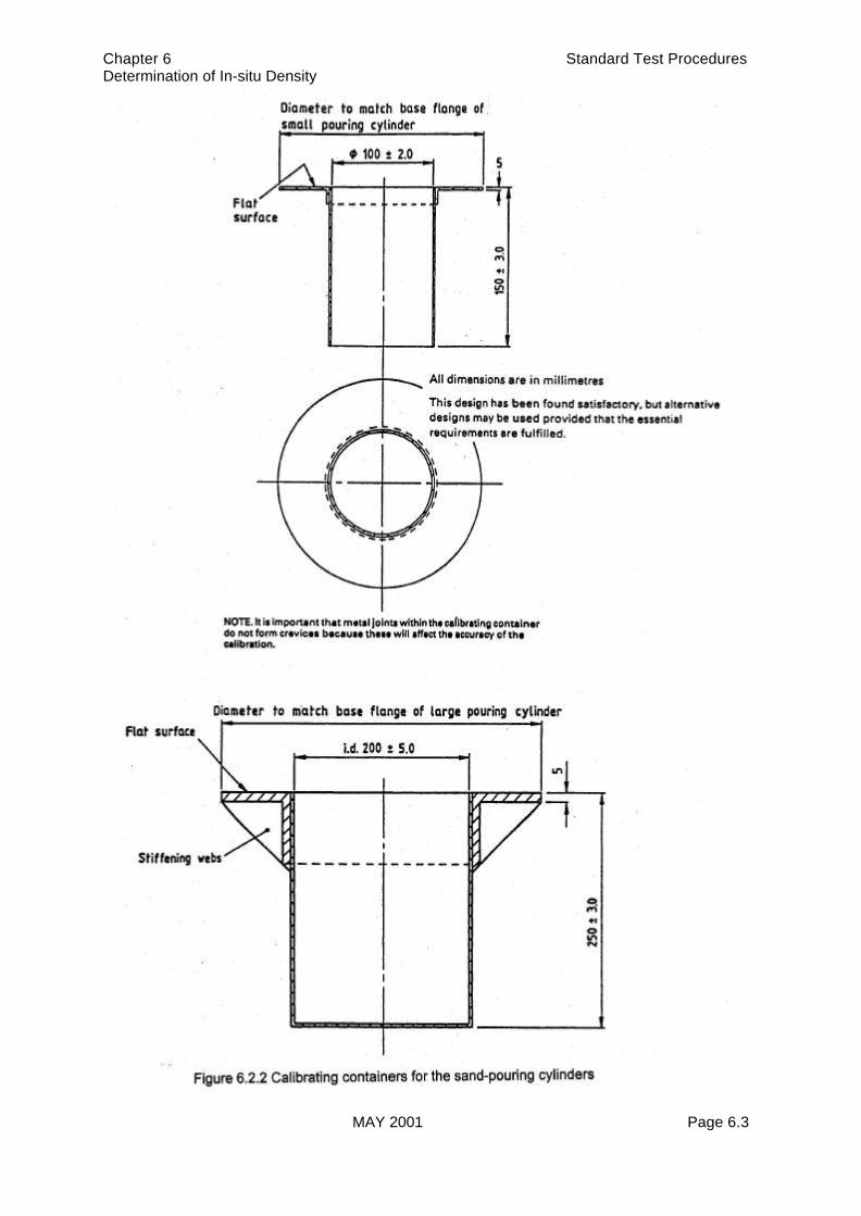
hammers, chisels and paint brush)c) Cylindrical metal calibrating container with an internal diameter of 200±5 mm and
internal depth of 250 mm fitted with a lip about 75 mm wide and about 5 mm thicksurrounding the open end for large pouring cylinder and internal diameter 100±2mm and internal depth of 150±3 mm fitted with a lip about 50 mm wide and about5 mm thick is required (see Figure 6.2.2).
d) Balance, readable to 10g for the large pouring cylinder method, or readable to 1g for the small pouring cylinder method.
e) Glass plate of 10mm thick and about 500mm square.f) Metal trays or containersg) Apparatus for moisture content determinationh) A metal tray about 500mm square and about 50mm deep with a 200mm diameter
hole in the centre for large pouring cylinder and about 300mm square and about40mm deep with a 100mm diameter hole in the centre.
i) Clean closely graded, preferably with rounded grains replacement sand. (100%passing 600µm sieve and 100% retained on the 75µm sieve).

Chapter 6 Standard Test ProceduresDetermination of In-situ Density
MAY 2001 Page 6.2
Chapter 6 Standard Test ProceduresDetermination of In-situ Density
MAY 2001 Page 6.3

Chapter 6 Standard Test ProceduresDetermination of In-situ Density
MAY 2001 Page 6.4
6.2.3 Calibrations
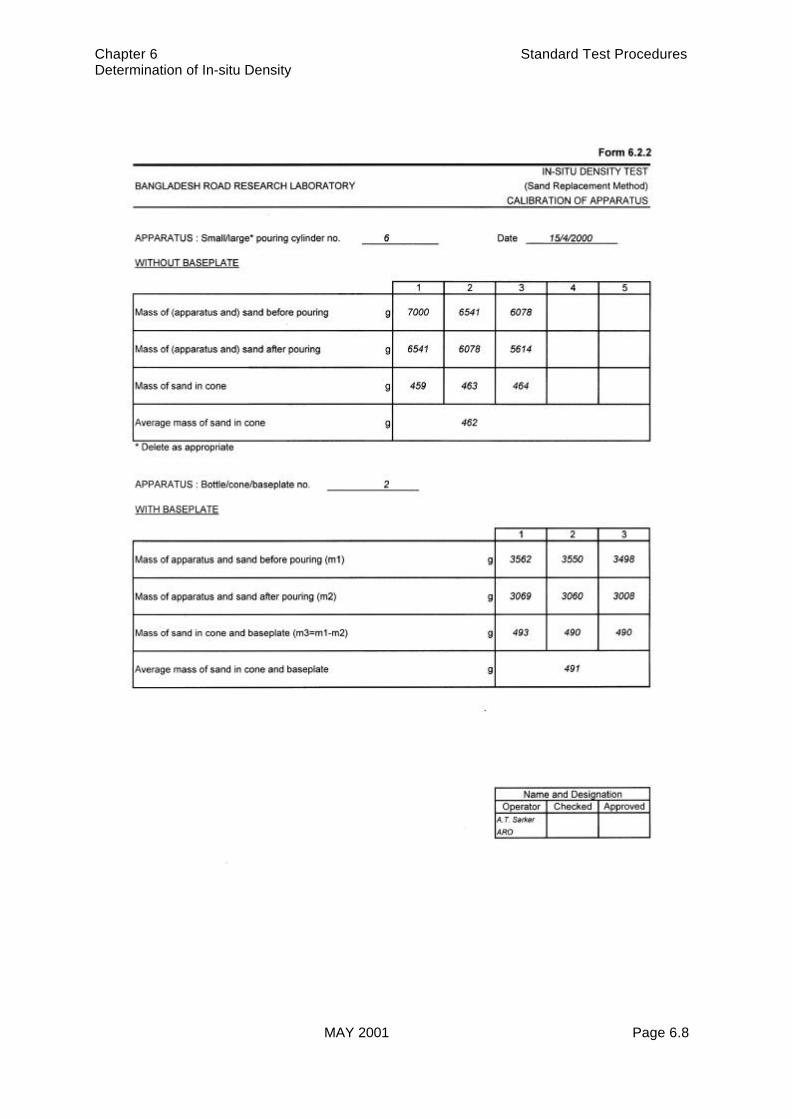
6.2.3.1 Calibration of apparatus. When the apparatus is used for a test a certain amountof sand is contained in the cone above the excavated hole. This weight of sand mustbe deducted from the total weight of sand used in the test in order to determine theexact weight of sand used to fill the hole. The apparatus must then be calibrated todetermine the weight of sand in the cone. As the weight of sand in the cone will varyslightly with the type of sand used, calibration of the apparatus should take placeeach time the sand is calibrated.
One minor complication is that generally the base-plate is left in place during the testand a small amount of sand is retained between the base-plate and the cone. In thiscase, the calibration of the apparatus should be carried out using both base-plateand cone. It is not normal to use the base-plate when calibrating the sand so, in thiscase, the calibration of the apparatus should be done with the cone only.
To calibrate the apparatus, it is partly filled with sand and weighed. The apparatus(with base-plate if required) is then placed on a flat glass plate and the valve isopened. When the cone is completely full of sand, the valve is closed and theapparatus is re-weighed. The difference between the two weights is the weight ofsand in the cone and base-plate if used. The calibration is normally repeated threetimes and the average value taken.
6.2.3.2 Calibration of sand. The sand should be stored in a clean container and protectedfrom rain and damp and should be airtight. The purpose of the calibration is todetermine the density of the sand being used. Each new batch of sand should becalibrated before use and existing sand should be calibrated weekly or monthlydepending on the frequency of use. The calibrating container is of the same diameteras the apparatus being used and has a depth similar to that of the hole excavated forthe test. To use the container, fill the apparatus first with sand and weigh it. Thenplace the cone over the calibration container and open the valve to allow the sand tofill the cone and the container. When the cone is completely full close the valve andreweigh the apparatus. The difference between these two weights is the weight ofsand in the container plus the weight of sand in the cone. The weight of sand in thecone is found from the calibration of apparatus and may be deducted from the totalweight of sand to give the weight of sand in the container. The container is thenemptied, weighed and then filled with clean water. Wipe off any surplus water on thesides of the containers with a clean cloth and reweigh the container plus water. Theweight of water in the container and thus its volume are then determined. Repeatthese measurements at least three times and calculate the mean values.
6.2.4. Excavation of test hole
6.2.4.1 Preparation of surface. Expose a flat area, approximately 600mm square(approximately 450mm square for the small cylinder method) of the soil to be testedand trim it down to a level surface. Brush away any loose material which is not part ofthat being tested. The surface should be as level as possible in order to reproducethe laboratory calibration conditions.
6.2.4.2 Excavation procedure
1) Lay the metal tray on the prepared surface with the hole over the portion of thesoil to be tested. Run a trowel or other sharp tool around the outside of the tray,marking square on the surface of the soil being tested. This will help to positionthe pouring cylinder during the later stages of the test. It is often helpful for thetray to be nailed to the ground to stop it moving during the excavation of the testhole.

Chapter 6 Standard Test ProceduresDetermination of In-situ Density
MAY 2001 Page 6.5
2) Using the hole in the metal tray as a pattern, excavated a round hole,approximately 200 mm in diameter (100 mm for the small cylinder method) andthe depth of the layer to be tested up to a maximum of 250 mm deep (150 mm forthe small cylinder method). Do not leave loose material in the hole and do notdistort the immediate surround to the hole. Carefully collect all the excavated soilfrom the hole and determine its mass, mw to the nearest 10g (1 g for the smallcylinder method). Remove the metal tray before placing the pouring cylinder inposition over the excavated hole.
Note. Take care in excavating the hole to see that the hole is not enlarged bylevering the excavating tool against the side of the hole, as this willresult in lower densities being recorded.
3) Place a representative sample of the excavated soil in an airtight container anddetermine its moisture content, w. Alternatively, the whole of the excavated soilshall be dried and its mass md, determined.
4) Place the pouring cylinder filled with the constant mass of sand (m1) so that thebase of the cylinder covers the hole concentrically. This is assisted by the squarepreviously marked around the tray. Keep the shutter on the pouring cylinderclosed during this operation. Open the shutter and allow sand to run out; duringthis period do not vibrate the pouring cylinder or the surrounding area. When nofurther movement of the sand takes place, close the shutter. Remove the cylinderand determine the mass of sand remaining in it (m4) to the nearest 10 g (nearest1 g for the small cylinder method). For the small cylinder method this is easilydone by weighing the cylinder and remaining sand together.
6.2.5 Calculation and expression of results
6.2.5.1 Calculations
1) Calculate the mass of sand required to fill the calibrating container, ma (in g),from the equation:
ma = m1 - m3 - m2
wherem1 is the mass of [cylinder and] sand before pouring in the calibrating container(in g) :m2 is the mean mass of sand in cone (in g);m3 is the mean mass of [cylinder and] sand after pouring into the calibratingcontainer (in g).
2) Calculate the bulk density of the sand. ρa (in Mg/m3), from the equation :
ρa = ma
V
where, V is the volume of the calibrating container (in mL).
ρ

Chapter 6 Standard Test ProceduresDetermination of In-situ Density
MAY 2001 Page 6.6
3) Calculate the mass of sand required to fill the excavated hole, mb (in g). from theequation:
mb = m1 - m4 - m2
where,m1 is the mass of [cylinder and] sand before pouring in the hole (in g) :m2 is the mean mass of sand in the cone (in g);m4 is the mean mass of [cylinder and] sand after pouring into the hole (in g)
4) Calculate the bulk density of the soil. ρ (in mg/m3). from the equation:
ρ ρ = mm
w
ba
wheremw is the mass of soil excavated (in g);mb is the mean mass of sand required to fill the hole (in g);ρa is the bulk density of the sand (in Mg/m3).
5) Calculate the dry density, ρd (in Mg/m3), from the equation:
w+100100
= ρ
ρd
where, w is the moisture content of the soil (in %).
6) Calculate the in-situ relative compaction (RC) of the tested layer from theequation :
%100 MDD
= RC d xρ
where,MDD is the Maximum Dry Density obtained from the compaction test used as thestandard for the particular layer. Note that the type of compaction test used isdependent on the type of material.
Example of completed calculations are shown in Forms 6.2.1 to 6.2.3.
6.2.6 Report. The correct test form must be used for the report. The report shall containthe following information:
a) The in-situ bulk and dry densities of the soil (in Mg/m3) to the nearest 0.01 inMg/m3.
b) The moisture content. as a percentage, to two significant figures.c) All other information required by the test form. e.g. sample origin, description etc.d) The operator should sign and date the test form.

Chapter 6 Standard Test ProceduresDetermination of In-situ Density
MAY 2001 Page 6.7
Chapter 6 Standard Test ProceduresDetermination of In-situ Density
MAY 2001 Page 6.8

Chapter 6 Standard Test ProceduresDetermination of In-situ Density
MAY 2001 Page 6.9


![4,800 122,000 135Mproppants can be classified into three types which are silica sand, resin coated sand, and ceramic proppant [15]. The utilization of proppant must be appropriate](https://static.fdocuments.net/doc/165x107/60ed6d59d8db833613323554/4800-122000-135m-proppants-can-be-classified-into-three-types-which-are-silica.jpg)