Chapter 6: Cross-Sectional Properties of Structural Members Chap06 - Cross Section...
13
6.1 Chapter 6: Cross-Sectional Properties of Structural Members Introduction Beam design requires the knowledge of the following. • Material strengths (allowable stresses) • Critical shear and moment values • Cross sectional properties The shape and proportion of a beam cross section is critical in keeping bending and shear stresses within allowable limits and limiting the deflection that will result from the loads. 1. Why does a 2” x 8” joist standing on edge deflect less when loaded at mid span than the same 2” x 8” used as a plank? 2. Columns with improperly configured cross sections may be highly susceptible to buckling under relatively moderate loads. 3. Are circular pipe columns better at supporting axial loads than columns with a cruciform cross section? It will be necessary to calculate two cross-sectional properties crucial to the design of beams and columns: the centroid and the moment of inertia. 6.1 Center of Gravity - Centroids Center of gravity (CG) (or center of mass) refers to masses or weights. • The center of gravity of a mass or an area is the theoretical point at which the entire mass or area is considered to be concentrated (a.k.a. “balance point”). • If an object were homogeneous, the center of gravity and centroid would coincide. - Consider a composite made of Styrofoam and lead. Center of gravity Centroid
Transcript of Chapter 6: Cross-Sectional Properties of Structural Members Chap06 - Cross Section...

6.1
Chapter 6: Cross-Sectional Properties of Structural Members
Introduction
Beam design requires the knowledge of the following.
• Material strengths (allowable stresses)
• Critical shear and moment values
• Cross sectional properties
The shape and proportion of a beam cross section is critical in keeping bending and
shear stresses within allowable limits and limiting the deflection that will result
from the loads.
1. Why does a 2” x 8” joist standing on edge deflect less when loaded at mid span
than the same 2” x 8” used as a plank?
2. Columns with improperly configured cross sections may be highly susceptible to
buckling under relatively moderate loads.
3. Are circular pipe columns better at supporting axial loads than columns with a
cruciform cross section?
It will be necessary to calculate two cross-sectional properties crucial to the
design of beams and columns: the centroid and the moment of inertia.
6.1 Center of Gravity - Centroids
Center of gravity (CG) (or center of mass) refers to masses or weights.
• The center of gravity of a mass or an area is the theoretical point at which the
entire mass or area is considered to be concentrated (a.k.a. “balance point”).
• If an object were homogeneous, the center of gravity and centroid would
coincide.
- Consider a composite made of Styrofoam and lead.
Center of gravity Centroid

6.2
The centroid is a geometric property of the volume or area.
• If densities vary, the center of gravity and centroid do not coincide.
• Centroid usually refers to the centers of lines, areas, and volumes.
• The centroid of cross-sectional areas (of beams and columns) will be used later
as the reference origin for computing other section properties.
The method of locating the center of gravity is based on the method of
determining the resultants of parallel force systems and the principle of moments.
• An area is divided into a number of small areas.
• Each area is represented by a weight acting at its centroid.
• The resultant of the entire area would act through the center of gravity of the
total area.
Consider the plate shown at the right.
• The plate is divided into small
increments (called components).
• Each component has its own weight
and centroid, with all weights
directed perpendicular to the
surface area (x-y plane).
• The summation of these forces adds up to the total weight of the plate.
∑Fz : W = ΔW1 + ΔW2 + ΔW3 + • • • + ΔWn
The centroid is obtained by taking
moments about the x and y-axes,
respectively.
∑My : x W = ΔW1 x1 + ΔW2 x2 + ΔW3 x3 + • • • + ΔWn xn
∑Mx : y W = ΔW1 y1 + ΔW2 y2 + ΔW3 y3 + • • • + ΔWn yn
x = ∑(x ΔW)/W y = ∑(y ΔW)/W

6.3
If the plate is divided into an infinite number of elemental pieces, the centroidal
expressions may be rewritten in calculus form as follows.
W = ∫ dW x = ∫ x dW/W y = ∫ y dW/W
Assuming that the plate is of uniform thickness and density, the total weight can
be expressed as follows.
W = γ t A
where
W = total weight of the plate
γ = density of the plate material
t = plate thickness
A = surface area of the plate
Correspondingly, for the component parts (areas) of the plate with uniform
thickness, the weight of each part may be expressed as follows.
ΔW = γ t ΔA
where
ΔW = weight of component plate area
ΔA = surface area of component
If we return to the moment equations written above and substitute the values “γ t
A” for “W” and “γ t ΔA” for “ΔW,” we find that, if the plate is homogeneous and of
constant thickness, “γ t” cancels out of the equations.
• The resulting moment equations would then be written as follows.
∑My : x A = ΔA1 x1 + ΔA2 x2 + ΔA3 x3 + • • • + ΔAn xn
∑Mx : y A = ΔA1 y1 + ΔA2 y2 + ΔA3 y3 + • • • + ΔAn yn
x = ∑(x ΔA)/A y = ∑(y ΔA)/A
where
A = ∑ΔA
The coordinates x and y define the centroid for the area.

6.4
The centroids of some of the more common areas have been derived and are shown
in Table 6.1 (p. 304) of the text.
To find the centroid of a more complex area (i.e. a composite area), the following
procedure may be used.
• The area is first divided into simpler geometric shapes with known centroid
locations.
• A reference origin is chosen to establish the reference x- and y-axes.
• The moments of area are summed about the reference x- and y-axes,
respectively.
• A tabular solution is often a convenient way to determine the location of the
centroid for a composite area.
Symmetry
• When an area (e.g. rectangle, circle, or half-circle) or line possesses an axis of
symmetry (i.e. a mirror image on either side of the axis) the centroid of the
area must be located on that axis.
• If an area or line possesses two axes of symmetry, the centroid of the area is
located at the intersection of the two axes of symmetry.

6.5
Example Problem - Centroids
Given: The area shown.
Find: Location of the centroid (x , y ).
Solution
Part Area, Ai x i y i x i Ai y i Ai
1 10,800 45.0 120.0 486,000 1,296,000
2 2,700 30.0 40.0 81,000 108,000
3 - 2,510 73.0 120.0 - 183,000 - 301,000
Totals 10,990 384,000 1,103,000
A3 = π r2/2 = π (40)2/2 = 2,510
x3 = 90 – 4r/3 π = 90 – 4(40)/3π = 73.0
x = Σx i Ai/ΣAi = 384,000/10,990
x = 34.9 mm
y = Σ y i Ai/ΣAi = 1,103,000/10,990
y = 100.4 mm

6.6
Given: The cover-plated beam shown.
Find: Neutral axis.
The “neutral axis” is an axis in the cross
section of a beam (a member resisting
bending) along which there are no
longitudinal stresses or strains.
• If the section is symmetric, then the
neutral axis is located at the geometric
centroid.
A vertical axis through the center of the web forms an axis of symmetry.
• Only the y distance is required.
Use the bottom of the bottom flange as the reference axis.
y = Σ y i Ai/ΣAi = [22.3 (18.2/2) + 1(12)(18.2 + 1.0/2)]/[22.3 + 1(12)]
= (202.93 + 224.40)/34.3
y = 12.46”
6.7
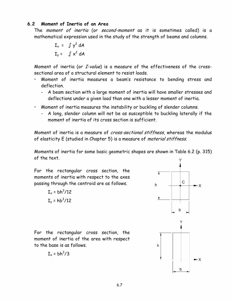
6.2 Moment of Inertia of an Area
The moment of inertia (or second-moment as it is sometimes called) is a
mathematical expression used in the study of the strength of beams and columns.
Ix = ∫ y2 dA
Iy = ∫ x2 dA
Moment of inertia (or I-value) is a measure of the effectiveness of the cross-
sectional area of a structural element to resist loads.
• Moment of inertia measures a beam’s resistance to bending stress and
deflection.
- A beam section with a large moment of inertia will have smaller stresses and
deflections under a given load than one with a lesser moment of inertia.
• Moment of inertia measures the instability or buckling of slender columns.
- A long, slender column will not be as susceptible to buckling laterally if the
moment of inertia of its cross section is sufficient.
Moment of inertia is a measure of cross-sectional stiffness, whereas the modulus
of elasticity E (studied in Chapter 5) is a measure of material stiffness.
Moments of inertia for some basic geometric shapes are shown in Table 6.2 (p. 315)
of the text.
For the rectangular cross section, the
moments of inertia with respect to the axes
passing through the centroid are as follows.
Ix = bh3/12
Iy = hb3/12
For the rectangular cross section, the
moment of inertia of the area with respect
to the base is as follows.
Ix = bh3/3
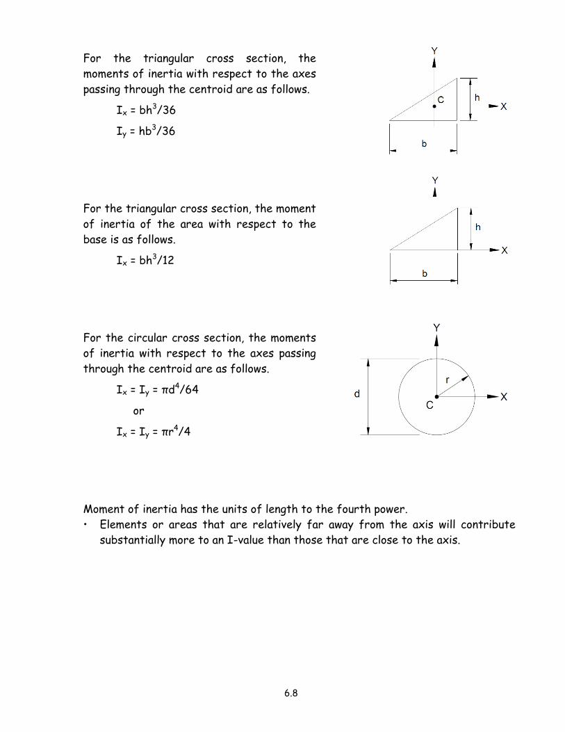
6.8
For the triangular cross section, the
moments of inertia with respect to the axes
passing through the centroid are as follows.
Ix = bh3/36
Iy = hb3/36
For the triangular cross section, the moment
of inertia of the area with respect to the
base is as follows.
Ix = bh3/12
For the circular cross section, the moments
of inertia with respect to the axes passing
through the centroid are as follows.
Ix = Iy = πd4/64
or
Ix = Iy = πr4/4
Moment of inertia has the units of length to the fourth power.
• Elements or areas that are relatively far away from the axis will contribute
substantially more to an I-value than those that are close to the axis.

6.9
6.3 Moment of Inertia of Composite Areas
In steel and concrete construction, the cross-sections usually used for beams and
columns are not the simple geometric shapes that are shown in Table 6.2.
• Most structural shapes (e.g. a W-shape) are a composite of two or more simple
shapes combined into configurations that produce structural efficiency.
• These shapes are called composite areas.
In structural design, the moment of inertia about the centroidal axis of the cross
section is an important section property.
The parallel axis theorem provides a simple way to compute the moment of inertia
of a shape about any axis that is parallel to the centroidal axis of the area.
• The principle of the parallel axis theorem may be stated as follows.
“The moment of inertia of an area with respect to any axis not through its centroid is equal to the moment of inertia of that area with respect to its own parallel centroidal axis plus the product of the area and the square of the distance between the two axes.”
For a single area, the parallel axis theorem with respect to the x-axis can be
expressed in the following equation form.
Ix = Ixc + A dy2
where
Ix = moment of inertia of the area
about the x-axis
Ixc = moment of inertia of the area
about its own centroidal x-axis
A = area
dy = the perpendicular distance
between the x-axis and the
parallel axis that passes
through the centroid of the
area
Similarly, for a single area, the parallel axis theorem with respect to the y-axis can
be expressed in the following equation form.
Iy = Iyc + A dx2

6.10
For composite areas, the parallel axis theorem with respect to the x–axis can be
expressed as follows.
Ix = Ixc1 + A1 (dy1)2 + Ixc2 + A2 (dy2)
2 + • • •
= [Ixc1 + Ixc2 + • • •] + [A1 (dy1)2 + A2 (dy2)
2 + • • •]
Ix = ∑ Ixc + ∑A dy2
Similarly, for composite areas, the parallel axis theorem with respect to the y-axis
can be expressed as follows.
Iy = Iyc1 + A1 (dx1)2 + Iyc2 + A2 (dx2)
2 + • • •
= [Iyc1 + Iyc2 + • • •] + [A1 (dx1)2 + A2 (dx2)
2 + • • •]
Iy = ∑ Iyc + ∑A dx2
A tabular solution is often a convenient way to determine the moment of inertia
for a composite area.

6.11
Example Problems - Moment of Inertia of Composite Areas
Given: The composite area shown.
Find: Ix and Iy
Part Ai x i y i Ai x i Ai y i Ai x i2 Ai y i
2 I xi I yi
1 27.00 - 1.50 1.50 - 40.50 40.50 60.75 60.75 182.25 20.25
2 27.00 - 5.00 0 - 135.00 0 675.00 0 121.50 54.00
3 28.27 2.55 2.55 72.09 72.09 183.83 183.83 71.15 71.15
4 - 6.28 - 3.00 - 0.85 18.84 5.34 - 56.52 - 4.54 - 1.74 - 6.28
75.99 - 84.57 117.93 863.06 240.04 373.16 139.12
x 3 = 4R/3π = 4(6)/3π = 2.55 = y 3 y 4 = - 4R/3π = - 4(2)/3π = - 0.85
I x1 = bh3/12 = 3(9)3/12 = 182.25 I y1 = bh3/12 = 9(3)3/12 = 20.25
I x2 = bh3/36 = 6(9)3/36 = 121.50 I y2 = bh3/36 = 9(6)3/36 = 54.00
I x3 = 0.0549R4 = 0.0549(6)4 = 71.15 I y3 = I x3 = 71.15
I x4 = 0.109R4 = 0.109(2)4 = 1.74 I y4 = (π/8)R4 = (π/8)(2)4 = 6.28
Use I x4 = - 1.74 (negative area) Use I y4 = - 6.28 (negative area)
• The moments of inertia with respect to the x- and y-axes are determined as
follow.
Ix = ∑ I xi + ∑ y i2Ai = 373.16 + 240.04 = 613.20 in4
Iy = ∑ I yi + ∑ x i2Ai = 139.12 + 863.06 = 1002.18 in4
• The location of the centroid is determined as follows.
x = ∑x iAi/∑Ai = - 84.57/75.99 = - 1.11”
y = ∑ y iAi/∑Ai = 117.93/75.99 = 1.55”
• The centroidal moments of inertia for the composite area are determined as
follows.
I x = Ix – y 2A = 613.20 – (1.55)2 75.99 = 430.63 in4
I y = Iy – x2A = 1002.18 – (- 1.11)2 75.99 = 908.55 in4

6.12
Given: The cover-plated beam shown.
Find: The moment of inertia with respect to
a horizontal axis through the centroid of
the area (i.e. the neutral axis).
A vertical axis through the center of the
web forms an axis of symmetry.
• Only the y distance is required.
Find the location of the centroid (which corresponds with the neutral axis).
• Use the bottom of the bottom flange as the reference axis.
y = Σ y i Ai/ΣAi = 31.7 (29.8/2) + 1(18)(29.8 + 1.0/2)
31.7 + 1(18)
= 472.33 + 545.40
49.7
y = 20.48”
Using the “Parallel Axis Theorem”,
determine the moment of inertia with
respect to a horizontal axis through the
centroid of the area (i.e. the neutral axis).
Ix = (Ix)beam + (Ix)plate
= [4470 + 31.7(29.8/2 – 20.48)2] + [18(1)3/12 + 1(18)(29.8 + 1.0/2 – 20.48)2]
= (4470 + 987.02) + (1.50 + 1735.78)
Ix = 7194.30 in4

6.13
6.4 Radius of Gyration
In the study of columns (Chapter 9) we will be using a section property known as
the radius of gyration.
• The radius of gyration (designated as “rx” or “ry”) expresses the relationship
between the area of a cross section and the moment of inertia.
• The radius of gyration is a shape factor that measures a column’s resistance to
buckling about an axis.
• The larger the r-value, the more resistance there is to buckling.
Consider an area A that has a moment of
inertia Ix with respect to the x-axis.
• Let the area is concentrated into a thin
strip parallel to the x-axis.
• The area has the same moment of inertia
as the original area.
• The strip is placed at a distance rx from
the axis.
Then Ix = A rx2
rx2 = Ix/A
and rx = (Ix/A)1/2
Similarly, Iy = A ry2
ry2 = Iy/A
and ry = (Iy/A)1/2