Chapter 4 Network Layer - UNSW School of Computer...
133
Network Layer 4-1 Chapter 4 Network Layer Computer Networking: A Top Down Approach 4 th edition. Jim Kurose, Keith Ross Addison-Wesley, July 2007. A note on the use of these ppt slides: The notes used in this course are substantially based on powerpoint slides developed and copyrighted by J.F. Kurose and K.W. Ross, 1996- 2007
Transcript of Chapter 4 Network Layer - UNSW School of Computer...

Network Layer 4-1
Chapter 4Network Layer
Computer Networking: A Top Down Approach 4th edition. Jim Kurose, Keith RossAddison-Wesley, July 2007.
A note on the use of these ppt slides:The notes used in this course are substantially based on powerpoint slides developed and copyrighted by J.F. Kurose and K.W. Ross, 1996-2007

Network Layer 4-2
Chapter 4: Network Layer
Chapter goals:Understand principles behind network layer services:
Network layer service modelsForwarding versus routingHow a router worksRouting (path selection)Dealing with scaleAdvanced topics: IPv6, mobility
Instantiation, implementation in the Internet
Network Layer 4-3
Chapter 4: Network Layer
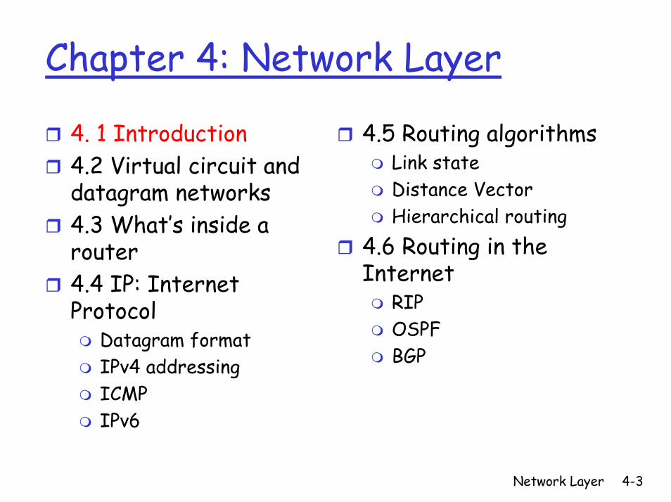
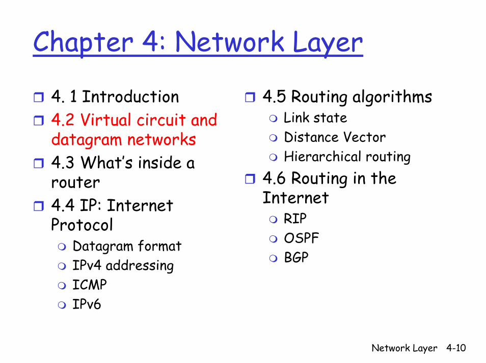
4. 1 Introduction4.2 Virtual circuit and datagram networks4.3 What’s inside a router4.4 IP: Internet Protocol
Datagram formatIPv4 addressingICMPIPv6
4.5 Routing algorithmsLink stateDistance VectorHierarchical routing
4.6 Routing in the Internet
RIPOSPFBGP
Network Layer 4-4
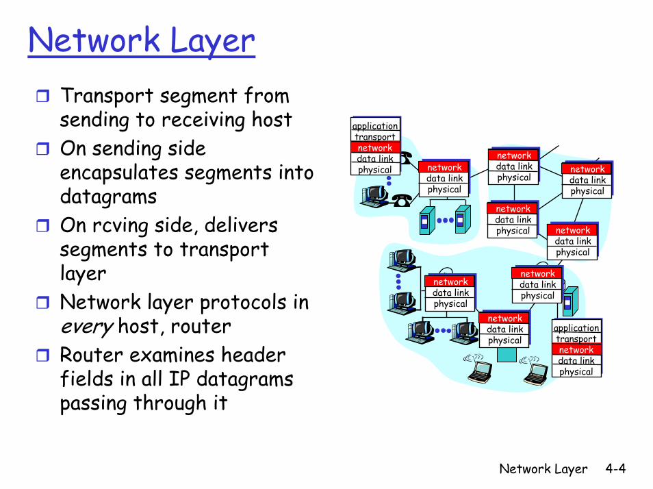
Network LayerTransport segment from sending to receiving host On sending side encapsulates segments into datagramsOn rcving side, delivers segments to transport layerNetwork layer protocols in every host, routerRouter examines header fields in all IP datagrams passing through it
networkdata linkphysical
networkdata linkphysical
networkdata linkphysical
networkdata linkphysical
networkdata linkphysical
networkdata linkphysical
networkdata linkphysical
networkdata linkphysical
applicationtransportnetworkdata linkphysical
applicationtransportnetworkdata linkphysical

Network Layer 4-5
Two Key Network-Layer Functions
Forwarding: move packets from router’s input to appropriate router output
Routing: determine route taken by packets from source to dest
Routing algorithms
Analogy:
Routing: process of planning trip from source to destForwarding: process of getting through single interchange
Network Layer 4-6
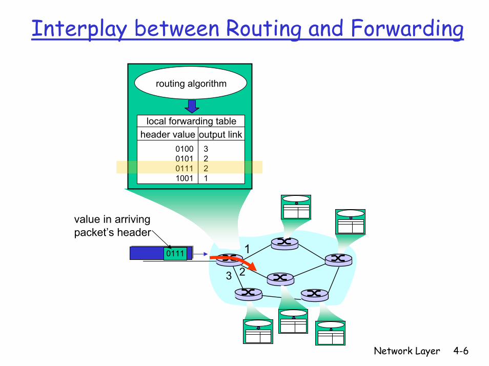
Interplay between Routing and Forwarding
1
23
0111
value in arrivingpacket’s header
routing algorithm
local forwarding tableheader value output link
0100010101111001
3221

Network Layer 4-7
Connection Setup
The 3rd important function in some network architectures:
ATM, frame relay, X.25Before datagrams flow, two end hosts and intervening routers establish virtual connection
Routers get involvedNetwork vs. transport layer connection service:
Network: between two hosts (may also involve intervening routers in case of VCs)Transport: between two processes
Network Layer 4-8
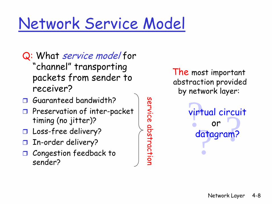
Network Service Model
Q: What service model for “channel” transporting packets from sender to receiver?Guaranteed bandwidth?Preservation of inter-packet timing (no jitter)?Loss-free delivery?In-order delivery?Congestion feedback to sender?
service abstraction? ??virtual circuit
or datagram?
The most importantabstraction provided
by network layer:
Network Layer 4-9
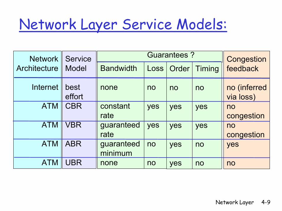
Network Layer Service Models:
Order
no
yes
yes
yes
yes
Timing
no
yes
yes
no
no
Congestionfeedback
no (inferredvia loss)nocongestionnocongestionyes
no
Loss
no
yes
yes
no
no
NetworkArchitecture
Internet
ATM
ATM
ATM
ATM
ServiceModel
best effortCBR
VBR
ABR
UBR
Bandwidth
none
constantrateguaranteedrateguaranteed minimumnone
Guarantees ?
Network Layer 4-10
Chapter 4: Network Layer
4. 1 Introduction4.2 Virtual circuit and datagram networks4.3 What’s inside a router4.4 IP: Internet Protocol
Datagram formatIPv4 addressingICMPIPv6
4.5 Routing algorithmsLink stateDistance VectorHierarchical routing
4.6 Routing in the Internet
RIPOSPFBGP
Network Layer 4-11
Network Layer Connection and Connection-less Service
Datagram network provides network-layer connectionless serviceVC network provides network-layer connection serviceAnalogous to the transport-layer services, but:
Service: host-to-hostNo choice: network provides one or the otherImplementation: in network core
Network Layer 4-12
Virtual Circuits
“source-to-dest path behaves much like telephone circuit”
Performance-wiseNetwork actions along source-to-dest path
Call setup, teardown for each call before data can flowEach packet carries VC identifier (not destination host address)Every router on source-dest path maintains “state” for each passing connectionLink, router resources (bandwidth, buffers) may be allocated to VC (dedicated resources = predictable service)
Network Layer 4-13
VC Implementation
A VC consists of:1. Path from source to destination2. VC numbers, one number for each link along
path3. Entries in forwarding tables in routers along
pathPacket belonging to VC carries VC number (rather than dest. address)VC number can be changed on each link
New VC number comes from forwarding table
Network Layer 4-14
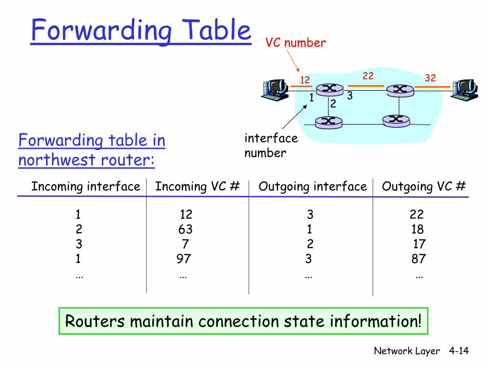
Forwarding Table12 22 32
1 23
VC number
interfacenumber
Forwarding table innorthwest router:
Incoming interface Incoming VC # Outgoing interface Outgoing VC #
1 12 3 222 63 1 18 3 7 2 171 97 3 87… … … …
Routers maintain connection state information!
Network Layer 4-15
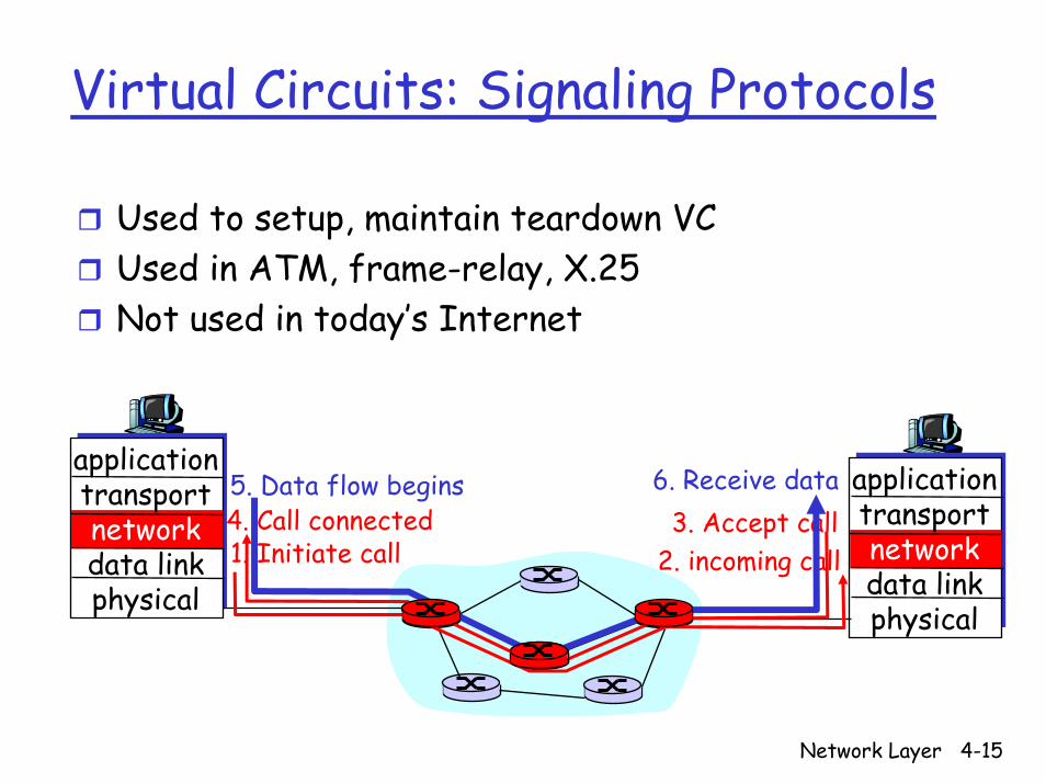
Virtual Circuits: Signaling Protocols
Used to setup, maintain teardown VCUsed in ATM, frame-relay, X.25Not used in today’s Internet
applicationtransportnetworkdata linkphysical
applicationtransportnetworkdata linkphysical
1. Initiate call 2. incoming call3. Accept call4. Call connected
5. Data flow begins 6. Receive data
Network Layer 4-16
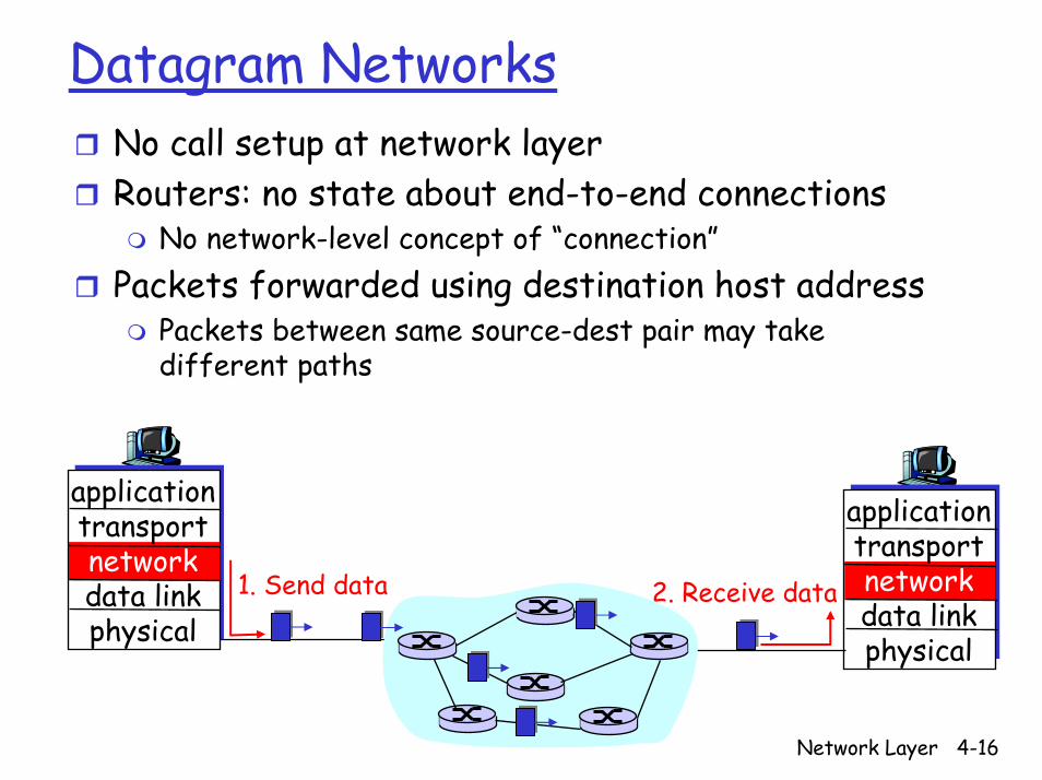
Datagram NetworksNo call setup at network layerRouters: no state about end-to-end connections
No network-level concept of “connection”Packets forwarded using destination host address
Packets between same source-dest pair may take different paths
applicationtransportnetworkdata linkphysical
applicationtransportnetworkdata linkphysical
1. Send data 2. Receive data
Network Layer 4-17
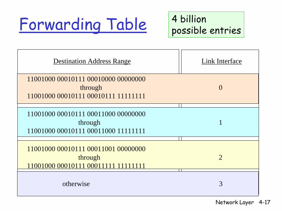
4 billion possible entriesForwarding Table
Destination Address Range Link Interface
11001000 00010111 00010000 00000000through 0
11001000 00010111 00010111 11111111
11001000 00010111 00011000 00000000through 1
11001000 00010111 00011000 11111111
11001000 00010111 00011001 00000000through 2
11001000 00010111 00011111 11111111
otherwise 3
Network Layer 4-18
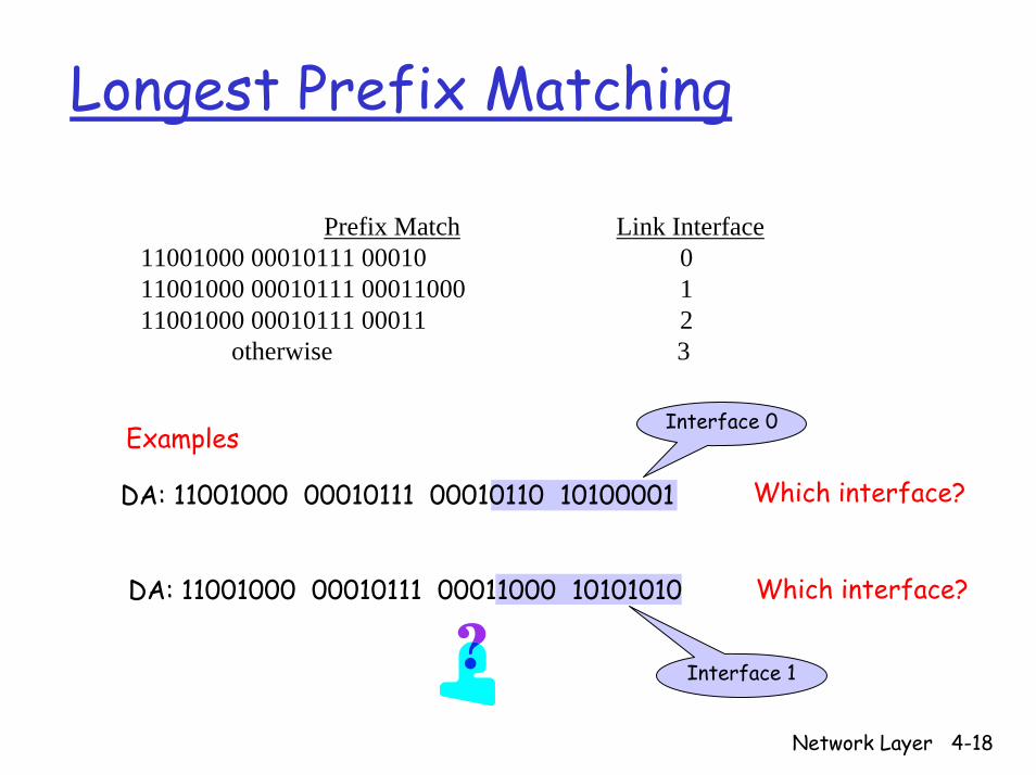
Longest Prefix Matching
Prefix Match Link Interface11001000 00010111 00010 0 11001000 00010111 00011000 111001000 00010111 00011 2
otherwise 3
Examples
Which interface?
Interface 0
DA: 11001000 00010111 00010110 10100001
Which interface?DA: 11001000 00010111 00011000 10101010
Interface 1
Network Layer 4-19
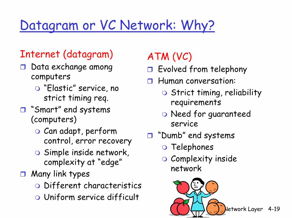
Datagram or VC Network: Why?
Internet (datagram)Data exchange among computers
“Elastic” service, no strict timing req.
“Smart” end systems (computers)
Can adapt, perform control, error recoverySimple inside network, complexity at “edge”
Many link types Different characteristicsUniform service difficult
ATM (VC)Evolved from telephonyHuman conversation:
Strict timing, reliability requirementsNeed for guaranteed service
“Dumb” end systemsTelephonesComplexity inside network
Network Layer 4-20
Chapter 4: Network Layer
4. 1 Introduction4.2 Virtual circuit and datagram networks4.3 What’s inside a router4.4 IP: Internet Protocol
Datagram formatIPv4 addressingICMPIPv6
4.5 Routing algorithmsLink stateDistance VectorHierarchical routing
4.6 Routing in the Internet
RIPOSPFBGP
Network Layer 4-21
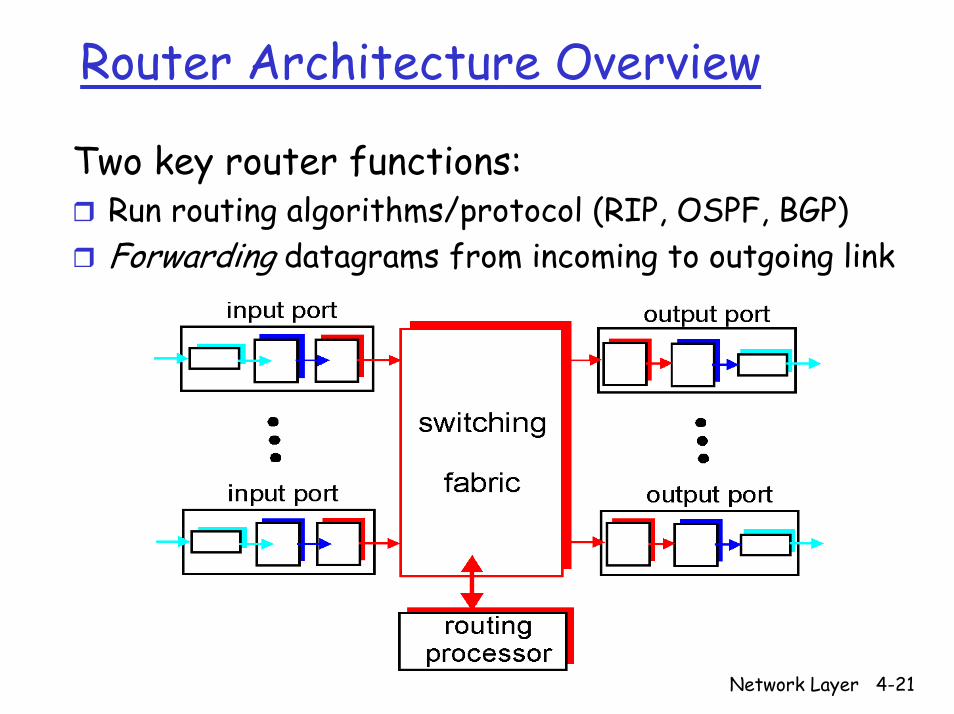
Router Architecture Overview
Two key router functions:Run routing algorithms/protocol (RIP, OSPF, BGP)Forwarding datagrams from incoming to outgoing link
Network Layer 4-22
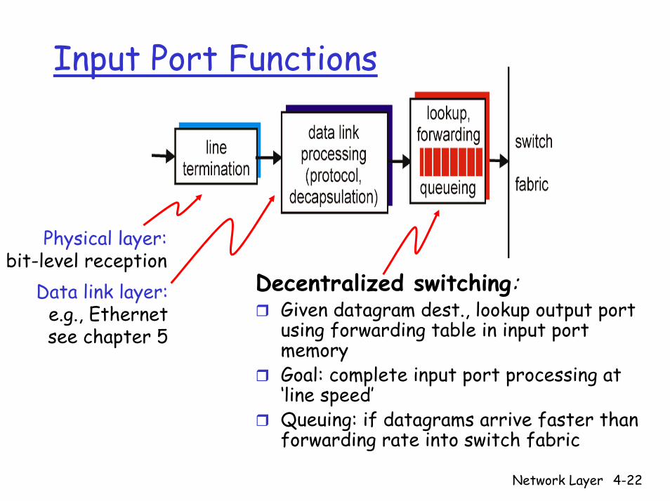
Input Port Functions
Decentralized switching:Given datagram dest., lookup output port using forwarding table in input port memoryGoal: complete input port processing at ‘line speed’Queuing: if datagrams arrive faster than forwarding rate into switch fabric
Physical layer:bit-level reception
Data link layer:e.g., Ethernetsee chapter 5
Network Layer 4-23
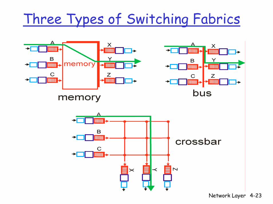
Three Types of Switching Fabrics
Network Layer 4-24
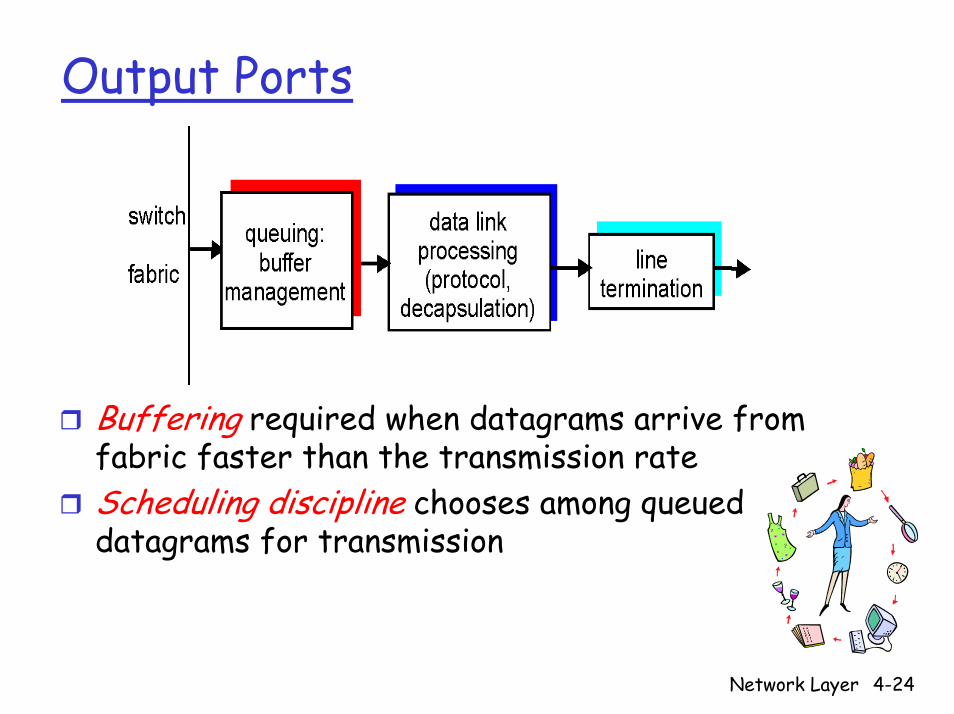
Output Ports
Buffering required when datagrams arrive from fabric faster than the transmission rateScheduling discipline chooses among queued datagrams for transmission
Network Layer 4-25
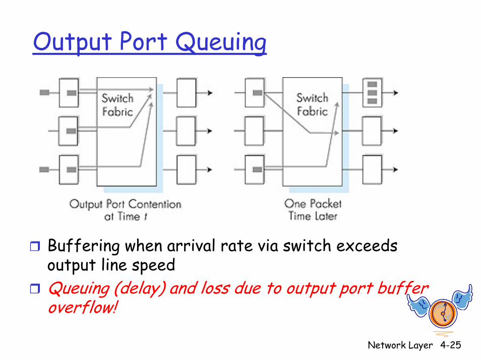
Output Port Queuing
Buffering when arrival rate via switch exceeds output line speedQueuing (delay) and loss due to output port buffer overflow!
Network Layer 4-26
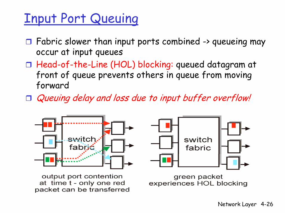
Input Port QueuingFabric slower than input ports combined -> queueing may occur at input queues Head-of-the-Line (HOL) blocking: queued datagram at front of queue prevents others in queue from moving forwardQueuing delay and loss due to input buffer overflow!
Network Layer 4-27
Chapter 4: Network Layer
4. 1 Introduction4.2 Virtual circuit and datagram networks4.3 What’s inside a router4.4 IP: Internet Protocol
Datagram formatIPv4 addressingICMPIPv6
4.5 Routing algorithmsLink stateDistance VectorHierarchical routing
4.6 Routing in the Internet
RIPOSPFBGP
Network Layer 4-28
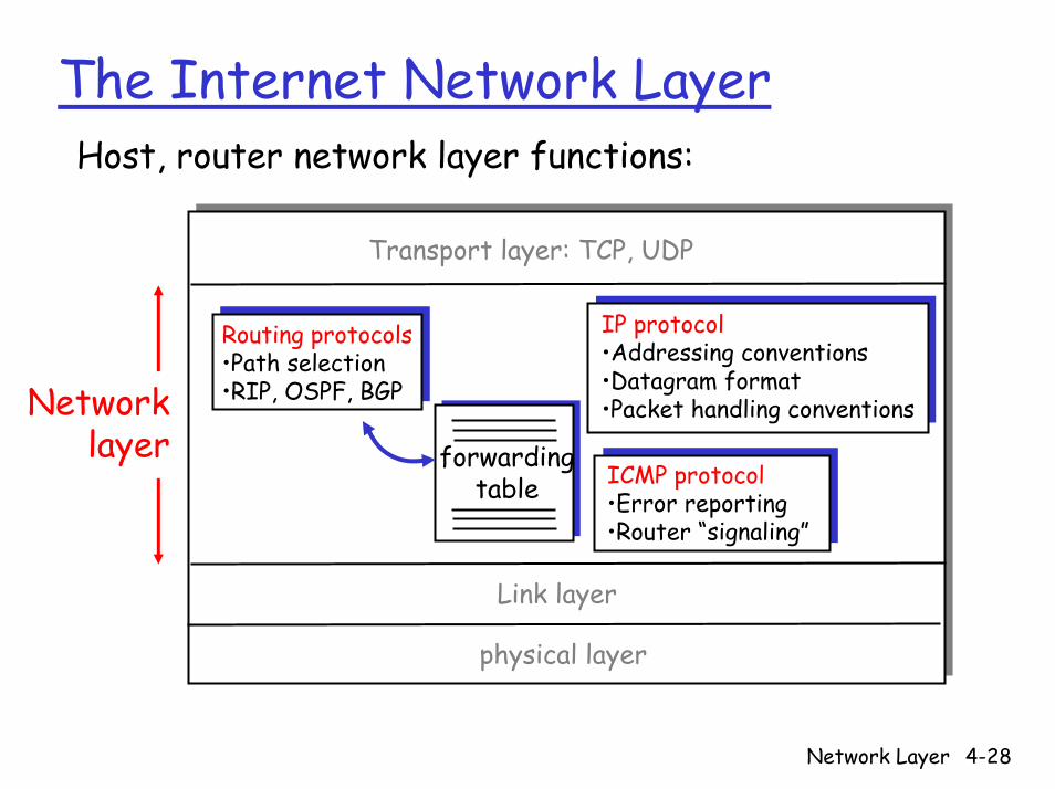
The Internet Network Layer
forwardingtable
Host, router network layer functions:
Routing protocols•Path selection•RIP, OSPF, BGP
IP protocol•Addressing conventions•Datagram format•Packet handling conventions
ICMP protocol•Error reporting•Router “signaling”
Transport layer: TCP, UDP
Link layer
physical layer
Networklayer

Network Layer 4-29
Chapter 4: Network Layer
4. 1 Introduction4.2 Virtual circuit and datagram networks4.3 What’s inside a router4.4 IP: Internet Protocol
Datagram formatIPv4 addressingICMPIPv6
4.5 Routing algorithmsLink stateDistance VectorHierarchical routing
4.6 Routing in the Internet
RIPOSPFBGP
Network Layer 4-30
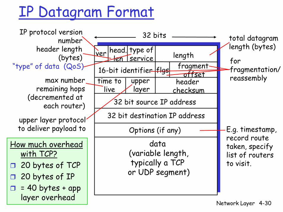
IP Datagram Format
ver length
32 bits
data (variable length,typically a TCP
or UDP segment)
16-bit identifierheader
checksumtime to
live
32 bit source IP address
head.len
type ofservice
flgs fragmentoffset
upperlayer
32 bit destination IP address
Options (if any)
IP protocol versionnumber
header length(bytes)
max numberremaining hops
(decremented at each router)
forfragmentation/reassembly
total datagramlength (bytes)
upper layer protocolto deliver payload to
“type” of data (QoS)
E.g. timestamp,record routetaken, specifylist of routers to visit.
How much overhead with TCP?20 bytes of TCP20 bytes of IP= 40 bytes + app layer overhead
Network Layer 4-31
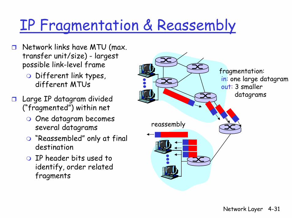
IP Fragmentation & ReassemblyNetwork links have MTU (max. transfer unit/size) - largest possible link-level frame
Different link types, different MTUs
Large IP datagram divided (“fragmented”) within net
One datagram becomes several datagrams“Reassembled” only at final destinationIP header bits used to identify, order related fragments
fragmentation: in: one large datagramout: 3 smaller
datagrams
reassembly

Network Layer 4-32
IP Fragmentation & ReassemblyID=x
offset=0
fragflag=0
length=4000
ID=x
offset=0
fragflag=1
length=1500
ID=x
offset=185
fragflag=1
length=1500
ID=x
offset=370
fragflag=0
length=1040
One large datagram becomesseveral smaller datagrams
Example4000 byte datagramMTU = 1500 bytes
1480 bytes in data field
offset =1480/8
Network Layer 4-33
Chapter 4: Network Layer
4. 1 Introduction4.2 Virtual circuit and datagram networks4.3 What’s inside a router4.4 IP: Internet Protocol
Datagram formatIPv4 addressingICMPIPv6
4.5 Routing algorithmsLink stateDistance VectorHierarchical routing
4.6 Routing in the Internet
RIPOSPFBGP
Network Layer 4-34
IP Addressing: Introduction223.1.1.1
223.1.1.2
223.1.1.3
223.1.1.4 223.1.2.9
223.1.2.2
223.1.2.1
223.1.3.2223.1.3.1
223.1.3.27
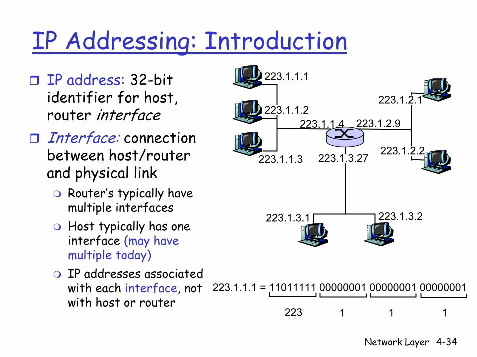
IP address: 32-bit identifier for host, router interfaceInterface: connection between host/router and physical link
Router’s typically have multiple interfacesHost typically has one interface (may have multiple today)IP addresses associated with each interface, not with host or router
223.1.1.1 = 11011111 00000001 00000001 00000001
223 1 11

Network Layer 4-35
Subnets223.1.1.1
223.1.1.2
223.1.1.3
223.1.1.4 223.1.2.9
223.1.2.2
223.1.2.1
223.1.3.2223.1.3.1
223.1.3.27
subnet
IP address:Subnet part (high order bits)Host part (low order bits)
What’s a subnet ?Device interfaces with same subnet part of IP addressCan physically reach each other without intervening router network consisting of 3 subnets
(for IP addresses starting with 223, first 24 bits are network address)

Network Layer 4-36
IP AddressesGiven notion of “network”, let’s re-examine IP addresses:
“class-full” addressing:
class1.0.0.0 to127.255.255.255A 0network host
128.0.0.0 to191.255.255.255
B 10 network host
192.0.0.0 to223.255.255.255C 110 network host
224.0.0.0 to239.255.255.255D 1110 multicast address
32 bits
Network Layer 4-37
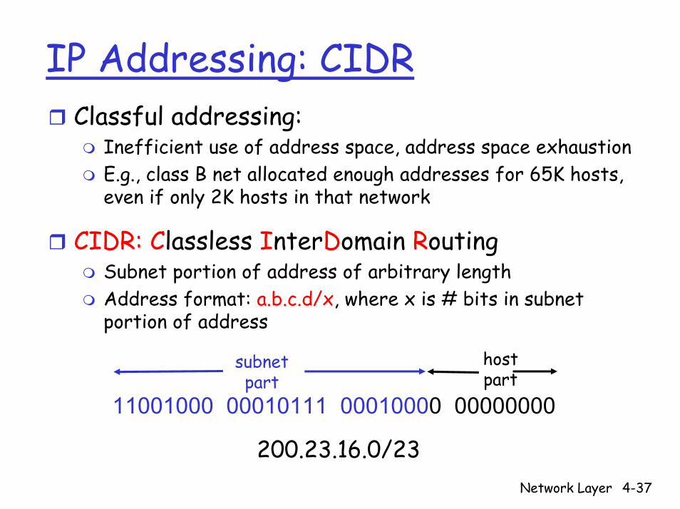
IP Addressing: CIDRClassful addressing:
Inefficient use of address space, address space exhaustionE.g., class B net allocated enough addresses for 65K hosts, even if only 2K hosts in that network
CIDR: Classless InterDomain RoutingSubnet portion of address of arbitrary lengthAddress format: a.b.c.d/x, where x is # bits in subnet portion of address
11001000 00010111 00010000 00000000
subnetpart
hostpart
200.23.16.0/23
Network Layer 4-38
IP Addresses: How to Get One?
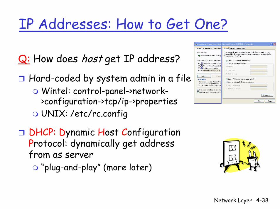
Q: How does host get IP address?
Hard-coded by system admin in a fileWintel: control-panel->network->configuration->tcp/ip->propertiesUNIX: /etc/rc.config
DHCP: Dynamic Host Configuration Protocol: dynamically get address from as server
“plug-and-play” (more later)
Network Layer 4-39
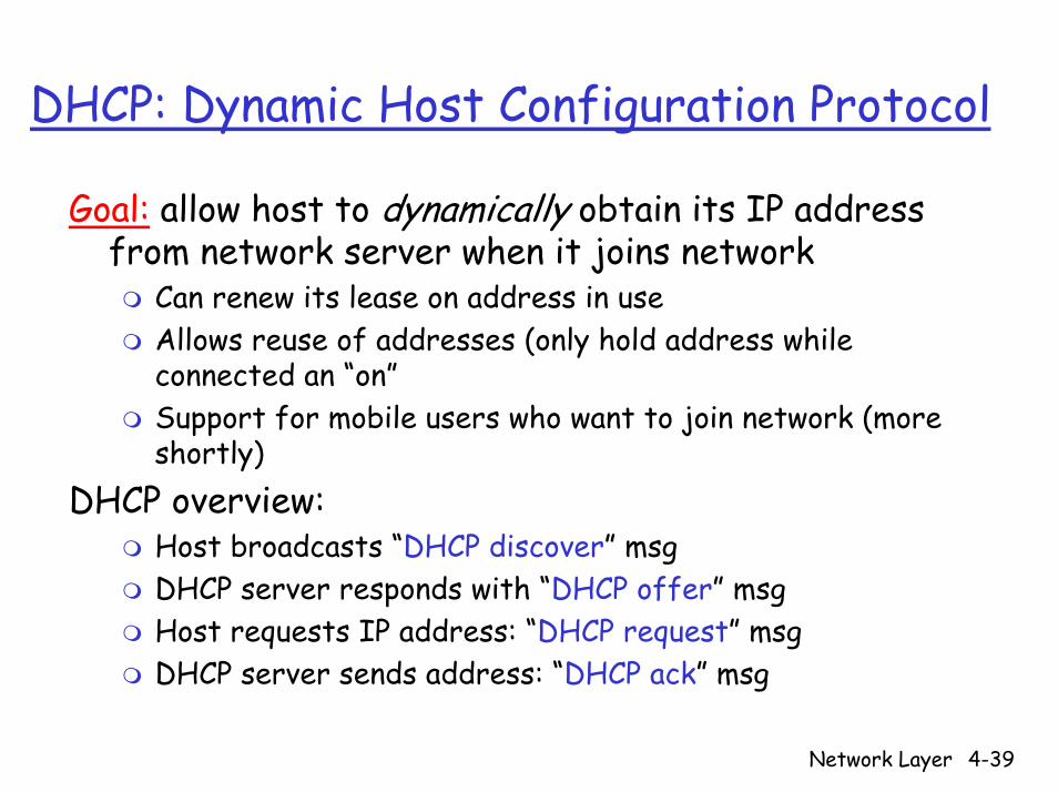
DHCP: Dynamic Host Configuration Protocol
Goal: allow host to dynamically obtain its IP address from network server when it joins network
Can renew its lease on address in useAllows reuse of addresses (only hold address while connected an “on”Support for mobile users who want to join network (more shortly)
DHCP overview:Host broadcasts “DHCP discover” msgDHCP server responds with “DHCP offer” msgHost requests IP address: “DHCP request” msgDHCP server sends address: “DHCP ack” msg
Network Layer 4-40
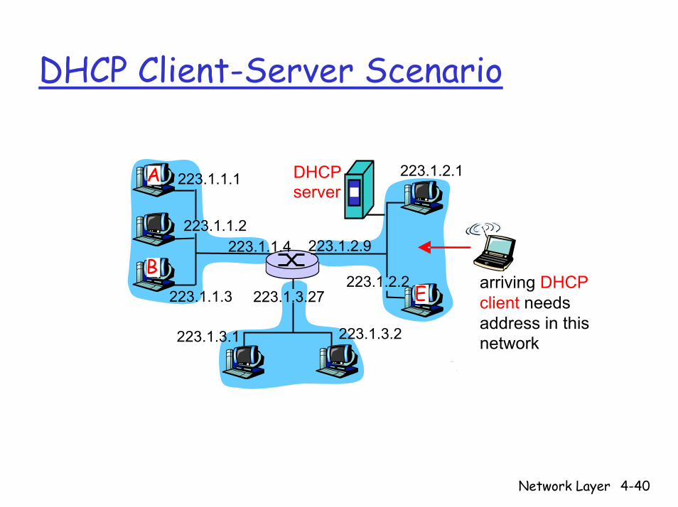
DHCP Client-Server Scenario
223.1.1.1
223.1.1.2
223.1.1.3
223.1.1.4 223.1.2.9
223.1.2.2
223.1.2.1
223.1.3.2223.1.3.1
223.1.3.27
A
BE
DHCP server
arriving DHCP client needsaddress in thisnetwork
Network Layer 4-41
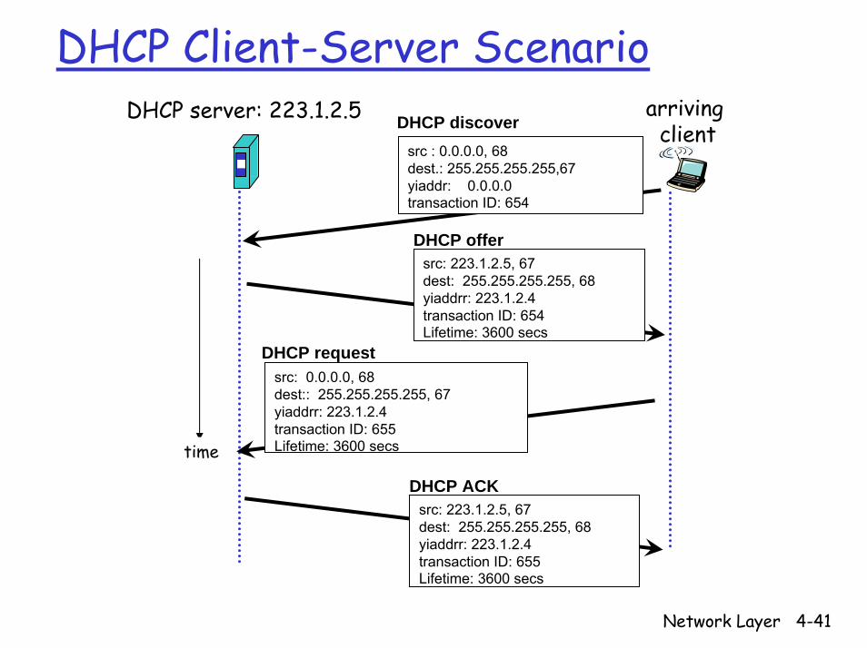
DHCP Client-Server ScenarioDHCP server: 223.1.2.5 arriving
client
time
DHCP discoversrc : 0.0.0.0, 68 dest.: 255.255.255.255,67yiaddr: 0.0.0.0transaction ID: 654
DHCP offersrc: 223.1.2.5, 67 dest: 255.255.255.255, 68yiaddrr: 223.1.2.4transaction ID: 654Lifetime: 3600 secs
DHCP requestsrc: 0.0.0.0, 68 dest:: 255.255.255.255, 67yiaddrr: 223.1.2.4transaction ID: 655Lifetime: 3600 secs
DHCP ACKsrc: 223.1.2.5, 67 dest: 255.255.255.255, 68yiaddrr: 223.1.2.4transaction ID: 655Lifetime: 3600 secs
Network Layer 4-42
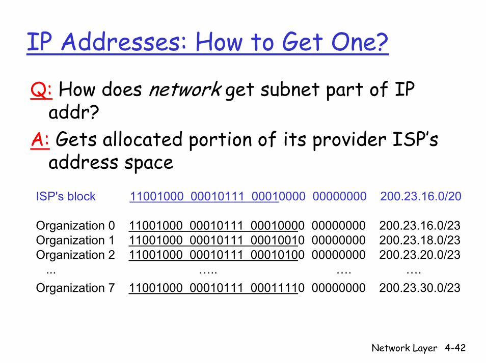
IP Addresses: How to Get One?
Q: How does network get subnet part of IP addr?
A: Gets allocated portion of its provider ISP’s address space
ISP's block 11001000 00010111 00010000 00000000 200.23.16.0/20
Organization 0 11001000 00010111 00010000 00000000 200.23.16.0/23 Organization 1 11001000 00010111 00010010 00000000 200.23.18.0/23 Organization 2 11001000 00010111 00010100 00000000 200.23.20.0/23
... ….. …. ….Organization 7 11001000 00010111 00011110 00000000 200.23.30.0/23
Network Layer 4-43
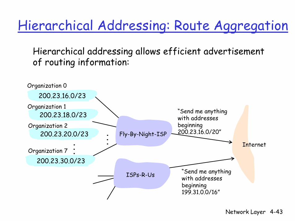
Hierarchical Addressing: Route Aggregation
Hierarchical addressing allows efficient advertisement of routing information:
“Send me anythingwith addresses beginning 200.23.16.0/20”
200.23.16.0/23
200.23.18.0/23
200.23.30.0/23
Fly-By-Night-ISP
Organization 0
Organization 7Internet
Organization 1
ISPs-R-Us “Send me anythingwith addresses beginning 199.31.0.0/16”
200.23.20.0/23Organization 2
...
...
Network Layer 4-44
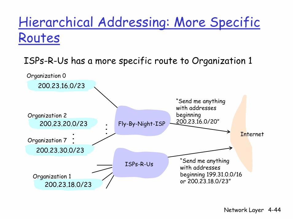
Hierarchical Addressing: More Specific Routes
ISPs-R-Us has a more specific route to Organization 1
“Send me anythingwith addresses beginning 200.23.16.0/20”
200.23.16.0/23
200.23.18.0/23
200.23.30.0/23
Fly-By-Night-ISP
Organization 0
Organization 7Internet
Organization 1
ISPs-R-Us “Send me anythingwith addresses beginning 199.31.0.0/16or 200.23.18.0/23”
200.23.20.0/23Organization 2
...
...

Network Layer 4-45
IP Addressing: the Last Word...
Q: How does an ISP get block of addresses?
A: ICANN: Internet Corporation for Assigned Names and Numbers
Allocates addressesManages DNSAssigns domain names, resolves disputes
Network Layer 4-46
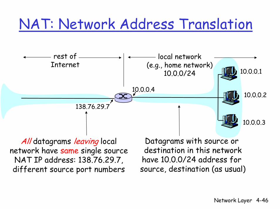
NAT: Network Address Translation
10.0.0.1
10.0.0.2
10.0.0.3
10.0.0.4
138.76.29.7
local network(e.g., home network)
10.0.0/24
rest ofInternet
Datagrams with source or destination in this networkhave 10.0.0/24 address for source, destination (as usual)
All datagrams leaving localnetwork have same single source
NAT IP address: 138.76.29.7,different source port numbers
Network Layer 4-47
NAT: Network Address Translation
Motivation: local network uses just one IP address as far as outside world is concerned:
Range of addresses not needed from ISP: just one IP address for all devicesCan change addresses of devices in local network without notifying outside worldCan change ISP without changing addresses of devices in local networkDevices inside local net not explicitly addressable, visible by outside world (a security plus)

Network Layer 4-48
NAT: Network Address TranslationImplementation: NAT router must:
Outgoing datagrams: replace (source IP address, port #) of every outgoing datagram to (NAT IP address, new port #)
. . . remote clients/servers will respond using (NAT IP address, new port #) as destination addr.
Remember (in NAT translation table) every (source IP address, port #) to (NAT IP address, new port #) translation pair
Incoming datagrams: replace (NAT IP address, new port #) in dest fields of every incoming datagram with corresponding (source IP address, port #) stored in NAT table
Network Layer 4-49
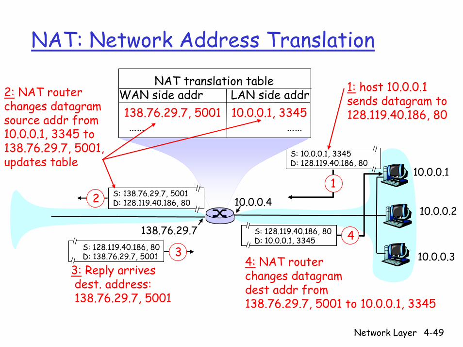
NAT: Network Address Translation
10.0.0.1
10.0.0.2
10.0.0.3
S: 10.0.0.1, 3345D: 128.119.40.186, 80
110.0.0.4
138.76.29.7
1: host 10.0.0.1 sends datagram to 128.119.40.186, 80
NAT translation tableWAN side addr LAN side addr138.76.29.7, 5001 10.0.0.1, 3345…… ……
S: 128.119.40.186, 80 D: 10.0.0.1, 3345 4
S: 138.76.29.7, 5001D: 128.119.40.186, 802
2: NAT routerchanges datagramsource addr from10.0.0.1, 3345 to138.76.29.7, 5001,updates table
S: 128.119.40.186, 80 D: 138.76.29.7, 5001 3
3: Reply arrivesdest. address:138.76.29.7, 5001
4: NAT routerchanges datagramdest addr from138.76.29.7, 5001 to 10.0.0.1, 3345
Network Layer 4-50
NAT: Network Address Translation
Outside node cannot initiate the communication
Reserved addresses:10.0.0.0 - 10.255.255.255/8172.16.0.0 – 172.31.255.255/12192.168.0.0 – 192.168.255.255/16
Network Layer 4-51
NAT: Network Address Translation
16-bit port-number field: 60,000 simultaneous connections with a single LAN-side address!
NAT is controversial:Routers should only process up to layer 3Violates end-to-end argument
• NAT possibility must be taken into account by app designers, eg, P2P applications
Address shortage should instead be solved by IPv6
Network Layer 4-52
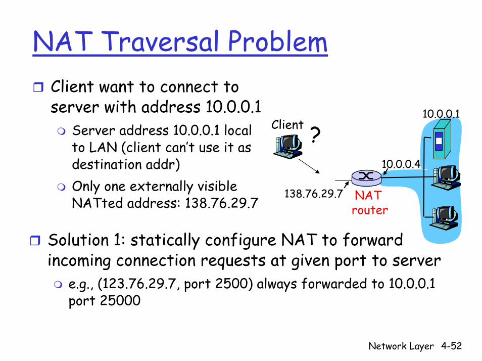
NAT Traversal ProblemClient want to connect to server with address 10.0.0.1
Server address 10.0.0.1 local to LAN (client can’t use it as destination addr)Only one externally visible NATted address: 138.76.29.7
10.0.0.1
10.0.0.4
NAT router
138.76.29.7
Client ?
Solution 1: statically configure NAT to forward incoming connection requests at given port to server
e.g., (123.76.29.7, port 2500) always forwarded to 10.0.0.1 port 25000
Network Layer 4-53
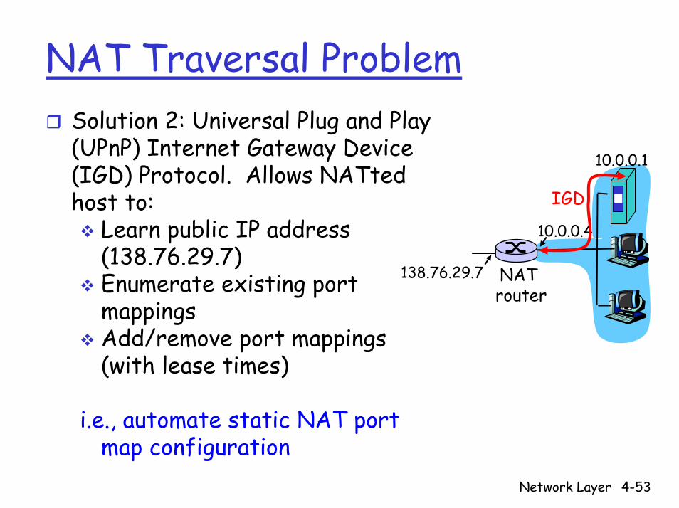
NAT Traversal ProblemSolution 2: Universal Plug and Play (UPnP) Internet Gateway Device (IGD) Protocol. Allows NATtedhost to:
Learn public IP address (138.76.29.7)Enumerate existing port mappingsAdd/remove port mappings (with lease times)
i.e., automate static NAT port map configuration
10.0.0.1
10.0.0.4
NAT router
138.76.29.7
IGD

Network Layer 4-54
NAT Traversal ProblemSolution 3: relaying (used in Skype)
NATed server establishes connection to relayExternal client connects to relayRelay bridges packets between to connections
10.0.0.1
NAT router
138.76.29.7Client
1. connection torelay initiatedby NATted host
2. connection torelay initiatedby client
3. relaying established
Network Layer 4-55
Chapter 4: Network Layer
4. 1 Introduction4.2 Virtual circuit and datagram networks4.3 What’s inside a router4.4 IP: Internet Protocol
Datagram formatIPv4 addressingICMPIPv6
4.5 Routing algorithmsLink stateDistance VectorHierarchical routing
4.6 Routing in the Internet
RIPOSPFBGP
Network Layer 4-56
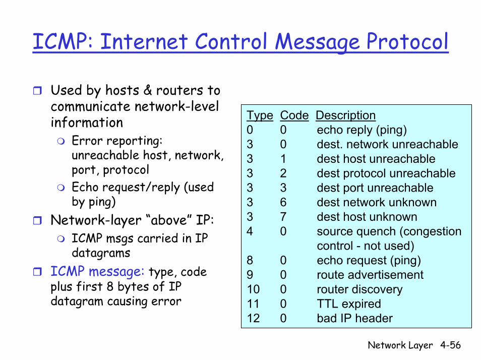
ICMP: Internet Control Message Protocol
Used by hosts & routers to communicate network-level information
Error reporting: unreachable host, network, port, protocolEcho request/reply (used by ping)
Network-layer “above” IP:ICMP msgs carried in IP datagrams
ICMP message: type, code plus first 8 bytes of IP datagram causing error
Type Code Description0 0 echo reply (ping)3 0 dest. network unreachable3 1 dest host unreachable3 2 dest protocol unreachable3 3 dest port unreachable3 6 dest network unknown3 7 dest host unknown4 0 source quench (congestion
control - not used)8 0 echo request (ping)9 0 route advertisement10 0 router discovery11 0 TTL expired12 0 bad IP header
Network Layer 4-57
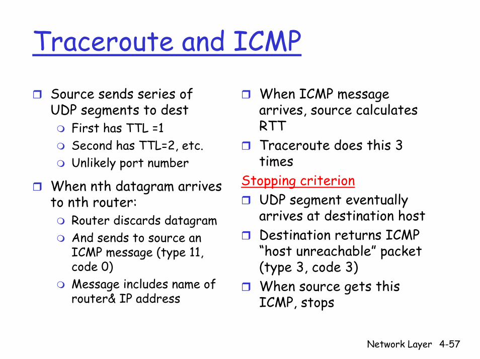
Traceroute and ICMP
Source sends series of UDP segments to dest
First has TTL =1Second has TTL=2, etc.Unlikely port number
When nth datagram arrives to nth router:
Router discards datagramAnd sends to source an ICMP message (type 11, code 0)Message includes name of router& IP address
When ICMP message arrives, source calculates RTTTraceroute does this 3 times
Stopping criterionUDP segment eventually arrives at destination hostDestination returns ICMP “host unreachable” packet (type 3, code 3)When source gets this ICMP, stops

Network Layer 4-58
ICMP: Brief Summary
ICMP is the control sibling of IP ICMP is used by IP and uses IP as network layer protocol ICMP is used for ping, traceroute, and path MTU discovery
Ping: Uses ICMP Echo request/reply messagesPath MTU Discovery
• Send a large IP datagram with “No fragment” bit set • Reduce size until success (No ICMP message received)

Network Layer 4-59
Chapter 4: Network Layer
4. 1 Introduction4.2 Virtual circuit and datagram networks4.3 What’s inside a router4.4 IP: Internet Protocol
Datagram formatIPv4 addressingICMPIPv6
4.5 Routing algorithmsLink stateDistance VectorHierarchical routing
4.6 Routing in the Internet
RIPOSPFBGP

Network Layer 4-60
IPv6Initial motivation: 32-bit address space soon to be completely allocatedAdditional motivation:
Header format helps speed processing/forwardingHeader changes to facilitate QoS
IPv6 datagram format:Fixed-length 40 byte headerNo fragmentation allowed

Network Layer 4-61
IPv6 Header (Cont.)Priority: identify priority among datagrams in flowFlow Label: identify datagrams in same “flow”
(concept of“flow” not well defined)Next header: identify upper layer protocol for data

Network Layer 4-62
Other Changes from IPv4
Checksum: removed entirely to reduce processing time at each hopOptions: allowed, but outside of header, indicated by “Next Header”fieldICMPv6: new version of ICMP
Additional message types, e.g. “Packet Too Big”Multicast group management functions
Network Layer 4-63
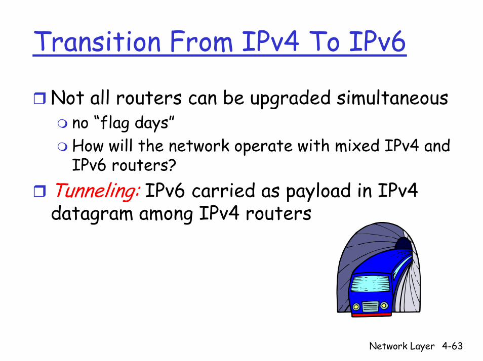
Transition From IPv4 To IPv6
Not all routers can be upgraded simultaneousno “flag days”How will the network operate with mixed IPv4 and IPv6 routers?
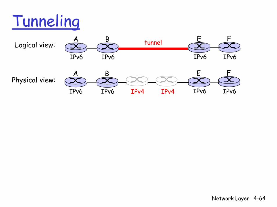
Tunneling: IPv6 carried as payload in IPv4 datagram among IPv4 routers
Network Layer 4-64
TunnelingA B E F
IPv6 IPv6 IPv6 IPv6
tunnelLogical view:
Physical view:A B E F
IPv6 IPv6 IPv6 IPv6IPv4 IPv4

Network Layer 4-65
TunnelingA B E F
IPv6 IPv6 IPv6 IPv6
tunnelLogical view:
A B E F
IPv6 IPv6 IPv6 IPv6
C D
IPv4 IPv4
Flow: XSrc: ADest: F
data
Flow: XSrc: ADest: F
data
Flow: XSrc: ADest: F
data
Src:BDest: E
Flow: XSrc: ADest: F
data
Src:BDest: E
A-to-B:IPv6
E-to-F:IPv6
Physical view:
B-to-C:IPv6 inside
IPv4
B-to-C:IPv6 inside
IPv4

Network Layer 4-66
Chapter 4: Network Layer
4. 1 Introduction4.2 Virtual circuit and datagram networks4.3 What’s inside a router4.4 IP: Internet Protocol
Datagram formatIPv4 addressingICMPIPv6
4.5 Routing algorithmsLink stateDistance VectorHierarchical routing
4.6 Routing in the Internet
RIPOSPFBGP
Network Layer 4-67
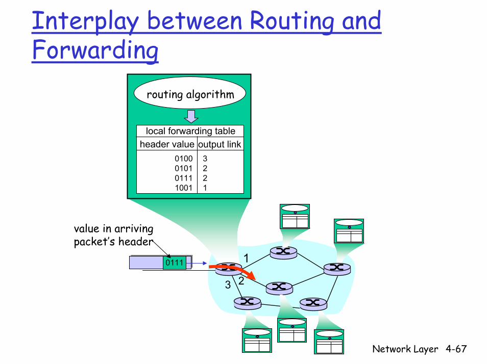
Interplay between Routing and Forwarding
1
23
0111
value in arrivingpacket’s header
routing algorithm
local forwarding tableheader value output link
0100010101111001
3221

Network Layer 4-68
Graph Abstraction
u
yx
wv
z2
21
3
1
1
2
53
5
Graph: G = (N,E)
N = set of routers = { u, v, w, x, y, z }
E = set of links ={ (u,v), (u,x), (v,x), (v,w), (x,w), (x,y), (w,y), (w,z), (y,z) }
Remark: Graph abstraction is useful in other network contexts
Example: P2P, where N is set of peers and E is set of TCP connections

Network Layer 4-69
Graph Abstraction: Costs
u
yx
wv
z2
21
3
1
1
2
53
5 • c(x,x’) = cost of link (x,x’)
- e.g., c(w,z) = 5
• Cost could always be 1, or inversely related to bandwidth,or inversely related to congestion
Cost of path (x1, x2, x3,…, xp) = c(x1,x2) + c(x2,x3) + … + c(xp-1,xp)
Question: What’s the least-cost path between u and z ?
Routing algorithm: algorithm that finds “least-cost” path
Network Layer 4-70
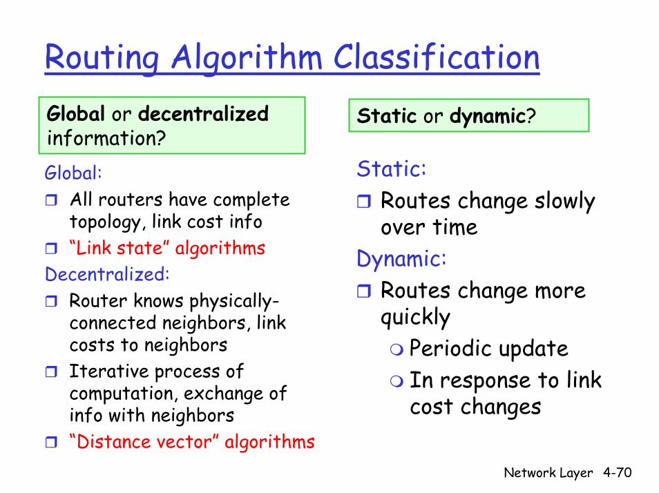
Routing Algorithm ClassificationGlobal or decentralizedinformation?
Static or dynamic?
Static:Routes change slowly over time
Dynamic:Routes change more quickly
Periodic updateIn response to link cost changes
Global:All routers have complete topology, link cost info“Link state” algorithms
Decentralized:Router knows physically-connected neighbors, link costs to neighborsIterative process of computation, exchange of info with neighbors“Distance vector” algorithms

Network Layer 4-71
Chapter 4: Network Layer
4. 1 Introduction4.2 Virtual circuit and datagram networks4.3 What’s inside a router4.4 IP: Internet Protocol
Datagram formatIPv4 addressingICMPIPv6
4.5 Routing algorithmsLink stateDistance VectorHierarchical routing
4.6 Routing in the Internet
RIPOSPFBGP

Network Layer 4-72
A Link-State Routing Algorithm
Dijkstra’s algorithmNet topology, link costs known to all nodes
Accomplished via “link state broadcast”All nodes have same info
Computes least cost paths from one node (‘source”) to all other nodes
Gives forwarding tablefor that node
Iterative: after k iterations, know least cost path to k dest.’s
Notation:c(x,y): link cost from node x to y; = ∞ if not direct neighborsD(v): current value of cost of path from source to dest. vp(v): predecessor node along path from source to vN': set of nodes whose least cost path definitively known

Network Layer 4-73
Dijkstra’s Algorithm1 Initialization:2 N' = {u} 3 for all nodes v 4 if v adjacent to u 5 then D(v) = c(u,v) 6 else D(v) = ∞7 8 Loop9 find w not in N' such that D(w) is a minimum 10 add w to N'11 update D(v) for all v adjacent to w and not in N' : 12 D(v) = min( D(v), D(w) + c(w,v) ) 13 /* new cost to v is either old cost to v or known 14 shortest path cost to w plus cost from w to v */ 15 until all nodes in N'

Network Layer 4-74
Dijkstra’s Algorithm: Example
Step012345
start NA
D(B),p(B)2,A
D(C),p(C)5,A
D(D),p(D)1,A
D(E),p(E)∞
D(F),p(F)∞
2,A2,A 4,D
3,E3,E
2,D ∞4,E4,E4,E
ADEBCFADEBC
ADEBADE
AD
A
ED
CB
F2
21
3
1
1
2
53
5
Network Layer 4-75
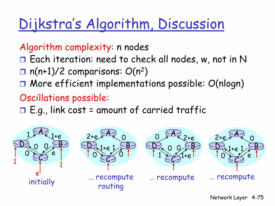
Dijkstra’s Algorithm, DiscussionAlgorithm complexity: n nodes
Each iteration: need to check all nodes, w, not in Nn(n+1)/2 comparisons: O(n2)More efficient implementations possible: O(nlogn)
Oscillations possible:E.g., link cost = amount of carried traffic
AD
CB
1 1+e
e0
e1 1
0 0
AD
CB
2+e 0
001+e 1
AD
CB
0 2+e
1+e10 0
AD
CB
2+e 0
e01+e 1
initially … recomputerouting
… recompute … recompute
Network Layer 4-76
Chapter 4: Network Layer
4. 1 Introduction4.2 Virtual circuit and datagram networks4.3 What’s inside a router4.4 IP: Internet Protocol
Datagram formatIPv4 addressingICMPIPv6
4.5 Routing algorithmsLink stateDistance VectorHierarchical routing
4.6 Routing in the Internet
RIPOSPFBGP
Network Layer 4-77
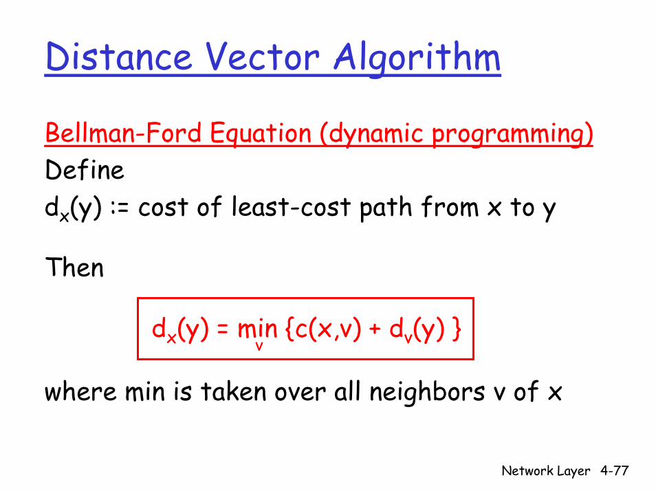
Distance Vector Algorithm
Bellman-Ford Equation (dynamic programming)Definedx(y) := cost of least-cost path from x to y
Then
dx(y) = min {c(x,v) + dv(y) }
where min is taken over all neighbors v of x
v
Network Layer 4-78
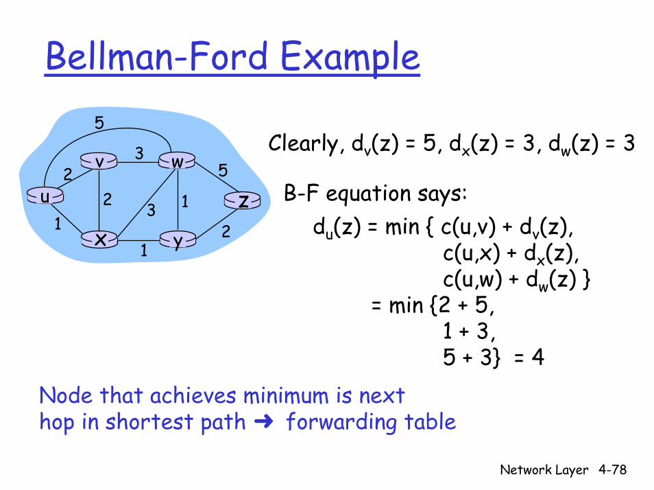
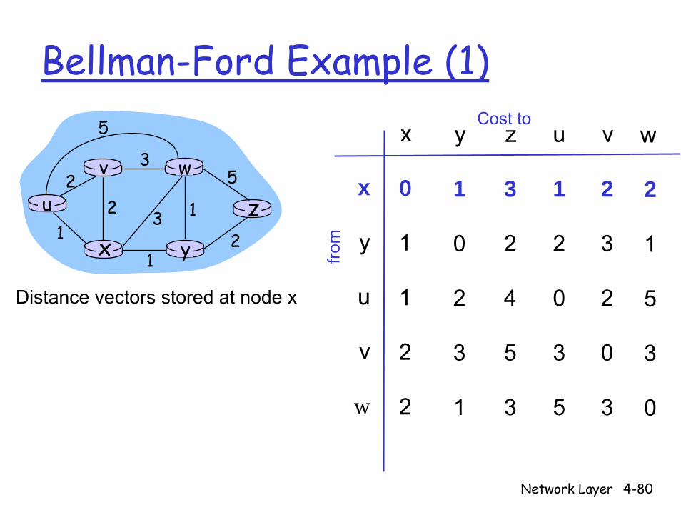
Bellman-Ford Example
u
yx
wv
z2
21
3
1
1
2
53
5Clearly, dv(z) = 5, dx(z) = 3, dw(z) = 3
du(z) = min { c(u,v) + dv(z),c(u,x) + dx(z),c(u,w) + dw(z) }
= min {2 + 5,1 + 3,5 + 3} = 4
B-F equation says:
Node that achieves minimum is nexthop in shortest path ➜ forwarding table
Network Layer 4-79
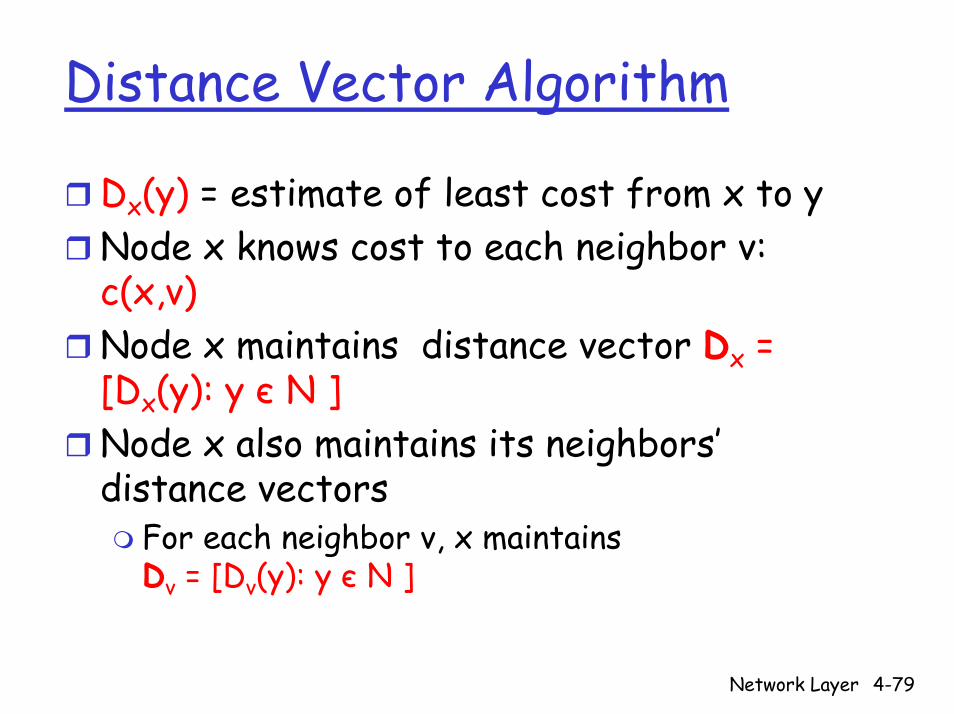
Distance Vector Algorithm
Dx(y) = estimate of least cost from x to yNode x knows cost to each neighbor v: c(x,v)Node x maintains distance vector Dx = [Dx(y): y є N ]Node x also maintains its neighbors’distance vectors
For each neighbor v, x maintains Dv = [Dv(y): y є N ]
Network Layer 4-80
Bellman-Ford Example (1)Cost to
y
1
0
2
3
1
x
y
u
v
w
x
0
1
1
2
2
z
3
2
4
5
3
from
u
1
2
0
3
5
v
2
3
2
0
3
w
2
1
5
3
0
u
yx
wv
z2
21
3
1
1
2
53
5
Distance vectors stored at node x
Network Layer 4-81
Bellman-Ford Example (2)Cost to
y
1
0
2
3
1
x
y
u
v
w
x
0
1
1
2
2
z
3
2
4
5
3
from
u
1
2
0
3
5
v
2
3
2
0
3
w
2
1
5
3
0
u
yx
wv
z2
21
3
1
1
2
53
5
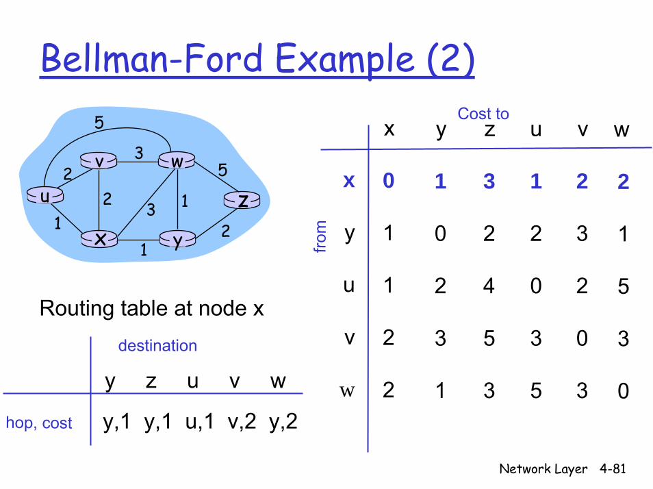
y z u v w
Routing table at node xdestination
y,1 y,1 u,1 v,2 y,2hop, cost
Network Layer 4-82
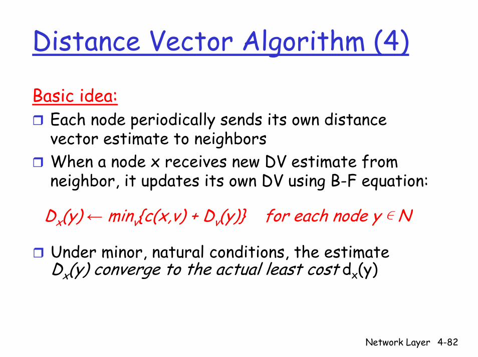
Distance Vector Algorithm (4)
Basic idea:Each node periodically sends its own distance vector estimate to neighborsWhen a node x receives new DV estimate from neighbor, it updates its own DV using B-F equation:
Dx(y) ← minv{c(x,v) + Dv(y)} for each node y ∊ N
Under minor, natural conditions, the estimate Dx(y) converge to the actual least cost dx(y)
Network Layer 4-83
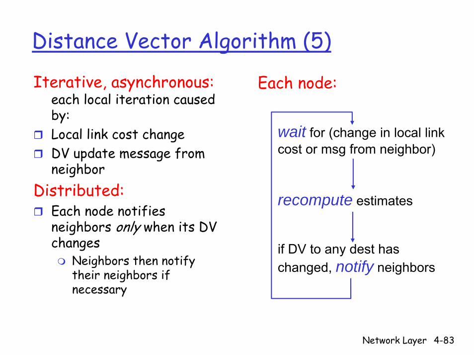
Distance Vector Algorithm (5)
Iterative, asynchronous: each local iteration caused by: Local link cost change DV update message from neighbor
Distributed:Each node notifies neighbors only when its DV changes
Neighbors then notify their neighbors if necessary
wait for (change in local link cost or msg from neighbor)
recompute estimates
if DV to any dest has changed, notify neighbors
Each node:

Network Layer 4-84
x y zxyz
0 2 7∞∞ ∞∞∞ ∞
from
cost to
from
x y zxyz
∞ ∞
∞∞ ∞
cost to
x y z
∞∞ ∞7 1 0
cost to
∞2 0 1
from
xyz
∞ ∞ ∞
node x table
node y table
node z table
x z12
7
y
time
x y zxyz
0 2 7∞∞ ∞∞∞ ∞
from
cost to
from
x y z0
from
cost to
xyz
x y zxyz
∞ ∞
∞∞ ∞
cost to
x y z
∞∞ ∞7 1 0
cost to
∞2 0 1
∞ ∞ ∞
2 0 17 1 0
x
from yz
time
x z12
7
y
node x table
node y table
node z table
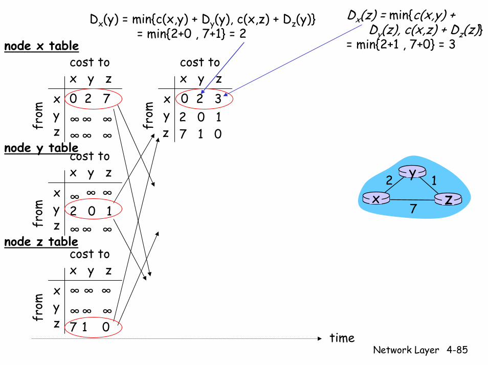
Dx(y) = min{c(x,y) + Dy(y), c(x,z) + Dz(y)} = min{2+0 , 7+1} = 2
Dx(z) = min{c(x,y) + Dy(z), c(x,z) + Dz(z)}
= min{2+1 , 7+0} = 3
32
Network Layer 4-85
x y zxyz
0 2 7∞∞ ∞∞∞ ∞
from
cost to
from
x y z0 2 3
from
cost to
xyz
x y zxyz
∞ ∞
∞∞ ∞
cost tox y zcost to
0 2 7x
from y
Network Layer 4-86
from
z
x y zxyzfr
om
0 2 7
cost tox y z
∞∞ ∞7 1 0
cost to
∞2 0 1
∞ ∞ ∞
2 0 17 1 0
2 0 13 1 0
2 0 17 1 0
xyz
time
x z12
7
y
node x table
node y table
node z table
Dx(y) = min{c(x,y) + Dy(y), c(x,z) + Dz(y)} = min{2+0 , 7+1} = 2
Dx(z) = min{c(x,y) + Dy(z), c(x,z) + Dz(z)}
= min{2+1 , 7+0} = 3

x y zxyz
0 2 7∞∞ ∞∞∞ ∞
from
cost to
from
x y zxyz
0 2 3
from
cost tox y z0 2 3
from
cost to
xyz
x y zxyz
∞ ∞
∞∞ ∞
cost tox y z0 2 7
from
cost to
Network Layer 4-87
from
xyz
x y zcost to
0 2 3xyzfr
omx y z
xyz
0 2 3
from
cost tox y z
z
0 2 7
from
cost to
xy
x y z
∞∞ ∞7 1 0
cost to
∞2 0 1
∞ ∞ ∞
2 0 17 1 0
2 0 17 1 0
2 0 13 1 0
2 0 13 1 0
2 0 1
3 1 02 0 1
3 1 0
xyz
time
x z12
7
y
node x table
node y table
node z table
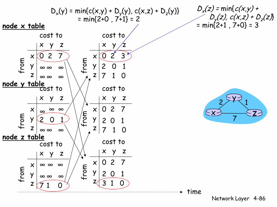
Dx(y) = min{c(x,y) + Dy(y), c(x,z) + Dz(y)} = min{2+0 , 7+1} = 2
Dx(z) = min{c(x,y) + Dy(z), c(x,z) + Dz(z)}
= min{2+1 , 7+0} = 3
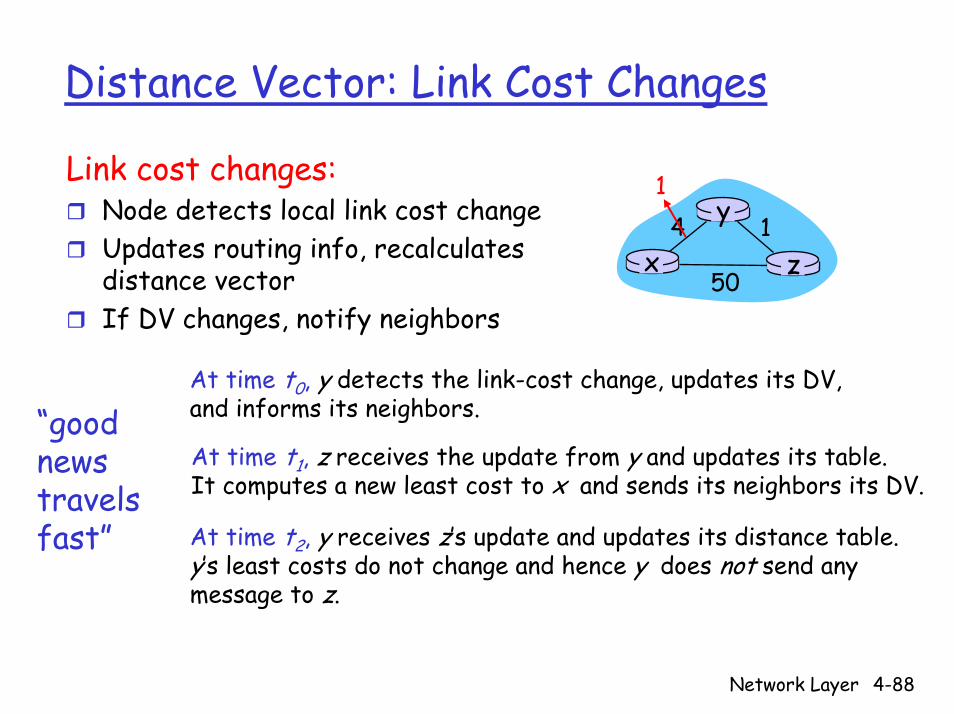
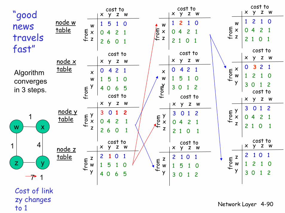
Distance Vector: Link Cost Changes
Link cost changes:Node detects local link cost change Updates routing info, recalculates distance vectorIf DV changes, notify neighbors
“goodnews travelsfast”
x z14
50
y1
At time t0, y detects the link-cost change, updates its DV, and informs its neighbors.
At time t1, z receives the update from y and updates its table. It computes a new least cost to x and sends its neighbors its DV.
At time t2, y receives z’s update and updates its distance table. y’s least costs do not change and hence y does not send any message to z.
Network Layer 4-88

Network Layer 4-89
x y z w
wxz
1 5 1 0
from
cost to
0 4 2 12 6 0 1
node w table
xwy
cost tox y z w0 4 2 1
from 1 5 1 0
4 0 6 5
node x table
x y z w
yxz
4 0 6 5
from 0 4 2 1
2 6 0 1
cost to
x y z w
zwy
2 6 0 1
from 1 5 1 0
4 0 6 5
cost to
node y table
node z table
“goodnews travelsfast”
Initial routing table (before change)
x
yz
w1
41
7
Network Layer 4-90
x y z w
wxz
1 5 1 0
from
cost to
0 4 2 12 6 0 1
node w table
from
xwy
cost tox y z w0 4 2 11 5 1 04 0 6 5
node x table
x y z w
yxz
3 0 1 2
from 0 4 2 1
2 6 0 1
cost to
x y z w
zwy
2 1 0 1
from 1 5 1 0
4 0 6 5
cost to
x y z w
wxz
1 2 1 0
from
cost to
0 4 2 12 1 0 1
from
xwy
cost tox y z w0 4 2 11 5 1 03 0 1 2
x y z w
yxz
3 0 1 2
from 0 4 2 1
2 1 0 1
cost to
x y z w
zwy
2 1 0 1fr
om 1 5 1 03 0 1 2
cost to
cost tox y z w
wxz
1 2 1 0
from 0 4 2 1
2 1 0 1
xwy
cost tox y z w0 3 2 1
from 1 2 1 0
3 0 1 2
x y z w
yxz
3 0 1 2
from 0 4 2 1
2 1 0 1
cost to
x y z w
zwy
2 1 0 1
from 1 2 1 0
3 0 1 2
cost to
“goodnews travelsfast”
Algorithm converges in 3 steps.
node y table
x
yz
w1
41 node z table
17
Cost of link zy changes to 1

Network Layer 4-91
cost tox y z w
wxz
1 2 1 0
from 0 3 2 1
2 1 0 1
xwy
cost tox y z w0 3 2 1
from 1 2 1 0
3 0 1 2
x y z w
yxz
3 0 1 2
from 0 3 2 1
2 1 0 1
cost to
x y z w
zwy
2 1 0 1
from 1 2 1 0
3 0 1 2
cost to
cost tox y z w
wxz
1 2 1 0
from 0 4 2 1
2 1 0 1
xwy
cost tox y z w0 3 2 1
from 1 2 1 0
3 0 1 2
x y z w
yxz
3 0 1 2
from 0 4 2 1
2 1 0 1
cost to
x y z w
zwy
2 1 0 1
from 1 2 1 0
3 0 1 2
cost to
“goodnews travelsfast”
node w table
node x tableAlgorithm
converges in 3 steps.
node y table
x
yz
w1
41 node z table
17
Cost of link zy changes to 1
Network Layer 4-92
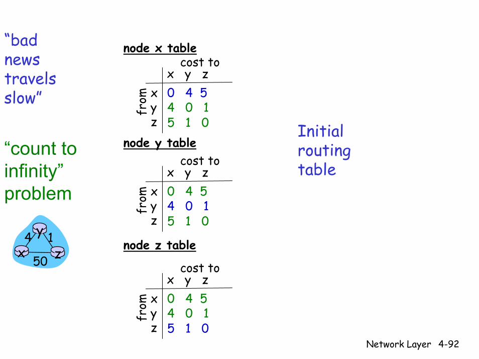
“badnews travelsslow” x
yz
cost tox y z0 4 5
from 4 0 1
5 1 0
node x table
node y table
node z table
xyz
cost tox y z0 4 5
from 4 0 1
5 1 0
xyz
cost tox y z0 4 5
from 4 0 1
5 1 0
Initial routing table
“count to infinity”problem
x z14
50
y
Network Layer 4-93
x z14
50
y60
xyz
cost tox y z0 51 50
from 4 0 1
5 1 0
node x table
node y table
node z table
xyz
cost tox y z0 4 5
from 6 0 1
5 1 0
xyz
cost tox y z0 4 5
from 4 0 1
5 1 0
xyz
cost tox y z0 51 50
from 6 0 1
5 1 0
node x table
node y table
node z table
xyz
cost tox y z0 51 50
from 6 0 1
5 1 0
xyz
cost tox y z0 51 50
from 6 0 1
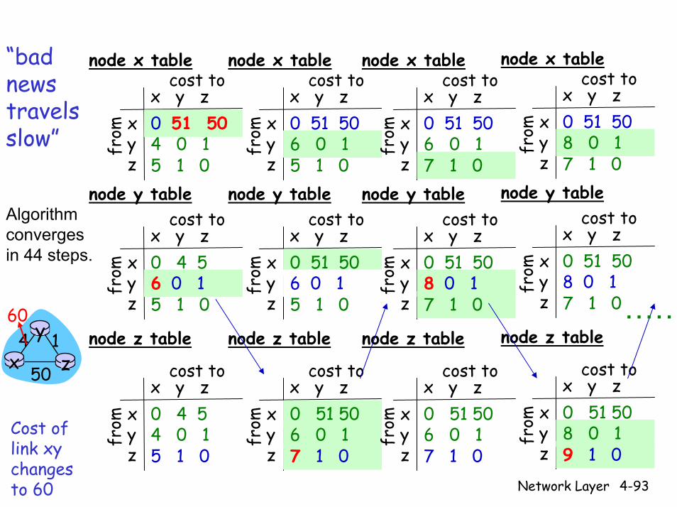
7 1 0Cost of link xy changes to 60
“badnews travelsslow”
xyz
cost tox y z0 51 50
from 6 0 1
7 1 0
node x table
node y table
node z table
xyz
cost tox y z0 51 50
from 8 0 1
7 1 0
xyz
cost tox y z0 51 50
from 6 0 1
7 1 0
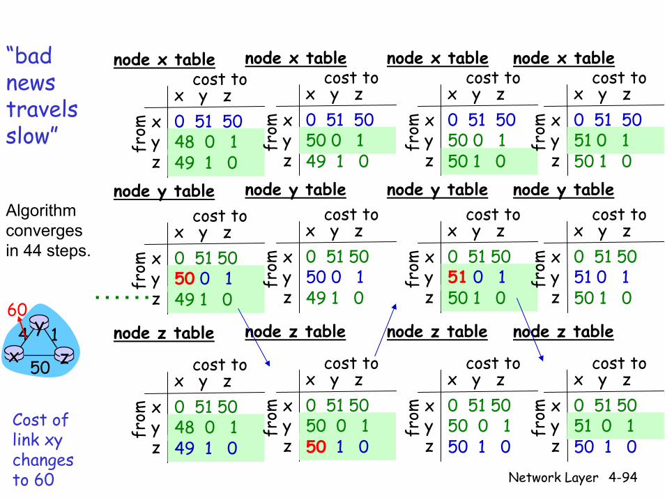
Algorithm converges in 44 steps.
xyz
cost tox y z0 51 50
from 8 0 1
7 1 0
node x table
node y table
node z table
xyz
cost tox y z0 51 50
from 8 0 1
7 1 0
xyz
cost tox y z0 51 50
from 8 0 1
9 1 0
……
Network Layer 4-94
“badnews travelsslow”
……
xyz
cost tox y z0 51 50
from 48 0 1
49 1 0
node x table
node y table
node z table
xyz
cost tox y z0 51 50
from 50 0 1
49 1 0
xyz
cost tox y z0 51 50
from 48 0 1
49 1 0
xyz
cost tox y z0 51 50
from 50 0 1
49 1 0
node x table
node y table
node z table
xyz
cost tox y z0 51 50
from 50 0 1
49 1 0
xyz
cost tox y z0 51 50
from 50 0 1
50 1 0
xyz
cost tox y z0 51 50
from 50 0 1
50 1 0
node x table
node y table
node z table
xyz
cost tox y z0 51 50
from 51 0 1
50 1 0
xyz
cost tox y z0 51 50
from 50 0 1
50 1 0
xyz
cost tox y z0 51 50
from 51 0 1
50 1 0
node x table
node y table
node z table
xyz
cost tox y z0 51 50
from 51 0 1
50 1 0
xyz
cost tox y z0 51 50
from 51 0 1
50 1 0
Algorithm converges in 44 steps.
x z14
50
y60
Cost of link xy changes to 60
Network Layer 4-95
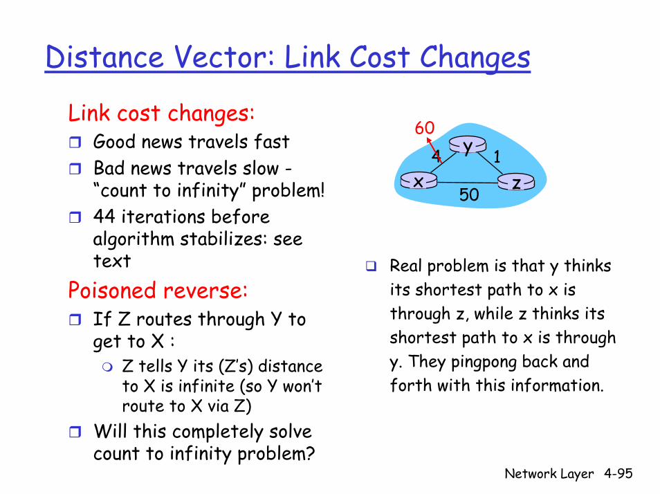
Distance Vector: Link Cost Changes
Link cost changes:Good news travels fast Bad news travels slow -“count to infinity” problem! x z
14
50
y60
44 iterations before algorithm stabilizes: see text
Poisoned reverse:If Z routes through Y to get to X :
Z tells Y its (Z’s) distance to X is infinite (so Y won’t route to X via Z)
Will this completely solve count to infinity problem?
Real problem is that y thinks its shortest path to x is through z, while z thinks its shortest path to x is through y. They pingpong back and forth with this information.
Network Layer 4-96
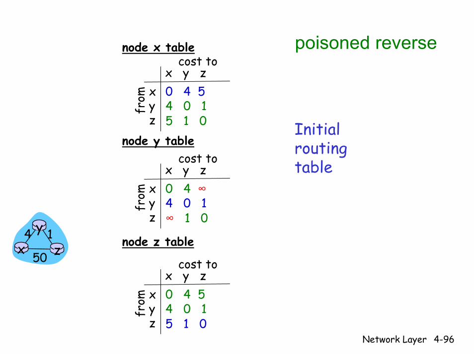
poisoned reverse
xyz
cost tox y z0 4 5
from 4 0 1
5 1 0
node x table
node y table
node z table
xyz
cost tox y z0 4 ∞
from 4 0 1∞ 1 0
xyz
cost tox y z0 4 5
from 4 0 1
5 1 0
Initial routing table
x z14
50
y
Network Layer 4-97
x z14
50
y60
xyz
cost tox y z0 51 50
from 4 0 1
5 1 0
node x table
node y table
node z table
xyz
cost tox y z0 4 ∞
from 60 0 1
∞ 1 0
xyz
cost tox y z0 4 5
from 4 0 1
5 1 0
xyz
cost tox y z0 51 50
from 60 0 1
5 1 0
node x table
node y table
node z table
xyz
cost tox y z0 51 50
from 60 0 1
∞ 1 0
xyz
cost tox y z0 ∞ 50
from 60 0 1
50 1 0
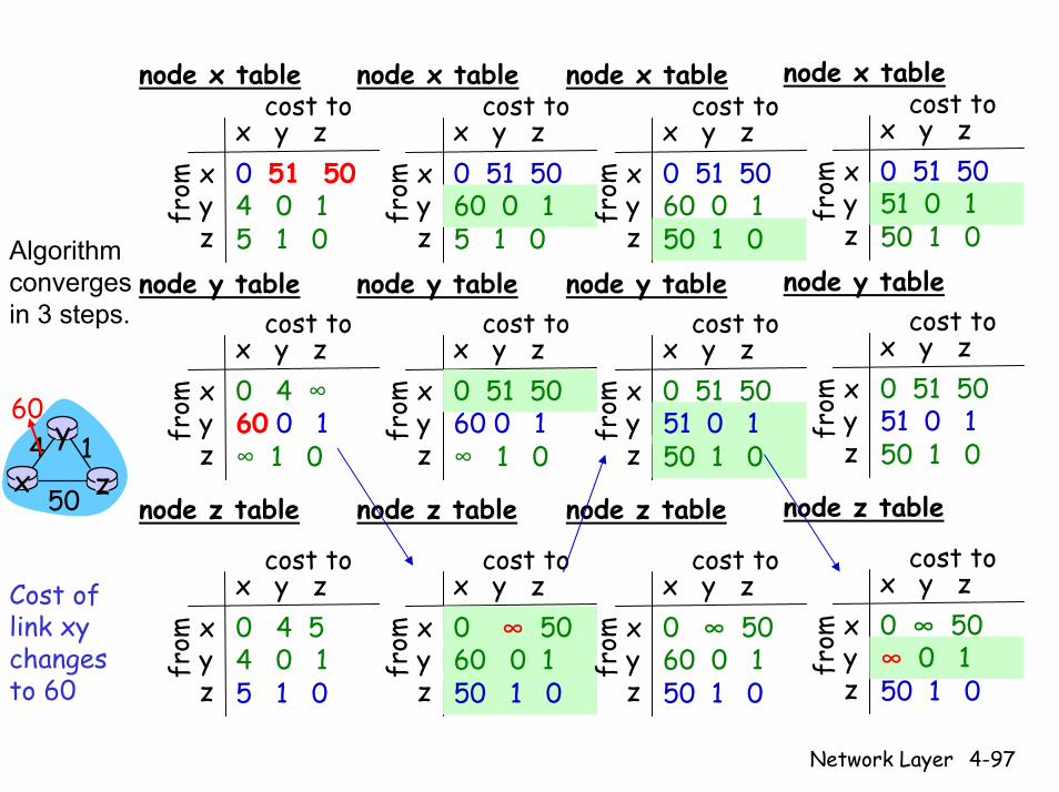
Cost of link xy changes to 60
xyz
cost tox y z0 51 50
from 60 0 1
50 1 0
node x table
node y table
node z table
xyz
cost tox y z0 51 50
from 51 0 1
50 1 0
xyz
cost tox y z0 ∞ 50
from 60 0 1
50 1 0
Algorithm converges in 3 steps.
xyz
cost tox y z0 51 50
from 51 0 1
50 1 0
node x table
node y table
node z table
xyz
cost tox y z0 51 50
from 51 0 1
50 1 0
xyz
cost tox y z0 ∞ 50
from ∞ 0 1
50 1 0

Network Layer 4-98
Comparison of LS and DV algorithms
Robustness: what happens if router malfunctions?
LS:Node can advertise incorrect link costEach node computes only its own table
DV:DV node can advertise incorrect path costEach node’s table used by others
• Error propagate thru network
Message complexityLS: with n nodes, E links, O(nE) msgs sent DV: exchange between neighbors only
Convergence time varies
Speed of ConvergenceLS: O(n2) algorithm requires O(nE) msgs
May have oscillationsDV: convergence time varies
May be routing loopsCount-to-infinity problem

Network Layer 4-99
Chapter 4: Network Layer
4. 1 Introduction4.2 Virtual circuit and datagram networks4.3 What’s inside a router4.4 IP: Internet Protocol
Datagram formatIPv4 addressingICMPIPv6
4.5 Routing algorithmsLink stateDistance VectorHierarchical routing
4.6 Routing in the Internet
RIPOSPFBGP

Network Layer 4-100
Hierarchical Routing
Scale: with 200 million destinations:Can’t store all dest’s in routing tables!Routing table exchange would swamp links!
Our routing study thus far - idealization All routers identicalNetwork “flat”
… not true in practice
Administrative autonomyInternet = network of networksEach network admin may want to control routing in its own network
Network Layer 4-101
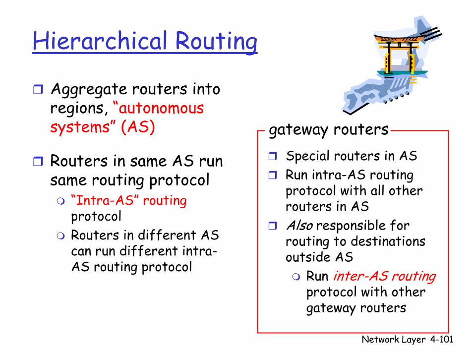
Hierarchical Routing
Special routers in ASRun intra-AS routing protocol with all other routers in ASAlso responsible for routing to destinations outside AS
Run inter-AS routingprotocol with other gateway routers
gateway routers
Aggregate routers into regions, “autonomous systems” (AS)
Routers in same AS run same routing protocol
“Intra-AS” routingprotocolRouters in different AS can run different intra-AS routing protocol
Network Layer 4-102
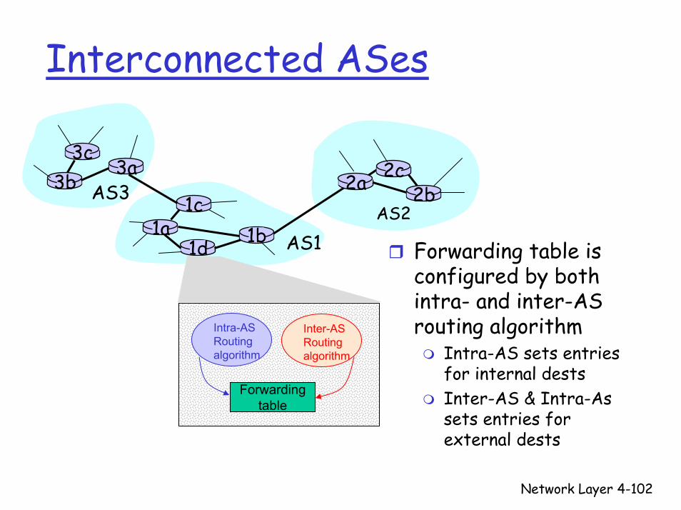
Interconnected ASes
3b
1d
3a
1c2aAS3
AS1AS2
1a
2c2b
1b
3c
Forwarding table is configured by both intra- and inter-AS routing algorithm
Intra-AS sets entries for internal destsInter-AS & Intra-As sets entries for external dests
Intra-ASRouting algorithm
Inter-ASRouting algorithm
Forwardingtable
Network Layer 4-103
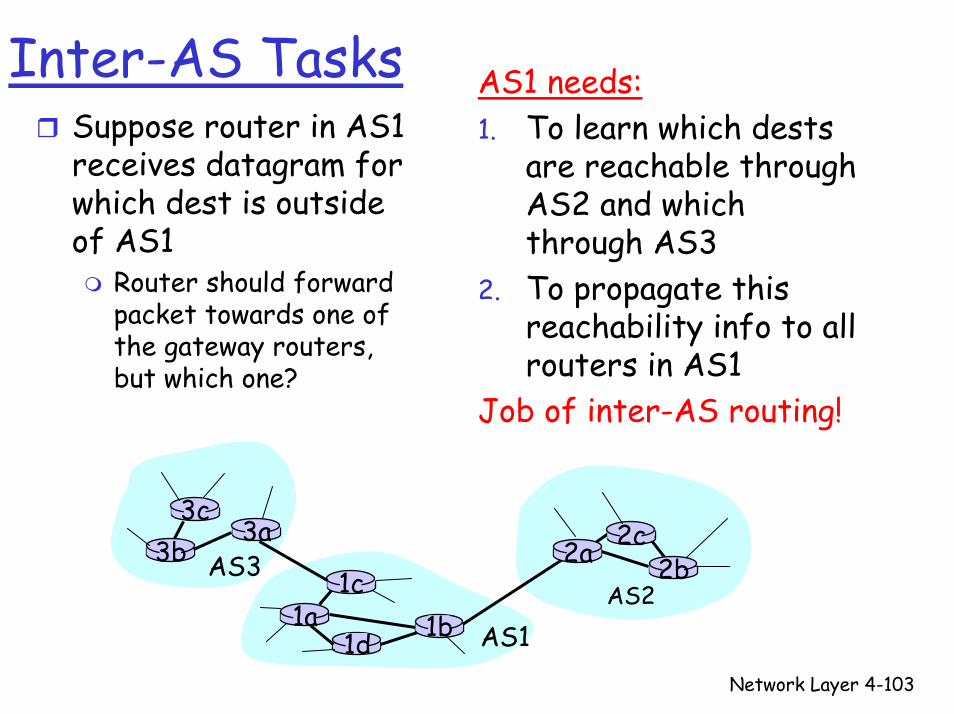
Inter-AS Tasks AS1 needs:Suppose router in AS1 receives datagram for which dest is outside of AS1
Router should forward packet towards one of the gateway routers, but which one?
1. To learn which destsare reachable through AS2 and which through AS3
2. To propagate this reachability info to all routers in AS1
Job of inter-AS routing!
3b
1d
3a
1c2aAS3
AS1AS2
1a
2c2b
1b
3c

Network Layer 4-104
Example: Setting Forwarding Table in Router 1d
Suppose AS1 learns (via inter-AS protocol) that subnet x is reachable via AS3 (gateway 1c) but not via AS2Inter-AS protocol propagates reachability info to all internal routersRouter 1d determines from intra-AS routing info that its interface I is on the least cost path to 1cPuts in forwarding table entry (x,I)
3b
1d
3a
1c2aAS3
AS1AS2
1a
2c2b
1b
3c

Network Layer 4-105
Example: Choosing Among Multiple ASes
Now suppose AS1 learns from the inter-AS protocol that subnet x is reachable from AS3 and from AS2To configure forwarding table, router 1d must determine towards which gateway it should forward packets for dest xThis is also the job on inter-AS routing protocol!Hot potato routing: send packet towards closest of two routers
Learn from inter-AS protocol that subnet x is reachable via multiple gateways
Use routing infofrom intra-AS
protocol to determinecosts of least-cost
paths to eachof the gateways
Hot potato routing:Choose the gateway
that has the smallest least cost
Determine fromforwarding table the interface I that leads
to least-cost gateway. Enter (x,I) in
forwarding table

Network Layer 4-106
Chapter 4: Network Layer
4. 1 Introduction4.2 Virtual circuit and datagram networks4.3 What’s inside a router4.4 IP: Internet Protocol
Datagram formatIPv4 addressingICMPIPv6
4.5 Routing algorithmsLink stateDistance VectorHierarchical routing
4.6 Routing in the Internet
RIPOSPFBGP
Network Layer 4-107
Routing in the InternetThe Global Internet consists of Autonomous Systems (AS) interconnected with each other:
Stub AS: small corporation: one connection to other AS’sMultihomed AS: large corporation (no transit): multiple connections to other AS’sTransit AS: provider, hooking many AS’s together
Two-level routing: Intra-AS: (within AS) administrator responsible for choice of routing algorithm within networkInter-AS: (between ASes) unique standard for inter-AS routing: BGP
Network Layer 4-108
Intra-AS Routing
Also known as Interior Gateway Protocols (IGP)
Most common Intra-AS routing protocols:
RIP: Routing Information Protocol
OSPF: Open Shortest Path First
IGRP: Interior Gateway Routing Protocol (Cisco proprietary)
Network Layer 4-109
Chapter 4: Network Layer
4. 1 Introduction4.2 Virtual circuit and datagram networks4.3 What’s inside a router4.4 IP: Internet Protocol
Datagram formatIPv4 addressingICMPIPv6
4.5 Routing algorithmsLink stateDistance VectorHierarchical routing
4.6 Routing in the Internet
RIPOSPFBGP
Network Layer 4-110
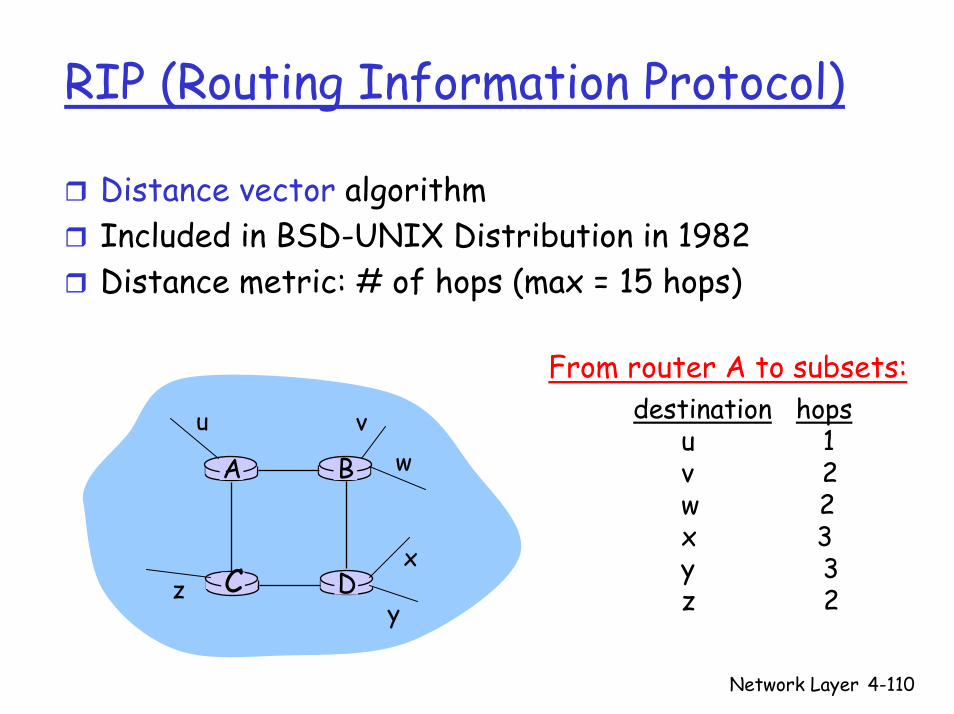
RIP (Routing Information Protocol)
Distance vector algorithmIncluded in BSD-UNIX Distribution in 1982Distance metric: # of hops (max = 15 hops)
DC
BA
u vw
x
yz
destination hopsu 1v 2w 2x 3y 3z 2
From router A to subsets:
Network Layer 4-111
RIP Advertisements
Distance vectors: exchanged among neighbors every 30 sec via Response Message (also called advertisement)Each advertisement: list of up to 25 destination nets within AS

Network Layer 4-112
RIP: Example
w x yz
A
C
D B
Destination Network Next Router Num. of hops to dest.w A 2y B 2z B 7x -- 1…. …. ....
Routing table in D
Network Layer 4-113
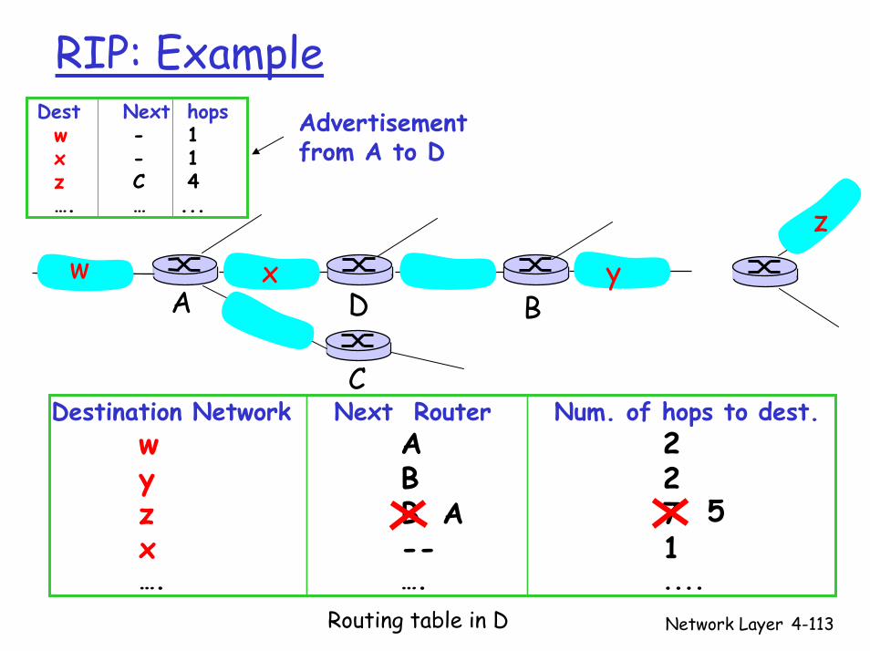
RIP: Example
Destination Network Next Router Num. of hops to dest.w A 2y B 2z B 7x -- 1…. …. ....
w x y
z
A
C
D B
Dest Next hopsw - 1x - 1z C 4…. … ...
Advertisementfrom A to D
A 5
Routing table in D

Network Layer 4-114
RIP: Link Failure and RecoveryIf no advertisement heard after 180 sec -->
neighbor/link declared deadRoutes via neighbor invalidatedNew advertisements sent to neighborsNeighbors in turn send out new advertisements (if tables changed)Link failure info quickly propagates to entire netPoison reverse used to prevent ping-pong loops (infinite distance = 16 hops)

Network Layer 4-115
RIP Table Processing
RIP routing tables managed by application-levelprocess called route-d (daemon)Advertisements sent in UDP packets, periodically repeated
physicallink
network forwarding(IP) table
Transport(UDP)
routed
network(IP)link
physical
Transport(UDP)
routed
forwardingtable

Network Layer 4-116
Chapter 4: Network Layer
4. 1 Introduction4.2 Virtual circuit and datagram networks4.3 What’s inside a router4.4 IP: Internet Protocol
Datagram formatIPv4 addressingICMPIPv6
4.5 Routing algorithmsLink stateDistance VectorHierarchical routing
4.6 Routing in the Internet
RIPOSPFBGP
Network Layer 4-117
OSPF (Open Shortest Path First)
“Open”: publicly availableUses Link State algorithm
LS packet disseminationTopology map at each nodeRoute computation using Dijkstra’s algorithm
OSPF advertisement carries one entry per neighbor routerAdvertisements disseminated to entire AS (via flooding)
Carried in OSPF messages directly over IP (rather than TCP or UDP
Network Layer 4-118
OSPF “Advanced” Features (not in RIP)
Security: all OSPF messages authenticated (to prevent malicious intrusion) Multiple same-cost paths allowed (only one path in RIP)For each link, multiple cost metrics for different TOS (e.g., satellite link cost set “low” for best effort; high for real time)Integrated uni- and multicast support:
Multicast OSPF (MOSPF) uses same topology data base as OSPF
Hierarchical OSPF in large domains
Network Layer 4-119
Hierarchical OSPF
Network Layer 4-120
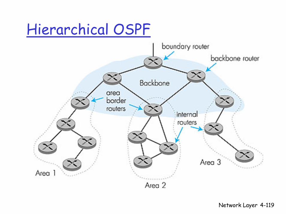
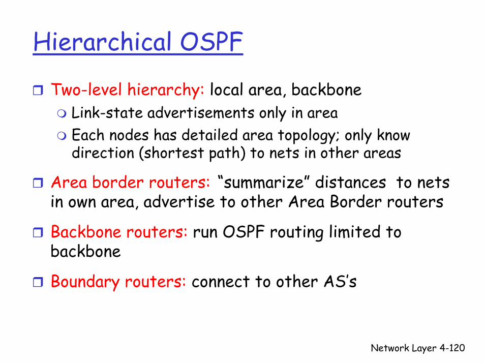
Hierarchical OSPF
Two-level hierarchy: local area, backboneLink-state advertisements only in area Each nodes has detailed area topology; only know direction (shortest path) to nets in other areas
Area border routers: “summarize” distances to nets in own area, advertise to other Area Border routers
Backbone routers: run OSPF routing limited to backbone
Boundary routers: connect to other AS’s
Network Layer 4-121
Chapter 4: Network Layer
4. 1 Introduction4.2 Virtual circuit and datagram networks4.3 What’s inside a router4.4 IP: Internet Protocol
Datagram formatIPv4 addressingICMPIPv6
4.5 Routing algorithmsLink stateDistance VectorHierarchical routing
4.6 Routing in the Internet
RIPOSPFBGP

Network Layer 4-122
Inter-AS Routing in the Internet: BGP
Figure 4.5.2-new2: BGP use for inter-domain routing
AS2 (OSPF
intra-AS routing)
AS1 (RIP intra-AS
routing) BGP
AS3 (OSPF intra-AS
routing)
BGP
R1 R2
R3
R4
R5
Network Layer 4-123
Internet Inter-AS Routing: BGP
BGP (Border Gateway Protocol): the de facto standardBGP provides each AS a means to:1. Obtain subnet reachability information from
neighboring ASs.2. Propagate reachability information to all AS-
internal routers.3. Determine “good” routes to subnets based on
reachability information and policy.Allows subnet to advertise its existence to rest of Internet: “I am here”
Network Layer 4-124
In BGP, destination are not individual hosts, they are networks!
A network is represented by a CIDR prefix, e.g., 138.16.64/24If a gateway router broadcasts a BGP message stating that it is 138.16.64/24, it is advertisingthat it can deliver messages to any host in subnet 138.16.64/24
BGP messages between routers in same AS are called (interior) iBGP messagesBGP messages between routers in diff AS are called (exterior) eBGP messages
Network Layer 4-125
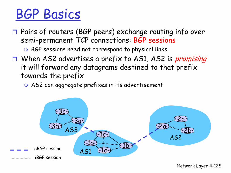
BGP BasicsPairs of routers (BGP peers) exchange routing info over semi-permanent TCP connections: BGP sessions
BGP sessions need not correspond to physical linksWhen AS2 advertises a prefix to AS1, AS2 is promisingit will forward any datagrams destined to that prefix towards the prefix
AS2 can aggregate prefixes in its advertisement
3b
1d
3a
1c2aAS3
AS1
AS21a
2c
2b
1b
3c
eBGP session
iBGP session
Network Layer 4-126
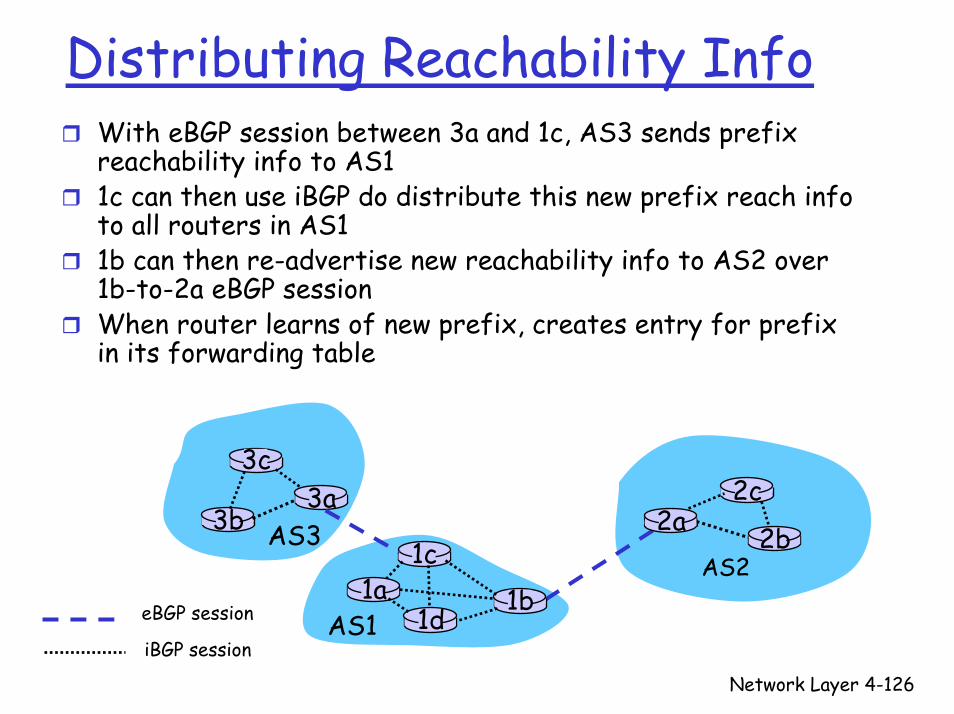
Distributing Reachability InfoWith eBGP session between 3a and 1c, AS3 sends prefix reachability info to AS11c can then use iBGP do distribute this new prefix reach info to all routers in AS11b can then re-advertise new reachability info to AS2 over 1b-to-2a eBGP sessionWhen router learns of new prefix, creates entry for prefix in its forwarding table
3b
1d
3a
1c2aAS3
AS1
AS21a
2c
2b
1b
3c
eBGP session
iBGP session
Network Layer 4-127
Path Attributes & BGP Routes
When advertising a prefix, advert includes BGP attributes.
prefix + attributes = “route”Two important attributes:
AS-PATH: contains ASs through which prefix advertisement has passed: AS 67 AS 17 NEXT-HOP: Indicates specific internal-AS router to next-hop AS. (There may be multiple links from current AS to next-hop-AS.)
When gateway router receives route advertisement, uses import policy to accept/decline

Network Layer 4-128
BGP Route Selection
Router may learn about more than 1 route to some prefix. Router must select route
Elimination rules:1. Local preference value attribute: policy
decision2. Shortest AS-PATH 3. Closest NEXT-HOP router: hot potato routing4. Additional criteria
Network Layer 4-129
BGP Messages
BGP messages exchanged using TCPBGP messages:
OPEN: opens TCP connection to peer and authenticates senderUPDATE: advertises new path (or withdraws old)KEEPALIVE keeps connection alive in absence of UPDATES; also ACKs OPEN requestNOTIFICATION: reports errors in previous msg; also used to close connection

Network Layer 4-130
BGP Routing Policy
Figure 4.5-BGPnew: a simple BGP scenario
A
B
C
W X
Y
legend:
customer network:
provider network
A,B,C are provider networksX,W,Y are customer (of provider networks)X is dual-homed: attached to two networks
X does not want to route from B via X to C.. so X will not advertise to B a route to C

Network Layer 4-131
BGP Routing Policy (2)
Figure 4.5-BGPnew: a simple BGP scenario
A
B
C
W X
Y
legend:
customer network:
provider network
A advertises to B the path AW B advertises to X the path BAW Should B advertise to C the path BAW?
No way! B gets no “revenue” for routing CBAW since neither W nor C are B’s customers B wants to force C to route to w via AB wants to route only to/from its customers!
Network Layer 4-132
Why different Intra- and Inter-AS routing ?
Policy:Inter-AS: admin wants control over how its traffic routed, who routes through its net. Intra-AS: single admin, so no policy decisions needed
Scale:Hierarchical routing saves table size, reduced update traffic
Performance:Intra-AS: can focus on performanceInter-AS: policy may dominate over performance
Network Layer 4-133
Network Layer: SummaryWhat we’ve covered:
Network layer servicesRouting principles: link state and distance vectorHierarchical routingIPInternet routing protocols RIP, OSPF, BGPWhat’s inside a router?IPv6
Next stop:the Datalink layer!