Trans-Pacific Partnership Chapter 13. Telecommunications Chapter
Chapter 4 Galileo Telecommunications
Jim Taylor Kar-Ming Cheung and Dongae Seo
41 Mission and Spacecraft Description This chapter describes how the Galileo orbiter received and transmitted data with the Deep Space Network (DSN) The relay communications subsystems and the link between the Galileo probe and the orbiter are also described briefly The chapter is at a functional level intended to illuminate the unique mission requirements and constraints that led to both design of the communications system and how the mission had to be modified and operated in flight
Augmenting the spacecraft downlink design and the supporting ground system for science return with only the low-gain antenna (LGA) was a particular challenge for the Galileo planetary mission
The Galileo orbiter was designed and built at the Jet Propulsion Laboratory (JPL) in Pasadena California and the Galileo probe was designed and built at the NASA Ames Research Center (ARC) in Sunnyvale California The orbiter flight team was located at JPL as was the probe flight team during that portion of the mission
411 The Mission The Galileo spacecraft was launched in 1989 aboard the Space Shuttle Atlantis (STS [Space Transportation System]-34) Its primary objective was to study the Jovian System The Galileo launch delay after the Challenger Space Shuttle
81
82 Chapter 4
accident in 1986 necessitated a change in the strategy to get Galileo to Jupiter1
The original strategy was a relatively direct flight to Jupiter with a single gravity assist at Mars The new mission plan had to work with less propulsion so it made use of a longer much less direct flight with gravitational assists from Venus once and Earth twice to give the spacecraft enough energy to get to Jupiter During the cruise phase of the mission2 the Galileo spacecraft took the first close-up images of an asteroid (Gaspra) in October 1991 and discovered the first known moon (Dactyl) of an asteroid (Ida) in August 1993 [2] During the latter part of the cruise Galileo was used to observe the collisions of fragments of Comet Shoemaker-Levy 9 with Jupiter in July 1994
The Galileo primary mission (1995ndash1997) involved
Penetration of Jupiterrsquos atmosphere by the probe that returned a Jovian ldquoweather reportrdquo on temperature pressure composition winds clouds and lightning
Initial orbiter flyby of the Jovian satellite Io and passage through the Io torus
Jupiter orbit insertion (JOI) A two-year ldquotourrdquo of the major satellites by the orbiter that returned
images radio science and data on fields and particles
The probe descended through an unusually dry spot in Jupiterrsquos top cloudy layer and probably melted in the hot atmosphere somewhere below the clouds
The orbiter had six scientific instruments on one section that spun (at 3 revolutions per minute rpm) for pointing stability and for collecting three-dimensional fields and particles data near the spacecraft The ldquode-spunrdquo section used gyros to point the four remote-sensing instruments at a target to obtain images composition surface structure and temperature data3 The orbiterrsquos umbrella-like high-gain antenna (HGA) did not deploy so Galileorsquos computer was reprogrammed to compress and record the data taken during Jovian satellite flybys to the on-board tape recorder The data was returned to Earth
1 The last planetary launch before Galileo in 1989 was Pioneer Venus in 1978 Galileo remained in ldquonew missionrdquo status for these years while the launch vehicle was changed four times Each change none of them due to the Galileo spacecraft itself necessitated a complete redesign of the mission with corresponding changes to the requirements for tracking and data acquisition support by the DSN [1]
2 Refer to httpsolarsystemnasagovgalileomissionjourney-cruisecfm [3] for more on the Galileo interplanetary mission design (accessed January 10 2013)
3 The last remote sensing data from the orbiter was received in March 2002
83 Galileo Telecommunications
during the remainder of each orbit using the low-gain antenna (LGA) and modifications to the ground receiving systems of the Deep Space Network (DSN)
The orbiter was powered by two radioisotope-thermoelectric-generators (RTGs) It used its 400 newton (N) main engine to go into Jupiter orbit but maintained pointing and fine-tuning of each new orbit with clusters of 10-N thrusters
The prime-mission tour consisted of 11 different elliptical orbits around Jupiter with each orbit (except one) involving a close flyby and gravity assist at Jupiterrsquos moons Ganymede Callisto or Europa The major scientific returns from the primary mission included data on
Jupiterrsquos storms and rings Hot active volcanoes on Io Strong evidence for a possible ocean on Europa Ganymedersquos own magnetic field Evidence suggesting the possibility of liquid saltwater oceans beneath
the surfaces of Ganymede and Callisto surface
After completing its primary mission Galileo began a two-year extended mission called the Galileo Europa Mission (GEM) on December 8 1997 GEM was a 14-orbit low-cost extension of Galileorsquos exploration of the Jovian system This mission was divided into three main phases
The Europa Campaign (December 1997ndashMay 1999) which searched for further signs of a past or present ocean beneath Europarsquos icy surface
The Jupiter WaterIo Torus Study (May 1999ndashOctober 1999) which focused on detailed storm and wind patterns in Jupiterrsquos atmosphere and
The Io Campaign (October 1999ndashDecember 1999) which obtained from two flybys high-resolution images and a compositional map of Io with a sample of a volcanic plume
At the end of the GEM December 31 1999 the orbiter started another mission called the Galileo Millennium Mission (GMM) This mission originally was planned for completion within approximately 14 months but was extended to 2003 The GMM mission plan originally consisted of two phases the first named Io and the second Cassini4 The 2003 mission extension included plans
4 For more on the GalileoCassini 2001ndash2002 cooperative mission refer to httpwwwjplnasagovjupiterflyby and to
84 Chapter 4
for the final disposition of the orbiter5 During the GMM the orbiter made additional close flybys of all four large moons including four encounters of Io from 2000 through 2002 The spacecraft studied Iorsquos extensive volcanic activity and the magnetic environment at high resolution It also observed Europarsquos ionosphere generated by ultraviolet radiation from the Sun and interaction of the charged particles from the Jovian magnetosphere In the Cassini phase the spacecraft performed cooperative measurements with the Cassini spacecraft as Cassini received its own gravity assist from Jupiter in December 2000 Galileo was also relatively near Jupiter at that time Galileo collected data from Jupiters inner magnetosphere the dusk side of the magnetosphere and the solar wind
In November 2002 Galileorsquos orbit took it closer to Jupiter than ever before flying less than 1000 kilometers (km) over the moon Amalthea6 which is less than one-tenth the size of Io and less than half as far from Jupiter Measurements of changes in Galileorsquos radio signal frequencies during the flyby were used refine the mass and density of Amalthea This passage produced information on dust particles as Galileo flew through Jupiterrsquos gossamer rings as well as new information on magnetic forces and energetic charged particles close to the planet Galileorsquos final orbit took an elongated loop away from Jupiter Then on September 21 2003 came an intentional mission-ending plunge into Jupiterrsquos atmosphere to ensure against the possibility of impact and Earthly contamination of any Jovian satellites Eight years after probe entry the orbiter also made a direct impact with Jupiter vaporizing as it plowed into the dense atmosphere
Figure 4-1 is a graphical representation of the sizes and orientations of the orbits around Jupiter for the prime mission and the GEM [432] For clarity only some of the orbits are labeled with the alphabetic character indicating the targeted Jovian satellite (Callisto Ganymede Europa or Io) for that orbit and the two-digit number representing the orbit number
httpsaturnjplnasagovnewsnewsreleasesnewsrelease20010329 (both accessed January 10 2013)
5 Refer to httpwwwjplnasagovnewsfact_sheetsgalileo0309pdf [5] for more information on the current GMM and a table showing the dates and flyby altitudes of all of Galileorsquos satellite encounters (accessed January 10 2013)
6 Amalthea averages 189 km in diameter (270 166 150) Amalthea was the nymph who nursed the infant Zeus with goatrsquos milk in Greek mythology
httpenwikipediaorgwikiAmalthea_28moon29 (accessed January 10 2013)
85 Galileo Telecommunications
Fig 4-1 Galileo Europa mission and prime mission tours
412 The Spacecraft The Galileo spacecraft (Fig 4-2) had two main components at launch the 62-meter (m) tall orbiter and the 09-m long probe7 The orbiterrsquos launch mass was 2223 kilograms (kg) including a 118-kg science payload and 925 kg of usable propellant8 The probersquos total mass was 339 kg the probe descent module was 121 kg including a 30-kg science payload
4121 Galileo Orbiter The Galileo orbiter combined features of spinner spacecraft (the Pioneers and Ulysses) and three-axis-stabilized spacecraft (the Voyagers) The orbiter incorporated an innovative ldquodual-spinrdquo design Part of the orbiter (including the telecom electronics and antennas and some instrument
7 Figure 4-1 and Figure 4-2 come from predecessors to
httpsolarsystemnasagovgalileomissionjourney-orbitalcfm
httpsolarsystemnasagovgalileomissionspacecraftcfm
These are links to the Galileo legacy website [3] that includes brief descriptions of the Galileo mission spacecraft (orbiter and probe) and mission operations (accessed January 10 2013)
8 Propellant made up 41 percent of the orbiterrsquos launch mass Most of the propellant was consumed at JOI
86 Chapter 4
Fig 4-2 Galileo spacecraft
booms) rotated while another part (containing an instrument platform) remained fixed in inertial space The orbiter was a good platform for fields and particles experiments that perform best when rapidly gathering data from different directions The orbiter was also a good platform for remote sensing experiments that require accurate and steady pointing
The orbiter used two RTGs to supply electrical power to run the spacecraftrsquos devices The radioactive decay of plutonium produced heat that was converted to electricity The RTGs produced about 570 watts (W) at launch The power output decreased at the rate of 06 W per month and was 493 W when Galileo arrived at Jupiter
The attitude and articulation control subsystem (AACS) was responsible for determining the orientation of the spacecraft in inertial space keeping track of the spacecraft orientation between attitude determinations and changing the orientation instrument pointing spin rate or wobble of the spacecraft Software in the AACS computer performed the calculations necessary to do these functions As part of the S-band (2 to 4 gigahertz GHz) mission (described in Section 44 of this chapter) the AACS software was updated to include the ability to compress imaging and plasma wave data down to as little as 180th of their original volume
Galileo Telecommunications 87
There were 12 scientific experiments aboard the Galileo orbiter The despun section was home to four remote-sensing instruments (labeled in red in Fig 4-2) mounted on the scan platform with their optical axes aligned so that they viewed a nearly common area The spun section contained six instruments (labeled in blue) to investigate particles and magnetic fields Two radio-science investigations (celestial mechanics and radio propagation) did not have individual instruments but piggybacked on the orbiterrsquos telecom system including the systemrsquos ultrastable oscillator (USO)
Figure 4-3 shows the wavelength ranges of the electromagnetic spectrum that the remote-sensing instruments monitored during both encounters and cruise periods
4122 Galileo Probe The probe consisted of two main parts the deceleration module and the descent module9 The deceleration module was required for the transition from the vacuum and cold of interplanetary space to the intense heat and structural loads incurred during a hypersonic entry into a planetary atmospheremdashand from a speed of tens of kilometers per second to a relatively placid descent by parachute The descent module carried the scientific instruments and supporting engineering subsystems that collected and transmitted scientific data to the orbiter which was flying overhead
Fig 4-3 Galileo orbiterrsquos remote sensing instrument wavelength ranges
in the electromagnetic spectrum
9 The probe description comes from
httpsolarsystemnasagovgalileomissionjourney-probecfm [3] (accessed January 10 2013)
See Section 46 of this chapter for more detail on the probe-to-orbiter relay link
88 Chapter 4
The probe did not have an engine or thrusters so it could not change the path set for it by the orbiter at separation The probe was spin-stabilized achieved by spinning the orbiter up to 105 rpm before release There was no communication between orbiter and probe during the coast to Jupiter because the probe had no capability to receive radio signals During atmospheric entry the probe stored no data collecting and transmitting it in real time
The probersquos entry into the Jovian atmosphere generated temperatures of 14000 K The materials used for the probersquos descent module heat shieldsmdash carbon phenolic for the forebody shield and phenolic nylon for the afterbody shieldmdashhave also been used for Earth re-entry vehicles
Parachutes were used for two key functions separating the deceleration and descent modules and providing an appropriate rate of descent through the atmosphere Before deployment of the main chute a smaller pilot parachute was fired at 30 meters per second (ms) by a mortar to start the deployment process The deployment occurred in less than 2 s pulling away the aft cover and unfurling the main chute The main parachutersquos diameter was 25 m The canopy and lines were made of Dacron and Kevlar respectively Once the main chute was fully deployed the forebody shield (aeroshell) was jettisoned
To save weight the Galileo descent module carrying six scientific instruments was not sealed against the influx of the Jovian atmosphere However the two relay radio systems were hermetically sealed within housings designed to withstand pressures up to 20 bars and tested to 16 bars (2 and 16 megapascals MPa)
42 Galileo Spacecraft Telecommunications System The Galileo telecommunications system (Fig 4-4) was on the spun section of the dual-spin orbiter The system consists of four hardware subsystems
1) Radio frequency subsystem (RFS) 2) Modulation demodulation subsystem (MDS) 3) S-X-band10 antenna (SXA) subsystem 4) X- to S-band downconverter (XSDC)
10 For Galileo S-band refers to carrier frequencies of about 21 GHz (uplink) and 23 GHz (downlink) X-band refers to carrier frequencies of about 72 GHz (uplink) and 84 GHz (downlink)
89 Galileo Telecommunications
Fig 4-4 Galileo orbiter telecom system
421 Galileo Telecommunications Functions and Modes The Galileo telecommunications system11 enabled the orbiter to provide (a) uplink carrier tracking and downlink carrier generation (b) command detection (c) telemetry encoding and modulation and (d) radiometric communications with the Deep Space Network (DSN)12 For interplanetary cruise Galileo originally planned to use a ground station operated by the
11 Sections 32 and 33 describe the Galileo orbiter telecom system and the ground system as they were originally intended for use The orbiter no longer exists and the ground system has evolved away from S-band References to uplink or downlink at X-band assume the availability of a fully deployed high-gain antenna (HGA) As described in Section 44 the HGA did not deploy The X-band parts of the RFS were verified operational in short tests in 1991 and 1993 The S-band parts of the telecom system that used the LGA functioned as designed
12 The terms ldquoradiometric communicationsrdquo or radiometric data in this article refer collectively to one-way or two-way Doppler turnaround (sequential) ranging and differential one-way ranging (DOR)
90 Chapter 4
German Space Operations Center (GSOC)13 as well as those of the DSN During the prime mission antenna arrays included the Parkes antenna operated by the Australian Commonwealth Scientific and Industrial Research Organization (CSIRO)14
4211 Uplink Depending on the required uplink mode the carrier could be unmodulated modulated with a command subcarrier or ranging modulation or both
42111 Uplink Carrier The spacecraft receiver could acquire an uplink carrier arriving close enough in frequency and then maintain phase-lock on that carrier as long as it was present The telecom system was able to operate in the following uplink modes
With an uplink or with no uplink With the uplink at S-band or at X-band With the uplink modulated or unmodulated With the uplink transmitted from the either the DSN or GSOC
42112 Command Detection The RFS S-band receiver (S-RCVR) and the command detector unit (CDU) received and demodulated the command waveform from either an S-band or an X-band uplink carrier and send it to the hardware command decoder in the command data subsystem (CDS) The command waveform could be present alone or simultaneously with ranging modulation
4212 Downlink The downlink carrier could be unmodulated modulated with a telemetry subcarrier or ranging modulation or both
42121 Downlink Carrier The RFS exciters (EXC) and power amplifiers made up the transmitters that gave the orbiter the capability to generate modulate and transmit downlink carriers With or without an uplink carrier present the RFS was able to generate and transmit an S band downlink carrier alone an X-band downlink carrier alone or both simultaneously With either an S-band or X-band uplink carrier present the RFS had the capability to use the uplink carrier to generate downlink S-band or X-band carrier frequencies or both The S-band and X band downlink carriers were always coherent with each
13 Current information about GSOC is available at
httpwwwdlrdeissendesktopdefaultaspxtabid-14122072_read-3536 14 Current information about the Parkes antenna is available at
httpwwwatnfcsiroau (both links accessed January 10 2013)
91 Galileo Telecommunications
other Depending on RFS mode the downlink carriers both were coherent with the uplink carrier or both were noncoherent15
42122 Telemetry Encoding and Modulation The MDSrsquos telemetry modulation unit (TMU) and the RFSrsquos S-band exciter (S-EXC) and X-band exciter (X-EXC) processed the telemetry ldquolow raterdquo and ldquohigh-raterdquo data-bit streams16 from the CDS into modulated telemetry subcarriers that phase modulated the downlink carriers The TMU provided two telemetry modes Tracking and Data Relay Satellite System (TDRSS)17 and DSN
4213 Radiometric Data Radiometric communications are those that are required of the telecom system to meet project navigation and radio science data quantity and accuracy requirements Radiometric data used with Galileo included two-way or one-way Doppler turnaround ranging and differential one-way ranging (DOR)
4214 Probe Relay The L-band18 relay link from the probe to the orbiter active for about one hour on December 7 1995 used equipment entirely separate from the orbiterrsquos S-band and X-band uplink and downlink Section 46 describes the relay link and its telecom-related results in more detail
The orbiter-mounted relay receiving hardware (RRH) received the L-band signal from the probe Though mounted on and in the orbiter the RRH antenna and receivers were designated part of the probe system To eliminate singleshy
15 Galileo was one of many JPL deep-space missions having two downlink modes called ldquoTWNC onrdquo and ldquoTWNC offrdquo TWNC (two-way non-coherent) is pronounced ldquotwinkrdquo The TWNC-on mode means the downlink frequency cannot be coherent with an uplink frequency The TWNC-off mode means the downlink will be coherent with a received uplink when the transponderrsquos receiver is in lock to the uplink carrier
16 As more fully described in Section 423 the CDS continuously output to the TMU both a 40 bits-per-second (bps) low-rate data stream and a high-rate data stream The bit rate of the high-rate stream was set between 10 bps and 1344 kbps so in most cases its bit rate was higher than the fixed 40 bps of the low-rate channel
17 In the TDRSS mode the TMU convolutionally coded a 1200-bps data stream received from the CDS The symbol stream phase-modulated the RFS S-band RF carrier at 90plusmn3 deg without use of a telemetry subcarrier This mode was used only for the immediate post-launch phase while the spacecraft was still attached to the Inertial Upper Stage (IUS) See 35 Telecom Operational Scenarios in this chapter
18 L-band refers to frequencies between 390 megahertz (MHz) and 1550 MHz The probe-to-orbiter relay link carriers were 13870 MHz and 13871 MHz chosen to provide the best link performance through Jupiterrsquos atmosphere
92 Chapter 4
point catastrophic mission failures the relay link system configuration included two nearly identical RF links with dual electrical and electronic probe transmitting and orbiter receiving systems Two parallel and simultaneous data streams went from the probersquos scientific instruments to the orbiter One of the data streams used a USO for transmission to the orbiter The probe Doppler wind experiment used variations in the frequencies of the carrier signals received at the orbiter to deduce the wind speeds in the atmosphere [6]
422 Radio Frequency Subsystem The RFS had the major components listed in Table 4-1 The table includes the subsystem acronyms for reference
Table 4-1 RFS components
Element Number of Units S-band receiver (S-RCVR) 2 S-band exciter (S-EXC) 2 X-band exciter (X-EXC) 2 Ultrastable oscillator (USO) 1 S-band traveling-wave-tube amplifier (S-TWTA) 2 X-band traveling-wave-tube amplifier (X-TWTA) 2 Differential one-way ranging (DOR) generator 1 S-band antenna switches (LGA-1LGA-2 switches HGALGA switch) 21 Microwave routing and interface elements NA
Where there were duplicated units in a pair (such as S-RCVRs) generally each could provide full functionality The units were cross-strapped but with only one unit powered at a time19 For example either S-RCVR could drive either SshyEXC with the powered receiver driving the powered exciter Similarly either S-EXC could drive either S-TWTA Additional functional redundancy was built into the RFS in the sense that the 1-way downlink frequency source could be either the exciterrsquos auxiliary oscillator or the USO and (when using the HGA) the downlink could be at either S-band or X-band
19 The term ldquocross-strappedrdquo refers to the interconnections at the unit input or output Because RCVR-1 and RCVR-2 were cross-strapped with S-EXC-1 and S-EXC-2 the transponder could operate with RCVR-1 driving either S-EXC-1 or S-EXC-2 or RCVR-2 driving either S-EXC ldquoGenerallyrdquo means there were exceptions required either in hardware design or flight rule or a factor in selecting configuration [5] RFS exceptions to ldquogenerallyrdquo Only RCVR-1 was connected to the XSDC RCVR-2 operated on the same channel as the USO so potential frequency interference was one factor in launching with RCVR-1 selected and the XSDC received too much noise when X-TWTA-2 was on so the two could not operate together
93 Galileo Telecommunications
423 Modulation Demodulation Subsystem The MDS consisted of two TMUs and two CDUs with one CDU and one TMU powered at a time The CDU was responsible for the detection (demodulation) of uplink command data for decoding by the CDS and the TMU was responsible for the modulation of telemetry data for downlink transmission
Because of the critical functions performed by the CDU and TMU each had a large amount of hardware redundancy and cross-strapping with the interfacing RFS elements The two CDUs were identical to each other and the two TMUs were nearly identical to each other20 The TMU and the RFS exciter were fully cross-strapped Likewise the CDU pair was cross-strapped with the RFS receiver pair and with the hardware command decoder of the CDS
The TMU received two serial data streams from the telemetry formatter of the CDS The use of the uncoded 40-bps low-rate data was reserved for when the spacecraft entered safing The 10-bps to 1344-kbps high-rate stream was convolutionally encoded21 by the TMU The TMU could modulate either the low-rate bit stream or the high-rate symbol stream on either a 225-kHz subcarrier or a 360-kHz subcarrier from an internal TMU oscillator TMU-B could provide the symbol stream directly to the exciter (TDRSS mode)
The CDU received a modulated 16-kHz command subcarrier from the RFS receiver Depending on the ground station command mode the subcarrier could be unmodulated modulated with a bit-synchronization (bit-sync) waveform equivalent to an all-zeroes command data stream or with both bit-sync and
20 The TMUs were almost identical They differed as follows TMU-A had an experimental ldquocoder-2rdquo that could produce a (1514) convolutional code for 1152 kbps and 1344 kbps and modulate the coder-2 symbols on a 720 kbps subcarrier TMU-B had a ldquoTDRSS moderdquo wherein symbols from the (712) coder directly modulated the S-band carrier (no subcarrier) Adding the experimental coder less than 2 years before launch was a result of the delay in launch date from 1982 to 1989 and consequently the prime mission period to 1995ndash1997 The decrease in output from the already-fueled RTG power supply during the delay meant the TWTA would likely operate only in the low-power mode Part of the communications shortfall was to be made up by using the more efficient (1514) code the remainder by planning an array of the DSNrsquos 70-m antenna with the Very Large Array (VLA) radio science antenna system in New Mexico for the critical encounter data [1] See Ref [7] for a description of the VLA and [8] for the use of the VLA as an arrayed antenna resource during the Voyager mission
21 See Section 43 Galileo S-band Mission for a description of the ldquoconcatenated codingrdquo used from 1996 until the end of the mission
94 Chapter 4
command bits The CDU demodulated the command subcarrier It provided three separate outputs to the CDS command decoder
1) A CDU in-lock or out-of-lock indicator 2) The 32-bps command-bit timing (ldquoclockrdquo) 3) The command bits
424 S-X-Band Antenna Subsystem The SXA consisted of an HGA22 and two LGAs (LGA-1 and LGA-2) The two LGAs only worked at S band The HGA was designed to work at S-band and X-band Because the LGAs had no X-band capability uplink or downlink at X-band required the HGA The spacecraft could be configured (via real time or sequenced commands) to receive and transmit S band on the HGA on LGA-1 or on LGA-2 The same antenna had to be used for both reception and transmission of S-band at a given time Galileo S-band antennas were right circularly polarized (RCP) simplifying the task of configuring the DSN The X-band downlink polarization was RCP or left circularly polarized (LCP) depending which of the X-TWTAs was powered on
The S-band antennas operate at a nominal uplink frequency of 2115 megahertz (MHz) and a nominal downlink frequency of 2295 MHz The actual frequencies were DSN channel 18 for RFS receiver 1 (and for a two-way coherent downlink with that receiver) and channel 14 for RFS receiver 2 (and its coherent downlink) or a USO-generated downlink [5]
Because the most prominent part of the HGA was a main reflector 48 m in diameter it looked like a single antenna However the HGA had two separate feed systems one for S-band and the other for X-band In its functions the HGA could in many ways be considered as two distinct antennas (S-HGA and X-HGA) The X-band and S-band boresights (direction of maximum gain) were co-aligned in the direction of the LGA-1 boresight which was the ndashz axis
Though this was not the original plan LGA-1 was selected for most of the mission LGA-2 with its boresight aligned in the opposite direction from the LGA-1 boresight was only used at specific times when the trajectory geometry required Venus flyby and Earth-1 flyby (see Section 35 Operational Scenarios of the Voyager Interstellar Mission)
22 The Galileo HGA did not deploy fully and therefore was never functional for use in the mission The antenna description in Section 424 is of the system as built and intended for use See Section 43 Galileo S-Band Mission for the workarounds developed during flight to enable a successful mission
95 Galileo Telecommunications
In addition to LGA-1 LGA-2 and HGA the orbiter also had two other antennas that were not considered parts of the orbiter telecom system These were the relay receiving antenna (RRA) for the Galileo probe-to-orbiter relay link and the plasma wave spectrometer (PWS) antenna part of a science instrument
425 X- to S-Band Downconverter The Galileo project always considered the orbiterrsquos single XSDC as an experimental subsystem meaning that use of an X-band uplink was not essential for receiving commands or other critical mission functions The XSDC parts were
Downconverter S-band coupler X-band diplexer Low pass filter Voltage-controlled oscillator (VCO) coupler
The X-band diplexer allowed simultaneous X-band reception (via the XSDC) and transmission (via the X-band TWTA) through the HGA The S-band coupler connected the down-converted X-band modulated carrier to RFS S-RCVR-1 Working with the RFS receiver and transmitter and depending on the controlled configuration the XSDC provided the telecom system with non-coherent or two-way coherent carrier operating modes with an X-band uplink
426 Telecom Hardware Performance during Flight The orbiter was launched with the following elements active S-RCVR-1 S-EXC-1 S-TWTA-1 CDU-A and TMU-A The USO was turned on a few weeks after launch As of the end of the Galileo primary and extended missions these originally selected telecom units were all still selected and generally operating without a problem
The telecom hardware problems that occurred during flight were
HGA failure to deploy (discussed separately in Sections 34 and 36) RFS receiver ldquowandering VCO anomalyrdquo Unexpected CDU lock-count changes USO frequency drift rate changed by radiation
4261 ldquoWandering VCOrdquo RFS Receiver Incident Several days after Ganymede-2 the second of the 10 Jovian satellite encounters of the prime mission the orbiter receiver failed to acquire a routine uplink from the Madrid
96 Chapter 4
tracking station on September 11 199623 The spacecraft turned 90 degrees (deg) off Earth and back several hours before the incident However this change in geometry could not be confirmed as a contributing factor in the subsequently modeled hardware problem Examination of the VCO volts telemetry by telecom showed the measurement had deviated by as much as 8 kHz and +24 kHz from best lock prior to the acquisition attempt [9] The station acquired the uplink using a resweep frequency range 25 times as wide as standard Over the next several days tracking stations had to use sweep frequency ranges as much as 75 times the standard
The receiver returned to normal operation after a radio frequency subsystem tracking-loop capacitor (RFSTLC) test RFSTLC tests conducted periodically through the prime mission required a station to sweep its transmitter in frequency to pull the VCO to either +65 kHz or 65 kHz from the best-lock frequency (BLF) then to turn the transmitter off The VCO frequency then relaxed back to BLF the time it took to do so provided a measure of the time constant of the resistor-capacitor network in the tracking loop In the first RFSTLC test after the incident the frequency-change-vs-time signature and the loop time constant were not normal However the VCO wandering stopped and subsequent RFSTLC tests were normal in all respects This receiver operated normally through the remainder of the prime and extended missions
Ground testing and analysis focused on the receiver tracking-loop integrator an LM108 operational amplifier A model [10] that involves ionic contamination by sodium ions (Na+) fits the inflight data well including the evident self-healing (ldquoannealingrdquo) No further on-board receiver problems occurred
4262 Unexpected CDU Lock-Count Changes As part of its normal operation the CDU incremented a software counter each time it changed to or from out-of-lock to subcarrier-lock or subcarrier-lock to bit-sync-lock The spacecraft telemetered the count as engineering data periodically The CDU passed command data to the command decoder in the CDS only when it was in bit-sync lock The number of lock counts for each session of planned commanding was known If the count exceeded the predicted number this was defined as an ldquounexpected CDUCDS lock-count changerdquo These unexpected lock counts have also occurred on Voyager and other projects and they have
23 A Galileo uplink acquisition required the station to turn on its 100-kW S-band transmitter and perform a frequency sweep A standard sweep varied the frequency at a specified rate over a range of plusmn12 kHz about a center frequency returning to the center frequency for the rest of the pass Even with Doppler over a pass this center frequency reached the spacecraft near enough to the ldquobest lock frequencyrdquo the frequency at which the receiver VCO oscillated without an uplink
97 Galileo Telecommunications
never caused any problem with commanding The several unexpected lock-change events per year on Galileo placed no restrictions on commanding activities With greatly reduced engineering telemetry sample rates and telecom staffing in GEM and GMM unexpected lock-count events were no longer analyzed though they presumably still occurred There was no evidence of any change in receiver or CDU command performance after launch
On Galileo prime-mission unexpected lock counts occurred from a variety of station configuration and operational problems [10] Also one repeatable spacecraft cause is known having been verified in ground tests of a Galileo receiver and CDU in the early 1990s During the test one pair of lock changes occurred as a result of the combination of (a) the uplink tuning rate at the initial uplink acquisition by the unmodulated carrier at the start of a pass (b) the uplink signal level of the unmodulated carrier and (c) the relative frequency rate between the sweep and the receiver VCO The effective frequency rate in the test included the combined effect of Doppler frequency at the receiver and the ldquorandom walkrdquo frequency of the VCO
The ldquoUL ACQ (uplink acquisition) sweeprdquo mechanism resulted in a waveform momentarily at the RFS receiver output to the CDU which the CDU in turn interpreted (in error) as bit sync command modulation This waveform occurred when the frequency difference was about 512 Hz the same as the Galileo command subcarrier frequency The CDU sent an ldquoin-lockrdquo signal to the CDS which recorded it as a lock-count change After a moment the RFS receiver output waveform was different the CDU no longer interpreted it as a command signal and it sent an ldquoout-of-lockrdquo to the CDS The CDS made another lock count for a total of two
4263 USO Radiation-Induced Frequency Offset and Rate Change The USO was of Voyager project inheritance Though each S-EXC had an internal auxiliary oscillator (aux osc) the USO had been the predominant non-coherent downlink carrier frequency source since it was turned on December 5 1989 The USO was turned off for a few tens of days in late 1991 and once again in early 1992 in support of the anomaly investigation of the HGA failure to deploy
The frequency of the crystal oscillator in a USO changes with time (ages) The multi-mission navigation team accounted for the relative velocity between station and spacecraft in their orbit determination and predictions of one-way Doppler frequency Frequency shifts not accounted for in the navigation orbit-determination process were used to ascertain other effects such as the crystal aging or the effects of radiation
98 Chapter 4
It was also known from Voyagerrsquos one-way Doppler profiles before and after the Voyager spacecraft flybys of Jupiter in 1979 that the Galileo USO frequency rate would be affected by the radiation dose at each planetary encounter For the prime mission the effect was qualitatively expected to be greatest at JOI because the largest radiation dose occurred there However the Voyager experience could not be confidently carried over to make a quantitative prediction of the radiation-induced USO frequency change for Galileo Based on the Voyager experience the project and the DSN coordinated as part of the overall JOI telecom strategy to search for and quickly find the one-way downlink
The radiation-induced USO frequency changes continued through the Jupiter encounters of the prime GEM and GMM missions The offset changes were usually fairly small (less than 5 Hz at S-band over a couple of days) at each encounter24 The pre-encounter drift (aging) rate was observed to resume as the orbiter returned to greater distances from Jupiter To ensure rapid lockup by the ground receiver the DSN sent out periodic USO frequency update messages (known as TFREQ updates) for use in tracking operations whenever the USO frequency (referenced to S-band) changed by more than 05 Hz25
24 On November 5 2002 the Galileo orbiter flew past the satellite Amalthea at a distance of less than 1 RJ above Jupiterrsquos cloud tops The radiation level experienced during this flyby was significantly greater than that during JOI The total dose was estimated to be 25 times that incurred during a typical Io flyby The project configured the orbiterrsquos flight software (including fault protection algorithm updates) to accept the probable effects of the radiation environment These fault-protection response changes balanced swapping redundant-element swapping or mode changes that would significantly reduce the continuity or quantity of critical science data against mode changes essential to continuing the orbital mission
25 On December 11 2001 and again on January 27 2002 the received downlink frequency in the one-way mode exhibited rapid and unexpected variations of several tenths of a hertz These fluctuations thus far unexplained occurred over more than one 70-m station They each resulted in the loss of several frames of telemetry data when the station receiver carrier loop was unable to follow the rapid frequency changes After a period of several hours the downlink frequency became stable again though at an offset of several tenths of a hertz from before each episode Because the SunndashEarthndashspacecraft angle was greater than 90 deg and the Sun was not unusually active solar effects on the S-band downlink are ruled out The episodes did not occur when the orbiter was in a high-radiation region By elimination of other possible causes the circumstances point to the USO or its control circuitry as a source of the frequency fluctuations but not to a specific cause
99 Galileo Telecommunications
427 Orbiter Input Power and Mass Summary When operating each telecom system element had a single power input mode except for the TWTAs which had both high-power and low-power modes Table 4-2 summarizes the steady-state spacecraft input power and the RF output power for both high-power and low-power modes as applicable The table also summarizes the masses of components of the system
Table 4-2 Galileo orbiter input power and mass summary
Number of Units
Input Power (W)a b
Output Power (W)c Mass (kg)a d
RFS 535
Transponder 2 Receiver 45 S-band exciter 26 X-band exciter 35
Antenna control and 1 07 interface subsystem (ACIS)e
USO 1 2745 X-band TWTA 2 469724 116200 S-band TWTA 2 349871 49148 DOR 1 05
XSDC 1 31 25 MDS 98
CDU 2 44 TMU 2 5558
SXA Deployment motor Antennaf
2 120 81
a Mass is from Ref [5] module GLL-3-230 input power is from Ref [5] module GLL-3-250
b For TWTAs the smaller power value is for low-power mode the larger for high-power For USO and TMU the lower value is near-Earth and the larger is at Jupiter
c RF power defined as design value at RFSSXA interface (LGA-1 for S-TWTA and HGA for X-TWTA)
d The stated mass is the total for the subsystem (for example 98 kg for the MDS includes two TMUs and two CDUs)
e Antenna control and interface system f Mass does not include antenna structural elements The entire orbiter structure is
2555 kg
100 Chapter 4
43 Galileo S-Band Mission
431 Overview The Galileo project had intended to use the Deep Space Network as a means to transmit conventional uplink signals to the spacecraft via S-band and X-band carriers and to receive conventional downlink signals from the spacecraft In brief these signals were
Uplink carrier Command subcarrier and data stream Downlink carrier Telemetry subcarrier and data stream Two-way Doppler data from downlink carrier (with coherent uplink
carrier in lock) Turnaround ranging modulation on the uplink carrier and downlink
carrier(s) Delta-DOR modulation on the downlink carrier(s)
The conventional capabilities of the DSN planned for Galileo use [11] as they existed in the 1990s and early 2000s are described in Chapter 4 Because of a failure of the spacecraft high-gain antenna (HGA) to deploy fully and consequent loss of any meaningful X-band capability the support provided to the Galileo ldquoS-band missionrdquo by the DSN was anything but conventional
This section describes the extraordinary collaboration effort between a reconstituted Galileo project software development team the Galileo flight team and the DSN technology development team that saved the Galileo mission from the HGA failure and eventually led to the overall success of the Galileo mission This effort was made the subject of a DSN Advanced Systems Program26 case study [12]
During its early cruise phase the Galileo orbiter communicated with Earth using the S band signals from the LGA As designed for thermal control the HGA ldquoumbrellardquo antenna with X band capability was to remain furled until the Sunndashspacecraft range became and remained greater than 09 astronomical units (AU) before the second flyby of Earth On April 10 1991 about 1-12 years after launch and with the thermal constraint lifted the orbiter was commanded
26 The DSN Advanced Systems Program sponsored a number of improvements in capability during the Galileo era (1980s and 1990s) For the Galileo LGA mission station arraying improvements and new codingimage data compression techniques were the most significant
101 Galileo Telecommunications
to turn the HGA deploy motors on to unfurl its HGA The antenna failed to fully deploy Analysis of telemetry data and pre-launch design and test data pointed to a scenario that 3 of the 18 ribs of the umbrella antenna remained stuck to the antennarsquos central tower Several unsuccessful attempts were made to free the stuck ribs Because the reflector had not achieved a parabolic shape the antenna was not functional The only way to continue communicating was through the use of the Earth-facing LGA-1 And if the then-current configuration (ground and spacecraft) remained unchanged the telemetry data rate would decrease to 10 bps by JOI The originally planned X-band HGA downlink data rate was 1344 kbps
For over a year much thought was expended in ground testing and analysis leading to multiple efforts to free the stuck ribs Most attempts involved turning the spacecraft toward and away from the Sun in the hope that warming and cooling of the antenna assembly would free the ribs through thermal expansion and contraction These attempts were unsuccessful Other analysis suggested that turning the antenna deployment motors on and off repeatedly (ldquohammeringrdquo) might deliver enough of a jolt to free the sticking and open the antenna Unfortunately this effort failed also Other approaches were tried but none of them worked For example the X-band downlink and uplink were operated through the partly deployed HGA to compare end-to-end capability with the S-band LGA-1 capability27
In parallel with the efforts to unstick the HGA the JPL Flight Projects Office (Galileo Project) the JPL Telecommunication Division and the JPL Tracking and Data Acquisition Office supported a study from December 1991 through March 1992 to evaluate various options for improving S-band telemetry capability through LGA-128 The study assumed that image and instrument data as well as spacecraft calibration and monitoring data would have to be
27 Use of the HGA was found not viable The test showed the X-band downlink near the HGA boresight had about 2-dB improvement relative to LGA-1 S-band downlink The pattern had numerous deep nulls suggesting that keeping the antenna sufficiently pointed would be a major operational challenge Further it wasnrsquot known if the nulls might change position with time due to temperature changes or mechanical movement
28 As early as October 1991 the TDA Office chartered a 1-month study to identify a set of options to improve the telemetry performance of the Galileo mission at Jupiter using only the LGA At the end of the study the four options recommended for further evaluation (arraying of ground antennas data compression advanced coding and suppressed carrier downlink) eventually were all applied in the S-band mission [1] Note at the time of the study the DSN was part of the Telecommunications and Data Acquisition (TDA) organization at JPL
102 Chapter 4
heavily edited and compressed using the Galileorsquos onboard processors which had severe limited computation and memory resources The study also presumed significant science and mission replanning and major ground system improvements would also be necessary
The Galileo S-band mission was formally approved and funded in January 1993 The concept involved substantial changes to both the spacecraft and the DSN Some key communications technologies used were
1) Intra-site and inter-continental antenna arraying to increase the effective aperture by combining signals from up to six antennas
2) S-band ldquoultraconerdquo feed and low-noise amplifier at the Canberra 70-m station to provide a receive-only very low system temperature
3) Suppressed carrier tracking with the BVR to improve modulation efficiency
4) Advanced channel coding to reduce the operating signal-to-noise ratio (SNR) threshold
5) Low-complexity lossless and lossy data compression and image editing schemes to reduce the onboard data volume without compromising the science objectives
The first four items together it was estimated would increase the supportable downlink data rate by one order of magnitude from 10 to about 100 bps on average29 Including the fifth data compression would provide another order-of-magnitude increase in performance30
These expectations were achieved With the improved S-band downlink the orbiter was able to complete 70 percent of the objectives of the original primary
29 Arraying would improve the downlink by as much as 4 decibels (dB) Depending on which antennas were used the ultracone would improve the downlink by another 17 dB suppressed carrier modulation by 33 dB and advanced coding by 17 dB Together with the corresponding spacecraft modifications including data compression the ground enhancements met the S-band mission Project objective to return one full tape recorder load of data after each satellite encounter as well as satisfying the Project requirement to receive continuous engineering data and low-rate science [1]
30 Data compression reduces the transmission and storage bandwidth required by removing intrinsic redundancy in the source data but leaving the transmitted data more vulnerable to communication channel errors Error correction coding introduces structured redundancy to the data to reduce the effects of channel errors incidentally increasing channel bandwidth Data compression and coding used together as in the Galileo S-band mission can produce a large improvement in the end-to-end system efficiency
103 Galileo Telecommunications
mission With continued use of the improved S-band downlink (except for arraying) in GEM and GMM the orbiter returned significant amounts of science data
432 Ground System Improvements for Galileo S-Band Mission The DSN changes involved various enhancements to the three DSCCs that could provide a factor of 10 increase in data return from the Galileo spacecraft as compared with the data return that would result from use of the existing DSN configuration receiving S-band via the spacecraft LGA-1 only The Galileo conceptual design is shown in Fig 4-5 It included the addition of the Deep Space Communications Complex (DSCC) Galileo Telemetry (system) (DGT) a new telemetry subsystem to serve as a signal processor specifically designed to handle the Galileo low-signal conditions31 The S-band mission packet-telemetry suppressed-carrier DGT mode (known in Galileo spacecraft flight software as ldquoPhase-2rdquo) began in May 199632
4321 DSCC Galileo Telemetry The DGT was installed in parallel with the existing Block V Receiver (BVR) and telemetry channel assembly (TCA) which formed a part of the DSN telemetry subsystem The BVR and TCA continued to provide for Doppler extraction and spacecraft emergency support33 In 1995 the BVR was a new digital receiver for multi-mission support that was used for Galileo at Jupiter encounter The BVR was capable of acquiring and tracking the spacecraft carrier in a residual or suppressed-carrier mode and of demodulating carrier subcarrier and symbols For the Galileo S-band mission (Phase-2) the BVR delivered symbols to either the DGTrsquos feedback concatenated decoder (FCD) in the packet mode or to the TCArsquos maximum likelihood convolutional decoder (MCD) in the time-division
31 Material in this paragraph comes largely from Ref [9] The DGT included a full-spectrum recorder (FSR) a full-spectrum combiner (FSC) the buffered telemetry demodulator (BTD a receiver with phase-locked loops for carrier subcarrier and symbols) and a feedback concatenated decoder (FCD) The DGT implementation was specifically for Galileo and was decommissioned in 2000 therefore it is no longer a DSN capability
32 To reduce the risk to the Galileo one-chance-only events from schedule slips in the new ground system development Galileo planned the critical December 1995 Probe data return and JOI activities to operate using the existing spacecraft Phase-1 software and the existing telemetry system only Section 456 describes Phase-1 and Phase-2
33 Through GEM and GMM the S-band mission safemode continued to produce a residual carrier downlink modulated by 40 bps ldquohigh-raterdquo TDM data with (712) convolutional encoding
104 Chapter 4
multiplexing (TDM) mode Figure 4-5 shows the BVR interface to the FCD as developed for non-arrayed operation
Fig 4-5 Conceptual form of the DGT for Galileo
4322 Ultracone at Canberra 70-m Station In addition to the DGT an ultrashylow-noise receive-only feed system was added to the Canberra 70-m antenna (DSS-43) to reduce the S-band system noise temperature to 125 kelvin (K) excluding atmospheric effects Prior to installation of this so-called ldquoultraconerdquo Galileo operations had been conducted with an S-band polarization diversity (SPD) feed cone having system noise temperatures at zenith of 199 K in the diplexed transmitreceive mode and 156 K in the receive-only mode both excluding the effects of the atmosphere The ultracone met its system noise temperature (SNT) design objective It continued to be used in the GMM with a total system noise temperature (including atmospheric effects) of about 15 K at high elevation angles in good weather
4323 Arraying Ground Antennas Further enhancement of the Galileo downlink signal was obtained through the following antenna-arraying techniques at the Canberra CDSCC
Intercontinental arraying of the 70-m antenna at the Goldstone California (DSS-14) with the 70 m antenna near Canberra Australia (DSS-43) during mutual view periods
Addition of two of the three 34-m antennas at Canberra (DSS-34 and DSS-45) into the array with the 70-m antennas at Canberra and Goldstone
Addition of the Australian 64-m radio telescope at Parkes into the array Parkes called Deep Space Station 49 (DSS 49) for DSN identification supported the Galileo mission as an additional element of the Canberra array
105 Galileo Telecommunications
The timeline for arraying was generally (a) begin the array as Canberra ldquorisesrdquo by adding the Canberra 70-m and two 34-m antennas to the Goldstone 70-m antenna already tracking (b) add Parkes about 2 hours later34 (c) then delete the Goldstone 70-m antenna as it sets and (d) finally delete Parkes as it sets about 2 hours before the Canberra array sets
NASA provided several enhancements to the Parkes radio telescope to increase its contributions to the array
The overall network configuration used to support this phase of the Galileo mission is shown in Fig 4-6 At each antenna the S-band signal from the spacecraft was converted to a 300-MHz intermediate frequency (IF) by an open-loop downconverter The IF outputs went simultaneously to the BVR channel and the DGTrsquos FSR channels
Fig 4-6 DSN configuration for Jupiter orbital operations
433 Data Compression The objective of data editing and compression for both imaging and non-imaging data was the same to reduce the number of information bits to be
34 The Parkes antenna with a minimum operating elevation angle of 30 deg has a later rise time and an earlier set time than the Canberra antennas with their minimum elevation angles of 6ndash8 deg
106 Chapter 4
stored on the Galileo tape recorder and transmitted to the DSN35 One uncompressed Galileo image consisted of 800 lines of 800 picture elements (pixels) with each 8-bit pixel defining one of 64 grey-scale levels
The development of data compression for the S-band mission included several steps
Selection of a compression scheme Evaluation of acceptability of scheme by the scientists Development of compression ratio estimates for mission planning Post-processing techniques to remove artifacts without compromising
accuracy
Because the bulk of Galileorsquos data volume was imaging data the following description of data compression uses imaging data as an example
4331 Compression Scheme The candidate scheme chosen for detailed evaluation and eventual implementation was the integer cosine transform (ICT) scheme for lossy image compression ICT can be viewed as an integer approximation of the discrete cosine transform (DCT) scheme regarded as one of the best transform techniques in image coding Its independence from the source data and the availability of fast transform algorithms make the DCT an attractive candidate for this and other practical image-processing applications
Data compression was to be accomplished in Galileorsquos onboard processors prior to the compressed data being recorded on the tape recorder The processors were severely limited in computation and memory resources The specific Galileo scheme used an 8 times 8 ICT The integer property reduced the computational complexity by eliminating real multiplication and real addition The relationship between the ICT and DCT allowed the use of efficient (fast) techniques that had been previously developed for DCT Simulation of the Galileo ICT produced similar rate distortion results as a standard DCT scheme36
35 The material in this subsection came largely from Ref 13 36 Rate distortion theory is used to compute the minimum bit rate required to transmit a
given image for a specified amount of distortion The results can be obtained without consideration of a specific coding scheme A summary of rate distortion theory is available in
httpwwwstanfordeduclassee368bHandouts04-RateDistortionTheorypdf (accessed 01102013)
107 Galileo Telecommunications
4332 Scientist Evaluation Because the prime mission images and other Galileo data were expected to be of much higher resolution than data from the Voyager flybys of Jupiter it was essential for the lossy data compression to preserve the scientific accuracy (validity) of the data Two methods were used to achieve and maintain the required accuracy First the Galileo principal investigators (PIs) and other planetary scientists evaluated the effects of compression on the best previously available images Second small portions of images (named ldquotruth windowsrdquo) were to be stored and transmitted without lossy compression The scientist-evaluation process named ldquoPI-in-the-loop visual evaluationrdquo was done in collaboration with the Remote Payload Systems Research group and the Vision group at the NASA Ames Research Center The experiment using sets of monochromatic astronomical images converged rapidly on an acceptable set of customized quantization tables and verified the existence of compressiondistortion tradeoffs acceptable for scientific evaluation [13]
4333 Truth Windows To ensure adequate accuracy the concept of an addressable truth window (TW) was built into the image data compression The TW was a fixed 96 times 96 pixel region that could be located anywhere in the 800 times 800 pixel image To conserve onboard memory the TW was losslessly compressed using the Huffman encoding module of the ICT compression algorithm thus not requiring any additional onboard software The PI could use the TW both to preserve important details and as a statistical reference to the rest of the image following application of image restoration techniques
4334 Compression Ratio Prediction Techniques These techniques facilitated science and mission planning For the Galileo fixed-to-variable compression scheme an algorithm was given to the scientists The algorithm predicted the compression ratio from a lookup table based on the known statistics of the camera the type of image expected and its estimated entropy The entropy in terms of adjacent pixel differences was modeled with a generalized Gaussian function with parameters based on previously available planetary images
4335 Post-Processing Image restoration techniques had previously been used in other applications to remove the undesirable blockiness and checkerboard effects inherent in the output decompressed images produced by block-based transform compression schemes However the Galileo scientistsrsquo concern was that while these techniques might make the image ldquolook betterrdquo this was at the expense of introducing distortions that reduced detail and thus compromised scientific accuracy With this in mind the Galileo post-decompression restoration techniques worked first in the frequency domain then in the spatial domain Frequency coefficients were adjusted within the
108 Chapter 4
range of possible original values Linear filtering was then performed with the constraint that frequency coefficients stay within their range of possible original values creating a restored image that could be acceptably close to the original image
434 Galileo Encoding and Feedback Concatenated Decoding 4341 Overview The Galileo S-band mission was supported by a coding system that used an inner convolutional code concatenated with outer Reed-Solomon (RS) codes having four different redundancies37 To reduce the effects of error bursts the interleaving depth was 8 Contrast this signal design with the original Galileo signal design for the HGA mission as defined in [5] In that original design the solid state imaging (SSI) imaging data was coded by a (255241) RS code with an interleaving depth of 2 and the output of that code was convolutionally coded by the TMU38
For the S-band mission the staggered RS redundancy profile was designed to facilitate the novel feedback concatenated decoding strategy Figure 4-7 is a block diagram of the Galileo FCD The S-band mission decoding process proceeded in four distinct stages of Viterbi decoding each followed by Reed-Solomon decoding The RS decoders used a time-domain Euclid algorithm to correct errors and declare erasures39 In each successive stage the Reed-Solomon decoder tried to decode the highest redundancy codewords not yet decoded in previous stages and the Viterbi decoder redecoded its data utilizing the known symbols from all previously decoded Reed-Solomon codewords
The (1414) convolutional code used for the Galileo mission is the concatenation of a software (1112) code and the existing (712) code in the
37 The material in this section came largely from Refs 13 and 14 The Galileo S-band mission error-correction coding scheme used a (1414) convolutional code as the inner code and a (255k) variable redundancy RS code as the outer code The RS codewords were interleaved to depth 8 in a frame The redundancy profile of the RS codes was (94 10 30 10 60 10 30 10) The generator polynomial in octal of the (1414) code is (26042 36575 25715 16723)
38 From the Galileo Orbiter Functional Requirements [5] module 3-300 Telecommunications the orbiter was launched with two kinds of convolutional encoders Besides the standard (712) encoder in each TMU TMU-A also had an experimental (1514) encoder This coder could not be used for the LGA S-band mission because it was designed to operate only at 1152 kbps or 1344 kbps
39 The definition of an RS(nk) code is one that accepts as input k data bytes and produces as a code word n bytes where n gt k An RS(nk) code can correct t errors and s erasures if 2t + s le nndashk The Galileo codes are referred to as RS(255161) RS(255195) RS(255225) RS(255245)
109 Galileo Telecommunications
Fig 4-7 Galileo encoding and feedback concatenated decoder (FCD)
TMU hardware The choice of this convolutional code was constrained to use the existing (712) code and by the processing speed of the ground decoder
The Viterbi decoder portion of the FCD was implemented in software in a multiprocessor workstation with shared memory architecture The use of a software decoder was possible in the 1990s due to the low downlink rate from the Galileo orbiter The advantages of a software-based decoder for Galileo were that its development cost was relatively low and that it provided the flexibility necessary for feedback concatenated decoding To exploit parallel processing in multiple processors the Viterbi algorithm used ldquoround-robinrdquo frame decoding In effect this consisted of running several complete independent decoders for several frames in parallel Compared with other approaches considered the round-robin required minimum synchronization and communication because each processor was an entity independent of the others
4342 Orbiter Coding and Modulation An RS-encoded data block was interleaved to depth 8 and then encoded by the (1414) convolutional encoder The RS codewords could have four different levels of redundancies as depicted by the lightly shaded areas at the bottom of the code block in Fig 4-7 In the spacecraft the encoded symbols were modulated on a subcarrier that modulated the downlink carrier The deep space communications channel was characterized as additive white Gaussian noise (AWGN)
4343 Ground Decoding and Redecoding At the station (Fig 4-6) the downlink carrier and subcarrier were demodulated in two parallel paths either
110 Chapter 4
in the standard BVR or in the FSR DGTrsquos own receiver the buffered telemetry demodulator (BTD) We had parallel BVR and FSR paths based on the premise that this was a one-time chance to obtain precious data The FSRDGT path included the ability to recover data through reprocessing of data recoded by the FSR BTD reprocessing included forward and backward (in time) tracking and tinkering with loop parameters The FCD processed the data once each time the BTD produced the output from reprocessing Reprocessing increased the Galileo science data return by about 1ndash3 percent40
As shown in Fig 4-7 the channel symbols to the FCD first went to a Viterbi decoder After deinterleaving the codeword or set of code words with the highest redundancy was decoded by the RS decoder If decoding of the first codeword was successful the results (the ldquoknown 8-bit symbolsrdquo in Fig 4-7) were fed back for Viterbi redecoding as described subsequently in this section
Redecoding facilitates Viterbi decoding A correctly decoded RS bit forced the add-compare-select operation at each state to select the path that corresponded to the correct bit The Viterbi decoder was thus constrained (when decoding again or ldquoredecodingrdquo) to follow only paths consistent with known symbols from previously decodable RS code words The Viterbi decoder was much less likely to choose a long erroneous path because any path under consideration was pinned to coincide with the correct path at the locations of the known symbols
The RS-Viterbi decoding-redecoding process repeated for as many as four times if necessary In the first pass only the first (strongest) code word RS(255161) was decoded41 The symbols in the code words decoded by the RS decoder were fed back to assist the Viterbi decoder to redecode the symbols in weaker code words At this and each successive stage the output of the Viterbi redecoder was deinterleaved In the second pass the fifth codeword RS(255195) which has the second highest redundancy was decoded The newly decoded symbols were fed back to further assist the Viterbi redecoder The process was repeated twice more In the third pass the third and seventh code words RS(255225) were decoded and finally in the fourth pass the second fourth sixth and eighth (weakest) code words RS(255245) were decoded
40 Personal communication Timothy Pham (JPL) July 7 2014 41 RS code words are made up groups of eight bits each called a ldquobyterdquo or an RS
symbol RS symbols are not the same as the soft quantized communication channel symbols that are input to the FCD from the BTD or the BVR
111 Galileo Telecommunications
Figure 4-7 also shows a shorter feedback loop entirely within the RS decoder using erasure declarations42 If an RS byte error was detected but the byte could not be decoded it could still be declared an erasure for future RS redecoding attempts RS redecoding using erasure declarations based on error forecasting was worth about 019 dB when used in conjunction with one-stage decoding of the Galileo LGA convolutional code shrinking to 002 dB with two-stage Viterbi decoding and almost nil with four-stage decoding [14]
Occasionally decoding remained unsuccessful even after four stages with two parallel FCDs and the affected telemetry frame was declared lost43
4344 Control of Interaction between Data Compression and Decoding Performance By definition data compression reduces the inherent redundancy in the source data Loss of any packets of the compressed data from failure to decode causes a phenomenon called error propagation How the error propagates depends on the compression schemes being used The compressed Galileo data had to be safeguarded against catastrophic error propagation
The ICT scheme for Galileo imaging data included a simple but effective error containment strategy The basic idea was to insert sync markers and counters at regular intervals in the onboard data to delimit uncompressed data into independent blocks44 In case of ground packet loss or other anomalies the decompressor could search for the sync marker and continue to decompress the rest of the data For an 800-line times 800-pixel image before compression the
42 This loop was implemented in the FCD but was not used operationally for Galileo 43 The open-loop downlink data (prior to BTD demodulation) was recorded to tape by
the FSR If high-value telemetry frames could not be decoded in real time the FSR tapes were returned to JPL for labor-intensive non-real-time processing Sometimes these frames could be successfully decoded after repeated attempts with different BTD or FCD parameter settings
44 The Galileo image error containment scheme worked as follow Every eight-line block of camera output was compressed into a variable-length compressed data block The DC (steady-state bias) value was reset to zero at the start of every eight lines thus making every eight lines independent A 25-bit sync marker and a seven-bit modulo counter were inserted at the beginning of every eight lines The chosen sync marker minimized the probability of false acquisition to 10ndash8 in a bursty channel environment In the ground decompressor the error detectionsync software checked the prefix condition of the Huffman codes to detect any anomaly When an anomaly was detected decompression resumes from the next sync marker and the reconstructed blocks were realigned using the modulo counter The undecodable portion of the data was flagged and reported
112 Chapter 4
interval was eight lines This error-containment strategy guaranteed that error propagation would not go beyond 1 percent of the lines in an image
4345 Concatenated CodingDecoding Performance Verification of the actual performance of the concatenated codes and interleaving that had been chosen by analysis required building the DGT Because the orbiter packet-mode flight software was still in development the DGT was tested with ground-generated signals during the year before deployment45 That testing verified an expected bit-energy-to-noise spectral density ratio (EbN0) threshold of +06 dB (Viterbi decoder output) equivalent to a symbol-energy-to-noise spectral density ratio (EsN0) threshold of ndash54 dB (BTD symbol output)
Downlink performance analysis in the GMM continued to show that the DGT decodes successfully at these levels Empirically the station monitor data shows that telemetry frames were lost (not decoded successfully in four passes through the decoder) rarely when the EsN0 averaged ndash6 dB or greater After this verification data rate planning for the S-band mission was based on making data rate changes when the equivalent of the mean value of EsN0 was at a level of ndash54 dB
44 Telecom Link Performance This section summarizes the uplink and downlink predicted performance for the orbiter from December 1997 through August 200246 Communication link margins are computed using the link budget techniques and statistical criteria defined in Deep Space Telecommunications Systems Engineering [15] Link performance was book-kept using a design control table (DCT) an orderly listing of parameters from transmitter to decoder The Galileo DCT included favorable and adverse tolerances for each parameter that are used to determine
45 Data available at the time of the S-band mission studies in 1991ndash1992 included Ref 18 published in 1988 That paper referenced the effects of interleaving depth on concatenated system performance including some test data for the (712) code There was no in-depth analysis from which to extrapolate to the case of the (1514) code Simulation of concatenated system performance with the (1514) code had not been feasible because of the amount of data needed to verify bit-error rates (BERs) even in the 10ndash5 to 10ndash6 range One (1514) simulation would have taken 30 hours of Sunshy3260 CPU time per 100000 decoded bits
46 See the Galileo article in the Design and Performance Summary series in
httpdescansojplnasagovDPSummarysummaryhtmlfor the complete design control tables and plots of predicted uplink and downlink performance discussed in this section The Galileo DCTs are similar in content to the Deep Space 1 DCTs in Chapter 4 (accessed January 10 2013)
113 Galileo Telecommunications
a mean value and statistical variance for that parameter As required by JPL link design policy47 [16] overall performance was established in terms of the mean and the standard deviation (sigma)
Five link functions were used during the mission carrier tracking (Doppler) command telemetry turnaround ranging and DOR The functions that continued to be used in the GMM were Doppler command and telemetry
The performance of each function was expressed as an SNR as shown in Table 4-3 The ldquonoiserdquo part of the SNR was expressed in terms of N0 which is noise spectral density The ldquosignalrdquo part of the SNR was Pc (carrier power) Eb
(energy per command bit) Es (energy per telemetry symbol) Pr (downlink ranging power) or Ptone (power in DOR tone) Each function had a minimum SNR the threshold at which the quality of the link meets the bit-error rate (BER) or other criteria defined by the project The predicted SNR at all times was required to exceed the threshold SNR by a designated multiple of the standard deviation (sigma)
Table 4-3 Galileo orbiter telecom link functions and SNR criteria
Function SNR Definition Galileo Criterion (designated multiple of sigma) Carrier PcN0 Mean minus 3-sigma (UL) minus 2-sigma (DL) Command EbN0 Mean minus 3-sigma Telemetry EsN0 Mean minus 2-sigma Ranging PrN0 Mean minus 2-sigma DOR PtoneN0 Mean minus 2-sigma DL = downlink UL = uplink
441 Design Control Tables Predicted telecom performance at a particular time during the mission is defined in a link budget also known as a design control table or DCT A design control table is an orderly listing of geometric quantities carrier channel performance and the performance of each data channel
Geometric (usually input as a trajectory file and a pointing file)
station-to-spacecraft separation in kilometers (km) or astronomicalunits (AU)
47 The link policy itself is posted at
httpdescansojplnasagovtelecompolicypolicyhtml (accessed October 30 2014)
114 Chapter 4
angle between the station antenna boresight and the spacecraft angle between the spacecraft antenna boresight and the spacecraft elevation angle of the station antenna weather model
Carrier channel
frequency band spacecraft antenna used station antenna size (or station identification ID) transmitter power receiver system noise temperature RF circuit losses in the transmitter and receiver modulation index of each data channel bandwidth of the receiverrsquos carrier lock loop receiver threshold
Data channel
type of data (command telemetry ranging delta-DOR) type of coding (for command or telemetry) bit rate or integration time modulation index of each data channel threshold criterion (such as ldquomean minus 2-sigmardquo) threshold (as a signal to noise ratio or a bit error rate)
The Galileo DCTs displayed in the original Deep Space Communications and Navigation Systems Center of Excellence (DESCANSO) article were produced by the telecom forecaster predictor (TFP) [19 20] TFP is a multi-mission tool for link performance prediction built upon Matlab The Galileo TFP adaptation used standard ldquocommon modelsrdquo for station parameters and Galileo spacecraft models
442 Long-Term Planning Predicts For planning spacecraft data-rate sequencing TFP can produce tabulations or plots While a DCT is a snapshot of many link parameters at one point in time the tabulation (when read into a spreadsheet) can represent a whole series of snapshots The rows represent successive points in time and the columns represent values of individual parameters Parameters can also be displayed as plots over a period of time
115 Galileo Telecommunications
For detailed data-rate planning tabulations or plots can cover one station pass (8 to 12 hours) with points every 10 to 20 minutes At another extreme reasonably sized tabulations or plots can reach over spans of years with data spacing every 10 to 20 days [17]
4421 Uplink Quantities During a Single Pass The uplink carrier power Pc
and the command channel signal-to-noise ratio EbN0 each vary much less over the same range of elevation angle than the downlink PcN0 and EsN0 even though the S-band uplink and downlink are not that far apart in frequency
As elevation angle changes two uplink and three downlink values change Variation of atmospheric attenuation and station antenna gain (affected by structural deformation) are similar on uplink and downlink Station system noise temperature the largest downlink contributor is not a factor for uplinks
4422 Downlink Quantities During a Single Pass The dominant quantity causing the variation is the station SNT which varies considerably with elevation angle The Galileo S-band mission used a telemetry modulation index of 90 deg producing a suppressed carrier downlink The stationrsquos BVR is configured with a Costas loop for receiving the suppressed carrier downlink
4423 Range and One-Way Light Time During GEM and GMM For long-term predictions during GEM and GMM TFP was set to predict for a constant elevation angle of 25 deg with a data point plotted once every 20 days
Galileo was in orbit around Jupiter With a negligibly small error in the resulting performance in decibels the spacecraft-Earth range could be assumed the same as the JupiterndashEarth range The range varied from just greater than 4 AU to just greater than 6 AU with a periodicity of about 13 months as the planets moved in their orbits about the Sun The difference in performance was proportional to 20 times log (rangemaxrangemin) or about 36 dB
The one-way light time (OWLT) Fig 4-8 is proportional to the station-spacecraft range
116 Chapter 4
Fig 4-8 Earth-to-Jupiter range in AU (top) and one-way light-time (bottom)
4424 LGA-1 Boresight Angle and SunndashEarthndashCraft Angle During GEM and GMM The angle from the LGA-1 boresight to the station depends on the size and timing of spacecraft turns that keep the antenna oriented The project goal was to keep the offpoint angle smaller than 4 deg to minimize downlink performance losses However this required attitude reference stars available to the AACS at the desired inertial attitudes
The SunndashEarthndashcraft (SEC) angle48 was the driving factor in solar conjunction planning as described in Section 457 Conjunctions occurred about every 13 months when the angle was small Modulation index and bandwidth reconfiguration were made for SEC angles smaller than 22 deg and commanding was prohibited for angles smaller than 7 deg
4425 Downlink and Uplink Carrier Performance During GEM and GMM The station receiverrsquos Costas loop remained above threshold except when the range was near maximum and the offpoint angle was larger than usual Additional variation would be apparent if the full range of station elevation angles were considered in the predictions rather than only 25 deg Near the time of solar conjunction additional degradation occurred
48 In other DESCANSO articles this angle is called the SunndashEarthndashprobe (SEP) angle its traditional name at JPL Because the Galileo mission included a probe spacecraft the term SEC angle was used in the Galileo article The SEC angle most commonly is used in planning solar conjunction communications
117 Galileo Telecommunications
The uplink received power had somewhat less variation because the LGA 1 pattern was somewhat broader at the uplink frequency Also the carrier SNR is nonlinear with total received downlink power indicating greater carrier tracking difficulty at low levels
4426 Telemetry and Command Performance During GEM and GMM The telemetry symbol signal-to-noise ratio EsN0 mimics the downlink carrier performance and the command EbN0 (bottom plot) mimics that of the uplink carrier power
For (1414) coding the telemetry threshold of +06 dB EbN0 was ndash54 dB referenced to EsN0 Predictions showed that the 60-bps rate could be supported at 25-deg elevation at the smaller ranges Using a non-diplexed mode or the DSS-43 ultracone resulted in the availability of 80 and 120 bps at smaller ranges At larger ranges rates down to 8 bps were required especially inside the 22-deg SEC angle conjunction limit
The command EbN0 showed that 32-bps command capability was never a problem for a 100 kW transmitter Because solar noise is not Gaussian commanding was not scheduled inside 7 deg SEC angle When commanding inside the 7-deg limit was occasionally required because of a ground or spacecraft problem use of the full 400-kW power capability and multiple transmissions were successful (to about 4-deg SEC angle the smallest angle attempted)
45 Telecom Operational Scenarios
451 Planned and Actual DSN Coverage The pre-launch plan was for Galileo to use primarily a set of three 34-m stations one each at Goldstone Canberra and Madrid Communications assumed the use of the orbiterrsquos HGA (for S band uplink and X-band downlink) when the HGA could be Earth-pointed and one of the LGAs (for S-band uplink and downlink) during maneuvers or at other times the HGA could not be Earth-pointed The 34-m tracking station at Weilheim Germany operated by GSOC was an integral part of the planned cruise mission
Upon failure of the HGA to deploy in 1991 the project converted the station coverage plan for most of the remaining 4 years of the interplanetary cruise to the 70-m net only with S-band uplink and S-band downlink via the LGA
In addition with the S-band mission in place for a substantial portion of the prime orbital mission the DSN was operated in an arrayed configuration for
118 Chapter 4
Galileo passes Both intra-site and inter-site (intercontinental) arraying were used to increase the effective receiving antenna aperture and therefore the supportable downlink rate This arraying involved real-time combining of the spacecraft signals from the DSN 70-m and 34-m antennas at Canberra with those from the 70-m and 34-m antenna at Goldstone The combined signals were enhanced further by the addition of the signal from the Australian 64-m radio astronomy antenna at Parkes The array gain relative to a single 70-m station varied from about 1 dB (one 70-m station with one 34-m station) to almost 4 dB (full array including Parkes)
452 Launch Phase The Space Shuttle Atlantis on Mission STS-34 launched the Galileo spacecraft (the orbiter and the attached probe) on October 18 198949 [21]
Prior to the separation of the spacecraft and the attached Inertial Upper Stage (IUS) from the shuttle communications for most activities on STS-34 were to be conducted through the TDRSS a constellation of three communications satellites in geosynchronous orbit 35900 km above the Earth A minimum amount of IUSspacecraft telemetry data was sent via the shuttle downlink During the first minutes of flight three NASA Spaceflight Tracking and Data Network (STDN) ground stations received the downlink from the shuttle Afterwards the TDRS-East and TDRS-West satellites provided communications with the shuttle during 85 percent or better of each orbit
The spacecraftIUS were deployed from the shuttle about 6 hours into flight The Galileo orbiterrsquos receiver and command detector had remained on through launch Command ldquodiscretesrdquo from the IUS activated the orbiter command and data subsystem (CDS) commands to select the LGA (LGA-1) turn the S-band exciter on and then turn the S-band TWTA on in the low-power mode After a 5-minute TWTA warm-up the orbiter telecom system was ready to support the first independent downlink from the orbiter 1200 bps engineering data in the ldquoTDRS moderdquo (no subcarrier direct carrier modulation at 90-deg modulation index)
49 Originally the Galileo science mission was planned and the orbiter and probe spacecraft designed for a 1982 launch Changes in launch vehicle and the Space Shuttle Challenger accident delayed Galileorsquos launch from 1982 to 1986 to 1989 The redesign for a 1986 launch put the spacecraft in the shuttle bay with a Centaur booster capable of a direct launch to Jupiter The postndashChallenger redesign for the eventual 1989 launch required replacing the powerful LoxLH2-burning Centaur with the weaker but safer solid rocket motor (SRM) IUS and longer complex gravity-assisted trajectory
119 Galileo Telecommunications
Prior to the first DSN acquisition the CDS commanded the TMU to the ldquoDSN moderdquo which was used for the rest of the mission The 1200-bps rate continued but from that time on the 225-kHz subcarrier and with a different modulation index50 The CDS also commanded the RFS to the TWNC off mode so the downlink carrier could provide two-way Doppler data for initial trajectory determination
Approximately 9 hours after the orbiter separation from the IUS the CDS stored sequence switched the data rate from 1200 bps to 288 kbps on the 360-kHz subcarrier and with a modulation index change The launch-phase spacecraft data from the orbiter tape recorder was played back at this rate Following playback routine real-time engineering telemetry resumed at the 1200-bps rate
453 Cruise Phase The ldquoVEEGArdquo (Venus-Earth-Earth gravity assist) cruise to Jupiter included a flyby of Venus about 90 days after launch followed by two flybys of Earth51
Following the second flyby of Earth the spacecraft passed the orbit of Mars and went through the asteroid belt the orbiter finally reaching Jupiter December 7 1995 Release of the probe from the orbiter was in July 1995 with the probe entering Jupiterrsquos atmosphere on the same day as the orbiter went into orbit around Jupiter [3]
The Venus flyby occurred on February 10 1990 at an altitude of 16000 km with data playback scheduled the following October when the spacecraft would be closer to the Earth The orbiter was originally designed thermally for operation only between Earth and Jupiter where sunlight is 25 times weaker than at Earth and temperatures are much lower The VEEGA mission exposed the spacecraft to a hotter environment in the region between Earth and Venus
50 The orbiter like other JPL missions tracked by the DSN had a specific subcarrier frequency and modulation index setting for each data rate During the first DSN pass rates of 1200 bps and 288 kbps were planned These rates are associated with 225shykHz and 360-kHz subcarrier frequency and with 68-deg and 80-deg modulation index respectively
51 The change to a 1989 shuttle launch also required redesign of the interplanetary cruise trajectory to include a flyby of Venus (and the two of Earth) for enough energy to reach Jupiter Flying inward toward the Sun resulted in the need for redesign of the spacecraftrsquos thermal control and the addition of LGA-2 to maintain communications with Earth on the Venus leg See
httpsolarsystemnasagovgalileomissionjourney-cruisecfm
for more information on the cruise phase (accessed January 10 2013)
120 Chapter 4
Engineers devised sunshades to protect the craft For the shades to work the ndashZ axis had to be aimed precisely at the Sun with the HGA remaining furled for protection from the Sunrsquos rays until after the first Earth flyby The original plan was to deploy and begin using the HGA within 2 months of launch The VEEGA mission necessitated a wait until the spacecraft was close to Earth to receive a high volume of recorded Venus data at rates up to 1344 kbps transmitted through the LGA
The first Earth flyby (Earth-1) occurred on December 8 1990 at an altitude of 960 km and the second on December 8 1992 at an altitude of 305 km Between the two Earth flybys was a flyby of the asteroid Gaspra on October 29 1991 On the final leg to Jupiter was a flyby of the asteroid Ida in August 28 1993 The Gaspra flyby altitude was 1600 km at a flyby velocity of about 30000 kmhr The Ida flyby altitude was about 2400 km at a velocity of nearly 45000 kmhr relative to Ida The second Earth flyby included an optical communications experiment the Galileo SSI detected laser pulses transmitted via a telescope at Table Mountain California [1] The experiment yielded good data in support of theoretical studies and encouraged the further development of the technology for optical communications
Within a few days of launch the S-band TWTA was switched to its high power mode where it generally remained from that time until end of mission During cruise the orbiter communicated via either the primary LGA-1 or the aft-facing LGA-2 LGA-1 was boresighted in the same direction as the HGA LGA-2 was added to the spacecraft when the mission was redesigned to include a Venus flyby Because of the flyby geometry relative to the tracking stations LGA-2 was also required for about two days at Earth-1 and could have been used for a similar period at Earth-2 The projectrsquos antenna selection tradeoff during planning for Earth-2 was reduction in risk (two fewer antenna switches) at a small cost in decreased communications capability
Cruise telemetry data rates were either 1200 bps or 40 bps using the (712) convolutional code The lower rate was always required for trajectory correction maneuvers at large LGA offpoint angles from Earth and at the larger Earth-spacecraft ranges The single Galileo command rate was 32 bps uncoded When more command link performance was required this was achieved by use of the high power (100 kW) transmitters at the 70-m stations During the early portion of cruise turnaround ranging was possible via the LGA Around the time of Earth-1 the delta-DOR tones were also transmitted on the S-band downlink carrier [22] and used to verify the navigation solution for the Earth-1 flyby
121 Galileo Telecommunications
The Galileo probe was turned on and tested using the S-band orbiter-DSN links during cruise
454 HGA Deployment Attempts The orbiter HGA was a very close derivative of the unfurlable TDRS antennas and was built for Galileo by the same manufacturer The 48-m parabolic reflector was gold-plated molybdenum wire mesh attached to 18 graphite epoxy ribs Each rib rotated about a pivot at the base A ballscrew on the centerline driven by redundant motors raised a carrier ring attached to the ballnut A pushrod connected each rib to the carrier As the carrier rose the ribs were intended nominally to rotate symmetrically into position [23]
The HGA deployment phase began when the temperature control constraints permitted Earth-pointing of the HGA On April 11 1991 the orbiter began to deploy the HGA under computer-sequence control [24] The antenna had been furled and protected behind a small sunshade for almost 18 months since launch in which the spacecraft spent a time closer to the Sun than to the Earth Communications including Venus and Earth-moon science data return had been using the LGAs
Within minutes Galileorsquos flight team watching spacecraft telemetry from 37 million miles (60 million kilometers) away could see that something was wrong The deployment motors had stalled something had stuck and the antenna had opened only part way
Within weeks a ldquotiger teamrdquo had thoroughly analyzed the telemetry begun ground testing and analysis and presented its first report They attributed the problem to the sticking of a few antenna ribs due to friction between their standoff pins and their sockets In addition to the planned 18 months from launch to scheduled deployment the launch itself had been delayed from 1986 to 1989 with the antenna in its furled launch configuration The first remedial action was takenmdashturning the spacecraft to warm and expand the central tower in hopes of freeing the stuck pins
Beyond thermal cycling the tiger team developed other ideas to loosen the stuck ribs These ideas generally seconded by the review board and workshop experts included producing a small vibration and shock by retracting the second low-gain antenna (on a pivoting boom) pulsing the antenna motors and increasing the spacecraft spin rate to a maximum of 10 rpm (normally about 3 rpm) The deploy motor pulsing was called ldquohammeringrdquo On December 28 1992 a warming turn produced maximum tower extension from thermal expansion but no rib released The next day over 2000 pulses were applied The ballscrew rotated about 15 turns (about the amount predicted after ground
122 Chapter 4
tests of the spare HGA at JPL) before stalling again after a few hundred pulses Eventually more than 13000 hammer pulses were applied through January 19 1993 [25]
A special HGA Deploy Anomaly Review Board mostly made up of experts from outside JPL met with the project and its tiger team monthly In June 1992 a comprehensive two-day workshop was held at JPL attended by nearly fifty technical specialists from outside JPL reviewing the work to date and seeking new ideas [26] A follow-on review ground testing of mechanisms and investigation [27] by the cognizant engineers concluded that cold welding and galling were credible failure causes Thus vacuum temperature or rubbing of partsndashor some combination of these mechanisms was suspected but it could not be proven A significant contributing factor considered was wear on the deploy touch points that occurred during the multiple trips that the HGA assembly in its shipping container endured to and from KSC52 No definitive cause for the in-flight failure of the HGA to deploy was documented
Based on the investigative work the appearance of the partly-deployed HGA has been depicted as shown in Ref 28 To see if the partly deployed antenna was of any use for communications the flight team operated the X-band TWTA downlink and the XSDC X-band uplink through the HGA to assess link capability in the stuck position Although the orbiter received the X-band uplink and the DSN received the X-band downlink the downlink capability was only slightly greater than available at S-band through the LGA The project considered the sequencing complexity to maintain HGA pointing to Earth as too risky in trade for the small improvement
A two-year campaign to try to free the stuck ribs including seven heating or cooling cycles failed to release any more ribs The project concluded there was no longer any significant prospect of deploying the HGA One last attempt was made in March of 1996 [24] When that also was unsuccessful the project continued to devote its resources to completing the implementation of the S-band mission using only LGA-1
455 Probe Separation Jupiter Cruise and Jupiter Orbit Insertion This Jupiter cruise phase began four months before and ended two months before Jupiter encounter In addition to the actual separation of the probe from the orbiter on July 13 1995 this phase included probe turn-on and final checkout as well as the preliminary positioning of the orbiter-mounted relay
52 Personal communication Mark Gatti JPL July 3 2014
123 Galileo Telecommunications
radio hardware (RRH) antenna This articulated antenna was repositioned several times during probe descent
In addition the orbiterrsquos tape recorder malfunctioned October 11 1995 less than two months before JOI The tape recorder failed to stop rewinding as expected after recording some imaging data Commands were sent to halt the tape recorder immediately upon discovery of the problem but by that time it had been trying to rewind with the tape stuck in one position for 15 hours The flight team investigated the problem using an identical recorder on the ground They also began redesigning the encounter sequence in case the recorder could not be used again Within a week the project had a plan to return all of the planned probe relay data as well as 50 percent of orbiter science data planned for the S-band mission even without the tape recorder On October 20 the recorder was tested and proved to be still operational Though the recorder was considered to be unreliable under some operating conditions the ground tests showed the problem to be manageable Periodic ldquotape conditioningrdquo sequences to avoid further tape sticks were instituted and the recorder continued to work through the prime and extended missions53
The JOI and probe relay phase was the most complex and scrutinized phase of the mission54 This mission phase began two months before JOI and ended a month after JOI Activities included two approach trim maneuvers a close flyby of the Jovian satellite Io probe entry and data relay JOI and a post-JOI orbit trim maneuver The orbiter passed through the most intense radiation environment of the prime mission during the Io flyby at a distance of 4Rj (Jupiter radii) (There were six subsequent Io flybys in GEM and GMM and an even more intense radiation environment occurred around the Amalthea flyby
53 The last time the flight team restored the recorderrsquos capability was in mid-2002 During a standard tape conditioning activity on April 12 2002 fault protection in the flight softwarersquos tape manager tripped locking out subsequent tape commands This type of fault trip is caused by a failure of the tape rate to properly synchronize with an internal timing reference On May 7 a test confirmed that the recorderrsquos motor was operating as expected and that the motor current was consistent with the tape being stuck to one or more heads On June 8 the tape recorder was successfully unstuck during a high rate slew The tape pulled free shortly after the slew command was issued and behaved normally during a subsequent short playback slew Over the next several weeks a series of tape motions to condition the tape and reduce the possibility of future hard sticks was begun Ground tests combined with a revised empirical model were then used to define future tape operating strategies There were no more recorder incidents during the remainder of the mission
54 Section 46 describes the requirements implementation and performance of the probe-to-orbiter relay link
124 Chapter 4
in November 2002) About two hours after the first signal was received from the probe the orbiterrsquos 400 newton (N) main engine fired for 49 minutes to achieve JOI For telecom the Doppler variation through the closest-approach station pass was several times the amount observed in interplanetary cruise or orbital cruise passes
Continuous DSN coverage was required throughout this phase for navigation and telemetry Unique coordination with the DSN was required to ensure the proper sequence of bandwidth settings in the stationrsquos Block V Receiver (BVR) Also unique uplink acquisition and tuning profiles were coordinated to minimize the Doppler variation through the close encounter pass Additional telecom factors included planned loss of downlink at the end of JOI (due to Doppler) and a solar conjunction with loss of data expected about one week after JOI Within these constraints the orbiter and ground telecom systems were configured for the maximum supportable downlink data rate via the LGA with probe data being the highest priority
Section 46 describes the probe-orbiter relay system and links in some detail In summary the probe returned data through the RRH for about one hour The radio signal from the probe ended 614 minutes into the entry when the high atmospheric temperatures caused the probersquos radio transmitter to fail [29] For a ldquofirst lookrdquo of probe data the orbiter transmitted from CDS memory the highest-priority 40 minutes of probe data by December 13 The orbit plan also included multiple playbacks of all probe data from the tape recorder The playback campaign began on January 3 1996 (after solar conjunction) and ended April 15 after three full or partial playbacks
456 Orbital Operational Phase The orbiterrsquos prime mission included 11 orbits of Jupiter with flybys of one or more Jovian satellites on 10 of these encounters55 The prime mission was defined to end December 7 1997 (two years after JOI) at which time the GEM began The GEM ended December 7 1999 at which time the GMM began That mission continued into 2003
As defined by the flight software two major downlink spacecraft telecom configurations existed during the prime mission ldquoPhase-1rdquo and ldquoPhase-2rdquo [9] Phase-1 downlinked the same TDM data that had been used through cruise The TDM telemetry data was (712) convolutionally coded modulating the
55 The fifth encounter in January 1997 occurred during a solar conjunction No satellite close-approach was planned and this phasing orbit for subsequent encounters was sometimes referred to as J5 for Jupiter 5
125 Galileo Telecommunications
225-kHz subcarrier and with the subcarrier modulating the carrier in a residual carrier mode (modulation index 72 deg maximum) The S-band TWTA operated in its high-power mode LGA-1 was kept pointed as close to Earth as possible On the ground the link was supported with the BVR
Phase-2 which became operational in June 1996 involved significant reprogramming of the CDS to produce a packet-formatted telemetry stream to partially code the stream for input to the TMU and to set a data rate at one of a small set of rates between 8 bps and 160 bps (the TMU and RFS were not reprogrammable in flight) The Phase-2 downlink used a concatenation of block-length 255 Reed-Solomon coding interleaved to a depth of 8 and (1414) convolutional encoding The packet-mode symbol stream modulated the 225 kHz subcarrier as in Phase-1 but the subcarrier modulated the carrier at a 90-deg modulation index producing a suppressed carrier
In support of Phase-2 the ground system implemented the full spectrum recorderfull spectrum combiner (FSRFSC) the buffered telemetry demodulator (BTD) and the feedback concatenated decoder (FCD) The FSRFSC enabled the use of efficient local and intercontinental station-arraying with signal-combining at IF (intermediate frequency) For redundancy the station operated with two FCDs the second one receiving demodulated channel symbols from a BVR The BVR also produced two-way Doppler for navigation
To maximize the downlink ldquobits-to-groundrdquo data volume return per pass orbiter sequencing system software was upgraded to incorporate the data-rate capability file (DRCF) prediction into an automated telemetry-rate generator (TLMGEN) to create the series of commands to change the downlink rate in coordination with the downlink configuration and allocated station passes Routinely the rate would be set so that that residual (defined as the actual achieved symbol SNR minus the predicted symbol SNR) remained in the 05-dB to 1-dB range The DRCFTLMGEN rate accounted for diplexed versus low-noise configuration of the station the changing elevation angle and the particular stations that were assigned to the array at a given time It also sequenced ldquofill datardquo (defined as that which could be lost without penalty) at times the downlink was likely to be out of lock due to a one-way to two-way transition or other defined spacecraft conditions such as turns for trajectory correction maneuvers
The telecom analyst maintained plots of residual (observed minus predicted) values of symbol SNR and SNT for representative data rates during each 70-m station pass Individual data plots could be displayed by such criteria as station ID or diplexer mode This allowed the project to determine if one station or one
126 Chapter 4
operating mode became degraded relative to others By superimposing a plot of LGA off-Earth angle for example one like the top portion of Fig 4-9 on the residuals it was possible to assess the quality of the pre-launch antenna pattern modeled in the prediction software During the prime mission the pattern was updated for the DRCFTLMGEN software
Fig 4-9 LGA-1 off-Earth angle (top) and SunndashEarthndashSpacecraft angle (bottom)
457 Solar Conjunction Solar conjunction was difficult for communications because the radio signals traveling between the Earth and Jupiter passed through regions of high and variable charged-particle density close to the Sun56
56 A superior solar conjunction (like Galileorsquos) occurs when the Sun is between the spacecraft and the Earth Planning for superior conjunction effects on deep-space links at JPL currently takes into account only the carrier-frequency band and the SEC angle Solar activity varies in cycles and the 11-year solar cycle near a maximum in
127 Galileo Telecommunications
Based on the observed Phase-2 performance in the latter half of 1996 and the experience gained in receiving the Phase-1 downlink in December 1995ndash January 1996 the telecom analysts devised a strategy to configure the links for the JanuaryndashFebruary 1997 conjunction The strategy involved a succession of steps going in to the smallest SEC angle then reversing these coming back out (a) changing from suppressed carrier to residual carrier downlink mode (b) reducing the telemetry modulation index (c) reducing the data rate and (d) increasing the carrier-loop bandwidth to larger than normal values
The purpose for each of these changes was as follows
A suppressed carrier waveform requires a Costas loop for carriertracking the Costas loop is significantly more susceptible than a normalphase-locked loop to half-cycle slips resulting from the solardisturbances to signal amplitude and phase
Reducing the telemetry modulation index puts more of the power intothe carrier increasing the ability of the carrier-tracking loop to hold lock
Reducing the data rate makes up for the reduced amount of poweravailable in the data sidebands relative to the carrier
Increasing the carrier-loop bandwidth (CLBW) reduces the loop SNRsbut it permits the loop to remain in lock through a wider spectrum of(non-Gaussian) solar fluctuations
The same strategy was successfully used for subsequent conjunctions which occurred every 13 months The configuration changes were based solely on the SEC angle Independent of the solar cycle or short-term solar fluctuations the size of the SEC angle proved to be the single best predictor of solar effects on Galileo S-band communications The following specific strategy was first used in 1997 and worked well for each conjunction subsequently
At 22 deg SEC angle inbound (decreasing SEC angles) transitionedfrom the standard loop bandwidth mode (03 Hz CLBW) to 04 HzCLBW Conversely outbound from conjunction at approximately22 deg SEC returned to the standard mode
At 18 deg SEC angle transitioned from suppressed carrier mode (90 degmodulation index) to a residual carrier mode (60 deg modulation index)and a still wider CLBW of 06 Hz
2000ndash2001 The effects on a link caused by charged particles from the Sun producing amplitude and phase scintillation may also be highly variable over periods of a few minutes to a few hours Coronal-mass ejections (CMEs) of charged particles that crossed the ray path between Earth and the spacecraft sometimes degraded Galileo S-band links even when the SEP angle was greater than 90 deg
128 Chapter 4
At 12 deg SEC angle raised the data rate thresholds used for DRCFTLMGEN downlink sequencing
At 9 deg SEC angle transitioned to a lower modulation index residual carrier mode and a wider bandwidth (51 deg mod index 08 Hz CLBW)
Within 7 deg SEC angle imposed a ldquomoratoriumrdquo on commanding Because of this constraint all planned commanding including resetting of the command loss timer occurred outside 7 deg SEC
Within 6 deg SEC angle expect significant loss of telemetry data Because of this expectation the project elected to place only lower-value ldquofill datardquo on the downlink during the time the SEC angle was within 6 deg
458 Galileo Europa Mission and Galileo Millennium Mission These extended mission segments spanned the periods of December 1997ndash December 1999 and December 1999ndashSeptember 2003 respectively GEM encounters began with Europa-12 and ended with Io-25 The GMM encounters commenced with Europa-26 and continued through Amalthea-34 followed by a final plunge into Jupiterrsquos atmosphere [3] The Io-24 and Io-25 flybys again subjected the spacecraft to the more intense regions of the Jovian radiation belts Patches to the flight software had been made to minimize the effects of radiation-induced power-on reset flags that had halted some of the previous encounter sequences
The same Phase-2 telecom mode that began in 1996 during the prime mission was continued through GEM and GMM except that station arraying was no longer scheduled All uplink and downlink was scheduled through 70-m standalone passes With reduced staffing in the telecom analysis area routine generation of residual data had ceased by this time However predictions for every station pass continued to be made These were used to generate as-needed performance analysis for passes in which telemetry data is lost for ldquoreasons unknownrdquo or ldquolow link performancerdquo
46 Probe-to-Orbiter Relay-Link Design
461 Overview During interplanetary cruise four in-flight probe checkout tests took place as the orbiter and probe traveled together57 Separation of the probe from the orbiter was completed on July 12 1995 On December 7 1995 both spacecraft
57 This probe operations overview and relay link performance summary sections come from Ref 29
129 Galileo Telecommunications
arrived at Jupiter As the probe entered Jupiterrsquos atmosphere the orbiter flew past Jupiterrsquos satellite Io received the relay data from the probe and fired its main engine for orbit insertion around Jupiter
The strategy for returning the probe data to Earth took into account several factors The loss of the use of the orbiter high-gain antenna (HGA) prevented the downlink of real-time probe data during the encounter leaving the orbiterrsquos tape recorder to collect the data To restore the redundancy implied by both real-time transmission and later playback of the probe data a method was devised to store a reduced set of probe symbols in the spacecraft memory Also the frequency data (to detect Doppler shifts resulting from wind) from the probe receiver onboard the orbiter was stored in orbiter memory An anomaly with the orbiter tape recorder on October 11 1995 resulted in more tweaks to the strategy to minimize the risk of loss of probe data from the orbiter before it could be returned to Earth Finally because solar conjunction would cut communications from the orbiter to the Earth about a week after arrival the strategy included playing back only the highest priority symbol set before conjunction leaving the remaining playback until after conjunction in January 1996
462 Link Requirements and Design Figure 4-10 is a block diagram of the probe-to-orbiter relay link [30] with the bottom showing elements housed in the probe and the top showing those in the orbiter58 The probe instruments and flight software created two data streams called ldquoA-stringrdquo and ldquoB-stringrdquo
These represent two separate RF channels that were differentiated only by frequency and circular polarization sense Each channel carried identical symbols had a data rate of 128 bps and was coded with a (712) convolutional code The A-string symbol stream went to exciter A to biphase modulate the 13870 MHz L-band carrier and similarly the B-string stream went to exciter B to biphase modulate the 18371 MHz carrier
A stable oscillator provided a 23-MHz frequency reference for the 13870-MHz carrier and a (less stable) temperature-compensated crystal oscillator for the 13871-MHz carrier The stable oscillator used a quartz crystal frequency source and was housed within a double-proportioned control oven The 23-MHz oscillator outputs were frequency multiplied to the final carrier frequencies The 13870-MHz carrier had the stability required for radio
58 The probe relay link requirements come from Refs 30 and 31
130 Chapter 4
Fig 4-10 ProbeRRH communications block diagram
science the stability being in the range of 10ndash10 (due to pressure variations) to 10ndash9 (due to motion)
Each power amplifier in the probe output an RF level of 23 W to the antenna one carrying A string data and the other B string data The carriers first passed through a polarizing hybrid to make the 13870 MHz downlink LCP and the 13871 MHz downlink RCP Each active unit (encoder exciter power amplifier) was enclosed in a sealed pressurized container designed to survive to a pressure of 20 bars (2 megapascals MPa)
The probe antenna was a crossed-dipole cup For both frequencies the antenna gain was 10 dBi with a beamwidth of 56 deg between the half-power points The antenna was fixed to the aft end of the probe with its boresight intended to remain generally aligned to the local vertical throughout descent
After leaving the probe antenna the RF signals traversed a portion of the Jovian atmosphere suffering absorption by ammonia and by clouds that were anticipated to exist in the region between 25 to 63 bars (025 to 063 MPa) pressure The signals also suffered fading due to scintillation in Jupiterrsquos
131 Galileo Telecommunications
ionosphere Predicted link performance was based on a relay communications range between 214000 km at entry to 229000 km an hour later
At the orbiter the RRA (a 11-m parabolic dish) received the carriers The RRA gain was 210 dB peak with a 25-deg beamwidth between the half-power points The RRA also received background noise from Jupiterrsquos disk and from synchrotron activity in the Jovian magnetosphere The two carriers were separated by a depolarizing hybrid that output them to each of the two RRH receivers Each receiver had a USO59 of essentially the same design as the one in the probe
Each receiver acquired tracked and demodulated one of the channels When in the phase-locked mode the receiver provided estimates of the (signal + noise) amplitude and the noise amplitude for downlink in the probe data from the orbiter The receiver also provided the numerically controlled oscillator (NCO) control word for use in estimating the signal frequency and changes in signal frequency More receiver detail including a description of software algorithms is in the Galileo Probe Operations Manual [30]
The detected symbols were output from a three-bit soft-quantizer each symbol thus providing a sign and a relative level The detected symbols were not further decoded but rather stored onboard the orbiter for later transmission to the Earth on the S-band downlink
The orbiter targeting articulation of the relay radio antenna (RRA) and near-JOI sequence of events were required to allow acquisition of at least 60 minutes of data from the probe with up to 75 minutes if other constraints allowed The orbiter was to provide the RRA with a minimum unobstructed field of view of 12 deg half cone angle from the edge of the antenna for all required pointing directions
The orbiterrsquos sequence of activities was to include returning at least the first 39 minutes of the relay data in real time This is based on an assumed knowledge accuracy of 75 s at 99 percent confidence for probe entry time The Jupiter arrival date and geometry were chosen to avoid solar conjunction interference with the return of the initial probe data and to avoid having the relay signal pass through Jupiterrsquos rings
Relay link performance at 10 bars (1 MPa) atmospheric pressure was based on achieving a BER of less than 11000 at 128 bps The link was required to have
59 These USOs are distinct from the USO associated with the orbiterrsquos S-band downlink in the one-way mode
132 Chapter 4
positive margin relative to 99 percent adverse environmental tolerances plus the root sum square of the 99-percent system performance tolerances Probe link lockup was to occur about 70 s after parachute (chute) deployment at about 08 bars (008 MPa) atmospheric pressure
463 Summary of Achieved Relay-Link Performance The initial downlink from the orbiter memory readouts (MRO) showed both A-string and B-string downlinks had locked up The quality bits attached to the probe symbols were all ldquohighrdquo indicating the communications link was solid Orbiter telemetry verified that the RRA successfully went through its four commanded repositionings to maintain the communications link The first (preshyconjunction) MRO provided an overall look at the probe mission The B-string data lasted to entry + 512 minutes (approximately 13 bars (13 MPa) pressure in the worst-case model and the A-string to entry + 614 minutes60 A ldquocoast timerrdquo had begun counting down at separation of the probe from the orbiter This timed out accurately resulting in successful acquisition of pre-entry data The MRO also showed all probe science instrument were working and returning data
The signal level at the RRH was more than sufficient to maintain lock for the entire mission The reported signal level was an average of 15 to 2 dB lower than predicted Possible causes for the discrepancy were analyzed including RRA mispointing changes in hardware performance since launch and calibration errors (less likely) The carrier to noise ratio (PcN0) was in the range of +35 to +40 dBm for both A-string and B-string from entry to entry + 50 minutes A-string fell to 28 dBm before recovering to 31 dBm just before it went out of lock During the major part of descent the Probe link PcN0 was well above the threshold of ~26 dB and no bit errors occurred
The MRO data from both RRH strings showed that loss-of-lock was preceded by a sudden drop in the transmitted power The temperature of the probe communications equipment was about 115degC higher than expected and well above the 60degC qualification temperature
60 See Ref 29 from which these times came Times of 483 minutes (B string) and 585 minutes (A string) are also given relative to a reference of majorminor frame zero (MF 0) Entry was 166 s prior to MF 0
133 Galileo Telecommunications
47 Lessons Learned Do not fly a complex system that has single points of failure if simpler systems can provide sufficient performance
As expressed in JPLrsquos principles for flight systems [32]
ldquoDesigns shall employ a lsquokeep-it-simplersquo philosophy (straightforward designs) to reduce riskcost to enable easy implementation design verification and flight operational usagerdquo
Use of ldquocomplexrdquo design implementations shall be avoided Added complexity shall be justified to be essential to meet mission requirements or constraints
The deployable Galileo HGA was 48 m in diameter as compared with the 37-m solid Voyager HGA Disregarding all factors other than planned communication capability this is a difference of about 2 dB The GLL HGA was based on but not identical to the TDRS deployable antenna
Back up critical spacecraft functions
The cost of including backup (redundant) hardware is spacecraft mass and perhaps complexity The risk of not including it is the loss of the mission There have been two situations involving telecom functions that made us glad to have a backup
Receiver-A developed the ldquowandering VCO voltsrdquo anomaly (VCO = voltage controlled oscillator) which eventually cleared A working receiver is essential to continuing a mission and Galileo continued with Receiver-B in reserve
The ultrastable oscillator (USO) frequency because it is so stable was observed to be affected by the radiation environment near Jupiter In 2001ndash2002 there may have also been a transient condition in which abrupt frequency shifts occurred severe enough to cause loss of downlink lock An onboard RF frequency source while possibly not essential to mission continuation is certainly reassuring An aux osc in each S-EXC provides a separate means to generate a one-way downlink in the absence of the single USO
Model and handle telecom link margin wisely
The S-band mission required Galileo to make use of link margin aggressively though not recklessly Repeated inflight measurements of SNR and SNT
134 Chapter 4
resulted in changes to the modeled LGA-1 antenna pattern and updates to the DSN interface document61 [33] This work also established that spacecraft and station performance was stable and accurately modeled in the prediction tool The project established a margin policy for data rate sequencing The policy was that the transition point for switching up or down in data rate is at a time when the predicted mean PtN0 is 05 dB higher than the threshold of the higher data rate This 05-dB margin is much lower than on the typical deep space mission It was established as an optimum level that resulted in the loss of only occasional telemetry frames but that prudently maximized the sequenced bitsshyto-ground data volume for every pass
The S-band mission performance improvement techniques are reusable
Development of the onboard data compression and advanced error-correcting coding while Galileo was in flight and the concurrent development of intercontinental arraying of ground stations and the feedback concatenated decoder were necessary to save the mission The Galileo mission was very costly in terms of DSN tracking time required
A lesson learned from the success of this development has been applied to reduce tracking time of deep-space missions after Galileo As expressed in [34]
ldquoTo [accommodate] limited DSN tracking pass capability the information system design shall consider significant use of data editing data compression and improved data encoding techniques to meet downlink telemetry data requirementrdquo
References [1] D J Mudgway Uplink-Downlink a History of the Deep Space Network
1957ndash1997 National Aeronautics and Space Administration Washington DC 2001
[2] P E Beyer R C OrsquoConnor and D J Mudgway ldquoGalileo Early Cruise Including Venus First Earth and Gaspra Encountersrdquo The Telecommunications and Data Acquisition Progress Report 42-109 Jet
61 In the Galileo era Revision D of 810-5 (ldquoDeep Space NetworkFlight Project Interface Design Handbookrdquo) was in effect Revision D was a paper document that contained modules very similar in form to Revision E [33] which superseded it in 2001 and is accessible at
httpdeepspacejplnasagovdsndocs810-005 (accessed October 30 2014) Individual modules in 810-5 at this link are updated for significant configuration or performance capabilities
135 Galileo Telecommunications
Propulsion Laboratory Pasadena California pp 265ndash281 May 15 1992 httpipnprjplnasagovprogress_report42-109109TPDF (accessed January 10 2013)
[3] ldquoGalileo Legacy Siterdquo Solar System Exploration website National Aeronautics and Space Administration (formerly Galileo Project Website) when checked October 4 2010) Jet Propulsion Laboratory Pasadena California
httpsolarsystemnasagovgalileo (accessed January 10 2013)
[4] ldquoGalileo Mission to Jupiterrdquo NASA Facts website JPL National Aeronautics and Space Administration February 2003
httpwwwjplnasagovnewsfact_sheetsgalileo0309pdf (accessed January 10 2013)
[5] Galileo Orbiter Functional Requirements Galileo Project Document 625-205 (internal document) Jet Propulsion Laboratory Pasadena California June 1989 Its Level 3 and Level 4 modules below were updated until the 1989 launch as required
Equipment List and Mass Allocations module GLL-3-230 Power Profiles and Allocations module GLL-3-250 Galileo Telecom Requirements module GLL-3-300 Modulation Demodulation Subsystem Requirements module
GLL-4-2003 Radio Frequency Subsystem Requirements module GLL-4-2004 SX Band Antenna Subsystem Requirements module GLL-4-2017
[6] Probe Mission Galileo Legacy Site National Aeronautics and Space Administration
httpsolarsystemnasagovgalileomissionjourney-probecfm (accessed January 10 2013)
[7] Welcome to the Very Large Array (website) National Radio Astronomy Observatory National Science Foundation httpwwwvlanraoedu (accessed January 10 2013)
[8] R Ludwig and F H Taylor Voyager Telecommunications Design and Performance Summary Series Article 4 DESCANSO Design amp Performance Summary Series Jet Propulsion Laboratory Pasadena California March 2002 httpdescansojplnasagovDPSummarysummaryhtml (accessed Oct 30 2014) [9] P E Beyer B G Yetter R G Torres and D J Mudgway ldquoDeep Space Network Support for the Galileo Mission to Jupiter Jupiter Orbital Operations from Post-Jupiter Orbit Insertion Through the End of the Prime Missionrdquo The Telecommunications and Mission Operations
136 Chapter 4
Progress Report 42-133 JanuaryndashMarch 1998 Jet Propulsion Laboratory California Institute of Technology Pasadena California 23 pp May 15 1998 httpipnprjplnasagov progress_report42-133133Apdf (accessed January 10 2013)
[10] W Mayo and F H Taylor Galileo Final Report Telecom Sections JPL D-68095 (internal document) Jet Propulsion Laboratory Pasadena California December 17 1997
[11] Network Operations Plan for Galileo Project Vol II Rev D Operations Manual DSN 870-7 JPL D-1997 (internal document) Jet Propulsion Laboratory California Institute of Technology Pasadena California June 26 1996
[12] J W Layland and L L Rauch ldquoThe Evolution of Technology in the Deep Space Network A History of the Advanced Systems Programrdquo The Telecommunications and Data Acquisition Progress Report 42-130 AprilndashJune 1997 Jet Propulsion Laboratory California Institute of Technology Pasadena California August 15 1997 httpipnprjplnasagovprogress_report42-130130Hpdf (accessed October 30 2014)
[13] K-M Cheung K Tong and T Chauvin ldquoEnhancing the Galileo Data Return Using Advanced Source and Channel Codingrdquo Proceedings of the NASA Technology 2004 Conference Washington DC September 1994
[14] S Dolinar and M Belongie ldquoEnhanced Decoding for the Galileo Low-Gain Antenna Mission Viterbi Redecoding with Four Decoding Stagesrdquo The Telecommunications and Data Acquisition Progress Report 42-121 JanuaryndashMarch 1995 Jet Propulsion Laboratory California Institute of Technology Pasadena California pp 96ndash109 May 15 1995 httpipnprjplnasagovprogress_report42-121121Qpdf (accessed January 10 2013)
[15] J H Yuen editor Deep Space Telecommunications Systems Engineering Plenum Press New York New York 1983
[16] J H Yuen A Practical Statistical Model for Telecommunications Performance Uncertainty JPL Technical Memorandum 33-732 Jet Propulsion Laboratory Pasadena California June 15 1975
[17] C T Timpe Galileo Orbiter Deep Space Network Telecommunications Design Control Document Galileo Project Document 625-257 D-713 (internal document) Jet Propulsion Laboratory California Institute of Technology Pasadena California March 1983
[18] K-M Cheung and S J Dolinar Jr ldquoPerformance of Galileorsquos Concatenated Codes With Non-ideal Interleavingrdquo The Telecommunications and Data Acquisition Progress Report 42-95 July-September 1988 Jet Propulsion Laboratory California Institute of Technology Pasadena California pp 148ndash152 November 15 1988
137Galileo Telecommunications
httpipnprjplnasagovprogress_report42-9595NPDF (accessed January 10 2013)
[19] R H Tung Userrsquos Guide Telecom Forecaster PredictorUnified Telecom Predictor (TFPUTP) V21 DSMS No 887-000036 (internal document) Jet Propulsion Laboratory California Institute of Technology Pasadena California February 21 2002
[20] K K Tong and R H Tung ldquoA Multimission Deep-Space Telecommunications Analysis Tool The Telecom Forecaster Predictorrdquo The Telecommunications and Mission Operations Progress Report 42- 140 OctoberndashDecember 1999 Jet Propulsion Laboratory California Institute of Technology Pasadena California February 15 2000 httpipnprjplnasagovprogress_report42-140140Cpdf (accessed January 10 2013)
[21] STS-34 [website] Kennedy Space Center Cape Canaveral Florida httpsolarsystemnasagovmissionsprofilecfmMCode=GalileohttpsolarsystemnasagovgalileodocsSTS-34_Press_Kitpdf(both links accessed October 30 2014)
[22] D L Gray ldquoΔVLBI Data Performance in the Galileo Spacecraft Earth Flyby of December 1990rdquo The Telecommunications and Data Acquisition Progress Report 42-106 April-June 1991 Jet Propulsion Laboratory California Institute of Technology Pasadena California pp 335ndash352 August 15 1991 httpipnprjplnasagovprogress_report42-106106XPDF (accessed October 30 2014)
[23] W J OrsquoNeil ldquoProject Galileo Mission Statusrdquo IAF-91-468 42nd Congress of the International Astronautical Federation Montreal Canada October 5ndash11 1991
[24] T V Johnson ldquoThe Galileo Missionrdquo Scientific American vol 273 no 6 pp 44ndash51 Dec 1995
[25] W J OrsquoNeil N E Ausman Jr T V Johnson M R Landano and J C Marr ldquoPerforming the Galileo Jupiter Mission with the Low-Gain Antenna (LGA) and an Enroute Progress Reportrdquo IAF-93Q5411 44th Congress of the International Astronautical Federation Graz Austria October 16ndash22 1993
[26] W J OrsquoNeil N E Ausman Jr T V Johnson and M R Landano ldquoGalileo Completing VEEGAmdasha Mid-Term Reportrdquo IAF-92-0560 43rd Congress of the International Astronautical Federation Washington DC August 28ndashSeptember 5 1992
[27] G Levanas M Johnson High Gain Antenna Deploy Failure Extended Investigation Final Report for the Galileo Mission JPL D-15345 (internal document) Jet Propulsion Laboratory California Institute of Technology Pasadena California December 31 1997
138 Chapter 4
[28] F H Taylor K Cheung and D Seo Galileo Telecommunications Design and Performance Analysis Series Article 5 DESCANSO Design amp Performance Summary Series Jet Propulsion Laboratory California Institute of Technology Pasadena California July 2002
httpdescansojplnasagovDPSummarysummaryhtml (accessed October 30 2014)
[29] Galileo Probe Mission Operations Final Report Hughes Space and Communications Company Contract NAS2-10000 September 1996
[30] Galileo Probe Operations Manual Vol 1 ProbeRRH System Description Hughes Aircraft Co E1812 SCG 850509R undated but released prior to launch roughly 1995
[31] L E Bright Galileo Probe-Orbiter Relay Link Integration Report 1625shy145 Rev A (internal document) Jet Propulsion Laboratory California Institute of Technology Pasadena California January 16 1984
[32] M R Landano ldquoDesign VerificationValidation and Operations Principles for Flight Systemsrdquo JPL D-17868 Rev A (JPL internal document) Jet Propulsion Laboratory California Institute of Technology Pasadena California November 15 2000
[33] Deep Space Network Telecommunications Link Design Handbook JPL 810-005 Rev E Jet Propulsion Laboratory California Institute of Technology overall release dated April 1 2010 subject to individual module updates at this link httpdeepspacejplnasagovdsndocs810-005 (accessed October 30 2014)
Note the document now has the organizational name Deep Space Network (DSN) In the early 2000s it was Deep Space Mission Systems (DSMS) to reflect the organizationrsquos name then
[34] ldquoThe Journey to Jupiter Galileo Orbital Tour and Extended Mission Toursrdquo Solar System Exploration website National Aeronautics and Space Administration Select from pages within httpsolarsystemnasagovgalileomissionindexcfm(accessed October 30 2014)
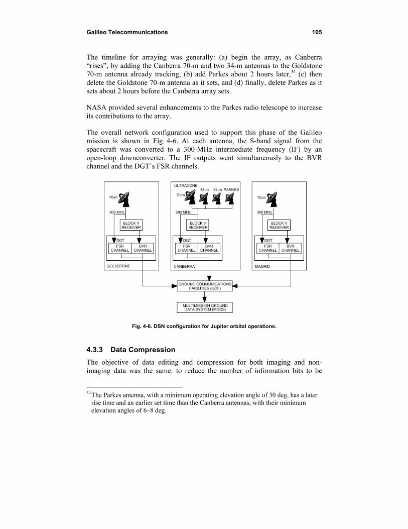
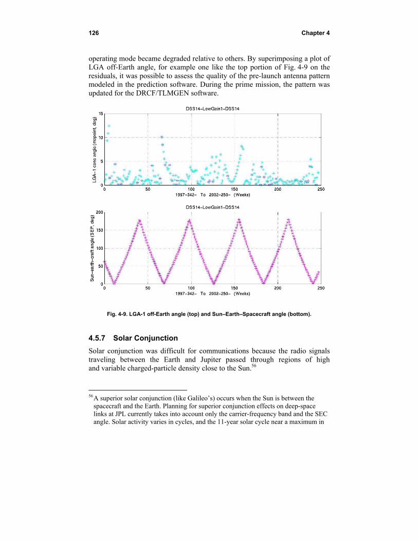