
CHAPTER 4 CONVEYANCE SYSTEM ANALYSIS & DESIGN · CHAPTER 4 CONVEYANCE SYSTEM ANALYSIS ... 4-13 4.5...
30
CHAPTER 4 CONVEYANCE SYSTEM ANALYSIS & DESIGN Contents 4.0 INTRODUTION 4-1 4.1 CONVEYANCE SYSTEM DESIGN FLOW 4-1 4.1.1 Rational Method 4-1 4.1.2 Santa Barbara Urban Hydrology Method 4-2 4.1.3 Western Washington Hydrology Model 4-2 4.2 ROUTE DESIGN AND EASEMENT REQUIREMENTS 4-2 4.2.1 Route Design 4-2 4.2.2 Discharge Type and Location 4-3 4.2.3 Easement and Setback Requirements 4-3 4.2.4 Datum 4-4 4.3 PIPES, OUTFALLS, AND PUMPS 4-5 4.3.1 Pipe Systems 4-5 4.3.2 Outfall Systems 4-11 4.3.3 Pump Systems 4-12 4.4 CULVERTS 4-13 4.5 OPEN CHANNELS 4-17 4.5.1 Natural Channels 4-17 4.5.2 Constructed Channels 4-17 4.6 DOWNSTREAM ANALYSIS 4-23 4.6.1 Level 11 Analysis 4-23 4.6.2 Level 2 Analysis 4-23 4.6.3 Level 3 Analysis 4-24 4.7 HYDRAULIC STRUCTURES 4-24 4.7.1 Flow Splitter Designs 4-24 4.7.2 Flow Spreading Options 4-26 i
Transcript of CHAPTER 4 CONVEYANCE SYSTEM ANALYSIS & DESIGN · CHAPTER 4 CONVEYANCE SYSTEM ANALYSIS ... 4-13 4.5...

CHAPTER 4 CONVEYANCE SYSTEM ANALYSIS & DESIGN
Contents
4.0 INTRODUTION 4-1 4.1 CONVEYANCE SYSTEM DESIGN FLOW 4-1 4.1.1 Rational Method 4-1 4.1.2 Santa Barbara Urban Hydrology Method 4-2 4.1.3 Western Washington Hydrology Model 4-2 4.2 ROUTE DESIGN AND EASEMENT REQUIREMENTS 4-2 4.2.1 Route Design 4-2 4.2.2 Discharge Type and Location 4-3
4.2.3 Easement and Setback Requirements 4-3 4.2.4 Datum 4-4
4.3 PIPES, OUTFALLS, AND PUMPS 4-5 4.3.1 Pipe Systems 4-5 4.3.2 Outfall Systems 4-11 4.3.3 Pump Systems 4-12 4.4 CULVERTS 4-13 4.5 OPEN CHANNELS 4-17 4.5.1 Natural Channels 4-17 4.5.2 Constructed Channels 4-17 4.6 DOWNSTREAM ANALYSIS 4-23 4.6.1 Level 11 Analysis 4-23 4.6.2 Level 2 Analysis 4-23 4.6.3 Level 3 Analysis 4-24 4.7 HYDRAULIC STRUCTURES 4-24 4.7.1 Flow Splitter Designs 4-24 4.7.2 Flow Spreading Options 4-26
i
CHAPTER 4 CONVEYANCE SYSTEM ANALYSIS & DESIGN
4.0 INTRODUCTION This chapter presents Kitsap County approved methods for the hydraulic analysis and design of conveyance systems. A conveyance system includes all portions of the surface water system, either natural or man-made, that transport surface and storm water runoff. This chapter contains the detailed design criteria, methods of analysis, and standard details for all components of the conveyance system. In some cases, reference is made to other adopted or accepted design standards and criteria such as the Washington State Department of Transportation/APWA (WSDOT/APWA) Standard Specifications for Road, Bridge, and Municipal Construction (most recent edition). 4.1 CONVEYANCE SYSTEM DESIGN FLOW
A. All conveyance systems must be designed, at a minimum, to convey a peak stormwater rate resulting from a 100-year frequency storm event, EXCEPT:
1. Other governing authorities may require that the design of some structures be
based on a larger storm event. 2. Some water quality facilities are designed to function primarily under low
flow conditions. However, unless higher flows are diverted from these water quality facilities per section 4.13, they must also be designed to have sufficient conveyance capacity for 100-year storm flow rates.
B. For all existing and proposed conveyance systems receiving drainage from a
contributing area of 25 acres or less and having a time of concentration of 100 minutes or less, the Rational Method may be used as described in this chapter. For all other conditions either the Santa Barbara Urban Hydrograph Model (SBUH) or the Western Washington Hydrology Model must be used.
4.1.1 RATIONAL METHOD
The traditional Rational Method, as described in most engineering manuals, is preferred by Kitsap County for designing systems serving smaller contributing basins primarily because it tends to provide higher runoff rates than hydrograph methods do, resulting in a more conservative design with a built-in factor of safety.
4-1

With the traditional Rational Method, peak runoff rates can be determined using the following formula:
Q = C I A
where Q = Runoff in cubic feet per second
C = Runoff coefficient I = Rainfall intensity in inches per hour A = Contributing area in acres
The runoff coefficient (C) should be based on Table 4.1, Runoff Coefficients - 'C' Values for the Rational Method. The rainfall intensity (I) should be based on Figure 4.1, Rainfall Intensity-Duration Curves, prepared by the U.S. Weather Bureau for the Mayfield - Bremerton - Kitsap County - Sumner areas. The traditional Rational Method, as described in most engineering manuals, is preferred by Kitsap County for designing systems serving smaller contributing basins primarily because it tends to provide higher runoff rates than hydrograph methods do, resulting in a more conservative design with a built-in factor of safety. 4.1.2 SANTA BARBARA URBAN HYDROGRAPH METHOD
Calculations shall be conducted in accordance with the instructions found in Volume III of the 2005 Department of Ecology’s Stormwater Management Manual for Western Washington (2005 DOE).
4.1.3 WESTERN WASHINGTON HYDROLOGY MODEL
See chapter 7 of this manual and Volume III of the 2005 DOE manual for a complete description of how to use the Western Washington Hydrology Model
4.2 ROUTE DESIGN AND EASEMENT REQUIREMENTS This section presents the general requirements for aligning conveyance systems and providing easements and setbacks to allow for proper maintenance and inspection of all conveyance system elements.
4.2.1 ROUTE DESIGN
The most efficient route selected for new conveyance systems will result from careful consideration of the topography of the area to be traversed, the legal property boundaries, and access for inspection and maintenance. The general requirements for route design are as follows:
4-2
1. Proposed new conveyance systems should be aligned to emulate the natural conveyance system to the extent feasible. Inflow to the system and discharge from the system should occur at the natural drainage points as determined by topography and existing drainage patterns.
2. New conveyance system alignments in residential subdivisions should be
located adjacent and parallel to property lines so that required drainage easements can be situated along property lines. Drainage easements should be located entirely on one property and not split between adjacent properties. Exception: Streams and natural drainage channels shall not be relocated to meet this requirement.
4.2.2 DISCHARGE TYPE AND LOCATION
Where no conveyance system exists at the abutting downstream property line and the natural (existing) discharge is unconcentrated, any runoff concentrated by the proposed project must be discharged as follows:
1. If the 100-year peak discharge is less than or equal to 0.2 cfs under existing
conditions and will remain less than or equal to 0.2 cfs under developed conditions, then the concentrated runoff may be discharged onto a rock pad or another system that serves to disperse flows.
2. If the 100-year peak discharge is less than or equal to 0.5 cfs under existing
conditions and will remain less than or equal to 0.5 cfs under developed conditions, then the concentrated runoff may be discharged through a dispersal trench or other dispersal system (see figure 4.17), provided the applicant can demonstrate that there will be no significant adverse impact to downhill properties or drainage systems.
3. If the 100-year peak discharge is greater than 0.5 cfs for either existing or developed
conditions, or if a significant adverse impact to downgradient properties or drainage systems is likely, then a conveyance system must be provided to convey the concentrated runoff across the downstream properties to an acceptable discharge point (i.e., an enclosed drainage system or open drainage feature where concentrated runoff can be discharged without significant adverse impact).
4.2.3 EASEMENT AND SETBACK REQUIREMENTS Proposed projects must comply with the following easement and setback requirements unless otherwise approved by the Director: 1. Any onsite conveyance system element constructed as part of a subdivision project
shall be located in a dedicated drainage easement, tract, or right-of-way that preserves the system's route and conveyance capacity and grants Kitsap County right of access for inspection, maintenance, and repair.
Exception: Roof downspout, minor yard, and footing drains do not require easements, tracts, or right-of-way. If easements are provided for these minor drains (or for other
4-3
utilities such as power, gas, or telephone), they need not comply with the requirements of this section.
Note: except for those facilities that have been formally accepted for maintenance by Kitsap County, maintenance and repair of drainage facilities on private property is the responsibility of the property owner.
2. Any onsite conveyance system element constructed under a commercial building or commercial development permit shall be covered by the drainage facility declaration of covenant and grant of easement that provides Kitsap County right of access for inspection, maintenance, and repair. Note: except for those facilities that have been formally accepted for maintenance by Kitsap County, maintenance and repair of drainage facilities on private property is the responsibility of the property owner.
3. Any offsite conveyance system element constructed through private property as part of a proposed project shall be located in a drainage easement.
4. All drainage easements, public and private, must have a minimum width of 15', with the exception that private secondary roof and yard drain systems may be located within 10' easements. All pipes must be located within the easement so that each pipe face or top edge of channel is no closer than 5' from its adjacent easement boundary (secondary roof and yard drain pipes shall be centered in the easement). Open channels shall be located within the easement so that the water surface elevation at the top of freeboard is no closer than 5' from each easement boundary. For pipes larger than 5' in diameter and for channels having a top width at freeboard wider than 5', the easement width must be accordingly larger than the minimum 15' in order to meet the required setbacks from the easement boundaries.
5. Maintenance access must be provided for all manholes, catch basins, vaults, or other drainage facilities that are to be maintained by Kitsap County. It is not generally necessary to provide vehicular access along the entire length of a drainage pipe or swale as long as access is provided at each end. Maintenance access shall consist of an access easement and a constructed access road, with turn-around if necessary. Access roads shall be constructed as specified in Chapter 7, Flow Control.
4.2.4 Datum A vertical datum shall be used in the design of all public drainage systems or systems that will be owned or operated by Kitsap County or that connect to a county system. All datum shall be either NGVD29 or NAVD88.
4-4

4.3 PIPES, OUTFALLS, AND PUMPS
This section presents the methods, criteria, and details for analysis and design of pipe systems, outfalls, and pump-dependent conveyance systems.
4.3.1 PIPE SYSTEMS
Pipe systems are networks of storm drain pipes, catch basins, manholes, inlets, and outfalls designed and constructed to convey surface water. The hydraulic analysis of flow in storm drain pipes typically is limited to gravity flow; however, in analyzing existing systems it may be necessary to address pressurized conditions. A properly designed pipe system will maximize hydraulic efficiency by utilizing proper material, slope, and pipe size. A. Design Criteria
1. General
All pipe material, joints, protective treatment, and construction workmanship shall be in accordance with WSDOT/APWA Standard Specifications, and AASHTO and ASTM treatment as noted below under "Allowable Pipe Materials." Note: The pipe materials and specifications included in this section are for conveyance systems installed according to engineering plans required for Kitsap County permits/approvals. Other pipe materials and specifications may be used by private property owners for drainage systems they construct and maintain when such systems are not required by or granted to Kitsap County.
2. Acceptable Pipe Sizes
The following pipe sizes shall be used for pipe systems to be maintained by Kitsap County: 8-inch (generally for use only in privately maintained systems or in special cases within road right-of-way1), 12-inch, 15-inch, 18-inch, 21-inch, 24-inch, and 30-inch. For pipes larger than 30-inch diameter, increasing increments of 6-inch intervals shall be used (36-inch, 42-inch, 48-inch, etc.).
3. Allowable Pipe Materials
The following pipe materials are allowed for use in meeting the requirements of this manual. Refer to WSDOT/APWA 7-02, 7-03 and 7-04 for detailed specifications for acceptable pipe materials. a. Plain and reinforced concrete pipe b. Corrugated or spiral rib aluminum pipe
v 1 Requires written approval from the County Road Engineer
4-5

c. Corrugated steel pipe, Aluminized or Galvanized2 with treatments 1 through 6
d. Spiral rib steel pipe, Aluminized or Galvanized with treatments 1 through 6
e. Ductile iron (water supply, Class 50 or 52) f. Lined corrugated polyethylene pipe (LCPE)3 g. Corrugated polyethylene pipe (CPE)4 that is single wall and fully
corrugated h. Polyvinyl chloride (PVC)5 pipe 1. Solid wall polyethylene pipe (SWPE; also known as HDPE pipe or HDPP)6
4. Allowable Pipe Joints
a. Concrete pipe shall be rubber gasketed. b. CMP shall be rubber gasketed and securely banded. c. Spiral rib pipe shall be "hat-banded" with neoprene gaskets. d. Ductile pipe joints shall be flanged, bell and spigot, or restrained
mechanical joints. e. LCPE pipe joints shall conform to the current WSDOT/APWA Standard
Specifications. f. CPE single wall, fully corrugated pipe joints shall conform to the current
WSDOT/APWA Standard Specifications. g. PVC pipe shall be installed following procedures outlined in ASTM
D2321; joints shall conform to ASTM D3212, and gaskets shall conform to ASTM F477.
h. SWPE pipe shall be jointed by butt fusion methods or flanged.
vi 2 Galvanized metals leach zinc into the environment, especially in standing water situations. High zinc concentrations,
sometimes in the range that can be toxic to aquatic life, have been observed in the region. Therefore, use of galvanized materials should be avoided. Where other metals, such as aluminum or stainless steel, or plastics are available, they shall be used. If these materials are not available, asphalt coated galvanized materials may then be used.
3 LCPE pipe and fittings shall be manufactured from high density polyethylene resin which shall meet or exceed the requirements of Type 111, Category 3, 4 or 5, Grade P23, P33 or P34, Class C per ASTM D1248. In addition, the pipe shall comply with all material and stiffness requirements of AASHTO M294.
4 CPE pipe (single wall, fully corrugated) is allowed only for use in private storm sewer systems such as downspout, footing, or yard drain collectors on private property.
5 PVC pipe is allowed only for use in privately maintained drainage systems. PVC pipe must be SDR 35 or thicker and meet the requirements of ASTM D3034.
6 SWPE pipe is normally used outside of Kitsap County right-of-way, such as on steep slope installations. Connections to Kitsap County road drainage systems are allowed for pipe diameters of 12" or greater. SWPE pipe shall comply with the requirements of Type III C5P34 as tabulated in ASTM D1248, shall have the PPI recommended designation of PE3408, and shall have an ASTM D3350 cell classification of 345534C. The pipe shall have a manufacturer's recommended hydrostatic design stress rating of 800 psi based on a material with a 1600 psi design basis determined in accordance with ASTM D2837-69. The pipe shall have a suggested design working pressure of 50 psi at 73.4o F and SDR of 32.5.
4-6

5. Pipe Alignment
a. Pipes must be laid true to line and grade with no curves, bends, or deflections in any direction. Exception: Vertical deflections in SWPE and ductile iron pipe with flanged restrained mechanical joint bends (not greater than 30
o) on steep slopes, provided the pipe drains.
b. A break in grade or alignment, or changes in pipe material shall occur only at catch basins or manholes.
6. Changes in Pipe Size
a. Increase or decreases in pipe size are allowed only at junctions and
structures. b. When connecting pipes at structures, match any of the following (in
descending order of preference): crowns, 80% diameters,7 or inverts of pipes. Side lateral connections8, 12 inches and smaller, are exempt from this requirement.
c. Drop manholes may be used for energy dissipation when pipe velocities exceed 10 feet per second. External drop manholes are preferred where maintenance access to the upstream pipe is preserved by use of a tee section. Internal drop structures may be approved only if adequate scour protection is provided for the manhole walls. Drop structures must be individually engineered to account for design variations, such as flow rates, velocities, scour potential, and tipping forces. Downsizing pipes larger than 12 inches may be allowed provided pipe capacity is adequate for design flows.
Note: The above criteria do not apply to detention tanks.
7. Structures Table 4.3 lists typical drainage structures with corresponding maximum allowable pipe sizes.
a. Catch basin (or manhole) diameter shall be determined by pipe orientation at the junction structure. A plan view of the junction structure, drawn to scale, will be required when more than four pipes enter the structure on the same plane, or if angles of approach and clearance between pipes is of concern. The plan view (and sections if necessary) must ensure a minimum distance (of solid concrete wall) between pipe openings of 8 inches for 48-inch and 54-inch catch basins, and 12 inches for 72-inch and 96-inch catch basins.
vii 7 Match point is at 80% of the pipe diameter, measured from the invert of the respective pipes. 8 Side laterals include any 8-inch or smaller pipe connected to the main conveyance system at a catch basin, or
manhole, as allowed under this manual. In addition, 12-inch and smaller pipes that serve a single inlet point (e.g., roadway simple inlets, footing drains, and lot stubouts including manifold systems serving multiple residential lots) are also included. Excluded from this definition are inlet pipes which contribute 30% or more of the total flow into a catch basin, or which collect or convey flows from a continuous source.
4-7

b. Evaluation of the structural integrity for H-20 loading, or as required by the Kitsap County Road Standards, may be required for multiple junction catch basins and other structures.
c. Catch basins shall be provided within 50 feet of the entrance to a pipe system to provide for silt and debris removal.
d. All SWPE pipe systems (including buried SWPE pipe) must be secured at the upstream end. Where connecting to a structure, the downstream end shall be placed in a 4-foot section of the next larger pipe size. This sliding sleeve connection allows for the high thermal expansion/contraction coefficient of this pipe material.
e. The maximum slope of the ground surface for a radius of 5 feet around a catch basin grate or solid lid should be 5:1 to facilitate maintenance access. Where not physically feasible, a maximum slope of 3:1 (H:V) shall be provided around at least 50% of the catch basin circumference.
8. Pipe Cover
a. Pipe cover, measured from the finished grade elevation to the top of the
outside surface of the pipe, shall be 2 feet minimum unless otherwise specified or allowed below. Under drainage easements, driveways, parking stalls, or other areas subject to light vehicular loading, pipe cover may be reduced to 1 foot minimum if the design considers expected vehicular loading and the cover is consistent with pipe manufacturer's recommendations. Pipe cover in areas not subject to vehicular loads, such as landscape planters and yards, may be reduced to 1-foot minimum.
b. Pipe cover over concrete pipe shall comply with Table 4.4. For other pipe types, the manufacturer's specifications or other documentation shall be provided for proposed cover in excess of 30 feet. Caution: Additional precautions to protect against crushing during construction may be needed under roadways if the road bed is included to meet minimum cover requirements. Damaged pipe shall be replaced.
c. For proposed pipe arches, the manufacturer's specifications or other documentation shall be provided for proposed cover in excess of 8 feet.
9. Pipe Clearances
a. A minimum of 6 inches vertical and 3 feet horizontal clearance (outside surfaces) shall be provided between storm drain pipes and other utility pipes and conduits. When crossing sanitary sewer lines, the Washington Department of Ecology criteria shall apply.
10. Pipe Compaction and Backfill
a. Pipe compaction and backfill shall be in accordance with Figure 4.2.
11. Pipe System Connections
a. Connections to a pipe system shall be made only at catch basins or
manholes. No wyes or tees are allowed except on roof/footing/yard drain systems on pipes 8 inches in diameter or less, with clean-outs upstream of
4-8
each wye or tee. Additional exceptions may be made for steep slope applications of SWPE pipe, as deemed prudent by geotechnical review.
12. Pipe Anchors
a. Table 4.2 presents the requirements, by pipe material, for anchoring pipe
systems,and Figure 4.4 show typical details of pipe anchors.
13. Debris Barriers
a. Debris barriers (trash racks) are required on all pipes 18 to 36 inches in diameter entering a closed pipe system. Debris barriers shall have a bar spacing of 6 inches. See Figure 4.5 for required debris barriers on pipe ends outside of roadways. See Figure 4.6 and Section 4.4 for requirements on pipe ends (culverts) projecting from driveway or roadway side slopes.
14. Outfalls
a. Outfalls shall be designed as detailed in Section 4.3.2.
15. Other Details
a. In addition to the details shown in Figure 4.1 through Figure 4.6, Standard
Construction Details are available in the APWA/WSDOT Standard Plans for Road, Bridge and Municipal Construction.
16. Methods of Analysis
This section presents the methods of analysis for designing new or evaluating existing pipe systems for compliance with the conveyance capacity requirements.
DESIGN FLOWS Design flows for sizing or assessing the capacity of pipe systems shall be determined using the hydrologic analysis methods described in section 4.1.
INLET GRATE CAPACITY The methods described in Chapter 5, Sections 4 and 5, of the Washington State Department of Transportation (WSDOT) Hydraulics Manual may be used in determining the capacity of inlet grates when capacity is of concern, with the following exceptions: b. Use 100-year design flows as computed per section 4.1. c. Assume grate areas on slopes are 80% free of debris; "vaned" grates,
95% free. d. Assume grate areas in sags or low spots are 50% free of debris;
"vaned" grates, 75% free.
4-9
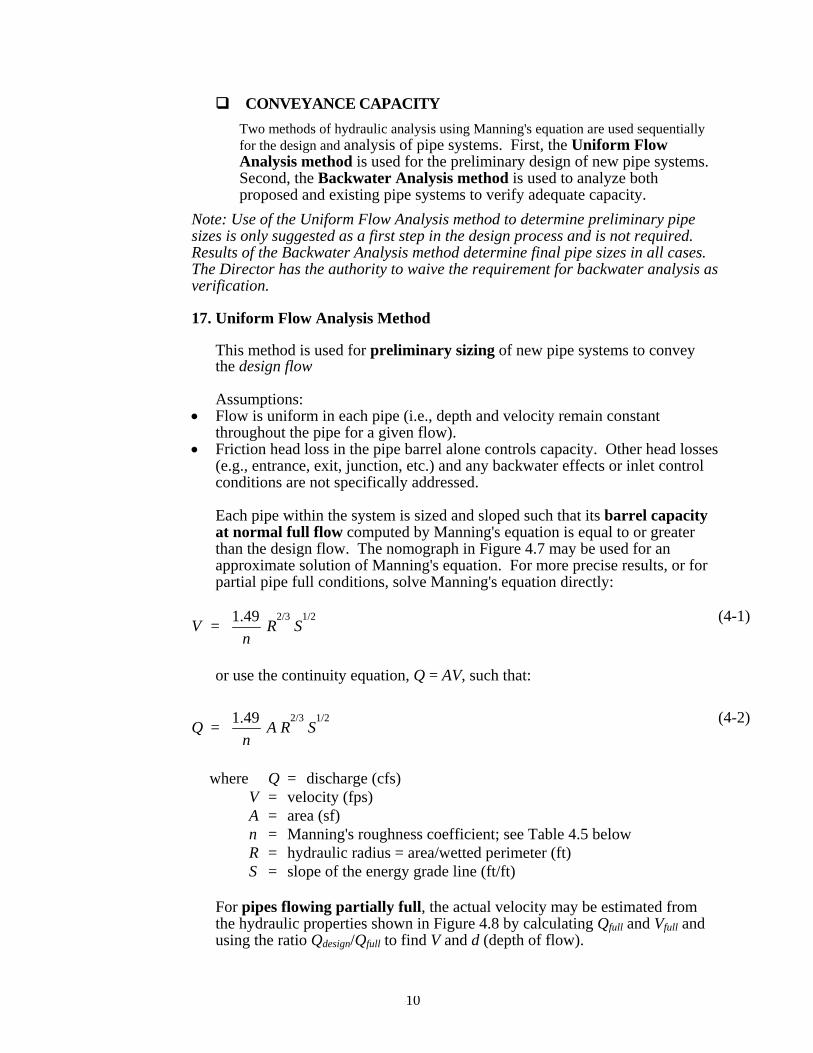
CONVEYANCE CAPACITY Two methods of hydraulic analysis using Manning's equation are used sequentially for the design and analysis of pipe systems. First, the Uniform Flow Analysis method is used for the preliminary design of new pipe systems. Second, the Backwater Analysis method is used to analyze both proposed and existing pipe systems to verify adequate capacity.
Note: Use of the Uniform Flow Analysis method to determine preliminary pipe sizes is only suggested as a first step in the design process and is not required. Results of the Backwater Analysis method determine final pipe sizes in all cases. The Director has the authority to waive the requirement for backwater analysis as verification.
17. Uniform Flow Analysis Method
This method is used for preliminary sizing of new pipe systems to convey the design flow Assumptions:
• Flow is uniform in each pipe (i.e., depth and velocity remain constant throughout the pipe for a given flow).
• Friction head loss in the pipe barrel alone controls capacity. Other head losses (e.g., entrance, exit, junction, etc.) and any backwater effects or inlet control conditions are not specifically addressed.
Each pipe within the system is sized and sloped such that its barrel capacity at normal full flow computed by Manning's equation is equal to or greater than the design flow. The nomograph in Figure 4.7 may be used for an approximate solution of Manning's equation. For more precise results, or for partial pipe full conditions, solve Manning's equation directly:
V = n49.1 R
2/3 S
1/2 (4-1)
or use the continuity equation, Q = AV, such that:
Q = n49.1 A R
2/3 S
1/2 (4-2)
where Q = discharge (cfs) V = velocity (fps) A = area (sf) n = Manning's roughness coefficient; see Table 4.5 below R = hydraulic radius = area/wetted perimeter (ft) S = slope of the energy grade line (ft/ft)
For pipes flowing partially full, the actual velocity may be estimated from the hydraulic properties shown in Figure 4.8 by calculating Qfull and Vfull and using the ratio Qdesign/Qfull to find V and d (depth of flow).
4-10

Table 4.5 provides the recommended Manning's "n" values for preliminary design using the Uniform Flow Analysis method for pipe systems. Note: The "n" values for this method are 15% higher in order to account for entrance, exit, junction, and bend head losses.
18. Backwater Analysis Method This method is used to analyze the capacity of both new and existing pipe systems to convey the required design flow. In either case, pipe system structures must be demonstrated to contain the headwater surface (hydraulic grade line) for the specified peak flow rate. This method is used to compute a simple backwater profile (hydraulic grade line) through a proposed or existing pipe system for the purposes of verifying adequate capacity. It incorporates a re-arranged form of Manning's equation expressed in terms of friction slope (slope of the energy grade line in ft/ft). The friction slope is used to determine the head loss in each pipe segment due to barrel friction, which can then be combined with other head losses to obtain water surface elevations at all structures along the pipe system. The backwater analysis begins at the downstream end of the pipe system and is computed back through each pipe segment and structure upstream. The friction, entrance, and exit head losses computed for each pipe segment are added to that segment's tailwater elevation (the water surface elevation at the pipe's outlet) to obtain its outlet control headwater elevation. This elevation is then compared with the inlet control headwater elevation, computed assuming the pipe's inlet alone is controlling capacity using the methods for inlet control presented in Section 4.4. The condition that creates the highest headwater elevation determines the pipe's capacity. The approach velocity head is then subtracted from the controlling headwater elevation, and the junction and bend head losses are added to compute the total headwater elevation, which is then used as the tailwater elevation for the upstream pipe segment. The Backwater Calculation Sheet in Figure 4.9 may be used to compile the head losses and headwater elevations for each pipe segment. The numbered columns on this sheet are described in Figure 4.10. An example calculation is performed in Figure 4.11.
Note: This method should not be used to compute stage/discharge curves for level pool routing purposes. Instead, a more sophisticated backwater analysis using a computer software program is recommended for that purpose.
4.3.2 OUTFALL SYSTEMS
Properly designed outfalls are critical to ensuring no adverse impacts occur as the result of concentrated discharges from pipe systems and culverts, both onsite and downstream. Outfall systems include rock splash pads, flow dispersal trenches, gabion or other energy dissipaters, and tightline systems. A tightline system is typically a continuous length of pipe used to convey flows down a steep or sensitive slope with appropriate energy dissipation at the discharge end. In
4-11

general, it is recommended that conveyance systems be designed to reduce velocity above outfalls to the extent feasible.
A. Design Criteria
1. General At a minimum, all outfalls shall be provided with a rock splash pad except as specified below and in Table 4.6: a. The flow dispersal trench shown in Figure 4.16 shall only be used as an
outfall. b. For outfalls with a velocity at design flow greater than 10 fps, a gabion
dissipater or engineered energy dissipater shall be required. Note the gabion outfall detail shown in Figure 4.18 is illustrative only; a design engineered to specific site conditions is required. Gabions shall conform to WDSOT/APWA specifications.
c. Engineered energy dissipaters, including stilling basins, drop pools, hydraulic jump basins, baffled aprons, and bucket aprons, are required for outfalls with velocity at design flow greater than 20 fps. These should be designed using published or commonly known techniques found in such references as Hydraulic Design of Energy Dissipaters for Culverts and Channels, published by the Federal Highway Administration of the United States Department of Transportation; Open Channel Flow, by V.T. Chow; Hydraulic Design of Stilling Basins and Energy Dissipaters, EM 25, Bureau of Reclamation (1978); and other publications, such as those prepared by the Soil Conservation Service (now Natural Resource Conservation Service). Alternate mechanisms, such as bubble-up structures (which will eventually drain) and structures fitted with reinforced concrete posts, require an individual approval and must be designed using sound hydraulic principles and considering constructability and ease of maintenance.
2. Tightline Systems
a. Outfall tightlines may be installed in trenches with standard bedding on
slopes up to 40%. In order to minimize disturbance to slopes greater than 40%, it is recommended that tightlines be placed at grade with proper pipe anchorage and support. At-grade tightlines must be SWPE.
b. SWPE tightlines must be designed to address the material limitations, particularly thermal expansion and contraction and pressure design, as specified by the manufacturer. The coefficient of thermal expansion and contraction for SWPE is on the order of 0.001 inch per foot per Fahrenheit degree. Sliding sleeve connections shall be used to address this thermal expansion and contraction. These sleeve connections consist of a section of the appropriate length of the next larger size diameter of pipe into
4-12

which the outfall pipe is fitted. These sleeve connections must be located as close to the discharge end of the outfall system as is practical.
c. SWPE tightlines shall be designed and sized using the applicable design criteria and methods of analysis specified for pipe systems in Section 4.3.1.
Due to the ability of SWPE tightlines to transmit flows of very high energy, special consideration for energy dissipation must be made. Details of a sample "gabion mattress energy dissipater" have been provided as Figure 4.18. Details of a sample "tee type dissipater" have been provided as Figure 4.14 Caution: the in-stream sample gabion mattress energy dissipater may not be acceptable within the ordinary high water mark of fish-bearing waters or where gabions will be subject to abrasion from upstream channel sediments. A four-sided gabion basket located outside the ordinary high water mark should be considered for these applications.
4.3.3 PUMP SYSTEMS
Pump systems may be used for conveyance of flows internal to a site if located on private property and privately maintained.
A. Design Criteria Proposed pump systems must meet the following minimum requirements:
1. The pump system must be privately owned and maintained. 2. The pump system shall be used to convey water from one location or elevation to
another within the site. 3. The pump system must have a dual pump (alternating) equipped with an external
alarm system. 4. The pump system shall not be used to circumvent any other Kitsap County
drainage requirements, and construction and operation of the pump system shall not violate any other Kitsap County requirements.
5. The gravity-flow components of the drainage system to and from the pump system must be designed so that pump failure does not result in flooding of a building or emergency access, or overflow to a location other than the natural discharge point for the site.
B. Methods of Analysis
Pump systems must be sized to convey the anticipated on site flows up to the 100 yr recurrence interval.
4.4 CULVERTS
4-13

This section presents the methods, criteria, and details for hydraulic analysis and design of culverts. Culverts are relatively short segments of pipe of circular, elliptical, rectangular, or arch cross section. They are usually placed under road embankments or driveways to convey surface water flow safely under the embankment. They may be used to convey flow from constructed or natural channels including streams.
A. Design Criteria
1. General
a. All circular pipe culverts shall conform to any applicable design criteria specified for pipe systems in Section 4.3.1.
b. All other types of culverts shall conform to manufacturer's specifications. c. Minimum culvert diameters are as follows:
(1) For cross culverts under public and private roadways - min. 18". (2) For all other roadway culverts, including driveway culverts - min. 12". (3) No bends shall be permitted in culvert pipes.
d. Minimum cover over culverts: 2' under primary roads, 1' under secondary
roads and in all roadside applications and on private property. e. Maximum culvert length: 300'.
2. Headwater
a. For culverts 18-inch diameter or less, the maximum allowable headwater
elevation (measured from the inlet invert) shall not exceed 2 times the pipe diameter or arch-culvert-rise at design flow
b. For culverts larger than 18-inch diameter, the maximum allowable design flow headwater elevation (measured from the inlet invert) shall not exceed 1.5 times the pipe diameter or arch-culvert-rise at design flow.
c. The maximum headwater elevation at design flow shall be below any road or parking lot subgrade.
3. Inlets and Outlets
a. All inlets and outlets in or near roadway embankments must be flush with and conforming to the slope of the embankment.
b. For culverts 18-inch diameter and larger, the embankment around the culvert inlet shall be protected from erosion by rock lining or riprap as specified in Table 4.6, except the length shall extend at least 5 feet upstream of the culvert, and the height shall be at or above the design headwater elevation.
c. Inlet structures, such as concrete headwalls, may provide a more economical design by allowing the use of smaller entrance coefficients and, hence, smaller diameter culverts. When properly designed, they will also protect the embankment from erosion and eliminate the need for rock lining.
4-14

d. In order to maintain the stability of roadway embankments, concrete headwalls, wingwalls, or tapered inlets and outlets may be required if right-of-way or easement constraints prohibit the culvert from extending to the toe of the embankment slopes. All inlet structures or headwalls installed in or near roadway embankments must be flush with and conforming to the slope of the embankment.
e. Debris barriers (trash racks) are required on the inlets of all culverts that are over 60 feet in length and are 18 to 36 inches in diameter. Debris barriers shall have a bar spacing of 6 inches. This requirement also applies to the inlets of pipe systems. See Figure 4.5 and Figure 4.6 for debris barrier details.
f. For culverts 18-inch diameter and larger, the receiving channel of the outlet shall be protected from erosion by rock lining specified in Table 4.6, except the height shall be one foot above maximum tailwater elevation or one foot above the crown, whichever is higher.
3. Methods of Analysis This section presents the methods of analysis for designing new or evaluating existing culverts for compliance with the conveyance capacity
DESIGN FLOWS Design flows for sizing or assessing the capacity of culverts shall be determined using the hydrologic analysis methods described in section 4.1.
CONVEYANCE CAPACITY The theoretical analysis of culvert capacity can be extremely complex because of the wide range of possible flow conditions that can occur due to various combinations of inlet and outlet submergence and flow regime within the culvert barrel. An exact analysis usually involves detailed backwater calculations, energy and momentum balance, and application of the results of hydraulic model studies. However, simple procedures have been developed where the various flow conditions are classified and analyzed on the basis of a control section. A control section is a location where there is a unique relationship between the flow rate and the upstream water surface elevation. Many different flow conditions exist over time, but at any given time the flow is either governed by the culvert's inlet geometry (inlet control) or by a combination of inlet geometry, barrel characteristics, and tailwater elevation (outlet control). Figure 4.19 illustrates typical conditions of inlet and outlet control. The procedures presented in this section provide for the analysis of both inlet and outlet control conditions to determine which governs.
A. Inlet Control Analysis Nomographs such as those provided in Figure 4.20 and Figure 4.21 may be used to determine the inlet control headwater depth at design flow for various types of culverts and inlet configurations. These nomographs
4-15
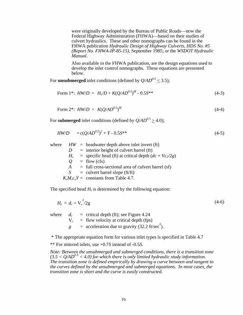
were originally developed by the Bureau of Public Roads—now the Federal Highway Administration (FHWA)—based on their studies of culvert hydraulics. These and other nomographs can be found in the FHWA publication Hydraulic Design of Highway Culverts, HDS No. #5 (Report No. FHWA-IP-85-15), September 1985; or the WSDOT Hydraulic Manual. Also available in the FHWA publication, are the design equations used to develop the inlet control nomographs. These equations are presented below.
For unsubmerged inlet conditions (defined by Q/AD0.5 < 3.5);
Form 1*: HW/D = Hc/D + K(Q/AD0.5)M - 0.5S** (4-3)
Form 2*: HW/D = K(Q/AD0.5)M (4-4)
For submerged inlet conditions (defined by Q/AD0.5 > 4.0);
HW/D = c(Q/AD0.5)2 + Y - 0.5S** (4-5)
where HW = headwater depth above inlet invert (ft) D = interior height of culvert barrel (ft) Hc = specific head (ft) at critical depth (dc + Vc2/2g) Q = flow (cfs) A = full cross-sectional area of culvert barrel (sf) S = culvert barrel slope (ft/ft) K,M,c,Y = constants from Table 4.7. The specified head Hc is determined by the following equation:
Hc = dc + Vc2/2g (4-6)
where dc = critical depth (ft); see Figure 4.24 Vc = flow velocity at critical depth (fps) g = acceleration due to gravity (32.2 ft/sec2). * The appropriate equation form for various inlet types is specified in Table 4.7 ** For mitered inlets, use +0.7S instead of -0.5S. Note: Between the unsubmerged and submerged conditions, there is a transition zone (3.5 < Q/AD0.5 < 4.0) for which there is only limited hydraulic study information. The transition zone is defined empirically by drawing a curve between and tangent to the curves defined by the unsubmerged and submerged equations. In most cases, the transition zone is short and the curve is easily constructed.
4-16

B. Outlet Control Analysis Nomographs such as those provided in Figure 4.22 and Figure 4.23 may be used to determine the outlet control headwater depth at design flow for various types of culverts and inlets. Outlet control nomographs other than those provided can be found in FHWA HDS No.5 or the WSDOT Hydraulic Manual. The outlet control headwater depth may also be determined using the simple Backwater Analysis method presented in Section 4.3.1 for analyzing pipe system capacity. This procedure is summarized as follows for culverts:
HW = H + TW - LS (4-7)
where H = Hf + He + Hex
Hf = friction loss (ft) = (V2n2L)/(2.22R1.33) Note: If (Hf+TW-LS) < D, adjust Hf such that (Hf+TW-LS) = D. This
will keep the analysis simple and still yield reasonable results (erring on the conservative side).
He = entrance head loss (ft) = Ke(V2/2g)
Hex = exit head loss (ft) = V2/2g TW = tailwater depth above invert of culvert outlet (ft) Note: If TW < (D+dc)/2, set TW = (D+dc)/2. This will keep the
analysis simple and still yield reasonable results. L = length of culvert (ft) S = slope of culvert barrel (ft/ft) D = interior height of culvert barrel (ft) V = barrel velocity (fps) n = Manning's roughness coefficient from Table 4. R = hydraulic radius (ft) Ke = entrance loss coefficient (from Table 4.8) g = acceleration due to gravity (32.2 ft/sec2) dc = critical depth (ft); see Figure 4.24
Note: The above procedure should not be used to develop stage/discharge curves for level pool routing purposes because its results are not precise for flow conditions where the hydraulic grade line falls significantly below the culvert crown (i.e., less than full flow conditions).
4.5 OPEN CHANNELS
Open channels may be classified as either natural or constructed. Natural channels are generally referred to as rivers, streams, creeks, or swales, while constructed channels are most often called ditches, or simply channels. The Critical Areas Ordinance codified as title 19 of the Kitsap County Code should be reviewed for requirements related to streams.
4-17

4.5.1 Natural Channels Natural channels are defined as those that have occurred naturally due to the flow of surface waters, or those that, although originally constructed by human activity, have taken on the appearance of a natural channel including a stable route and biological community. They may vary hydraulically along each channel reach and should be left in their natural condition, wherever feasible or required, in order to maintain natural hydrologic functions and wildlife habitat benefits from established vegetation.
4.5.2 Constructed Channels Constructed channels are those constructed or maintained by human activity and include bank stabilization of natural channels. Constructed channels shall be either vegetation-lined, rock-lined, or lined with appropriately bioengineered vegetation. • Vegetation-lined channels are the most desirable of the constructed channels when
properly designed and constructed. The vegetation stabilizes the slopes of the channel, controls erosion of the channel surface, and removes pollutants. The channel storage, low velocities, water quality benefits, and greenbelt multiple-use benefits create significant advantages over other constructed channels. The presence of vegetation in channels creates turbulence that results in loss of energy and increased flow retardation; therefore, the design engineer must consider sediment deposition and scour, as well as flow capacity, when designing the channel.
• Rock-lined channels are necessary where a vegetative lining will not provide adequate protection from erosive velocities. They may be constructed with riprap, gabions, or slope mattress linings. The rock lining increases the turbulence, resulting in a loss of energy and increased flow retardation. Rock lining also permits a higher design velocity and therefore a steeper design slope than in grass-lined channels. Rock linings are also used for erosion control at culvert and storm drain outlets, sharp channel bends, channel confluences, and locally steepened channel sections.
• Bioengineered vegetation lining is a desirable alternative to the conventional methods of rock armoring. Soil bioengineering is a highly specialized science that uses living plants and plant parts to stabilize eroded or damaged land. Properly bioengineered systems are capable of providing a measure of immediate soil protection and mechanical reinforcement. As the plants grow they produce a vegetative protective cover and a root reinforcing matrix in the soil mantle. This root reinforcement serves several purposes: a. The developed anchor roots provide both shear and tensile strength to the soil,
thereby providing protection from the frictional shear and tensile velocity components to the soil mantle during the time when flows are receding and pore pressure is high in the saturated bank.
b. The root mat provides a living filter in the soil mantle that allows for the natural release of water after the high flows have receded.
c. The combined root system exhibits active friction transfer along the length of the living roots. This consolidates soil particles in the bank and serves to protect the soil structure from collapsing and the stabilization measures from failing. The vegetative cover of bioengineered systems provides immediate protection during high flows by laying flat against the bank and covering the soil like a blanket. It also reduces pore pressure in saturated banks through transpiration by
4-18

acting as a natural "pump" to "pull" the water out of the banks after flows have receded.
A. DESIGN CRITERIA
1. General
a. Open channels shall be designed to provide required conveyance capacity and bank stability while allowing for aesthetics, habitat preservation, and enhancement.
b. An access easement for maintenance is required along all constructed channels located on private property. Required easement widths are listed in section 4.2.3
c. Channel cross-section geometry shall be trapezoidal, triangular, parabolic, or segmental as shown in Figure 4.27 through Figure 4.29. Side slopes shall be no steeper than 3:1 for vegetation-lined channels and 2:1 for rock-lined channels.
d. Vegetation-lined channels shall have bottom slope gradients of 6% or less and a maximum velocity at design flow of 5 fps (see Table 4.9).
e. Rock-lined channels or bank stabilization of natural channels shall be used when design flow velocities exceed 5 feet per second. Rock stabilization shall be in accordance with Table 4.9 or stabilized with bioengineering methods as described above in "Constructed Channels.”
f. Open Channels shall be designed to provide sufficient freeboard so as to not saturate any adjacent public road base when conveying the design flow. A minimum of 1 foot of freeboard is recommended, but in no case shall channel freeboard be less than 0.5 feet.
• Riprap Design9 When riprap is set, stones are placed on the channel sides and bottom to protect the underlying material from being eroded. Proper riprap design requires the determination of the median size of stone, the thickness of the riprap layer, the gradation of stone sizes, and the selection of angular stones that will interlock when placed. Research by the U.S. Army Corps of Engineers has provided criteria for selecting the median stone weight, W50 (Figure 4.25). If the riprap is to be used in a highly turbulent zone (such as at a culvert outfall, downstream of a stilling basin, at sharp changes in channel geometry, etc.), the median stone W50 should be increased from 200% to 600% depending on the severity of the locally high turbulence. The thickness of the riprap layer should generally be twice the median stone diameter (D50) or at least that of the maximum stone. The riprap should have a reasonably well graded assortment of stone sizes within the following gradation: 1.25 ≤ Dmax/D50 ≤ 1.50 D15/D50 = 0.50
xix 9 From a paper prepared by M. Schaefer, Dam Safety Section, Washington State Department of Ecology.
4-19

Dmin/D50 = 0.25 Detailed design methodology may be found in the Corps publication EM 1110-02-1601, Engineering and Design – Hydraulic Design of Flood Control Channels. For a more detailed analysis and design procedure for riprap requiring water surface profiles and estimates of tractive force, refer to the paper by Maynord et al in Journal of Hydraulic Engineering (A.S.C.E.), July 1989.
• Riprap Filter Design Riprap should be underlain by a sand and gravel filter (or filter fabric) to keep the fine materials in the underlying channel bed from being washed through the voids in the riprap. Likewise, the filter material must be selected so that it is not washed through the voids in the riprap. Adequate filters can usually be provided by a reasonably well graded sand and gravel material where: D15 < 5d85
The variable d85 refers to the sieve opening through which 85% of the material being protected will pass, and D15 has the same interpretation for the filter material. A filter material with a D50 of 0.5 mm will protect any finer material including clay. Where very large riprap is used, it is sometimes necessary to use two filter layers between the material being protected and the riprap.
Example: What embedded riprap design should be used to protect a streambank at a level culvert outfall where the outfall velocities in the vicinity of the downstream toe are expected to be about 8 fps? From Figure 4.25, W50 = 6.5 lbs, but since the downstream area below the outfall will be subjected to severe turbulence, increase W50 by 400% so that: W50 = 26 lbs, D50 = 8.0 inches The gradation of the riprap is shown in Figure 4.26, and the minimum thickness would be 1 foot (from Table 4.9); however, 16 inches to 24 inches of riprap thickness would provide some additional insurance that the riprap will function properly in this highly turbulent area. Figure 4.26 shows that the gradation curve for ASTM C33, size number 57 coarse aggregate (used in concrete mixes), would meet the filter criteria. Applying the filter criteria to the coarse aggregate demonstrates that any underlying material whose gradation was coarser than that of a concrete sand would be protected.
2. Methods of Analysis This section presents the methods of analysis for designing new or evaluating existing open channels for compliance with the conveyance capacity requirements.
DESIGN FLOWS Design flows for sizing and assessing the capacity of open channels shall be determined using the hydrologic analysis methods described in Chapter 4.1
4-20
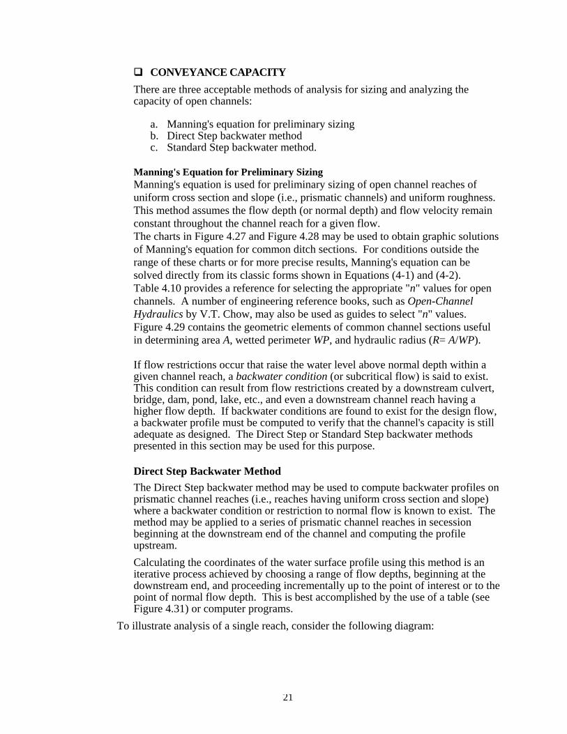
CONVEYANCE CAPACITY There are three acceptable methods of analysis for sizing and analyzing the capacity of open channels:
a. Manning's equation for preliminary sizing b. Direct Step backwater method c. Standard Step backwater method.
Manning's Equation for Preliminary Sizing Manning's equation is used for preliminary sizing of open channel reaches of uniform cross section and slope (i.e., prismatic channels) and uniform roughness. This method assumes the flow depth (or normal depth) and flow velocity remain constant throughout the channel reach for a given flow. The charts in Figure 4.27 and Figure 4.28 may be used to obtain graphic solutions of Manning's equation for common ditch sections. For conditions outside the range of these charts or for more precise results, Manning's equation can be solved directly from its classic forms shown in Equations (4-1) and (4-2). Table 4.10 provides a reference for selecting the appropriate "n" values for open channels. A number of engineering reference books, such as Open-Channel Hydraulics by V.T. Chow, may also be used as guides to select "n" values. Figure 4.29 contains the geometric elements of common channel sections useful in determining area A, wetted perimeter WP, and hydraulic radius (R= A/WP). If flow restrictions occur that raise the water level above normal depth within a given channel reach, a backwater condition (or subcritical flow) is said to exist. This condition can result from flow restrictions created by a downstream culvert, bridge, dam, pond, lake, etc., and even a downstream channel reach having a higher flow depth. If backwater conditions are found to exist for the design flow, a backwater profile must be computed to verify that the channel's capacity is still adequate as designed. The Direct Step or Standard Step backwater methods presented in this section may be used for this purpose.
Direct Step Backwater Method The Direct Step backwater method may be used to compute backwater profiles on prismatic channel reaches (i.e., reaches having uniform cross section and slope) where a backwater condition or restriction to normal flow is known to exist. The method may be applied to a series of prismatic channel reaches in secession beginning at the downstream end of the channel and computing the profile upstream. Calculating the coordinates of the water surface profile using this method is an iterative process achieved by choosing a range of flow depths, beginning at the downstream end, and proceeding incrementally up to the point of interest or to the point of normal flow depth. This is best accomplished by the use of a table (see Figure 4.31) or computer programs.
To illustrate analysis of a single reach, consider the following diagram:
4-21

���������������������������������������������������������������������������������������������������������
Equating the total head at cross sections 1 and 2, the following equation may be written:
SoΔx + y1 + g
V2
21
1α = y2 + g
V2
22
2α + Sf Δx (4-8)
where, Δx = distance between cross sections (ft) y1, y2 = depth of flow (ft) at cross sections 1 and 2 V1, V2 = velocity (fps) at cross sections 1 and 2 α1, α2 = energy coefficient at cross sections 1 and 2 So = bottom slope (ft/ft) Sf = friction slope = (n2V2)/(2.21R1.33) g = acceleration due to gravity, (32.2 ft/sec2) If the specific energy E at any one cross section is defined as follows:
E = y + g
V2
2
α (4-9)
and assuming α = α1 = α2 where α is the energy coefficient that corrects for the non-uniform distribution of velocity over the channel cross section, Equations 4-8 and 4-9 can be combined and rearranged to solve for Δx as follows:
Δx = (E2 - E1)/(So - Sf) = ΔE/( So - Sf) (4-10)
Typical values of the energy coefficient α are as follows: Channels, regular section 1.15 Natural streams 1.3 Shallow vegetated flood fringes (includes channel)
1.75
V12
2g1
S0 ΔX
hf = Sf ΔX
Y1
Y2
ΔX
channel bottom, S0
V22
2g2water surface, Sw
energy line, Sf
2
1
4-22

channel)
For a given flow, channel slope, Manning's "n," and energy coefficient α, together with a beginning water surface elevation y2, the values of Δx may be calculated for arbitrarily chosen values of y1. The coordinates defining the water surface profile are obtained from the cumulative sum of Δx and corresponding values of y. The normal flow depth, yn, should first be calculated from Manning's equation to establish the upper limit of the backwater effect.
Standard Step Backwater Method The Standard Step Backwater Method is a variation of the Direct Step Backwater Method and may be used to compute backwater profiles on both prismatic and non-prismatic channels. In this method, stations are established along the channel where cross section data is known or has been determined through field survey. The computation is carried out in steps from station to station rather than throughout a given channel reach as is done in the Direct Step method. As a result, the analysis involves significantly more trial-and-error calculation in order to determine the flow depth at each station.
Computer Applications
There are a number of commercial software programs for use on personal computers that use variations of the Standard Step backwater method for determining water surface profiles. The most common and widely accepted program is called HEC-RAS, published and supported by the United States Army Corps of Engineers Hydraulic Engineering Center.
4-23

4.6 DOWNSTREAM ANALYSIS
4.6.1 LEVEL 1 ANALYSIS
This is the minimum acceptable level of analysis. See Chapter 1, Preparation of Plans and Reports, for drainage report submittal requirements. The following steps shall be completed for this level of analysis:
1. Define and physically verify the study area. The upstream portion of the
study area shall encompass the entire tributary drainage area (the area that drains to the proposed project site). The remaining portion of the study area shall extend downstream of the proposed project discharge location to a point on the drainage system where the proposed project site constitutes 15 percent or less of the total tributary area, but in no event less than 1/4 mile.
2. Review all available resource information regarding existing and potential water quality, runoff volumes and rates, flooding and streambank erosion problems within the study area.
3. Physically inspect the existing on-site and off-site drainage system problems reported in the resources.
4. On a map (minimum USGS 1:24000 Quadrangle Topographic Map) delineate the study area, together with the drainage system onto and from the proposed site.
5. Describe in a narrative form, observations regarding the makeup and general condition of the drainage system.
6. Include such information as pipe sizes, channel characteristics, and stormwater facilities.
7. Identify on the map and describe any evidence of the types of existing or predicted problems listed below in Table 4.11.
8. Following the review of the Level 1 analysis, the County will determine whether a Level 2 analysis is required, based on the evidence of existing or predicted problems.
4.6.2 LEVEL 2 ANALYSIS
At the location of each existing or predicted water quality and quantity problem identified in the Level 1 analysis, provide a rough quantitative analysis to define and evaluate proposed mitigation for the problem. This analysis should include the total composite drainage area tributary to that location for pre-development and post-development runoff conditions. For this level of analysis, it will be permissible to use non-survey field data (collected with hand tapes, hand level and rods, etc.) and approximate hydraulic computations.
4-24

4.6.3 LEVEL 3 ANALYSIS
1. A Level 3 analysis shall be performed for those existing or predicted drainage problem locations where the Director determines that the analysis results must be as accurate as possible. Examples of conditions that might require a Level 3 analysis are: if the site is flat; if the system is affected by downstream controls; if minor changes in the drainage system could flood roads, buildings or septic systems; or if the proposed project will contribute more than 15 percent of the total peak flow to the drainage problem location. The Level 3 analysis is similar to the Level 2 analysis but is a more precise quantitative analysis, utilizing field survey profile and cross-section topographic data prepared by a licensed professional land surveyor or engineer.
2. Solutions to Drainage Problems Identified by the Analysis: For any existing or predicted off-site drainage problem, the Project Engineer shall demonstrate that the proposed plan has been designed so that it neither aggravates the existing problem nor creates a new problem. As an alternative, the applicant may arrange with the owners of the affected off-site properties to install measures, which will correct the existing or predicted problem, subject to all applicable permit requirements.
3. Any proposed drainage easements shall be endorsed by the affected property owners and be recorded prior to approval of the proposed plan. In some cases, an existing drainage problem identified by the local government may be scheduled for solution. In these cases, the applicant should contact the County to check for potential cost sharing to solve the existing problem.
4. For any predicted off-site problem, the Project Engineer shall demonstrate that the proposed plan has been designed to mitigate the predicted problem. As an alternative, the applicant may arrange with the owners of off-site properties to install measures, which will mitigate the predicted problem. Any proposed drainage easements shall be endorsed by the affected property owners and be recorded prior to approval of the proposed plan.
4.7 HYDRAULIC STRUCTURES
4.7.1 Flow Splitter Designs
Many water quality (WQ) facilities can be designed as flow-through or on-line systems with flows above the WQ design flow or volume simply passing through the facility at a lower pollutant removal efficiency. However, it is sometimes desirable to restrict flows to WQ treatment facilities and bypass the remaining higher flows around them through offline facilities. This can be accomplished by splitting flows in excess of the WQ design flow upstream of the facility and diverting higher flows to a bypass pipe or channel. The bypass typically enters a detention pond or the downstream receiving drainage system, depending on flow control requirements. In most cases, it is a designer’s choice whether WQ facilities are designed as on-line or off-line; an exception is oil/water separators, which must be designed off-line. A crucial factor in designing flow splitters is to ensure
4-25
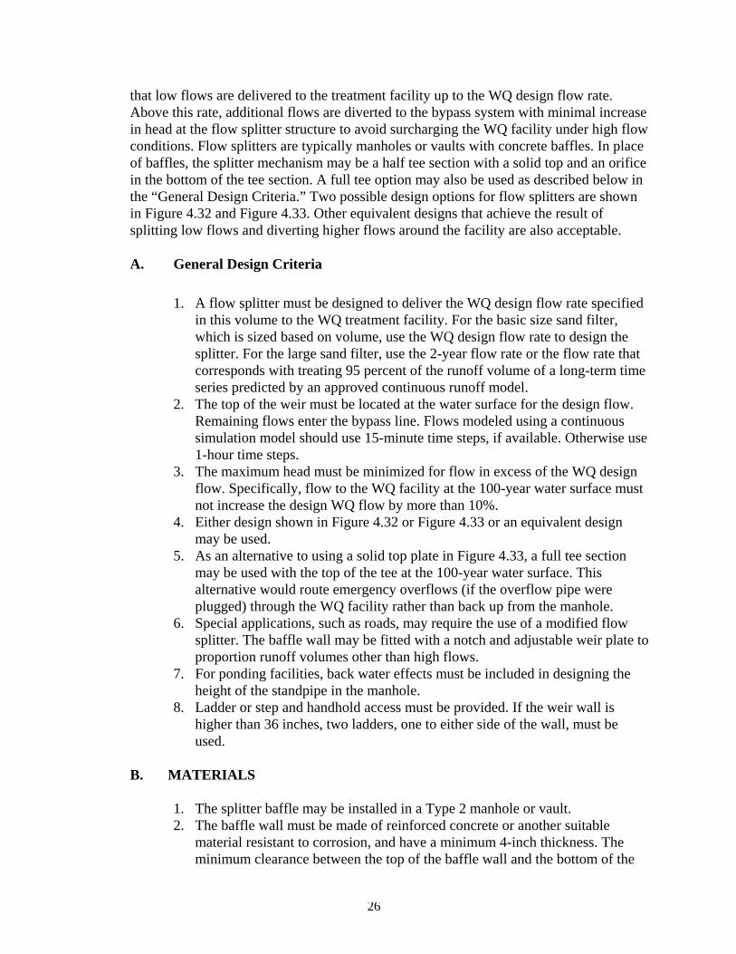
that low flows are delivered to the treatment facility up to the WQ design flow rate. Above this rate, additional flows are diverted to the bypass system with minimal increase in head at the flow splitter structure to avoid surcharging the WQ facility under high flow conditions. Flow splitters are typically manholes or vaults with concrete baffles. In place of baffles, the splitter mechanism may be a half tee section with a solid top and an orifice in the bottom of the tee section. A full tee option may also be used as described below in the “General Design Criteria.” Two possible design options for flow splitters are shown in Figure 4.32 and Figure 4.33. Other equivalent designs that achieve the result of splitting low flows and diverting higher flows around the facility are also acceptable.
A. General Design Criteria
1. A flow splitter must be designed to deliver the WQ design flow rate specified in this volume to the WQ treatment facility. For the basic size sand filter, which is sized based on volume, use the WQ design flow rate to design the splitter. For the large sand filter, use the 2-year flow rate or the flow rate that corresponds with treating 95 percent of the runoff volume of a long-term time series predicted by an approved continuous runoff model.
2. The top of the weir must be located at the water surface for the design flow. Remaining flows enter the bypass line. Flows modeled using a continuous simulation model should use 15-minute time steps, if available. Otherwise use 1-hour time steps.
3. The maximum head must be minimized for flow in excess of the WQ design flow. Specifically, flow to the WQ facility at the 100-year water surface must not increase the design WQ flow by more than 10%.
4. Either design shown in Figure 4.32 or Figure 4.33 or an equivalent design may be used.
5. As an alternative to using a solid top plate in Figure 4.33, a full tee section may be used with the top of the tee at the 100-year water surface. This alternative would route emergency overflows (if the overflow pipe were plugged) through the WQ facility rather than back up from the manhole.
6. Special applications, such as roads, may require the use of a modified flow splitter. The baffle wall may be fitted with a notch and adjustable weir plate to proportion runoff volumes other than high flows.
7. For ponding facilities, back water effects must be included in designing the height of the standpipe in the manhole.
8. Ladder or step and handhold access must be provided. If the weir wall is higher than 36 inches, two ladders, one to either side of the wall, must be used.
B. MATERIALS
1. The splitter baffle may be installed in a Type 2 manhole or vault. 2. The baffle wall must be made of reinforced concrete or another suitable
material resistant to corrosion, and have a minimum 4-inch thickness. The minimum clearance between the top of the baffle wall and the bottom of the
4-26

manhole cover must be 4 feet; otherwise, dual access points should be provided.
3. All metal parts must be corrosion resistant. Examples of preferred materials include aluminum, stainless steel, and plastic. Zinc and galvanized materials are discouraged because of aquatic toxicity. Painted metal parts should not be used because of poor longevity.
4.7.2 Flow Spreading Options Flow spreaders function to uniformly spread flows across the inflow portion of water quality facilities (e.g., sand filter, biofiltration swale, or filter strip). There are five flow spreader options presented in this section:
Option A – Anchored plate Option B – Concrete sump box Option C – Notched curb spreader Option D – Through-curb ports Option E – Interrupted curb
Options A through C can be used for spreading flows that are concentrated. Any one of these options can be used when spreading is required by the facility design criteria. Options A through C can also be used for unconcentrated flows, and in some cases must be used, such as to correct for moderate grade changes along a filter strip. Options D and E are only for flows that are already unconcentrated and enter a filter strip or bioretention system. Other flow spreader options may be possible. A. GENERAL DESIGN CRITERIA
Where flow enters the flow spreader through a pipe, it is recommended that the pipe be submerged to the extent practical to dissipate energy as much as possible. For higher inflows (greater than 5 cfs for the 100-yr storm), a Type 1 catch basin should be positioned in the spreader and the inflow pipe should enter the catch basin with flows exiting through the top grate. The top of the grate should be lower than the level spreader plate, or if a notched spreader is used, lower than the bottom of the v-notches. Option A -- Anchored Plate (See Figure 4.34) 1. An anchored plate flow spreader must be preceded by a sump having a
minimum depth of 8 inches and minimum width of 24 inches. If not otherwise stabilized, the sump area must be lined to reduce erosion and to provide energy dissipation.
2. The top surface of the flow spreader plate must be level, projecting a minimum of 2 inches above the ground surface of the water quality facility, or V-notched with notches 6 to 10 inches on center and 1 to 6 inches deep (use shallower notches with closer spacing). Alternative designs may also be used.
4-27

3. A flow spreader plate must extend horizontally beyond the bottom width of the facility to prevent water from eroding the side slope. The horizontal extent should be such that the bank is protected for all flows up to the 100-year flow or the maximum flow that will enter the Water Quality (WQ) facility.
4. Flow spreader plates must be securely fixed in place. 5. Flow spreader plates may be made of either wood, metal, fiberglass reinforced
plastic, or other durable material. If wood, pressure treated 4 by 10-inch lumber or landscape timbers are acceptable.
6. Anchor posts must be 4-inch square concrete, tubular stainless steel, or other material resistant to decay.
Option B -- Concrete Sump Box (See Figure 4.35) 1. The wall of the downstream side of a rectangular concrete sump box must
extend a minimum of 2 inches above the treatment bed. This serves as a weir to spread the flows uniformly across the bed.
2. The downstream wall of a sump box must have “wing walls” at both ends. Side walls and returns must be slightly higher than the weir so that erosion of the side slope is minimized.
3. Concrete for a sump box can be either cast-in-place or precast, but the bottom of the sump must be reinforced with wire mesh for cast-in-place sumps.
4. Sump boxes must be placed over bases that consists of 4 inches of crushed rock, 5/8-inch minus to help assure the sump remains level.
Option C -- Notched Curb Spreader (Figure 4.36) Notched curb spreader sections must be made of extruded concrete laid side-by-side and level. Typically five “teeth” per four-foot section provide good spacing. The space between adjacent “teeth” forms a v-notch.
Option D -- Through-Curb Ports (Figure 4.37) Unconcentrated flows from paved areas entering filter strips or continuous inflow biofiltration swales can use curb ports or interrupted curbs (Option E) to allow flows to enter the strip or swale. Curb ports use fabricated openings that allow concrete curbing to be poured or extruded while still providing an opening through the curb to admit water to the WQ facility. Openings in the curb must be at regular intervals but at least every 6 feet (minimum). The width of each curb port opening must be a minimum of 11 inches. Approximately 15 percent or more of the curb section length should be in open ports, and no port should discharge more than about 10 percent of the flow.
Option E -- Interrupted Curb (No Figure) Interrupted curbs are sections of curb placed to have gaps spaced at regular intervals along the total width (or length, depending on facility) of the treatment area. At a minimum, gaps must be every 6 feet to allow distribution of flows into the treatment facility before they become too concentrated. The opening must be
4-28

a minimum of 11 inches. As a general rule, no opening should discharge more than 10 percent of the overall flow entering the facility.
4-29