Chapter 4 - Beam Deflections - zmnizam.weebly.com 4 Beam Deflections ... Conjugate Beam Method 5....
27
97 Chapter 4 Beam Deflections 4.1 Introduction When a structure is placed under load it will bend, deflect or displace. The deflection will depend on the following factors: 1. Geometry of the structure, including shape and flexural rigidity of member. 2. Flexibility/rigidity of the material used. 3. Restraint of the supports. 4. Load pattern. In the design of structures the primary requirement is to ensure that the structure or structural component can adequately resist the loading to which it is being subjected. This aspect of design is concerned with designing for strength. However there are other aspects of design that are important, and in the case of the design of beams another consideration is the value of the vertical deflections that will occur when such beam is loaded. This chapter is intended as an introduction to the analytical techniques used for calculating deflections in beams and also for calculating the rotations at critical locations along the length of a beam. 4.2 Deflection of Beams The deformation of a beam is usually expressed in terms of its deflection from its original unloaded position. The deflection is measured from the original neutral surface of the beam to the neutral surface of the deformed beam. The After successfully completing this chapter you should be able to: Develop the general equation for the elastic curve of a deflected beam by using double integration method and area-moment method. State the boundary conditions of a deflected beam Determine the deflections and slopes of elastic curves of simply supported beams and cantilever beams. This chapter will discuss various methods to determine the deflection and slope at the specific points in determinate beam. The methods include the Double Integration method and Macaulay method as well as Moment Area method.
Transcript of Chapter 4 - Beam Deflections - zmnizam.weebly.com 4 Beam Deflections ... Conjugate Beam Method 5....
97
Chapter 4
Beam Deflections 4.1 Introduction When a structure is placed under load it will bend, deflect or displace. The deflection will depend on the following factors:
1. Geometry of the structure, including shape and flexural rigidity of member.
2. Flexibility/rigidity of the material used. 3. Restraint of the supports. 4. Load pattern.
In the design of structures the primary requirement is to ensure that the structure or structural component can adequately resist the loading to which it is being subjected. This aspect of design is concerned with designing for strength. However there are other aspects of design that are important, and in the case of the design of beams another consideration is the value of the vertical deflections that will occur when such beam is loaded. This chapter is intended as an introduction to the analytical techniques used for calculating deflections in beams and also for calculating the rotations at critical locations along the length of a beam. 4.2 Deflection of Beams The deformation of a beam is usually expressed in terms of its deflection from its original unloaded position. The deflection is measured from the original neutral surface of the beam to the neutral surface of the deformed beam. The
After successfully completing this chapter you should be able to:
Develop the general equation for the elastic curve of a deflected beam by using double integration method and area-moment method.
State the boundary conditions of a deflected beam
Determine the deflections and slopes of elastic curves of simply supported beams and cantilever beams.
This chapter will discuss various methods to determine the deflection and slope at the specific points in determinate beam. The methods include the Double Integration method and Macaulay method as well as Moment Area method.
98
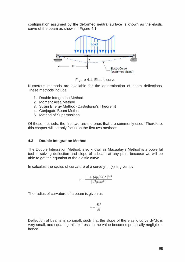
configuration assumed by the deformed neutral surface is known as the elastic curve of the beam as shown in Figure 4.1.
Figure 4.1: Elastic curve
Numerous methods are available for the determination of beam deflections. These methods include:
1. Double Integration Method 2. Moment Area Method 3. Strain Energy Method (Castigliano’s Theorem) 4. Conjugate Beam Method 5. Method of Superposition
Of these methods, the first two are the ones that are commonly used. Therefore, this chapter will be only focus on the first two methods. 4.3 Double Integration Method The Double Integration Method, also known as Macaulay’s Method is a powerful tool in solving deflection and slope of a beam at any point because we will be able to get the equation of the elastic curve. In calculus, the radius of curvature of a curve y = f(x) is given by
The radius of curvature of a beam is given as
Deflection of beams is so small, such that the slope of the elastic curve dy/dx is very small, and squaring this expression the value becomes practically negligible, hence
99
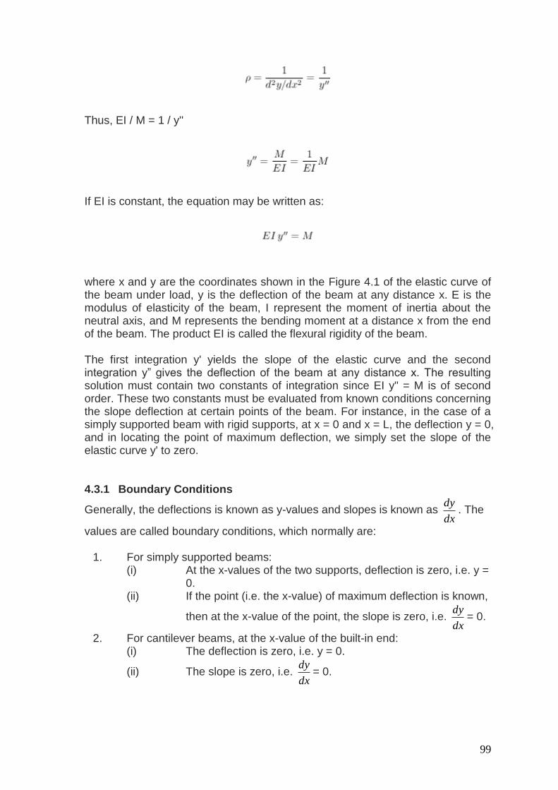
Thus, EI / M = 1 / y''
If EI is constant, the equation may be written as:
where x and y are the coordinates shown in the Figure 4.1 of the elastic curve of the beam under load, y is the deflection of the beam at any distance x. E is the modulus of elasticity of the beam, I represent the moment of inertia about the neutral axis, and M represents the bending moment at a distance x from the end of the beam. The product EI is called the flexural rigidity of the beam. The first integration y' yields the slope of the elastic curve and the second integration y” gives the deflection of the beam at any distance x. The resulting solution must contain two constants of integration since EI y" = M is of second order. These two constants must be evaluated from known conditions concerning the slope deflection at certain points of the beam. For instance, in the case of a simply supported beam with rigid supports, at x = 0 and x = L, the deflection y = 0, and in locating the point of maximum deflection, we simply set the slope of the elastic curve y' to zero. 4.3.1 Boundary Conditions
Generally, the deflections is known as y-values and slopes is known as dx
dy. The
values are called boundary conditions, which normally are:
1. For simply supported beams: (i) At the x-values of the two supports, deflection is zero, i.e. y =
0. (ii) If the point (i.e. the x-value) of maximum deflection is known,
then at the x-value of the point, the slope is zero, i.e. dx
dy= 0.
2. For cantilever beams, at the x-value of the built-in end: (i) The deflection is zero, i.e. y = 0.
(ii) The slope is zero, i.e. dx
dy= 0.
100
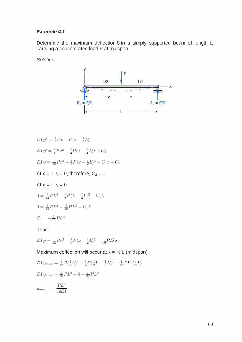
Example 4.1 Determine the maximum deflection δ in a simply supported beam of length L carrying a concentrated load P at midspan. Solution:
At x = 0, y = 0, therefore, C2 = 0 At x = L, y = 0
Thus,
Maximum deflection will occur at x = ½ L (midspan)
101
The negative sign indicates that the deflection is below the undeformed neutral axis. Therefore,
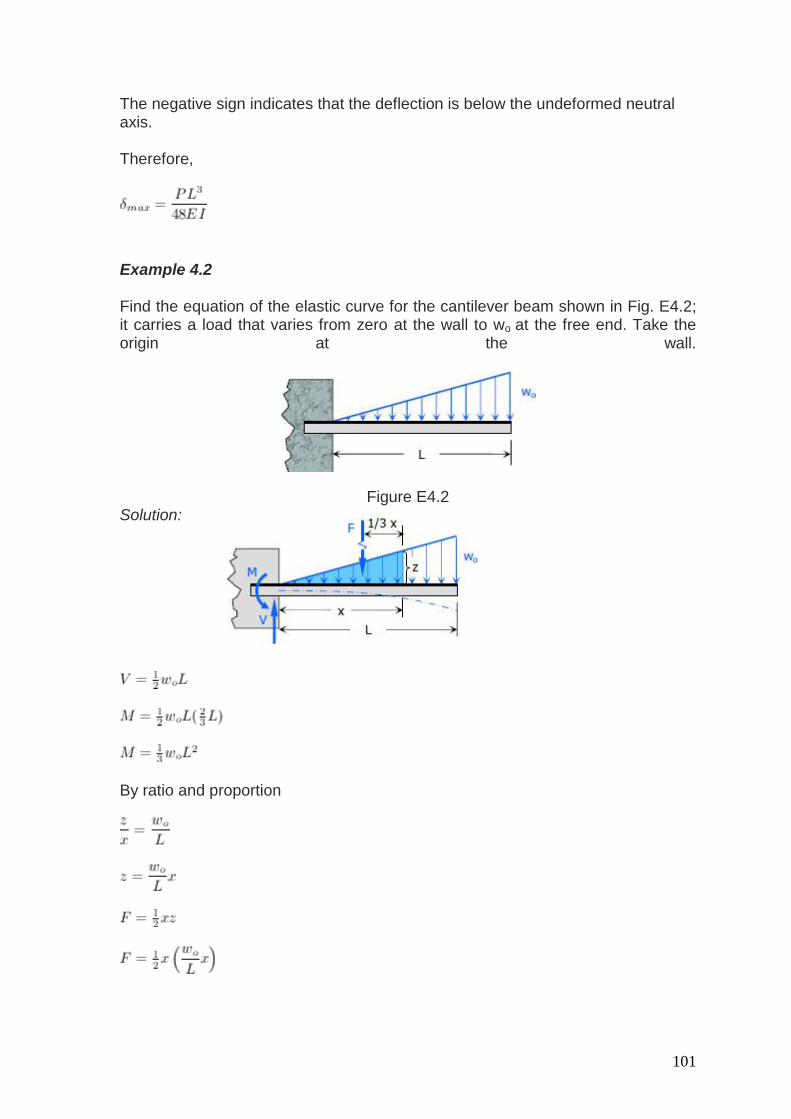
Example 4.2 Find the equation of the elastic curve for the cantilever beam shown in Fig. E4.2; it carries a load that varies from zero at the wall to wo at the free end. Take the origin at the wall.
Figure E4.2 Solution:
By ratio and proportion
102
At x = 0, y' = 0, therefore C1 = 0 At x = 0, y = 0, therefore C2 = 0 Therefore, the equation of the elastic curve is
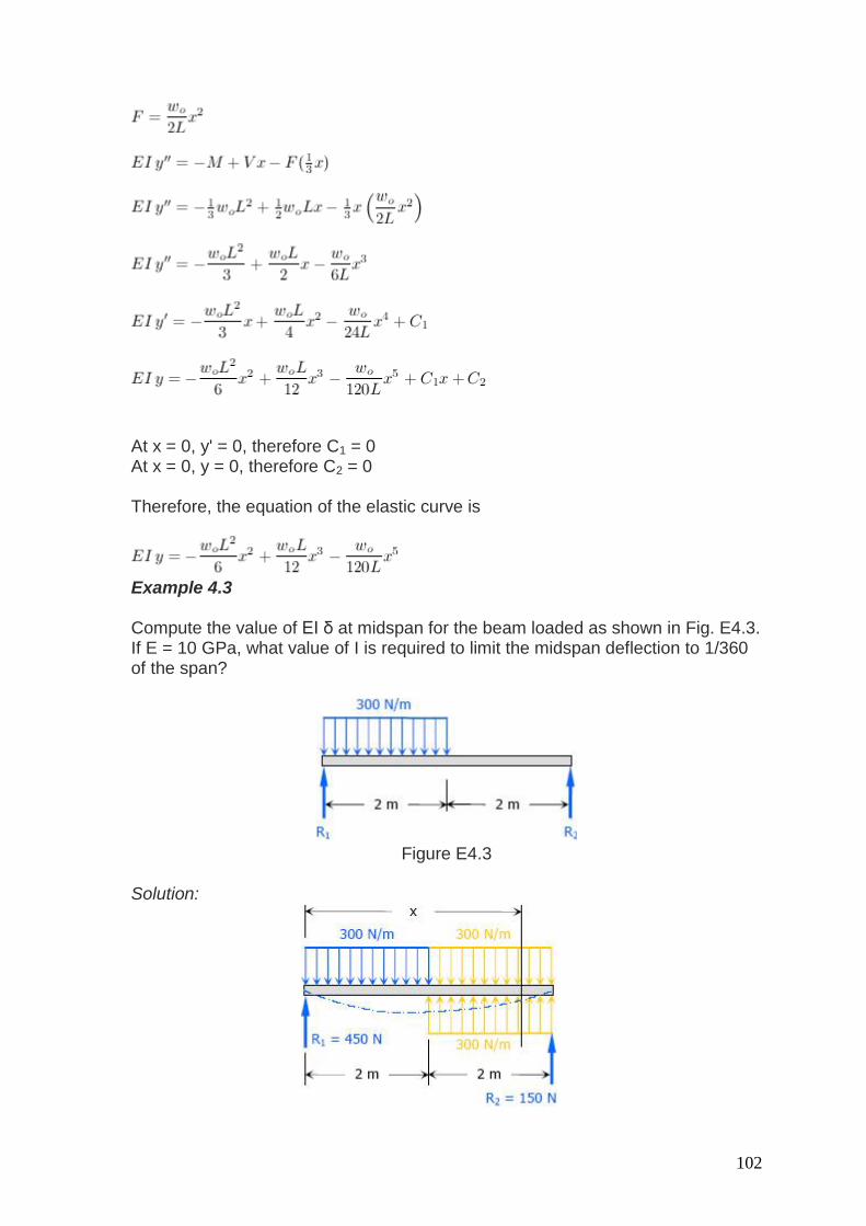
Example 4.3 Compute the value of EI δ at midspan for the beam loaded as shown in Fig. E4.3. If E = 10 GPa, what value of I is required to limit the midspan deflection to 1/360 of the span?
Figure E4.3
Solution:
103
At x = 0, y = 0, therefore C2 = 0 At x = 4 m, y = 0
Therefore,
At x = 2 m (midspan)
Maximum midspan deflection
Thus,
104
or
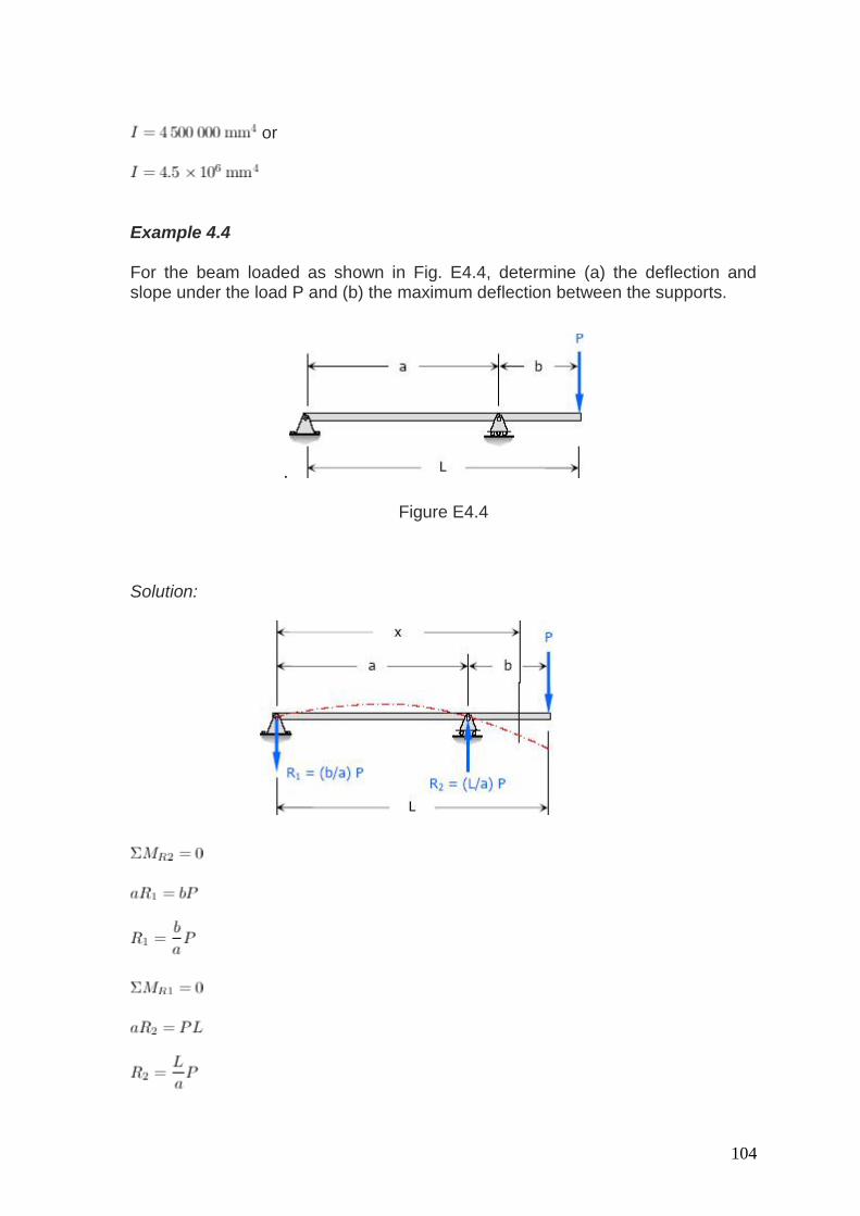
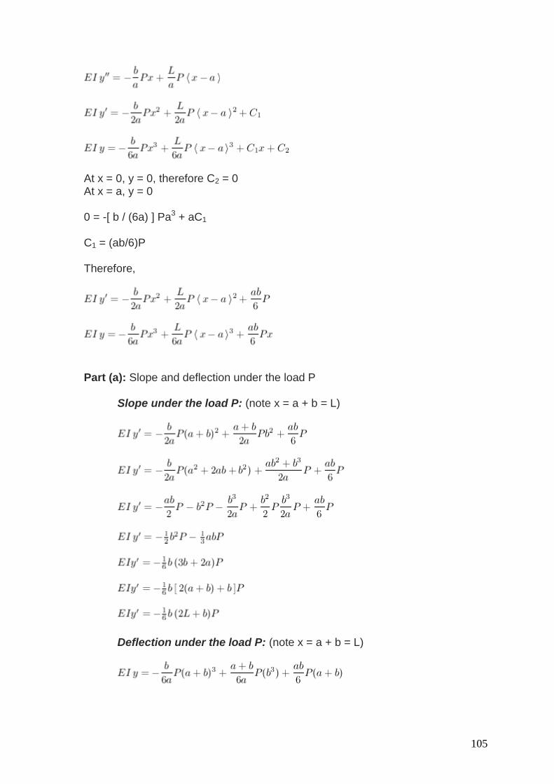
Example 4.4 For the beam loaded as shown in Fig. E4.4, determine (a) the deflection and slope under the load P and (b) the maximum deflection between the supports.
.
Figure E4.4
Solution:
105
At x = 0, y = 0, therefore C2 = 0 At x = a, y = 0 0 = -[ b / (6a) ] Pa3 + aC1
C1 = (ab/6)P Therefore,
Part (a): Slope and deflection under the load P
Slope under the load P: (note x = a + b = L)
Deflection under the load P: (note x = a + b = L)
106
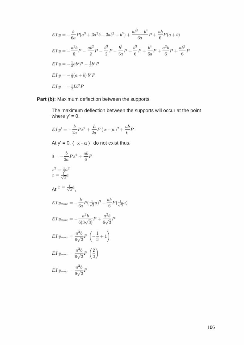
Part (b): Maximum deflection between the supports
The maximum deflection between the supports will occur at the point where y' = 0.
At y' = 0, ⟨ x - a ⟩ do not exist thus,
At ,
107
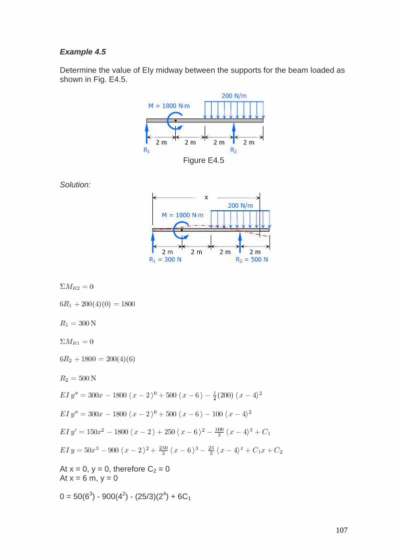
Example 4.5 Determine the value of EIy midway between the supports for the beam loaded as shown in Fig. E4.5.
Figure E4.5
Solution:
At x = 0, y = 0, therefore C2 = 0 At x = 6 m, y = 0 0 = 50(63) - 900(42) - (25/3)(24) + 6C1
108
C1 = 5600/9 N·m3 Therefore,
At x = 3 m
4.4 Moment Diagrams by Parts The moment-area method of finding the deflection of a beam will demand the accurate computation of the area of a moment diagram, as well as the moment of such area about any axis. To pave its way, this section will deal on how to draw moment diagrams by parts and to calculate the moment of such diagrams about a specified axis. 4.4.1 Basic Principles
1. The bending moment caused by all forces to the left or to the right of any section is equal to the respective algebraic sum of the bending moments at that section caused by each load acting separately.
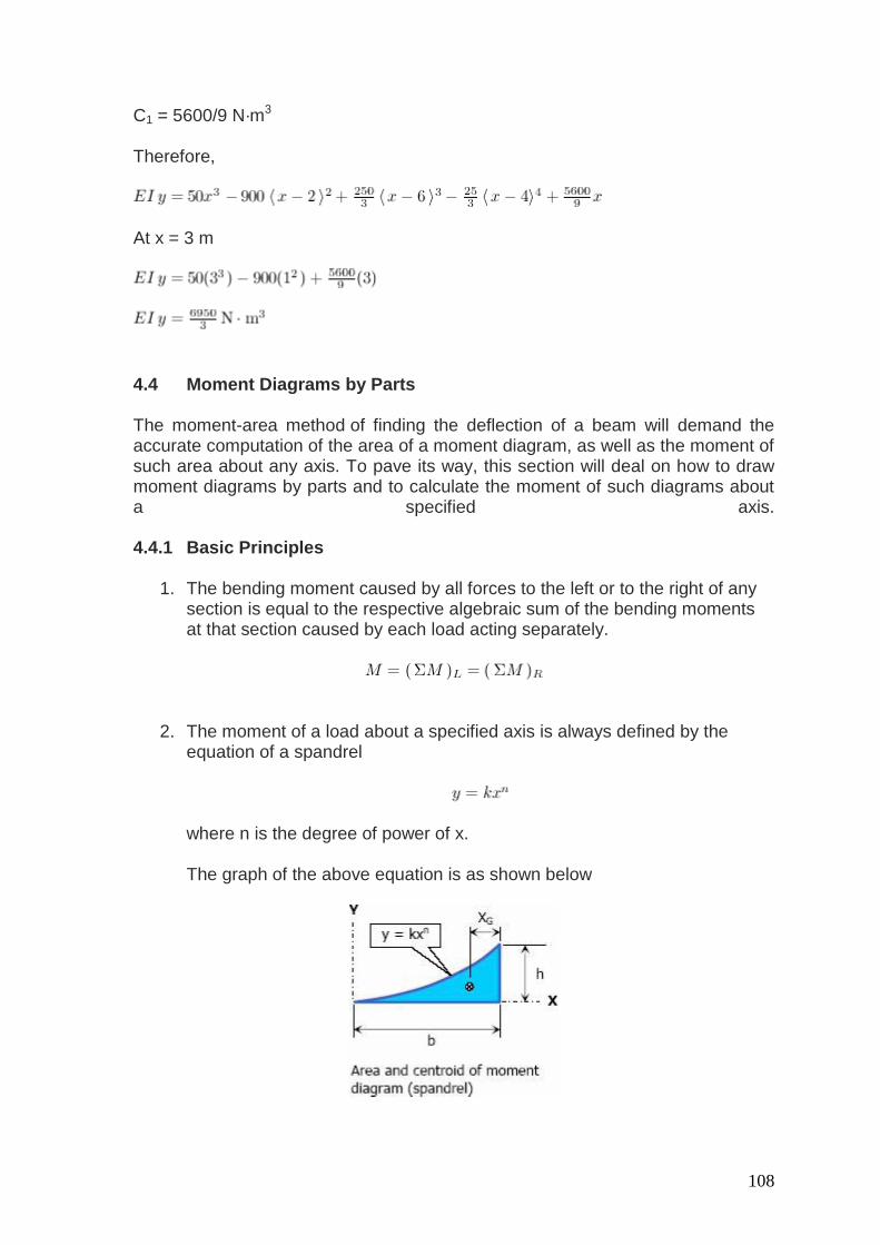
2. The moment of a load about a specified axis is always defined by the
equation of a spandrel
where n is the degree of power of x.
The graph of the above equation is as shown below
109
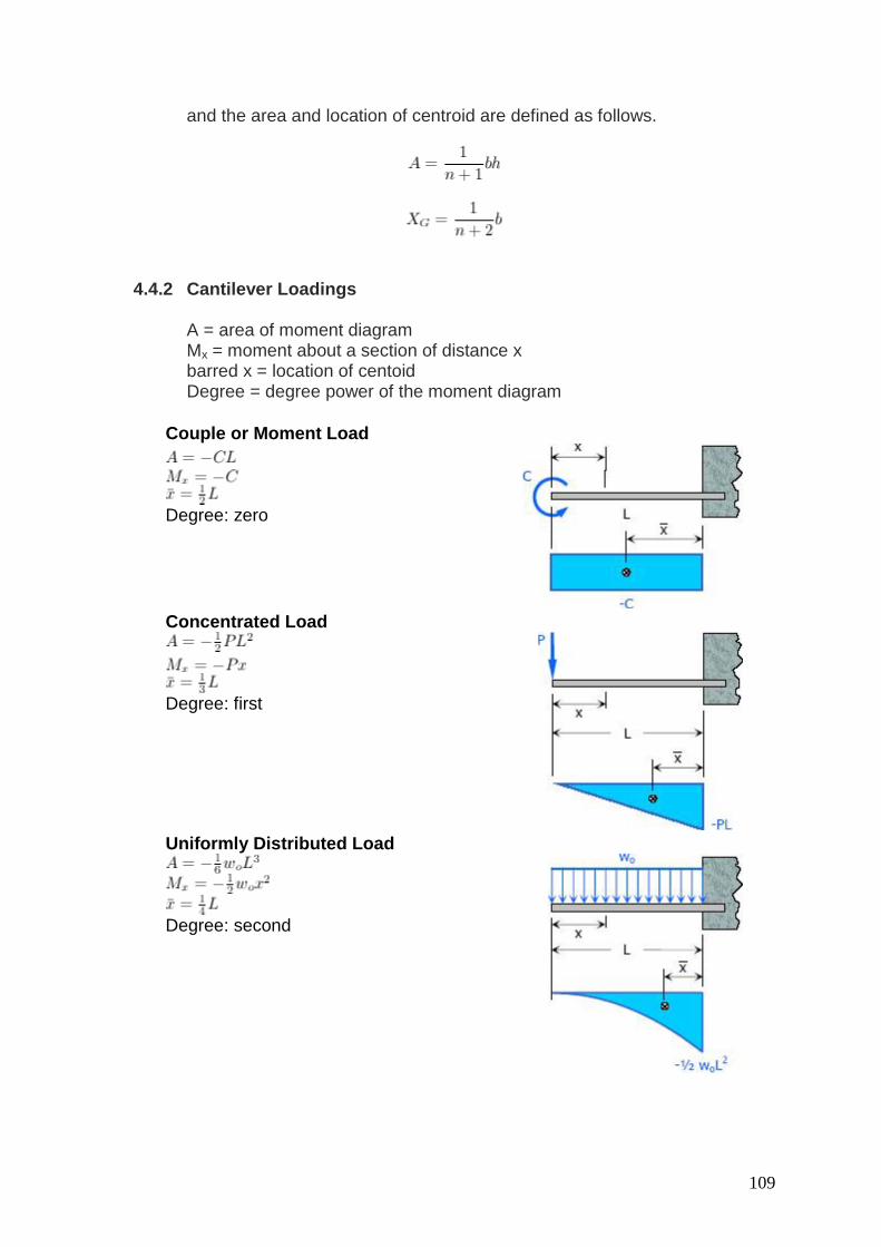
and the area and location of centroid are defined as follows.
4.4.2 Cantilever Loadings
A = area of moment diagram Mx = moment about a section of distance x barred x = location of centoid Degree = degree power of the moment diagram
Couple or Moment Load
Degree: zero
Concentrated Load
Degree: first
Uniformly Distributed Load
Degree: second
110
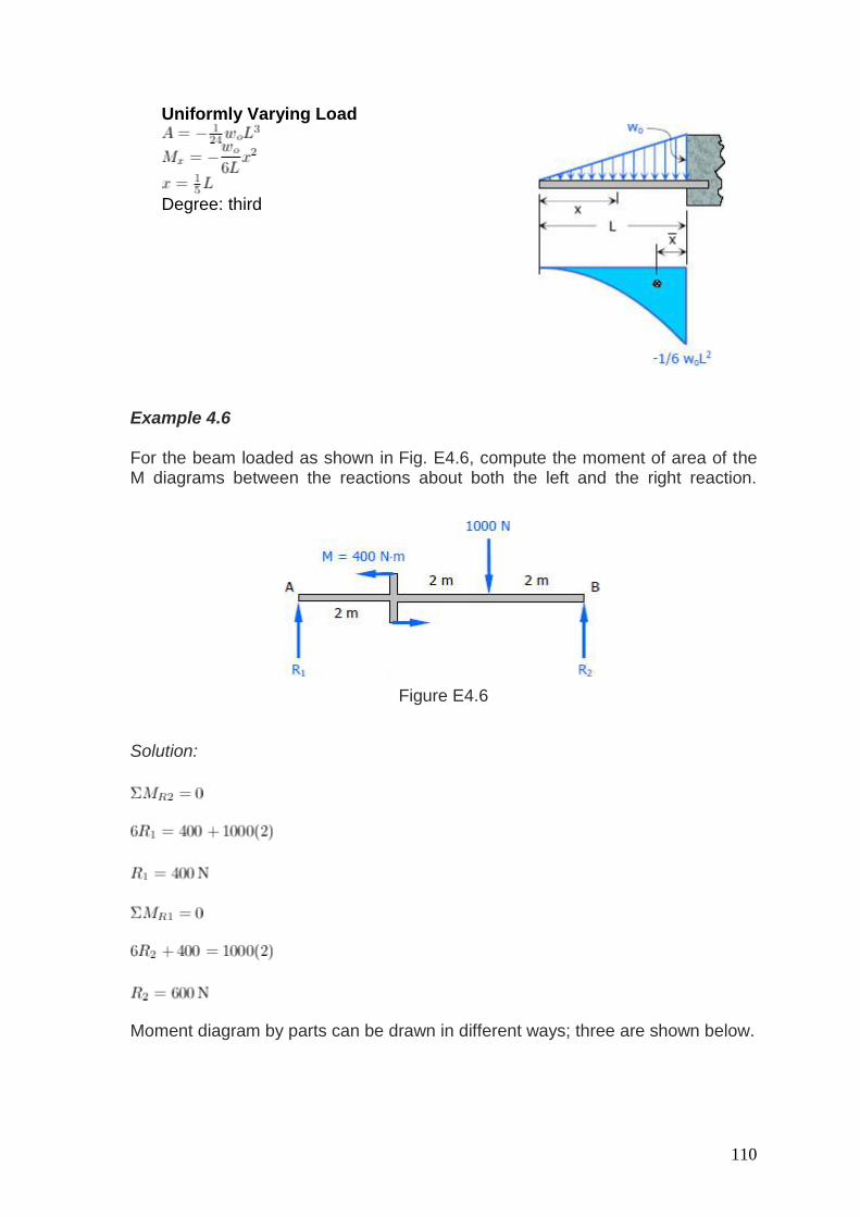
Uniformly Varying Load
Degree: third
Example 4.6 For the beam loaded as shown in Fig. E4.6, compute the moment of area of the M diagrams between the reactions about both the left and the right reaction.
Figure E4.6
Solution:
Moment diagram by parts can be drawn in different ways; three are shown below.
111
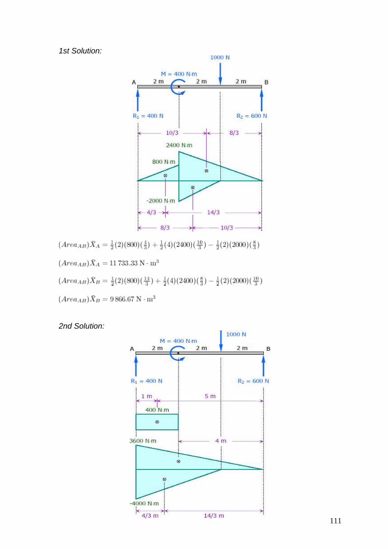
1st Solution:
2nd Solution:
112
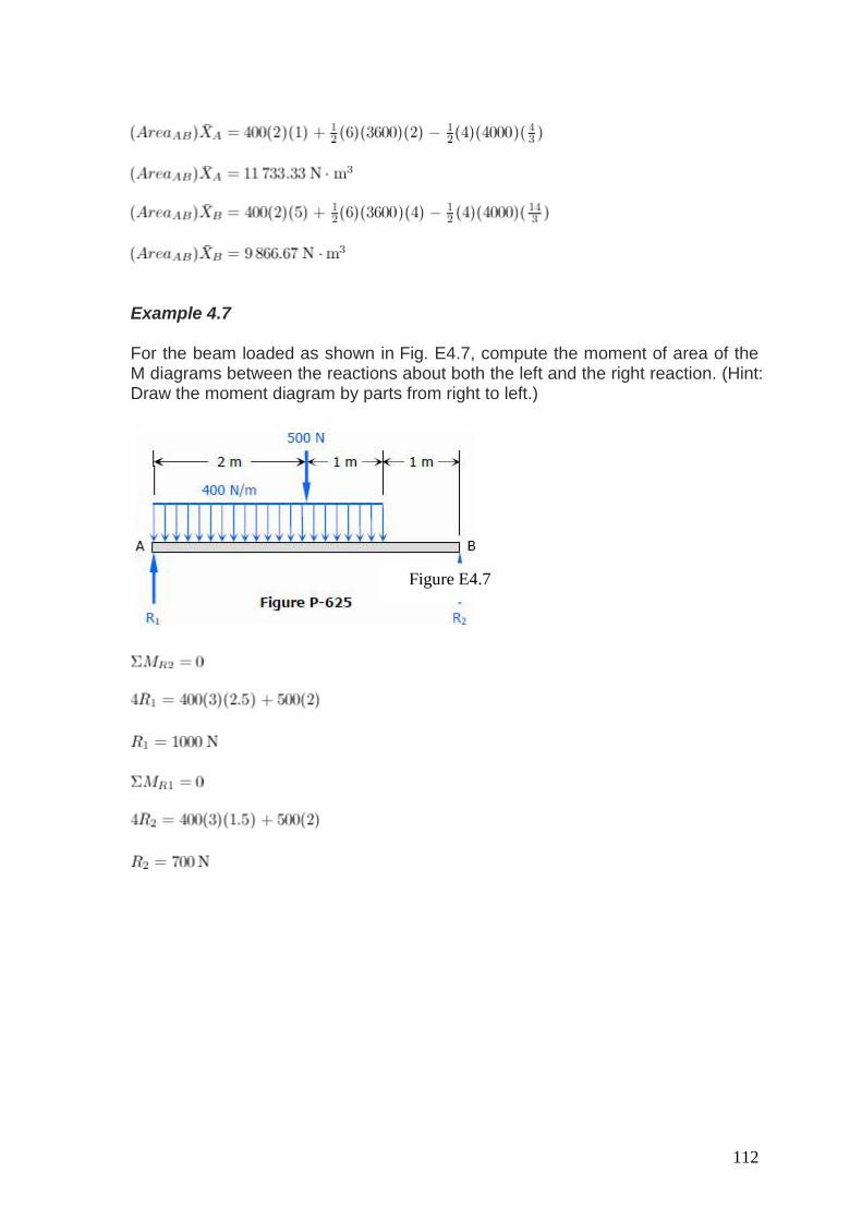
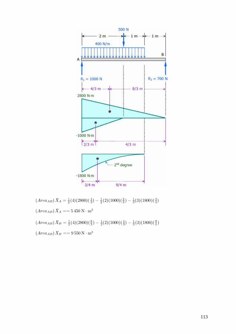
Example 4.7 For the beam loaded as shown in Fig. E4.7, compute the moment of area of the M diagrams between the reactions about both the left and the right reaction. (Hint: Draw the moment diagram by parts from right to left.)
Figure E4.7
113
114
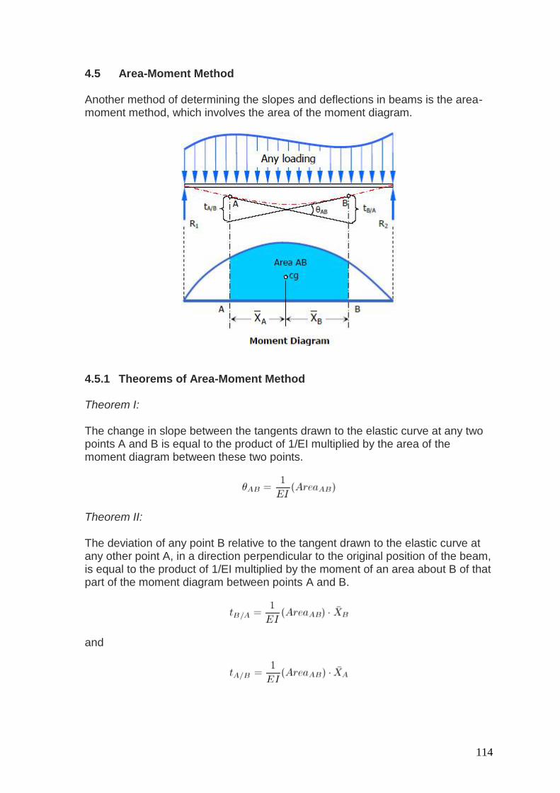
4.5 Area-Moment Method Another method of determining the slopes and deflections in beams is the area-moment method, which involves the area of the moment diagram.
4.5.1 Theorems of Area-Moment Method Theorem I: The change in slope between the tangents drawn to the elastic curve at any two points A and B is equal to the product of 1/EI multiplied by the area of the moment diagram between these two points.
Theorem II: The deviation of any point B relative to the tangent drawn to the elastic curve at any other point A, in a direction perpendicular to the original position of the beam, is equal to the product of 1/EI multiplied by the moment of an area about B of that part of the moment diagram between points A and B.
and
115
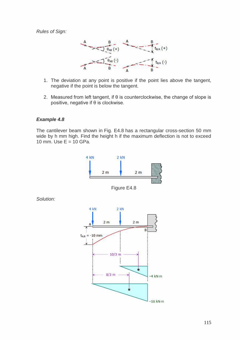
Rules of Sign:
1. The deviation at any point is positive if the point lies above the tangent, negative if the point is below the tangent.
2. Measured from left tangent, if θ is counterclockwise, the change of slope is
positive, negative if θ is clockwise. Example 4.8 The cantilever beam shown in Fig. E4.8 has a rectangular cross-section 50 mm wide by h mm high. Find the height h if the maximum deflection is not to exceed 10 mm. Use E = 10 GPa.
Figure E4.8
Solution:
116
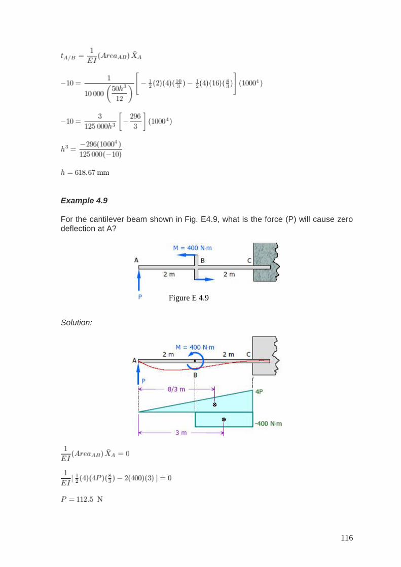
Example 4.9 For the cantilever beam shown in Fig. E4.9, what is the force (P) will cause zero deflection at A?
Solution:
Figure E 4.9
117
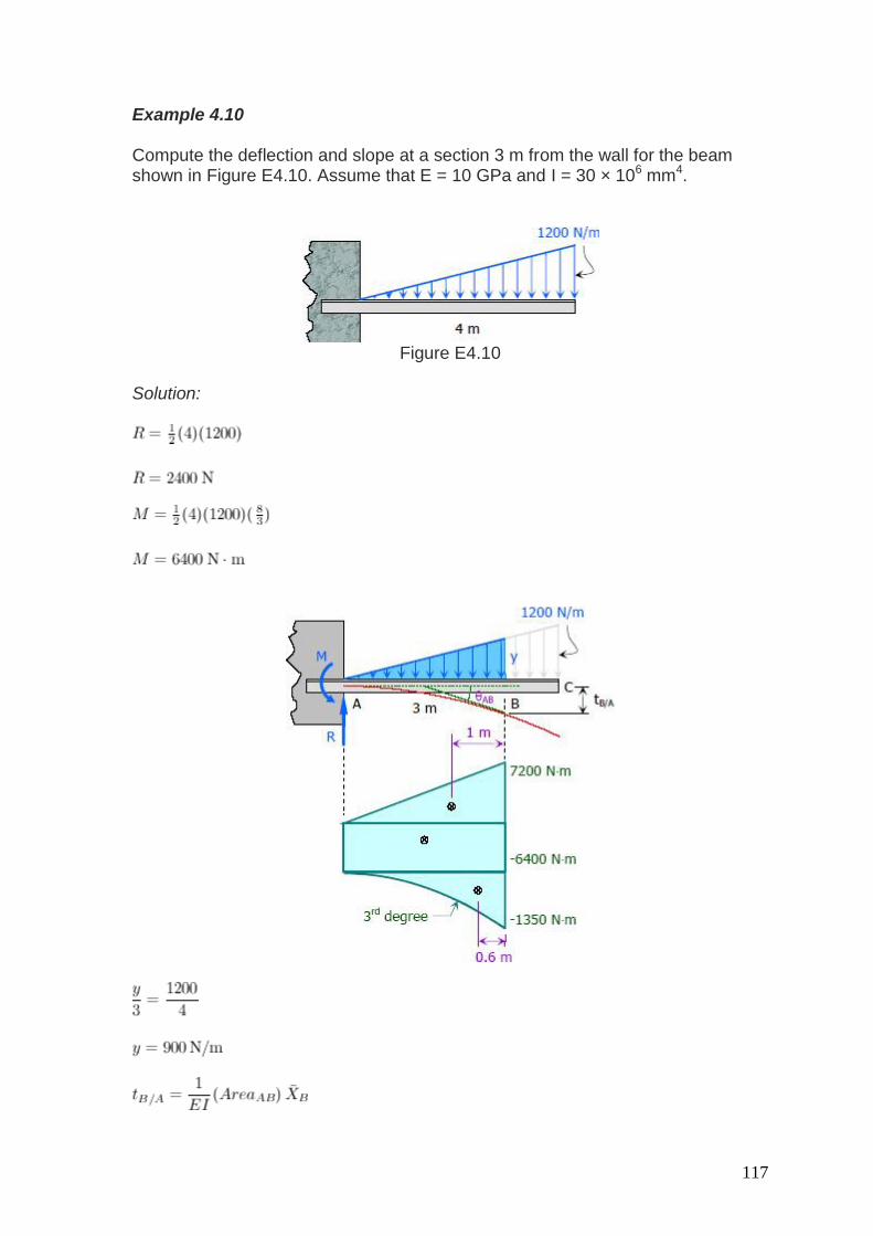
Example 4.10 Compute the deflection and slope at a section 3 m from the wall for the beam shown in Figure E4.10. Assume that E = 10 GPa and I = 30 × 106 mm4.
Figure E4.10
Solution:
118
Therefore:
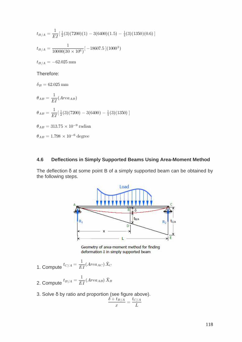
4.6 Deflections in Simply Supported Beams Using Area-Moment Method The deflection δ at some point B of a simply supported beam can be obtained by the following steps.
1. Compute
2. Compute 3. Solve δ by ratio and proportion (see figure above).
119
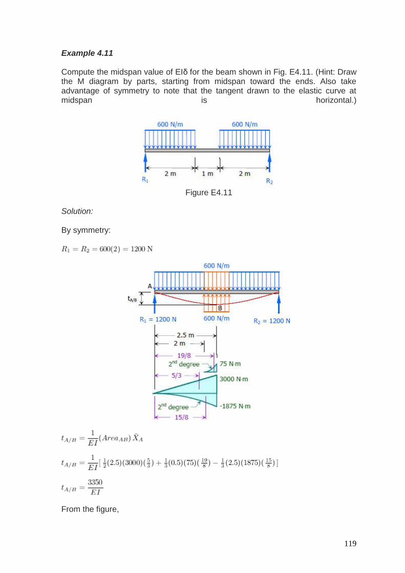
Example 4.11 Compute the midspan value of EIδ for the beam shown in Fig. E4.11. (Hint: Draw the M diagram by parts, starting from midspan toward the ends. Also take advantage of symmetry to note that the tangent drawn to the elastic curve at midspan is horizontal.)
Figure E4.11
Solution:
By symmetry:
From the figure,

120
Thus
Example 4.12 A simple beam supports a concentrated load placed anywhere on the span, as shown in Fig. E4.12. Measuring x from A, show that the maximum deflection occurs at x = √[(L2 - b2)/3].
Figure E4.12
Solution:

121
From the figure:
122
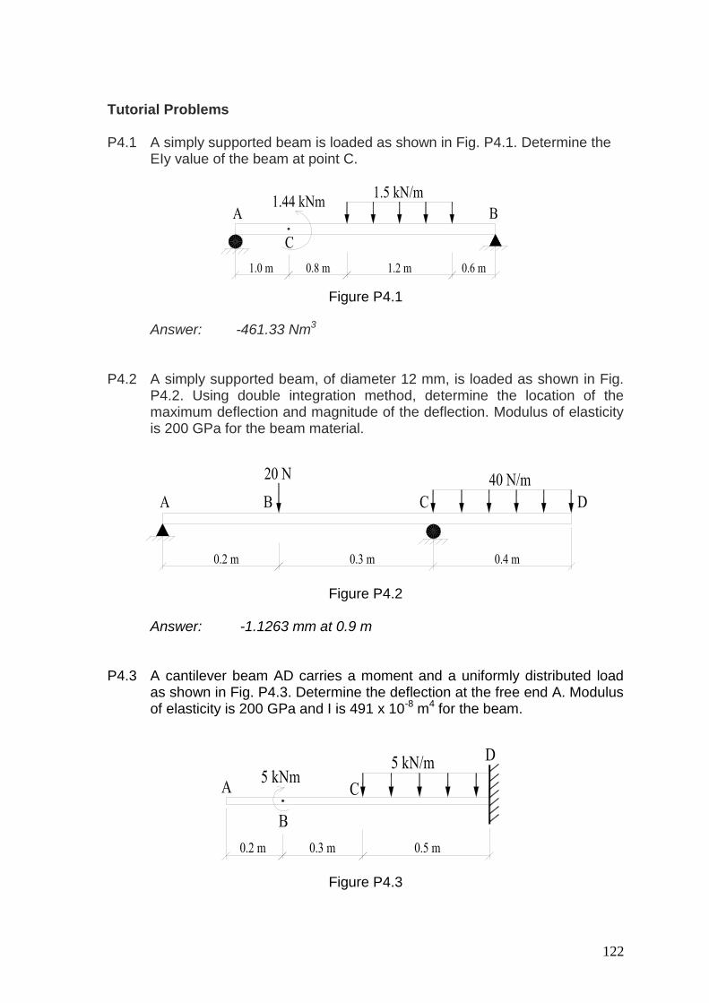
Tutorial Problems P4.1 A simply supported beam is loaded as shown in Fig. P4.1. Determine the
EIy value of the beam at point C.
Figure P4.1
Answer: -461.33 Nm3 P4.2 A simply supported beam, of diameter 12 mm, is loaded as shown in Fig.
P4.2. Using double integration method, determine the location of the maximum deflection and magnitude of the deflection. Modulus of elasticity is 200 GPa for the beam material.
Figure P4.2
Answer: -1.1263 mm at 0.9 m
P4.3 A cantilever beam AD carries a moment and a uniformly distributed load
as shown in Fig. P4.3. Determine the deflection at the free end A. Modulus of elasticity is 200 GPa and I is 491 x 10-8 m4 for the beam.
Figure P4.3
123
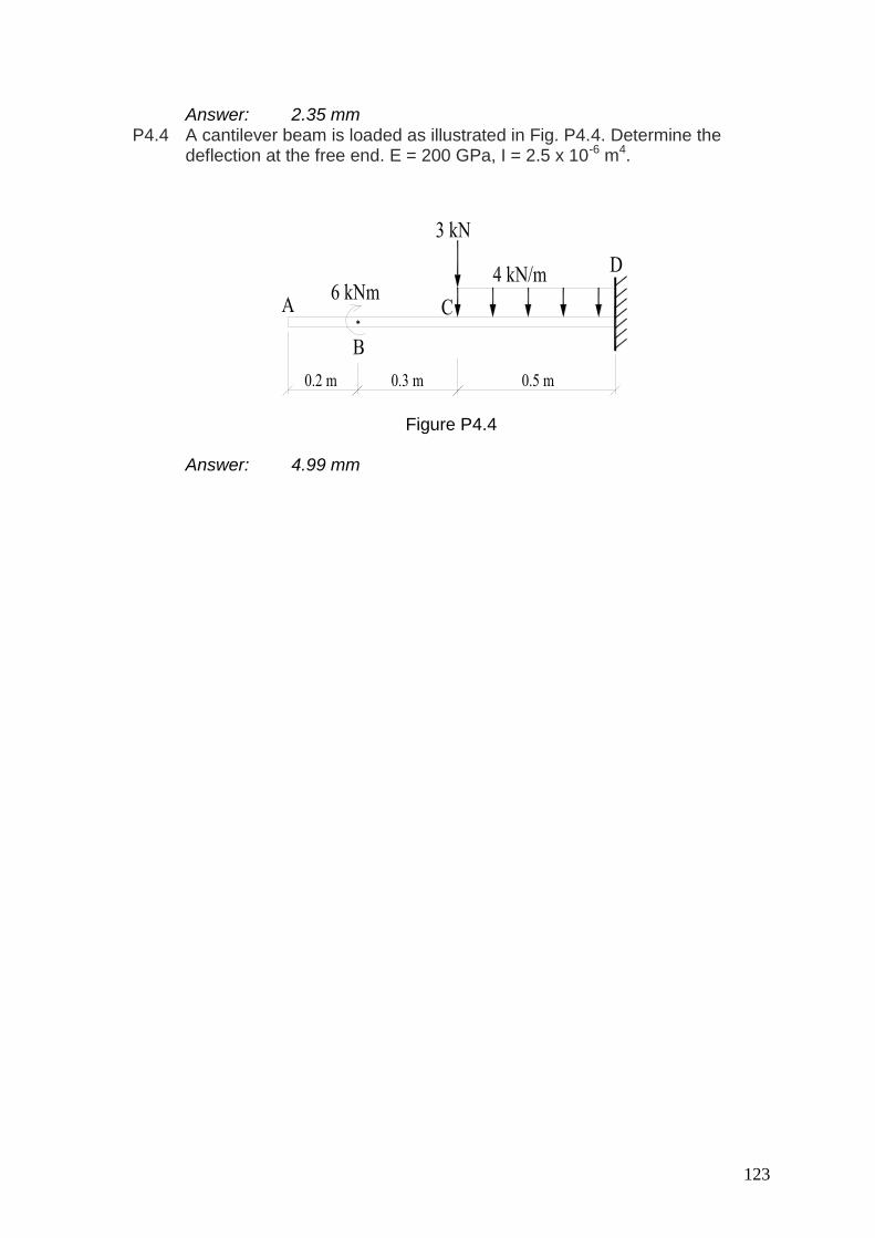
Answer: 2.35 mm P4.4 A cantilever beam is loaded as illustrated in Fig. P4.4. Determine the
deflection at the free end. E = 200 GPa, I = 2.5 x 10⁻⁶ m4.
Figure P4.4
Answer: 4.99 mm