Chapter 4: A Look at Membrane and Thin Plate Theory performed today. Hencky (1921) worked rigorously...
25
83 Chapter 4: A Look at Membrane and Thin Plate Theory 4.1 Introduction The key to designing an effective controller for an ultra-large, ultra-flexible optic is the accurate modeling of the system dynamics present. An accurate model helps the control engineer to understand the fundamental states of the system, such as locations of maximum strain, acceleration, or velocity, to name but a few. By understanding the locations and magnitudes of the system states through a well-developed model, a controller well-suited to the undesirable dynamical states of the system can be designed, tested, and implemented to create a desirable system. Of primary concern with regards to the space optic is the nature of its dynamics—is it a thin plate or a membrane? Our choice in this regard will have a significant impact on the type of sensors and actuators suitable for optical level control of the imaging surface. Further, our choice will also have significant consequences on the type and extent of dynamics possible from our model of the imaging surface. The following sections will outline a brief history on the development of thin plate and membrane theory, and then conclusions will be drawn to discern the best modeling medium for the dynamics governing a large, flexible space optic. 4.2 History of the Development of Plate Theory Tracing the family tree of plate theory to its roots, one travels back to the American Revolution time period and finds Euler performing free vibration analyses of plate problems (Euler, 1766). Chladni, a German physicist, performed experiments on horizontal plates to quantify their vibratory modes. He sprinkled sand on the plates, struck them with a hammer, and noted the regular patterns that formed along the nodal lines (Chladni, 1802). Bernoulli then attempted to theoretically justify the experimental results of Chladni using the previously developed Euler-Bernoulli bending beam theory, but his results did not capture the full dynamics (Bernoulli, 1789). The French
Transcript of Chapter 4: A Look at Membrane and Thin Plate Theory performed today. Hencky (1921) worked rigorously...

83
Chapter 4: A Look at Membrane and Thin Plate
Theory
4.1 Introduction
The key to designing an effective controller for an ultra-large, ultra-flexible optic is the
accurate modeling of the system dynamics present. An accurate model helps the control
engineer to understand the fundamental states of the system, such as locations of
maximum strain, acceleration, or velocity, to name but a few. By understanding the
locations and magnitudes of the system states through a well-developed model, a
controller well-suited to the undesirable dynamical states of the system can be designed,
tested, and implemented to create a desirable system.
Of primary concern with regards to the space optic is the nature of its dynamics—is it a
thin plate or a membrane? Our choice in this regard will have a significant impact on the
type of sensors and actuators suitable for optical level control of the imaging surface.
Further, our choice will also have significant consequences on the type and extent of
dynamics possible from our model of the imaging surface. The following sections will
outline a brief history on the development of thin plate and membrane theory, and then
conclusions will be drawn to discern the best modeling medium for the dynamics
governing a large, flexible space optic.
4.2 History of the Development of Plate Theory
Tracing the family tree of plate theory to its roots, one travels back to the American
Revolution time period and finds Euler performing free vibration analyses of plate
problems (Euler, 1766). Chladni, a German physicist, performed experiments on
horizontal plates to quantify their vibratory modes. He sprinkled sand on the plates,
struck them with a hammer, and noted the regular patterns that formed along the nodal
lines (Chladni, 1802). Bernoulli then attempted to theoretically justify the experimental
results of Chladni using the previously developed Euler-Bernoulli bending beam theory,
but his results did not capture the full dynamics (Bernoulli, 1789). The French

84
mathematician Germain developed a plate differential equation that lacked a warping
term (Germain, 1826), but one of the reviewers of her work, Lagrange (1828), corrected
Germain’s results; “thus, he was the first person to present the general plate equation
properly” (Ventsel and Krauthammer, 2001).
Cauchy (1828) and Poisson (1829) developed the problem of plate bending using general
theory of elasticity. Then, in 1829, Poisson successfully expanded “the Germain-
Lagrange plate equation to the solution of a plate under static loading. In this solution,
however, the plate flexural rigidity D was set equal to a constant term” (Ventsel and
Krauthammer, 2001). Navier (1823) considered the plate thickness in the general plate
equation as a function of rigidity, D.
Some of the greatest contributions toward thin plate theory came from Kirchhoff’s thesis
in 1850 (Kirchhoff, 1850). Kirchhoff declared some basic assumptions that are now
referred to as “Kirchhoff’s hypotheses.” Using these assumptions, Kirchhoff: simplified
the energy functional for 3D plates; demonstrated, under certain conditions, the Germain-
Lagrange equation as the Euler equation; and declared that plate edges can only support
two boundary conditions (Ventsel and Krauthammer, 2001). Lord Kelvin (Thompson)
and Tait (1883) showed that plate edges are subject to only shear and moment forces.
Kirchhoff’s hypotheses are fundamental assumptions in the development of linear,
elastic, small-deflection theory for the bending of thin plates. These assumptions are re-
stated here from Ventsel and Krauthammer (2001):
1. The material of the plate is elastic, homogenous, and isotropic.
2. The plate is initially flat.
3. The deflection (the normal component of the displacement vector) of the midplane
is small compared with the thickness of the plate. The slope of the deflected
surface is therefore very small and the square of the slope is a negligible quantity
in comparison with unity.

85
4. The straight lines, initially normal to the middle plane before bending, remain
straight and normal to the middle surface during the deformation, and the length
of such elements is not altered. This means that the vertical shear strains γxy and
γyz are negligible and the normal strain εz may also be omitted. This assumption is
referred to as the “hypothesis of straight normals.”
5. The stress normal to the middle plane, σz, is small compared with the other stress
components and may be neglected in the stress-strain relations.
6. Since the displacements of the plate are small, it is assumed that the middle
surface remains unstrained after bending.
These points, 1 – 6, are the foundation for plate bending theory that is usually referred to
as the classical or Kirchhoff’s plate theory. Figure 4.1 shows a representative plate
geometry.
Figure 4.1. Sample plate geometry showing the midplane, or middle surface, and
typical Cartesian coordinate axes.
Thin plates are usually characterized by the ratio a / h (the ratio between the length of a
side, a, and the thickness of the material, h, falling between the values of 8 and 80
2h
x(u)
z(w)
y(v)
midplane
midplane (after deformation)

86
(Ventsel and Krauthammer, 2001). Under Kirchhoff’s hypotheses, the governing
equation of motion can be derived for small deflections in thin plates as:
2
2
4
4
22
4
4
4 ),,(),,(),,(2),,(t
tyxwhy
tyxwyx
tyxwx
tyxwD∂
∂=
∂
∂+
∂∂∂
+∂
∂ ρ (4.1)
where w(x,y,t) is the deflection of the plate, ρ is the density, h is the plate’s thickness, and
D is the flexural rigidity of the plate. Sometimes, Equation 4.1 is written as
),,(),,(4 tyxhwtyxw ttρ=∇ (4.2)
where, in Cartesian coordinates,
4
4
22
4
4
44 2)(
yyxx ∂∂
+∂∂∂
+∂∂
≡⋅∇ . (4.3)
)(4 ⋅∇ is called the biharmonic operator.
Levy (1899) successfully solved the rectangular plate problem of two parallel edges
simply-supported with the other two edges of arbitrary boundary condition. Meanwhile,
in Russia, Bubnov (1914) investigated the theory of flexible plates, and was the first to
introduce a plate classification system. Bubnov composed tables “of maximum
deflections and maximum bending moments for plates of various properties” (Ventsel
and Krauthammer, 2001). Galerkin (1933) then further developed Bubnov’s theory and
applied it to various bending problems for plates of arbitrary geometries.
Timoshenko (1913, 1915) provided a further boost to the theory of plate bending
analysis; most notably, his solutions to problems considering large deflections in circular
plates and his development of elastic stability problems. Timoshenko and Woinowsky-
Krieger (1959) wrote a textbook that is fundamental to most plate bending analysis

87
performed today. Hencky (1921) worked rigorously on the theory of large deformations
and the general theory of elastic stability of thin plates. Föppl (1951) simplified the
general equations for the large deflections of very thin plates. The final form of the large
deflection thin plate theory was stated by von Karman, who had performed extensive
research in this area previously (1910). The von Karman equations (1910) governing the
large deflections of thin plates are given by:
∂∂
∂∂∂Φ∂
−∂∂
∂Φ∂
+∂∂
∂Φ∂
+=∂∂
+∂∂
∂+
∂∂
∂∂
∂∂
−
∂∂
∂=
∂Φ∂
+∂∂Φ∂
+∂Φ∂
yxw
yxyw
xxw
yp
Dyw
yxw
xw
yw
xw
yxwEh
yyxx22
2
2
2
2
2
2
2
2
4
4
22
4
4
4
2
2
2
222
4
4
22
4
4
4
212
2 (4.4)
where w(x,y) is the deflection of the plate, Φ is the stress function, E is the Young’s
modulus, h is the plate’s thickness, p is an applied pressure, and D is the flexural rigidity.
These equations are coupled, non-linear, partial differential equations, both of which are
fourth order. Unfortunately, this also makes them extremely difficult to solve
analytically. For the present time, we will limit our discussion to Kirchhoff’s plate
theory.
4.3 Development of Membrane Theory
Membranes could be considered a simplified plate, and hence, formal theory of
membrane mechanics developed concurrently with the theory of thin plates. A primary
indication of membrane dynamics is given by the ratio a / h falling between 80 and 100.
In 1907, Föppl derived equilibrium equations for a membrane plate. Essentially, Föppl’s
derived equations were modified von Karman plate equations (Equations 4.4) with the
bending rigidity set to zero (Marker and Jenkins, 1997). Hencky (1915) investigated the
problem of an initially planar membrane with circular boundary conditions inflated by a
uniform pressure. He also assumed that the flexural stiffness, D, in the thin plate
equations was zero. As noted by Marker and Jenkins (1997), research into the Hencky
problem didn’t reemerge until the 1940’s, when Stevens (1944) experimentally
investigated the inflation of a cellulose acetate butyrate circular membrane. Cambell

88
(1967) researched the response of an inflated membrane with a given initial tension, and
his results were in agreement with experimental data provided by Weil and Newark
(1955).
To be considered a true membrane, a structure must satisfy the following conditions,
summarized from Ventsel and Krauthammer (2001):
1. The boundaries are free from transverse shear forces and moments. Loads
applied to the boundaries must lie in planes tangent to the middle surface.
2. The normal displacements and rotations at the edges are unconstrained: that is,
these edges can displace freely in the direction of the normal to the middle
surface.
3. A membrane must have a smoothly varying, continuous surface.
4. The components of the surface and edge loads must also be smooth and
continuous functions of the coordinates.
From these four basic assumptions, we arrive at two (related) characterizations of
membranes, namely:
1. Membranes do not have any flexural rigidity, and therefore cannot resist any
bending loads.
2. Membranes can only sustain tensile loads. Their inability to sustain
compressive loads leads to the phenomenon known as wrinkling.
Further insight into the difference between plates and membranes can be garnered by
looking at the equation that describes the flexural rigidity of a plate, namely:
)1(12 2
3
υ−=
EhD , (4.5)

89
where E is the elastic modulus of the material, h is the thickness of the material, and υ is
Poisson’s ratio. Figure 4.2 depicts a cross-section of a structural element.
Figure 4.2. Cross-sectional view of a structural element.
Notice that as the thickness, h, of the element in Figure 4.2 approaches the negligible
thickness of the midplane, the flexural rigidity D, as given in Equation 4.5 approaches
zero. Such a limit visually depicts the transitioning of a structural element from a thin
plate to a membrane. Conversely, as h increases such that the ratio between a side of
length a to the thickness h is less than 10, such a structural element is referred to as a
thick plate (Vantsel and Krauthammer, 2001). A graphic of these distinguishing limits is
provided in Figure 4.3.
h
midplane

90
Figure 4.3. The distinguishing limits separating thick plate, thin plate, and
membrane theory. The characterization of each stems from the ratio between a
given side of length a and the element’s thickness, h.
The next section will derive the dynamic equations of motion for circular and rectangular
membranes undergoing free vibration. In particular, the equations will be developed in
both polar as well as Cartesian coordinates as these forms will prove fruitful in
subsequent analyses.
4.3.1 Equation of Motion for a Circular Membrane in Polar Coordinates
To begin our derivation of the equation of motion for a circular membrane in polar
coordinates, we first start with a drawing of the system under consideration. A drawing
of a circular membrane subject to uniform tension is given in Figure 4.4.
ha
80
Thick plate
theory Thin plate theory Membrane theory
8
a
h

91
Figure 4.4. A drawing of a planar membrane surface (top) and a differential
element for analysis purposes (lower right).
We will consider deflections of the membrane depicted in Figure 4.4 to be normal to the
plane (that is, either into or out of the plane of the page). The deflections of the planar
membrane from its equilibrium position will be considered the η-direction. Since we are
dealing with a membrane, a force acting normal to the surface of the membrane (in the η-
direction) will cause the membrane to bulge in that direction and reach a new equilibrium
state. The restoring force present in the membrane is the in-plane tension only. Note that
if we were modeling this structure as a thin plate, then there would be a small but finite
flexural rigidity present, and thus stresses would develop along the thickness of the
element. Such is not the case for a membrane.
Differential element
(r + dr)dθ
rdθ
dr
r
θ

92
Assuming a uniform thickness and a uniform tension, P (in units of force per unit length),
applied by the circular boundary given in Figure 4.4, a free body diagram of the
differential element is shown in Figure 4.5.
Figure 4.5. Free body diagram of the forces acting perpendicular and parallel to
the radius in a differential element.
Next, we will use Newton’s second law to perform a force balance on the differential
element given in Figure 4.5. First, we examine the forces in the r – η plane, as shown in
Figure 4.6.
P(r + dr)dθ
Pdr
Prdθ
(r + dr)dθ
rdθ
dr
Pdr

93
Figure 4.6. The displaced membrane in the r – η plane.
From Figure 4.6, the next step is to find the forces acting on the displaced membrane in
the η-direction. Summing the forces acting in the η-direction yields:
21 sinsin ϕθϕθ rPdrPdFr +−=∑ (4.6)
Next, we assume small angle deflections, and consequently,
1|),,(tansin 11 rr
trrrr∂
∂=≈
θηϕϕ (4.7)
and
drrrrtrrrr +=∂
∂=≈
1|),,(tansin 12
θηϕϕ (4.8)
If we expand Equation 4.8 around the point r1 using a Taylor series from calculus, then
we can approximate the slope as
Pr dθ Pr dθ
r1 + dr r1
dr
η
r
φ1 φ2

94
...|||111
tohr
rr
drr
rr
r rrdrr +
∂∂
∂∂
+
∂∂
=
∂∂
+ηηη (4.9)
Plugging these approximations (and neglecting the higher order terms) into Equation 4.9
yields
111
||| rrrr rr
rdrPd
rrPd
rrPdF
∂∂
∂∂
+
∂∂
+
∂∂
−=∑ ηθηθηθ (4.10)
Some terms cancel each other out in Equation 4.10, leaving behind:
drdr
rr
PFr θη
∂∂
∂∂
=∑ (4.11)
Next, we can perform the same analysis for those forces displacing the membrane in the
θ-η plane. First, we draw a representative diagram in the θ-η plane (Figure 4.7).
Figure 4.7. The displaced membrane in the θ-η plane.
Pdr Pdr
θ 1 + d θ θ1
rdθ
η
θ
φ3 φ4

95
Following the same procedure as just outlined, we find the restoring forces to be
43 sinsin ϕϕθ drPdrPF +−=∑ (4.12)
Assuming small angular deflections and using the Taylor series approximation to the
slope around the point θ1 yields
θθη
θη
θη
θ dr
Pdrr
drPr
drPF 2
2
∂∂
+∂∂
+∂∂
−=∑ (4.13)
Or, upon further simplification,
drdrPF θ
θη
θ 2
2
∂∂
=∑ . (4.14)
Now that the restoring forces acting on the displaced membrane have been calculated, the
dynamic equation governing the vibrating membrane can be found using Newton’s
second law. If σ is the mass per unit area of the membrane material, then the mass of the
differential element is given by
θσθσθ
rdrdrdrdmassr
== ∫ ∫ . (4.15)
Finally, summing together the restoring forces and performing a force balance yields
2
2
2
2
2 trdrdrdrd
rPrdrd
rr
rrP
∂∂
=∂∂
+
∂∂
∂∂ ηθσθ
θηθη . (4.16)
Performing a further simplification on Equation 4.16 gives us
2
2
2
2
2
11tPrr
rrr ∂
∂=
∂∂
+
∂∂
∂∂ ησ
θηη . (4.17)

96
Equation 4.17 is the equation of motion for the transverse vibration of a planar membrane
in polar coordinates. To put Equation 4.17 in similar form as Equation 4.2, we get
2
2
22 1
tc ∂∂
=∇ηη , (4.18)
where σPc = . Notice the similarities between the developments of the membrane
equation in comparison to the derivation of the string equation (see, for example, Inman
(2001)). This should not come as any surprise, as a membrane may be considered a two
dimensional string.
4.3.2 Equation of Motion for a Rectangular Membrane in Cartesian Coordinates
The derivation of the equation of motion for a rectangular membrane in Cartesian
coordinates is similar to the derivation as presented in the previous section for polar
coordinates. A sample geometry (under constant tension) and differential element are
shown in Figure 4.8.

97
Figure 4.8. A drawing of a planar membrane surface (top) and a differential
element with free body diagram for analysis purposes (lower right).
Following the same procedure as outlined previously, we sum up the forces in the x and y
directions and set these equal to the mass of the differential element times its
acceleration. First, we sum the forces in the x and y directions and derive:
dxdyx
Pxx
Pdyxdxx
2
2
∂∂
=
∂∂
−
∂∂
+
ηηη (4.19)
and
dxdyy
Pyy
Pdxydyy
2
2
∂∂
=
∂∂
−
∂∂
+
ηηη . (4.20)
Summing Equations 4.19 and 4.20 and setting them equal to the mass times the
acceleration of the element, we get:
Pdy
Pdx x
y
dxdy
Pdx
Pdy

98
2
2
2
2
2
2
tdxdydxdy
yxP
∂∂
=
∂∂
+∂∂ ησηη (4.21)
Or, more compactly,
2
2
22
2
2
2 1tcyx ∂
∂=
∂∂
+∂∂ ηηη , (4.22)
where, as in the derivation of the transverse dynamics in polar coordinates, we have
σPc = . The constant, c, is referred to as the wave speed of the membrane, and is
dependent on only the tension and mass density. Notice that we can write Equation 4.22
as
2
2
22 1
tc ∂∂
=∇ηη (4.23)
which looks identical to Equation 4.18; however, the Laplacian takes on a different form
since we have changed coordinate systems. The fact that the Laplacian takes on different
forms should not come as any surprise as we expect rectangular membranes to vibrate
with parallel waves and circular membranes to vibrate with circular waves (like dropping
a stone in a still bucket and watching the ensuing ripples emanate from the disturbance).
4.4 Motivating Physics for a More Complex Dynamics Model
Now that we have investigated the history of thin plate and membrane theory
development, outlined the basic assumptions of both theories, and examined the
equations of motion for transverse vibration for both theories, we must now decide what
type of structural element we need to pursue with regards to space optics or radar
apertures made from membrane-type materials under tensile loads. First, consider the

99
side profiles of two strips of material, one made from Kapton and the other from Upilex,
hanging over the edge of a desk (as shown in Figure 4.9).
Figure 4.9. Strip samples of Kapton and Upilex hanging over the edge of a desk.
As shown in Figure 4.9, Kapton and Upilex demonstrate different mechanical properties.
The Kapton strip shows more flexural rigidity as compared to the Upilex sample, and
consequently would be classified as a thin plate (or, since it is a thin sample, a beam,
since the 1-D equivalent of a thin plate is a beam element). The Upilex sample shows a
small but negligible amount of flexural rigidity, and hence would be classified as a
membrane (or a string, under the same argument as the Kapton sample). However, if we
add active material to the two samples for the purpose of distributed actuation and
vibration suppression, both membrane samples will have local mass and stiffness effects
from the actuators and consequently behave like beams (in 1-D) or thin plates (in 2-D).
From a modeling perspective, we would like to be able to capture the dynamics of the
integrated systems in a similar fashion.
Williams, Inman, and Austin (2001) examined the possibility of modeling the interaction
between a piezopolymer (PVDF) and the skin of an inflatable Kapton torus using
membrane theory. In brief, the authors found that modeling layers of PVDF film
attached to the surface of a planar Kapton structure using membrane theory could not
Kapton
Upilex

100
capture the added local stiffness of a PVDF patch. Consequently, the authors could not
model the PVDF patch as an effective sensor. However, the PVDF patch was shown to
be an effective sensor in experimental studies performed by Park, Ruggiero, and Inman
(2002). Park, Ruggiero, and Inman (2002) used PVDF patches as sensors to perform an
experimental modal analysis study on an inflated torus and identified both the damped
natural frequencies and mode shapes of the structure. Hence, this is an example of how
using pure membrane theory fails to capture the physics of the real system, and therefore
evokes a need for a more advanced modeling technique.
In an attempt to address the modeling issue, let’s look at the equation of motion
governing the dynamics of a 1-D beam structure. A beam element is able to capture both
the added mass and the added stiffness of an active piezoelectric element, unlike a
membrane or string element. The equation of motion for the transverse deflection of a
beam undergoing free vibration is given by:
0),()()(),()()( 2
2
2
2
2
2
=
∂
∂∂∂
+∂
∂x
txwxIxExt
txwxAxρ , (4.24)
where E(x) is the elastic modulus, I(x) is the area moment of inertia, ρ(x) is the density,
and A(x) is the cross-sectional area of the beam. Recall the equation of motion for a
rectangular membrane element undergoing transverse free vibration, given by
2
2
2
2
2
2 ),,()()(),,(),,(t
tyxxAxy
tyxx
tyxP∂
∂=
∂
∂+
∂∂ ηρηη . (4.25)
For modeling purposes, it is proposed to augment the beam dynamics, Equation 4.24,
with a 1-D equivalent of the membrane dynamics, Equation 4.25. Doing so yields
0),()()(),(),()()( 2
2
2
2
2
2
2
2
=
∂
∂∂∂
+∂
∂−
∂∂
xtxwxIxE
xxtxwP
ttxwxAxρ (4.26)

101
Equation 4.26 now contains a second order spatial term to account for the traveling wave
properties experienced by membranes, and also contains the dynamics of a beam that
includes a model for the flexural stiffness of the beam (through the inertial term I(x)).
Further, for a thin membrane, the term E(x)I(x) is orders of magnitude smaller than the
other parameters in Equation 4.26. Although the term E(x)I(x) is small, it is not assumed
to be negligible, and also allows the dynamics of a piezoelectric sensor or actuator to be
included (unlike the Williams, Inman, and Austin (2001) membrane model). For now, if
we assume that the beam-membrane element is uniform throughout, then we arrive at the
dynamic equation:
0),(),(),(2
2
2
22
4
4
=∂
∂+
∂∂
−∂
∂t
txwEI
Ax
txwEIc
xtxw ρ (4.27)
Of particular interest in Equation 4.27 is the magnitude of the membrane (or wave) term,
EIc /2 . As the magnitude of this term is increased beyond unity, the equation of motion
is dominated by the wave equation and looks like a string. Conversely, as the magnitude
approaches zero, the dynamics approach that of a beam. When the two terms are
comparable, the element undergoes vibration that behaves like a beam but with the added
complexity of a traveling wave.
Equation 4.27 is a form of the dynamics describing the transverse vibration of a beam
under a uniform load. The solution to such a system is given by Shaker (1975). We will
now derive the solution to Equation 4.27 and examine the effect the additional
“membrane term” has on the dynamics of the structure.

102
4.5 Solution of the Beam under Uniform Tension Equation
First, to help simplify the solution process, let’s rewrite Equation 4.27 as:
0),(),(),(2
22
2
22
4
4
=∂
∂+
∂∂
−∂
∂t
txwx
txwkx
txw γ , (4.28)
where Lxx
Lww == , , L
EIPk =2 , and L
EIAργ =2 .
Note that a positive value of P refers to a tensile load in this equation, whereas a negative
value refers to a compressive load. Next, we will use the method of separation of
variables to solve Equation 4.28. In using the method of separation of variables, we
assume that the solution to Equation 4.28 can be separated into two parts—spatial and
temporal portions (Boyce and DiPrima, 2001). Thus, we assume that the solution looks
like:
)()(),( tTxXtxW = . (4.29)
Plugging Equation 4.29 into Equation 4.28 yields
0)()()(')'()(''')'( 22 =+− tTxXtTxXktTxX &&γ , (4.30)
where the primes on )(xX indicate total differentiation with respect to x and the overdots
on T(t) indicate total differentiation with respect to time, t. After some simple
rearranging we get the equation
0)()(
)(')'(
)(''')'( 22 =+−
tTtT
xXxXk
xXxX &&
γ (4.31)
Now, we explicitly separate the spatial and temporal portions of Equation 4.31 and get

103
)()(
)(')'(
)(''')'( 22
tTtT
xXxXk
xXxX &&
γ−=− (4.32)
Since the left and right sides of Equation 4.32 are functions of different variables, it is
argued that each side must be a constant. Therefore, we get:
222
)()(
)(')'(
)(''')'( ωγ =−=−
tTtT
xXxXk
xXxX &&
. (4.33)
Next, we let
2
24
γωβ = , (4.34)
and upon plugging Equation 4.34 into Equation 4.33, we arrive at the temporal ordinary
differential equation,
0)()( 4 =+ tTtT β&& , (4.35)
the solution of which is given by:
)cos()sin()( 22 tBtAtT ββ += , (4.36)
where A and B are constants of integration. Now, we can solve for the spatial portion of
the solution given by the differential equation:
0)(')'(''')'( 42 =+− xXxXkxX β , (4.37)
where, as defined previously, LandLkkLxx
LwX ββ ==== ,,, .

104
The solution to Equation 4.37 is given by:
)cosh()cos()sinh()sin()( 14231221 xaxaxaxaxX αααα +++= , (4.38)
where a1, a2, a3, and a4 are also constants of integration to be determined from the initial
conditions imposed on the differential equation, and α1 and α2 are constants given by:
442
2
442
1
42
42
βα
βα
++=
++−=
kk
kk
. (4.39)
Next, we would like to solve for the natural frequencies and mode shapes of the system
as given by the spatial solution, Equation 4.38. For the current analysis we will assume
that both ends of the physical structure are pinned, which leads to the following boundary
conditions:
0')'1(')'0(0)1()0(==
==
XXXX
. (4.40)
Physically, Equations 4.40 represent that at a pinned end the non-dimensionalized
structure does not displace and cannot support a moment. Plugging Equations 4.40 into
Equation 4.38, we obtain a system of 4 linear, simultaneous equations with 4 unknowns,
meaning there is a unique solution to the system. From linear algebra, we can derive the
characteristic equation governing the natural frequencies and mode shapes of the pinned-
pinned system by taking the determinant of the system of equations. Doing so yields the
characteristic equation:
( ) ( ) ( ) 0sinhsin 1222
21 =+ αααα . (4.41)
105
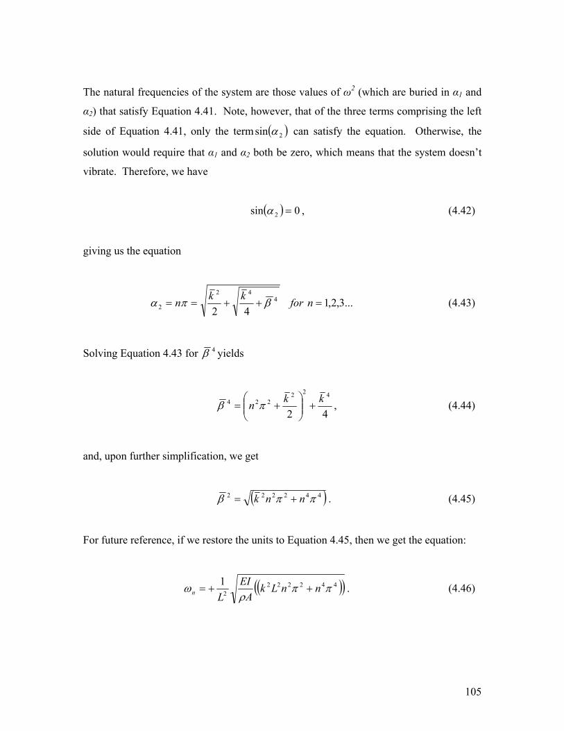
The natural frequencies of the system are those values of ω2 (which are buried in α1 and
α2) that satisfy Equation 4.41. Note, however, that of the three terms comprising the left
side of Equation 4.41, only the term ( )2sin α can satisfy the equation. Otherwise, the
solution would require that α1 and α2 both be zero, which means that the system doesn’t
vibrate. Therefore, we have
( ) 0sin 2 =α , (4.42)
giving us the equation
...3,2,142
442
2 =++== nforkkn βπα (4.43)
Solving Equation 4.43 for 4β yields
42
422224 kkn +
+= πβ , (4.44)
and, upon further simplification, we get
( )442222 ππβ nnk += . (4.45)
For future reference, if we restore the units to Equation 4.45, then we get the equation:
( )( )4422222
1 ππρ
ω nnLkA
EILn ++= . (4.46)

106
Equation 4.45 now gives us an analytical means to understand the behavior of the natural
frequencies of the system as the magnitude of the wave (or tensile) term 2k is increased.
Since we are most interested in tensile loads, we will increase the magnitude of the 2k term. Figure 4.10 visually depicts the behavior of the natural frequencies as the
magnitude of the wave term, or tensile load, is increased.
Figure 4.10. As the magnitude of the wave term 222 Lkk = is increased, the
corresponding roots of the characteristic equation also increase.
The next chapter will show experimental validation of the above analysis, and verify the
use of beam under uniform tension equation, Equation 4.27.
4.6 Chapter Summary
This chapter presents a historical summary of the work performed in the area of thin plate
and membrane dynamic equation development. Although it is not a new contribution to
the scientific community, it serves its purpose as a detailed summary distinguishing the
nomenclature and nuances separating thin plates and membranes. All too often,

107
structural elements that are thin plates are incorrectly referred to as membranes and vice
versa.
The materials under consideration for membrane mirrors are, in fact, membranes. They
are subject to the limitations of membrane dynamics, and proper modeling of membrane
optics must take into account such limitations. However, augmenting Kapton or Upilex
with active material, like PZT, motivates us to consider a small but non-negligible
amount of bending rigidity in our model. Consequently, we have augmented the
transverse vibration equation of a beam with a wave (or string) term to capture both types
of dynamics. This augmentation is important, as it now allows us to incorporate the more
complex interaction between a piezoelectric bimorph or unimorph and a membrane
sample. Such interaction cannot be modeled with pure membrane theory.
In summary, membranes differ from thin plates in that they: 1) cannot resist a bending
load, due to their lack of flexural rigidity, and 2) can only sustain tensile loads, which
consequently can lead to wrinkles. Keeping these differences in mind, we can now
explore other aspects of membrane mirror design criteria in subsequent chapters. The
next chapter will show experimental validation of the use of beam under uniform tension
equation.


![arXiv:1202.1831v1 [cond-mat.mtrl-sci] 7 Feb 2012The so-called Modern Theory of Polarization, which rigorously defines the spontaneous polarization of a periodic solid and provides](https://static.fdocuments.net/doc/165x107/5f0868467e708231d421dbba/arxiv12021831v1-cond-matmtrl-sci-7-feb-2012-the-so-called-modern-theory-of.jpg)


![AN INTRODUCTION TO OPERAD THEORY - Alistair Savage · 2018. 8. 17. · of meta-algebraic structure. Operads were rst rigorously de ned by J. Peter May in his 1972 book [May72], which](https://static.fdocuments.net/doc/165x107/5fc0f60adf6d8312e44237ff/an-introduction-to-operad-theory-alistair-savage-2018-8-17-of-meta-algebraic.jpg)