Chapter 3D (Sedimentation)
18
Water Treatment: Sedimentation 1
-
Upload
syamim-bakri -
Category
Documents
-
view
35 -
download
4
description
share
Transcript of Chapter 3D (Sedimentation)
Water Treatment: Sedimentation
1

Sedimentation/Settling
• Following flocculation, the water then flows
into the settling basins
• Water is nearly quiescent – low flow with
little turbulence little turbulence
• Water resides for at least 3 hours and the
flocs settle out and collect at the bottom.
2

Settling in Treatment Train
3

Circular Clarifiers
4

Type I Settling -- Stokes’ Law
µ
ρρ
18
)( −= s
s
gv
where
ν = settling velocityνs = settling velocity
ρs = density of particle (kg/m3)
ρ = density of fluid (kg/m3)
g = gravitational constant (m/s2)
d = particle diameter (m)
µ = dynamic viscosity (Pa�s)5
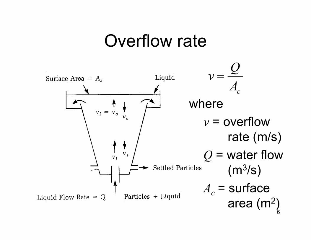
Overflow rate
cA
Qv =
where
v = overflow v = overflow
rate (m/s)
Q = water flow
(m3/s)
Ac = surface
area (m2)6

Types of Particle Settling
• Type I settling applies to particles that settle with constant velocity -- particles will be removed if v > vs
• If particles flocculate during settling, • If particles flocculate during settling, velocity generally increases – Type II settling
• As particle concentration increases with depth, zone settling occurs
• At bottom of tank compression settling occurs
7

SedimentationIdeal sedimentation basins (Type 1) - REGTANGULAR BASINParticle removal is dependent on the
overflow rate, v0
In order for particle to be removed settling
velocity , vs must be sufficient so that it
reaches the bottom during the time the
8
water resides in the tank (td).
If Vs = Vo , then
vs > v0 , 100 % particles should be easily removed
vs = v0 , 100 % particles removed
vs < v0 , some fraction of the particles will be removed P =
100 vsv0
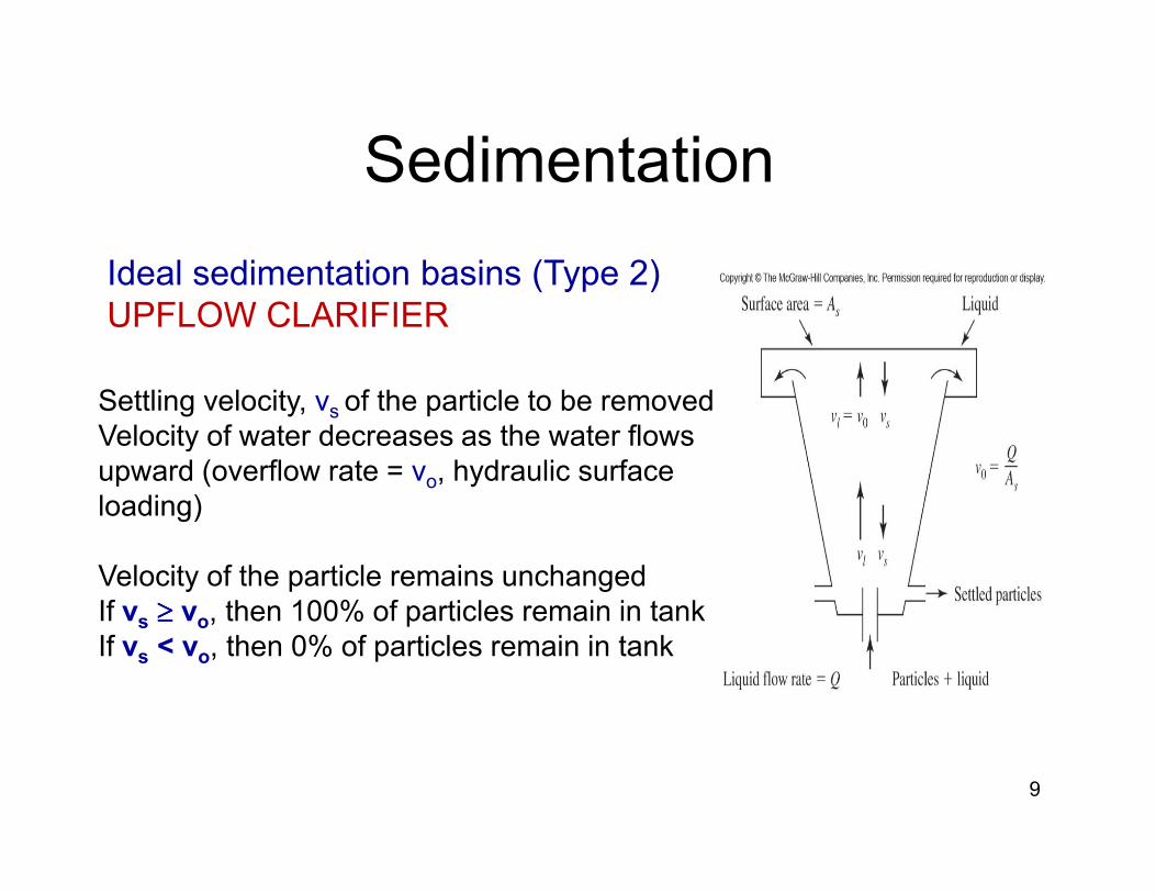
Ideal sedimentation basins (Type 2)
UPFLOW CLARIFIER
Settling velocity, vs of the particle to be removed
Velocity of water decreases as the water flows
Sedimentation
9
Velocity of water decreases as the water flows
upward (overflow rate = vo, hydraulic surface
loading)
Velocity of the particle remains unchanged
If vs ≥≥≥≥ vo, then 100% of particles remain in tank
If vs < vo, then 0% of particles remain in tank
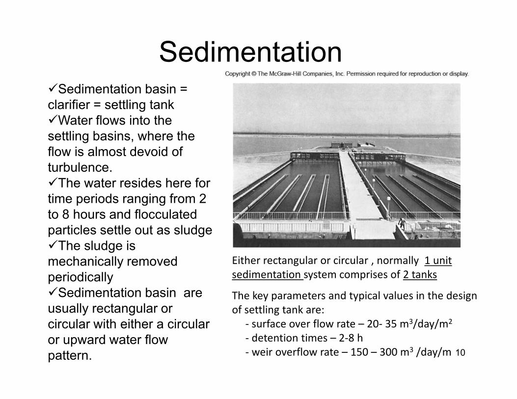
�Sedimentation basin =
clarifier = settling tank
�Water flows into the
settling basins, where the
flow is almost devoid of
turbulence.
�The water resides here for
time periods ranging from 2
Sedimentation
10
time periods ranging from 2
to 8 hours and flocculated
particles settle out as sludge
�The sludge is
mechanically removed
periodically
�Sedimentation basin are
usually rectangular or
circular with either a circular
or upward water flow
pattern.
The key parameters and typical values in the design
of settling tank are:
- surface over flow rate – 20- 35 m3/day/m2
- detention times – 2-8 h
- weir overflow rate – 150 – 300 m3 /day/m
Either rectangular or circular , normally 1 unit
sedimentation system comprises of 2 tanks

Sedimentation
The sedimentation tank be
divided into four zones: inlet,
settling, outlet and sludge
storage
Inlet zone - to evenly distribute
the flow and suspended particles
across the section of the settling
zone*
Sludge storage zone- depends
*
11
Sludge storage zone- depends
upon the method of cleaning, the
frequency of cleaning and the
quantity of sludge estimated to be
produced.
Outlet zone- to remove the
settled water from the basin with
out carrying away any of the floc
particlesZones of sedimentation: (a) horizontal flow clarifier , (b)
upflow clarifier
*

*Sedimentation
12
*

Example
Calculate the diameter and depth of a circular
clarifier for a design flow of 3800 m3/d and an
overflow rate of 0.00024 m/s and a detention
Sedimentation
13
overflow rate of 0.00024 m/s and a detention
time of 3 h. Calculate the weir loading rate by
assuming the total effluent weir is 20 m.

Solution
Calculate the diameter and depth of a circular clarifier for a design flow of 3800 m3/d and an
overflow rate of 0.00024 m/s and a detention time of 3 h. Calculate the weir loading rate by
assuming the total effluent weir is 20 m.
Solution
Volume , V = Q/t
= (3800 m3/d)/ ( 3/24)d
= 475 m3
Q = 3800 m3/d = 0.044 m3/s
Sedimentation
14
Surface overflow rate = Q/A
0.00024 m/s = 0.044 m3/s
A m2
Area, A = 183.3 m2
Volume, V = AD
D =V/A
= 475 m3/183.3 m2
= 2.59 m
Diameter = 15.3 m
Weir loading rate = Q/ Lw
= 3800 m3/d
20 m
= 190 m3/day.m ( OK!)
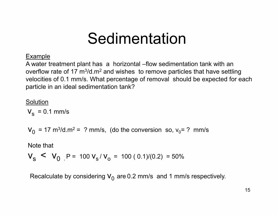
Example
A water treatment plant has a horizontal –flow sedimentation tank with an
overflow rate of 17 m3/d.m2 and wishes to remove particles that have settling
velocities of 0.1 mm/s. What percentage of removal should be expected for each
particle in an ideal sedimentation tank?
Solution
v
Sedimentation
15
vs = 0.1 mm/s
v0 = 17 m3/d.m2 = ? mm/s, (do the conversion so, v0= ? mm/s
Note that
vs < v0 , P = 100 vs / vo = 100 ( 0.1)/(0.2) = 50%
Recalculate by considering v0 are 0.2 mm/s and 1 mm/s respectively.

SEDIMENTATIONExample
Determine the surface area of a sedimentation tank . The design
flow is 0.044 m3 /s. Use a design overflow rate of 20 m / day.
Find the depth of the sedimentation for the given overflow rate
and detention time.
Solution:
1) Find the surface area.
First change the flow rate to compatible units.
(0.044 m3/ s)(86,400 s / day) = 3801.6 m3 /day
The surface area is = 3801.6 m3 /day
Tank 1 Tank 2
Flocculation tank
16
The surface area is = 3801.6 m3 /day
20 m/ day
=190.m2
2) Find the length to width dimension
Common length-to-width , L: W ratios ( 2:1 < L:W < 5:1 , and
lengths seldom exceed 100 m. A minimum of two tanks is always
provided.
use two tanks, each with a width of 5 m, a total surface area of
190 m2 ,
Length = 190 m2 /(2 tanks)(5 m wide) = 19 m
meet our length-to-width ratio of 3.8 : 1 ( OK!)
Flocculation tank
Se
dim
en
tation
tan
k
Se
dim
en
tation
tan
k
Tank 1
L= 19m,
W = 5 m
Tank 2
L= 19m,
W = 5 m
Q = 3801.6 m3 /day

3) Find the tank depth.
Rule of thumb that the detention time should be 2-8 h.
Assumed the detention time of 120 min
Q = V/t
V = Q t
Sedimentation
17
V = Q t
V = (1900.8 m3)(120 min)( d ) = 158 m3
d 1440 min
Depth= 158 m3 =1.684 m,= 1.7 m
95 m2
The final design would then be two tanks, each having the following
dimensions:
5 m wide x 19 m long x 1.7 m deep plus sludge storage depth.

END
18