
Chapter 3 The Square Monopole Antenna -...
30
Chapter 3 The Square Monopole Antenna Monopole antennas are used in communication systems at a wide range of frequencies. Electrical properties of these antennas are dependent upon the geometry of both the monopole element and the ground plane. The monopole element is either electrically short with length much less than a quarter-wavelength or near-resonant with length approximately a quarter-wavelength. This clement can be thin with length-to-radius ratio much greater than 10 4 or thick with length-to-radius ratio of 10 1 - 10 1 . In addition. the ground-plane dimensions may vary from a fraction of a wavelength to many wavelengths [\Veilwr, Traditionally, a monopole geometry consists of a vertical cylindrical element at the center of a perfectly conducting, infinitely thin. circular ground plane in free space. Electrical characteristics of such antennas are primarily a function of only three parameters: the element length, clement radius, and the ground-plane radius, when each is normalized to the excitation wavelength. Radiation pattern of such antpunas are uniform in the azimuthal direction. U\VB monopole antennas fall in to volumetric and non- vol umetric categories based on their structures. )JOll volumetric U\VB antennas are lllicrostrip pla- nar structures evolved from the volumetric structares. ,vith different matching techniques to improve the bandwidth ratio without loss of the radiation pattern properties. 33
Transcript of Chapter 3 The Square Monopole Antenna -...
Chapter 3
The Square Monopole Antenna
Monopole antennas are used in communication systems at a wide range of
frequencies. Electrical properties of these antennas are dependent upon the
geometry of both the monopole element and the ground plane. The monopole
element is either electrically short with length much less than a quarter-wavelength
or near-resonant with length approximately a quarter-wavelength. This clement
can be thin with length-to-radius ratio much greater than 104 or thick with
length-to-radius ratio of 101 - 101 . In addition. the ground-plane dimensions
may vary from a fraction of a wavelength to many wavelengths [\Veilwr, 20O::~1.
Traditionally, a monopole geometry consists of a vertical cylindrical element at
the center of a perfectly conducting, infinitely thin. circular ground plane in free
space. Electrical characteristics of such antennas are primarily a function of
only three parameters: the element length, clement radius, and the ground-plane
radius, when each is normalized to the excitation wavelength. Radiation pattern
of such antpunas are uniform in the azimuthal direction.
U\VB monopole antennas fall in to volumetric and non- vol umetric categories
based on their structures. )JOll volumetric U\VB antennas are lllicrostrip pla
nar structures evolved from the volumetric structares. ,vith different matching
techniques to improve the bandwidth ratio without loss of the radiation pattern
properties.
33
34 CHAPTER 3. THE SQUARE MONOPOLE ANTEN'IVA
3.1 Volumetric UWB Antennas
Volumetric U\VB antennas date from the days of spark gap systems. In 1898.
Oliver Lodge disclosed spherical dipoles, square plate dipoles, bi--conical dipoles
and bow -tie dipoles [Lodge, 1898] and int.roduced the concept of a monopole
antenna with earth as the ground. A renewed interest in the wide band antennas
led to the rediscovery of biconical and conical monopoles by Carter in 1939
[CarteL 1939aJ. Carter improved upon Lodge's original design by incorporating a
broadband transition between a feed line and radiating elements [Cartf'l', 1!)39bJ.
The complete analysis of these antenna.s can be found in [StutZllIHU, H.d.J.
Another remarkable invention is the classic "volcano smoke antenna developed
by Kraus in 1945, a deta.iled report of which can be found in [Lp\:, Palllsell,
2003]. This antenna topology offers exceptional bandwidth and azimuthal omni
directiollali ty.
Sleeve monopole configurations [StutZlllCill. luLJ excited using a coaxial
transmission line exhibit broad band radia.tion behavior. The sleeve exterior acts
as a radiating clement while its interior a.ct.s as the outer conductor of the feed
coaxial transmission line.
Stohr proposed t.he use of ellipsoidal monopoles and dipoles [Stohr, 1968J
which was re -discovered in [:.: ara~'all Prasad AgarwalL 199~]. This paper presents
t he extensive analysis carried out on square, rectangular and hexagonal disc
mOllopole antennas in addition to the elliptical design.
Square/ rect.angular monopole antennas are inherently bandwidth limited
and in order to improve the bandwidt.h, various techniques were proposed. In
[Lee E., 1999J. it was demonstrated t.hat. when a shorting pin is added to a planar
monopole antenna, an additional mode is excited belo,,, the fundamental mode.
By optimizing the dimensions 50% size reduction is obtained when compared to
an equivalent planar monopole without a shorting pin. In [Anoh P. V., 20(H].
two techniques are presented; offset feeding and the use of orthogonal square
monopoles on a. circular base to obtain wi(k band response and omnidirectional
radiation.
The use of beveling technique [AlllllH-lllll. 2001] and that of a shorting pin
[Anllll<lllll. 2003] can improve the overall impedance bandwidth of square monople
antennas. In [AntoIlillo-DClviu E.. 200:5J the use of double feeding and in [Kin-
3.1. VOLUAfETRIC U\VB ANTEi\lNAS 35
Lu \Vong. 200Sbj, 3 t.rident shaped feeding is proposed to improve the impedance
bandwidth of such antennas.
Effect of finite ground plane on the impedance band\vidth of planar monopole
antenna was studied in [Saou-\Ycll Su, 200-1]. Their study shows that the first
resonance is greatly affected by t.he ground plane and t hat there exists an optimal
diameter of the circular ground plane for achieving a maximum impedance
bandwidth. Large ground-plane effects on the radiation pattern and antenna
gain are also st.udied in this paper. especiall~' for t.he lmver frequencies in the
antennas impedance handwidth.
In [Kin-Lu Wong, 200,1b], a metal-plate monopole of inverted-L shape with
a ma.tching tuning portion is mounted at t.h(~ top edge of the supporting metal
frame to create an ant.enna with ultra wide bandwidth. Impedance bandwidth
of this antenna is from 1.89-10.14 GHz. A modified version of this antenna is
proposed in [Kin-Lu \Vong, 200-1aj. with bandwidth from 1.890·- 6.450 GHz t.o
integrate with laptops a.s it covers the U~ITS (1.920 - 2.170 GHz) and \VLAN
(5.150-5.350/ 5.725-5.875 GHz) bands.
To improve the impedance bandwidth. wide slots are embedded in the rectan
gular monopole in [Valdera~ D., 2005]. The slots created additional I'e~onances
and the a.chieved bandwidth rat.io is 1 : 3.75.
In [Saou-'Ven Su, 2005a], a . U' shaped slot is incorporated to a square planar
antenna wit.h beveling to reali~e band Hotch to forbid interference with the IEEE
802.11a and HIPERLA~/2 systems. An annular slot inside the same monopole
effectively notched out the 5.15-5.35 and 5.15 5.825 GHz bands with a VS\VR
> 14 as demonst.rated in [.JinIlllling (lilt, 200G]. In [Kin-Lll \Yong, 200ficl] an arc
shaped slot is incorporated in to a circular disc monopolc autenna to achieve the
band notch. The length of the arc controls the frequency that is being not.ched.
To design a rectangular monopole antenna with improved bandwidth, a 'U'
shaped metal plate lllonopole in implement.ed in [Saou-\VPll Su, 200Gb].
In [XUClll Hili \Vu, 200fi] , t.he charact.eristics of four planar dipoles are studied.
Pulses radiated in different directions arc presented in this paper for bot h single
band and multi-band schemes in U\VB applications.
In [CIWll. 2005] the design of broad band hi-arm rolled IIlollopole antenna.
constructed by wrapping a planar monopole is present.ed and its transfer response
have been analyzed.
36 CHAPTER 3. THE SQUARE JIONOPOLE ANTEI'n\lA
The coupled sectorial loop antenna in [1\ a.cler Bchdad, 2005] achieves ultra
wide bandwidt.h t.hrough a magnetic coupling of two adjacent sectorial loops. The
antenna exhibits 8.5:1 frequency range with a VS\VR lower than 2.2. Dimension
of this antenna is smalk>r than 0.37 Ao at the lowest frequency of operation and
has consistent radiation pattern throughout the band.
The monopole in [Ka-Lcllug Lau, 2005] is formed by connecting four trape
widal plates orthogonally. A circular patch which is short.ed to the circular
ground plane by four shorting wires is placed at the top of the Illonopole. The
antenna posses 10 dB bandwidth of 138 9C which is about 49 times that of the
corresponding monopole wire-patch antenna.
In [Vald(~rns D., 2006] a design process for improving the bandwidth of beveled
planar monopole antennas has been proposed by studying movements over the
Smit.h chart. The involved Illonopole variables WE're the height. the width. the
bevel angle of the lower edge. t.he feeding length, and the capacitance \vith the
ground plane. These parameters are conveniently combined t.o implement. a u\\rB
antenna with a frequency-independent bandwidth greater than 1 : 37 for VS\VR
< 2. The radiation patterns are nearly constant and omnidirectional at the
represent ativc frecllwncies.
The antenna optimization proposed in [I\ikoJay Tdzhell:-iky. 2006] makes use
of t.he genetic algorit.hm and is based on the time domain characteristics of the
antenna. Optimization procedure presented in t.his paper aims at finding an
antenna with low VS\VR a.nd low-dispersion to ensure high correlation bet'\veen
the time-domain transmitting antenna input signal and the receiving antenna
output signal. This procedure has been applied to a simplified version of the
volcano smoke antenna proposed by Kraus. and can be extended to any other
type of U\VB antenna.
In [Georg(' TholllCls K .. 2006J. the authors proposed a new ultra wide band,
sleeved transmission line-fed rectangular planar disc IIlonopole antenna with a
small ground plane. Objective of the authors was t.o design a. monopolE' antenna
with improved radiation performance than existing ones. The antenna offers an
ultra broadhand performance in the frequency band 0.5 9.0 GHz with a VS\VR
of less than 2.5 : 1.
Certain U\i\'B applications such as a win~less dongle require antennas ('on
stricted in space and an ant.enna design suit able for such applications were
3.2. NON- VOLUMETRIC U\VB ANTE.NNAS 37
proposed in [Saou-\Veu Su, 2007]. This compact ant.enna comprises a L-shaped
rectangular monopole element and a matching section and is relatively easy t.o
fabricate. In [Jae\voong Shin. 2007] yet another design can be found suitable
for UWB dongle applications. In [Sa.oll- \Ven (St.ephell) Sl1. 2007] the antenna
is mounted at the top portion of the PCB and one end of the radiating arm is
short-circuited to the system ground plane. \Vith the proposed antenna st.ructure,
wide operating band,vidth of larger than 7.6 GHz is obtained that easily cover
the 3.1-10.6 GHz band.
In [In'IW Ang. 2007] design of a double layer. probe- proximity coupled. stacked
diamond-shaped microstrip patch antenna is proposed with ultra wide bandwidth.
The authors have shown that broad band characteristic can be achieved by exciting
all the higher order modes in the microstrip patch antenna simultaneously by
shorting the ringing tail through simple capacit.or coupling. The proposed antenna
has an impedance bandwidth of 101.8 % for VS\VR < 2.
A compact wide band folded-shorted antenna is presented in [Giuseppe Ruvio,
2007] that employs different impedance bandwidth enhancing techniques together
to cover the U\VB spectrum. The microstrip feed of the antenna is printed on FR4
and a folded t.hin metallic sheet is connected to the printed element and shorted
across the full length of the ground plane. This grounding significantly enhances
the impedance bandwidth and helps to mitigate the effect of the asymmet.ry due
to the offset feed arrangement
An omnidirectional mono pole antenna shaped by symnwtTically wrapping a
PEC sheet that. has two trapezoidal cut.s at the bottom corners is proposed in
[Xuan Hili \VIl. 200~1. It has an extremely wide impedance bandwidth of 132
% while keeping an omnidirectional and wide band radiation over the 3.1-10.6
GHz band. Finite ground plane of this antenna int.roduces ripples in the gain
versus frequency response which can be estimated by a simple expression with
the knowledge of ground plane size. Furthermore. the ripples can be removed by
resistively loading the edge of the ground plane.
3.2 Non-Volumetric UWB Antennas
As already mentioned, non-volumetric U\VI3 antennas are microstrip planar
structures evolved form the volumetric strnctures. In [Sdwntz H. G., 2001],
38 CHAPTER 3. THE SQUARE I\10NOPOLE A1'v'TENNA
the diamond and in [Lu G., 2003], the rounded diamond antennas have been
shown to have wide-band properties suitable for ultra wide band applications.
In [Gllofeng Lu, 2004]' theoretical analysis. simulation::; and experiments are
all conducted to further characterize these two antennas in terms of radiation
pattern. gain versus frequency and impedance properties.
U\VB on-body propagation channel measurements \vere performed in [Alo
mainy A., 2005J to study the deterministic channel characteristics. A printed
horn shaped self- complementary antenna and a planar inverted cone antenna
were investigated for their effects on the channel behavior. Results show that the
hybrid use of different types of UWB antennas can effectively improve channel
behavior in body-centric wireless networks.
In [Low Z. :\.,2005]. a monopole a.ntenna is proposed where the authors used
three techniques to realize compactness and wide bandwidth: dual slots on the
rectangular patch. a tapered connection between the rectangular patch and the
feed line and a partial ground plane flushed with feed line. This antenna shows
stable characteristics over the f'ntire U\VB frequency band.
The correspondence [Clwn Ying, 2005] presented a planar antenna in low
temperature co- fired ceramic technology for a single -package solution of U\VB
radio. The antenna has an elliptical radiator fed through a microstrip line. The
radiator and the microstrip line share the same ground plane with the other U\VB
radio circuitry. The prototype antenna has achieved bandwidth of '" 110% from
3 10.6 GHz with broad patterns, and relatively constant group delay.
The printed circular disc monopole antenna fed by microstrip line is investi
gated [.Tiallxill Liallg, 2005j. Impedance band width of this antenna is from 2.78
- 9.78 GHz and the first resonanc'c has becn well account.ed numerically. The
antenna has been cha.racterized in the frequency and time domains.
In [.Tocri It Vf'fhif'sL 200S], a new antenna topology is pn~sented bascd on
the' printed tapered monopole antenna.. A slot is added in the tapered radiating
clement. and in t he ground plane, t.o yield wide band b~~havior and good matching.
The matching performance and the pulse distortion of t.he antenna in th(~ presence
of human tissue are also studied.
In [Y1l-.Jill11 RPlI, 20()(j]. an annular ring is electromagneticall~' coupled to
nmlize U\VB. Ground plane of the microstrip line is removed beneath the annular
ring and the -10 dB impedance bandwidth of the antenna. is from 2.8 to 12.3
3.2. NON-VOLUMETRIC U\VB ANTENNAS 39
GHz. Radiation patterns are stable within the operating bandwidth with an
average antenna efficiency of 81 %.
In [Yildirilll. 200G], a. microstip fed, small, low profile, branched monopole
antenna is presented with ultra wide bandwidth. By adjusting the branch length
and/or adding another brauch, the design can be adapted for \VLAN, BIuetooth
and UWB applications. However, asymmetry in the geometry of the antenna has
affected the radiation pattern, which is slight.ly modified from omnidirectional.
A double-sided rounded bow-tie antenna with ultra wide bandwidth is propm;ed
in [Tu t ku Karacoi<lk, 2006]. The authors have shown that ant.ennas with rounded
patches provide wider bandwidth with higher co-polarization and lower cross
polarizat.ion levels for the U\VB range compared t.o their fiat-end counterpart.s.
In [Shi-Wpi QIl. 200Gj an ultra wide band a monopole antenna wit.h rounded
corners is proposed. By introducing a coplanar waveguide resonant cell. the
proposed antenna could notch the \VLAX bands for a VS\VR > 10. This compact
antenna operates from 2.67 to over 12 GHz. and shows omnidirectional radiation
pattern.
The proposed antenna design in [Pe.Vl'ot-Solis ~1. A., 20()(j] uses the beveling
technique for both t.he radiator and the ground plane so as t.o provide necessary
feed gap betwE'en them to achieve widp impedance bandwidt h.
In [Young .lUll Cho, 2006]. a staircase shapE' is incorporated in the ll1onopole
element and t.he ground plane is redesigned to realize a U\VB antenna wit h a
compact configuration of 25x26 mm2. l\Ieasured bandwidt.h of the antenna is
from 2.9-14.5 GHz and a detailed chara.cterization in t.he frequency and time
domains have been presented.
In [),Iichit.Hka AUH'ya, 200G]. design of planar broadband antellnas consisting of
self-complementary radiating elements and a tapnred microstrip line is proposed.
Deta.iled FDTD analysis of thes(~ antennas are also prescnted in this paper.
In [Knr'<lllloto, 200(j]. design of a planar radiator that does not require a large
ground is presented. The design consists of large and small ellipt.i('al elcments in
parallel arrangemcnt. To reduce mutua.l coupling between t.hese elements and to
improve impedallcc bandwidth, an elliptica.l slot is designed in the large elliptical
element.
In [ShUIl-YlIll LiB. 200G], a pentagon ~haped monopole is proposed with ultra
wide bandwidth. By embedding a.n inverted V-shaped slot along the boundary of
40 CHAPTER 3. THE SQUARE MONOPOLE ANTENNA
this antenna, controllable notch has been demonstrated.
Design of textile antennas for U\VB wireless body area network (\\lBAK)
applications is presented in [:"Ia.ciej Klcml1l, 2006]. The proposed coplanar
waveguide fed printed monopole and U\VB annular slot antennas offer direct
integration into clothing due to Cl very small thickness (0.5 mm) and flexibility.
The antennas cover the 3.1--10.6 band and the transfer functions are comparable
to the PCB reali2ation. The authors have successfully transmitted very short
pulses using textile antennas.
Design of the printed-circuit antenna in [Rambabu K., 200G] uses a stepped
patch in combination with multiple resonating elements to realize a bandwidth
of more than 150%. The authors have performed a phase center analysis which
shows very small variations over the entire available bandwidth.
In [Sadlill Gnpta, 2006]. microstrip and CP\V bfh'"ied configurations of planar
invert.ed conical antennas are presented and compared for U\VB systems. Design
of these antellnas follo,vs a third order polynomial equation and hence can be
designed easily.
A variation of the defected microstrip structure technique is employed to
enlarge the baIHhvidth of a planar ultra wide-band monopole in [Pe~T()t-S()lis
t\l. A., 2007]. By introducing a defect in the mierostrip feed line, the lov·:er
bandwidth limit is lowered without affecting the antenna gain and radiation
pattern. The bevel technique in the ground plane near to the feeding point is used
to increase the highest bandwidth limit. The 50 x 50 mm2 planar oIIlnidirectional
antenna has a voltage standing wave ratio 2 from 2.1 to 12.3 GHz.
In [;\ts(}lHjcrh C. A ZE'lllli , 2007], a compact crescent.-shape microstrip antenna
is proposed, evolved from the elliptical patch antenna by carving a circular hole
inside symmetrically. The circular aperture introduces an additional antenna
in-band resonance and provides wider bandwidth with more design flexibility.
Radiation properties of this antenna is similar to the full elliptical antenna, with
409(', reduction in area (GO(X of the ellipse area). The characteristic current modes
on the crescent antenna are identified and design equation are derived for the
lowest frequency of operation of this antenna_
In [Fram'is Jacoh K., 2007]. different branches arc top loaded on a planar strip
mOllopole and dimensions of the branches are optimized for U\VB performance.
The antenna shows 10 dB return loss from 3.1 - 9.6 G H~ and Illonopole- like
3.2. NON- VOLUl\,IETRIC Un'B A1\lTENT
NAS 41
radiation. The proposed antenna of dimension 65x35 'fnm2 can fit into the present
day mobile hand sets of typical dimension 100 x 45 mm2 .
The broadband mirrostrip-fed printed antenna proposed in [Eldek, 2007]
for phased antenna array systems consists of two parallel-modified dipoles of
different lengths. Tlw regular dipole shape is modified to a quasi-rhombus shape
by adding two triangular patches. A modified array configuration is proposed
to further enhance the antenna radiation characteristics and usable bandwidth.
The proposed antenna provides end fire radiation patterns ,vith high gain. high
front-to-back ratio, low cross-polarization level, wide beam width. and wide
scanning angles in a wide bandwidth of 103 %.
In [.Jin-Ping Zhang, 2007]. a microstrip fed semi-elliptical dipole antenna is
proposed and designed to cover the 3.1 10.6 GHz UvVB. Radiation patterns are
similar to those of a conventional dipole antenna with dimension only about one
third of the wavelength instead of half wavelength at the lower frequency. \Vith
simple and proper modification of the patches, a. frequency-notched antenna is
also designed.
In [Zhi King Chen, 2007]' a small printed antenna is described with n~duced
ground-plane effect. The radiator a.nd ground plane of the antenna arc etched
on a printed circuit board \""ith an overall size of 25 x 25 mm2 . A notch is cut
from the radiator and a strip is asymmetrically attached to the radiator. The
antenna achieves a broad operating bandwidth of 2.9-11.6 GHz for a lO-dB
return loss. Effect of the ground-plane on the impedance bandwidth is greatly
reduced by the notch in the radiator because the electric currents on the ground
plane are significantly suppressed at the lower edge operating frequencies. The
antenna features three-dimensional omni-directional radiation wit.h high radiation
efficiency of 79-95o/c across t.he U\VB band,vidth.
In [Yi-'\lin Lu, 2007]' ultra wide band antenna is designed using a double
printed circular disc. Reasonable theoretical analysis of the antenna has been
carried out in this paper.
A simple design of a printed circul~tr monopole antenna with band-not.ch
characteristic is presented in [Chih- Yu Huaug. 2007]. Frequency notch in this
antenna is created by cntting a pie-shaped slot on the circular radiating patch.
A parametric study of t.he printed elliptical monopole antennas is presented in
[Anoh P. V .. 2001]. Based on this, design equations are derived for these antennas
42 CHAPTER 3. THE SQUARE MONOPOLE ANTE1VNA
which are validat(~d by measurements.
A planar shorted dipole antenna capable of generating a 9:1 bandwidth (820-
7340 :\JHz) is presented in [\Vei-Yu Li, 2007J. The radiating element consists
of two C- shaped radiating arms occupying a compact area of 0.30A x 0.47 A,
where A is the wavelength of the desired lower edge of the band of operation. In
addition to the use of C-shaped radiating arms, which reduces the total length
of the proposed antenna when compared to the case of using straight radiating
arms, the short circuiting of the two radiating arms further effectively decreases
t he lower frequency with a fixed antenna size.
In [Thyh-Ghu8.ng :\la, 2007], to achieve band-rejection at the \VLAN bands,
strips of t.he fork shaped monopole are folded back to result. in a pair of coupled
lines on the radiator. Based on the band-notched resonance, an equivalent
circuit model is proposed for the antenna and the calculated antenna input
admittance has been shown to agrees with the full-wave simulation dat.a. Using the
normalized antenna transfer function, the radiation characteristics are investigated
thoroughly. Th(~ transmission responses of a transceiving antenna system and
their corresponding transient analysis are also discussed in this paper.
The lov.·'cr edge curve of a monopolc antenna is a.n important parameter in
determining the impedance bandwidth. In [Chillg \\'('i Ling, 2007], a new edge
curve chara.cterized by the binomial function is proposed. The effect on the
impedance bandwidth with different order of the binomial function and the gap
between the antenna and ground plane has been investigated in this paper.
Impacts of the 3.1-10.6 GHz on-human-body UWB channel on the impulse
radio wireless body area network system has been studied in [Yu(=' Ping Zhang,
2007]. A performancf~ evaluation method is presented in this paper for the realistic
U\VB-\VBAN systems. which observes the waveform distort.ion along the signal
path. Measurement. and characterization of the 3.1-10.6 GHz on-human-body
U\VB channel are devised to generate the radiographs of path loss and delay
spread for the first time in this paper. The study shows that the human body
effect is more significant than environment effect when thf' propagation channel
contains no line-of-sight path. Various candidate pulse shapes and modulat.ion
schemes for U\VB \VBA:\ are studied and their performances \vith t he measured
vVBA:\ chamwl arc evaluated and compared.
In [Ching-Hsing Lno, 2007], Cl dual band-notched CP\V fed monopole antenna
3.2. NON-VOLUMETRIC U\VB ANTENNAS 43
is proposed where a ring in the feeding structure is used to incn~ase the impedance
bandwidth. Two quarter-wavelength tuning stubs inserted into the feeding ring
and radiating ring: respectively, creates two band-notches at 5.15 and 5.75 GHz
across the U\VI3 from 2.6 - 12 GHz. The novel design is quiet compact and
suitable for creating U\VB antenna with dual narrO\v frequency notches.
In [Keyvan Bahadori, 2007], an elliptic-card ultra wide band planar antenna is
proposed. The design consists of an elliptic radiating element and a rectangular
ground plane. The feeding mechanism comprises of a microstrip line on the ot her
side of the substrate and connecting the line to the elliptic element by a via. The
structure of t h8 ant8Ima is miniaturized by optimizing its elliptic profile and the
required ground plane size is only 22x 40 m.m2. Housing effects on the antenna
performance arc also studied in this paper.
In [Vi Diug: 2007], a very compact elliptical monopole antenna with a size of
35x20 mm2 is designed with ultra wide bandwidth. \\ride impedance match is by
two matching slits at the lower section of the elliptical patch. In addition. using
a slot and embedded resonant cell, the authors have demonstrated band notch at
5.5 GHz.
The CP\V fed band-notched antenna proposed in [Sang-Ho Lee, :2007] uses
tilt steps of two different sizes for improving band width and two folded strip
lines for band notch.
The antenna proposed in [Chong Yu Hong: 2007] consists of Cl radiation patch
that has an arc-shaped edge and a part.ially modified ground plane. The ground
design comprises of two bevel slots on the upper edge and two semicircle slots at
the bottom edge of the gronnd plane to improve the input impedance bandwidth
and the high frequency radiation performance. By embedding a pair of T -shaped
stubs inside an elliptical slot ('ut in the radiation patch, a notch at 5.5 GHz is
obtained.
In [Reza Zaker. 2()()~]. a novel modified microstrip-fed ultra wide-band planar
monopole antenna with variable frequene:y band-notch characteristic is presented.
By inserting two slots in the ground plane on both sides of the microstrip feed
line, wide impedance bandwidth is produced. A modified H-shaped conductor
backed plane with variable dimensions is uSt~d in order to generate the frequency
band-stop performance and control band-notch frequency and bandwidth. The
designed antenna has a small size of 22x22 rnm 2 and operates over the frequency
44 CHAPTER 3. THE SQUARE i\IO}'lOPOLE ANTENNA
band between 3.1 and 14 GHz for VS\VR < 2 while showing tlw band rejection
performance in the 5.1 to 5.9 GHz ff(~quency band.
The antenna design proposed in this chapter is a planar square monopole with
redesigned ground plane to opera.te in the ultra wide band. As already mentioned,
typical design practice to achieve U\VB with a square/ rectangular patch is by
beveling, parasitic strips or by employing multiple feeding, which may add t.o
the design complexity. The proposed design is novel by introducing Cllts in the
ground plane that. follow specific design guidelincs. From a parametric study,
design equations arc obtained to facilitate designing the antenna on laminates
of any permittivity. A band notch scheme is also proposed to limit. radiation
in the \VLA="J band. Studies conducted on the frequency domain radiation
characteristics of the prototype a.nt.enna is also present.ed in this chapter.
3.3 Antenna Geometry, Design and Optimization
3.3.1 Geometry
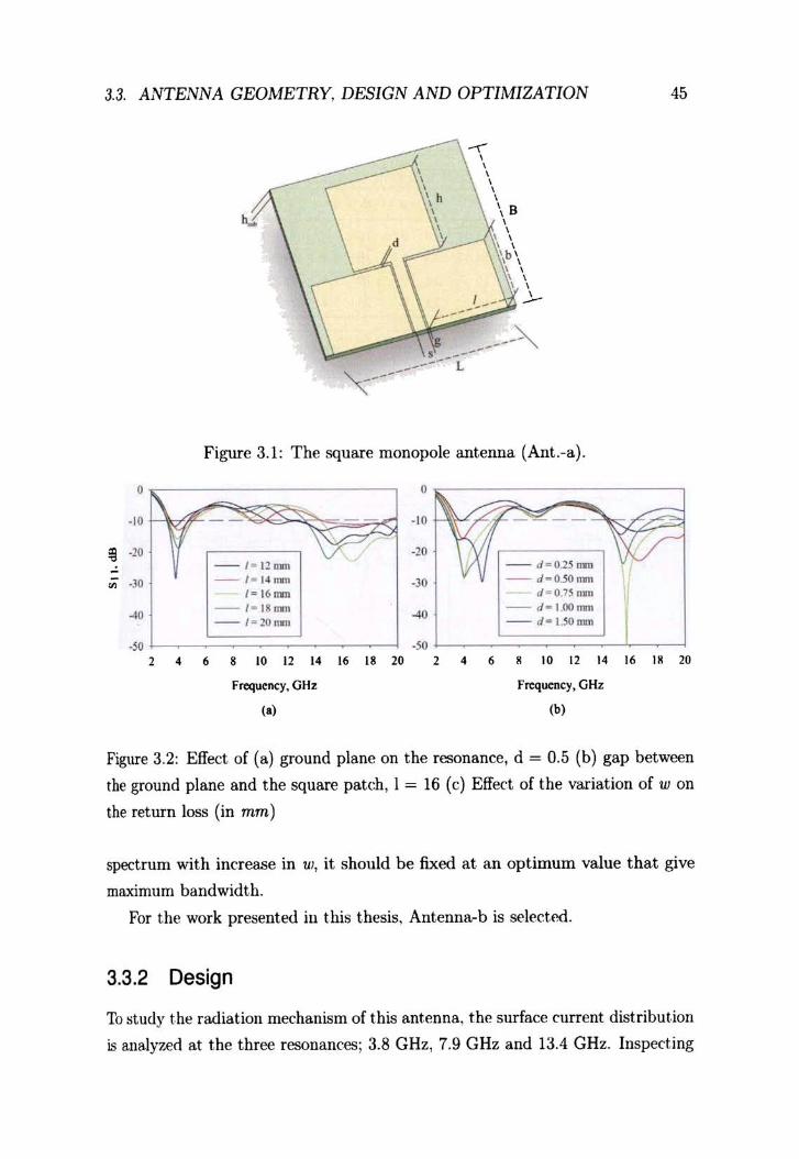
Geometry of the square monopole antenna is shown in Figure :L 1 and the ('orre
sponding parameters in Table ;j.l. This antenna. shows a single resonance as in
Figure :~.2 in accordance with a quarter wave variation in h. Figure 3.2(a) shO\vs
the effect of the ground plane in this resonance and Figure 3.2(b) that of the gap
between the ground plane and the square patch. It. is clear that these parameters
affect only the matching of the antenna.
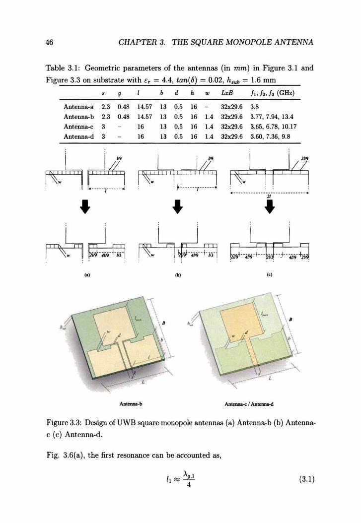
To design this antenna for ultra wide bandwidth, the design procedure outlined
in Figure 3.:3 is followed. As shown in Figure 3.:3(a), the ground plane \vith length
1 is divided in to 9 equal sections having ·width wand few sections in the ground
plane arc removed. This antenna can be designed with a microstrip feed either
as in Figure :3.3(b) or Figure :3.3(c). The return loss plots of these antennas are
shown in Figure 3.,) and the resonances are indicated in Table 3.l. Antenllas-b.(',J
with modified ground plane have wide impedance bandwidth and among them,
Ant.-b exhibits a superior performance in terms of the overall bandwidth. It has
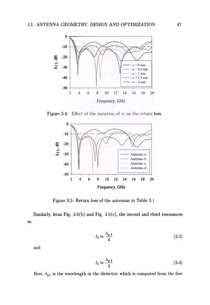
been seen, hov-.'ewr, that hy adjusting l, d and w. impedance bml(hvidths of
Antenna-c and d call be improvecl. A variation study performed \vith 'W is shown
in Figure 3.4. As w is increased, the second and third resonances merge and
improve the -lOdB bandwidth. Since the resonances shift to the Imver side of the
3.3. ANTENNA GEOMETRY, DESIGN AND OPTIMIZATION
• .,.
~ ·10
" • .,. ... .,.
2 •
-.-, , , , , , \ B , , , , _...,.:t---, \' , \b\ , , , , , ,
I _ _ J.-... ----
, -------~ ,,_----------L
Figure 3.1: The square monopole ant.enna (Ant.-a) .
• .,. ----.,.
-1- Uull! - d " O.lS Iml
- / - 14 11111 .,. - d - O.50nm / - 161ml si - O.7Snm
- 1- 18 1m1 ... - J - I 001Tl1l - / - 2Qtml -d-UOrrm
.5O
• 8 ,. 12 .. 16 " 2. 2 • • • 10 12 " Frequency, GHz Frequency, GHz
(.) (b)
45
16 " ,.
Figure 3.2: Effect of (a) ground plane on the resonance, d ~ 0.5 (b) gap between
tbe ground plane and the square patch, I ~ 16 (c) Effect of the variation of w on
the return loss (in mm)
spectrum with increase in UJ, it should be fixed at an optimum value that give
maximum bandwidth.
For the work presented ill t his thesis, Antenna-b is select.ed.
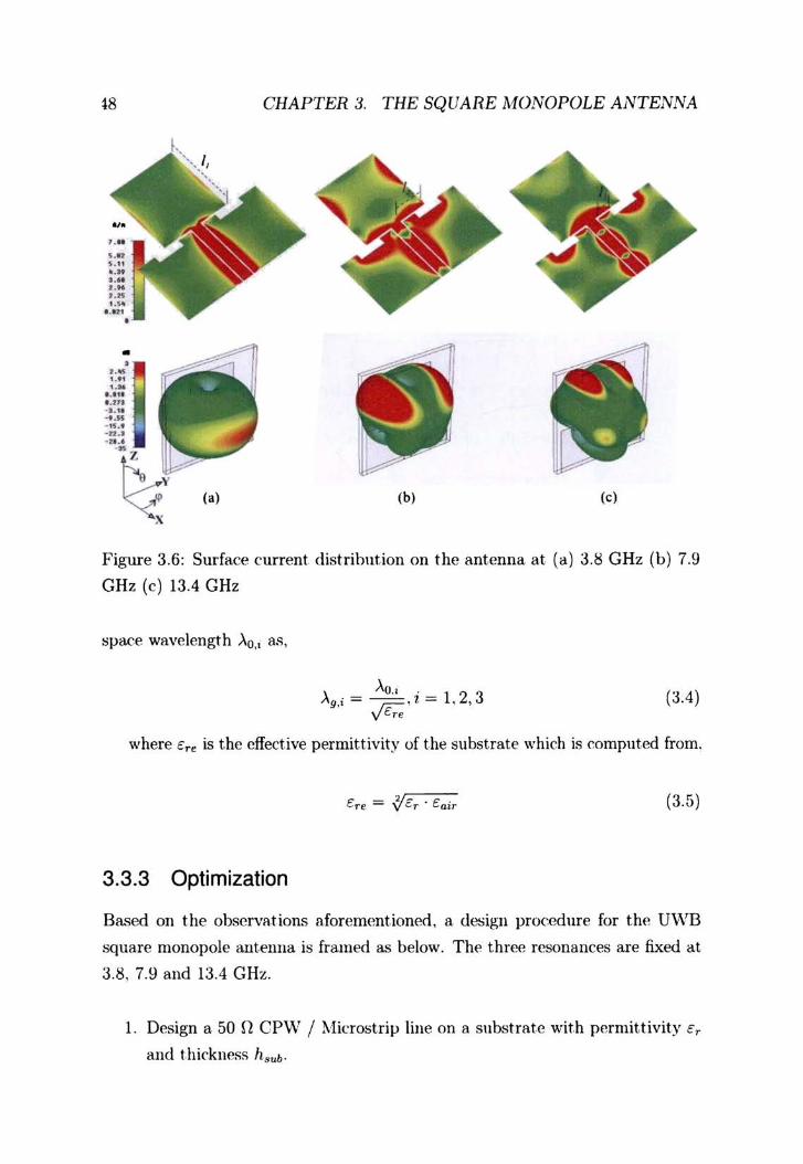
3.3.2 Design
To study t.he radiation mechanism of this ant.enna, the surface current distribut.ion
is analyzeci at the three resonances; 3.8 GHz, 7.9 GHz and 13.4 GHz. Inspecting
46 CHAPTER 3. THE SQUARE MONOPOLE ANTENNA
Table 3. 1: Geometric parameters of the antennas (in mm) in Figure 3.1 and
Figure 3.3 on substrate with er = 4.4 , tan,(6) = 0.02 , h, ub = 1.6 mm
, 9
Antenna-a 2.3 0.48
Antenna-b 2.3 0.48
Antenna-c 3
Ant.enna-d 3
, .... .. .. -1' ... .. ..
. ,
I b d h w
14.57 13 0.5 16 -14.57 13 0.5 16 1.4
16 13 0.5 16 1.4
16 13 0.5 16 1.4
I ll' I~. I i I Tt' I j,'4 : : f ..... ·.,--....• ..
~ ~ ~. ~ flr.d .. ~ , . 1·1
\. \\ , \ , ' .~
(b)
LxB h , h." (GHz)
32x29.6 3.8
32><29.6 3.77, 7.94 , 13.4
32x29.6 3.65, 6.78, 10.17
32><29.6 3.60, 7.36, 9.8
I ~. 1 1 . .. _- ----- - - ----- - ---- ------- - ..
11 .. 1 1
1<1
\., \ \ 8 \ '. b\ '1.
Antmna-e I Antenna-d
Figure 3.3: Design of UWB square monopole antennas (8) Antenna-b (b) Antenna
e (c) Antenna-d.
Fig. 3.6(a) , the first resonance can be accounted. as,
I ....... "\g.1 ,--4
(3.1 )
3.3. ANTENNA GEOMETRY, DESIGN AND OPTIMIZATION 47
as.
0
.\0
'" ·20 "" . - - .. ,· 0111111
'" ·30 - w - O.5 1lU1l w- Imm
-40 - w - I. S nun - ... - 2I11nl
.50 .l-~~-2~~_..!::::;===~ 2 4 6 8 10 12 14 16 18 20
Frequency, GHz
Figure 3.4: Effect of the variation of 1lJ on the retmn loss
'" "" ..:
'"
Or-----------,
·10 HIt-·~
·20
·30
-40
·50 2 4 6
-- AlllcrUla- a -- Antenna- b
ATlIenn3· c -- Amenn.1- d
8 \0 12 14 16 18 20
Frequency, GHz
Figure 3.5: Ret.urn loss of the antennas in Table 3.l
Similarly, from Fig. 3.6(b) and Fig. 3.6(e), the second and third resonanees
and
1 Ag.2 2'" - 4
A,3 13 '" _._. 4
(3.2)
(3 .3)
Here, Ag,i is the wavelength in the dielectric which is computed from the free
18 CHAPTER 3. THE SQUARE MONOPOLE ANTENNA
• • ..• ",t ...
I.'" I.'" ".1, ..... -,,0' . ., .. ' n .' ..
Z
(a) (b) (c)
Figure 3.6: Surface current distrihution on the antenna at (a) 3 . ~ GHz (b) 7.9
CHz (c) 13.4 CHz
spaC'e wavelength >'0" as ,
, '\0.. . 2 3 "g,i = r;:-,l = 1, ,
vEre (3.4 )
where Ere is the effective permittivity of the subst.rate which is computed from.
'f-ere. = v c.,. . cair (3.5)
3.3.3 Optimization
Based 011 the observations aforementioned, a de;ign procedure for the U\~lB
square monopole antenua is framed as below. The three resonances are fixed at
3.8, 7.9 and 13.4 GHz.
1. Design a 50 n CP\V I ~li<:rostri)J line on a substrate with permittivity er
and thickness h sub'
JJ .~HE!'i!'iA GEOMETRY. DESIGN AND OPTIMIZATION 49
Table 3.2: Antenna descript ion
Antcnna- l Alltenna~2 Antenna-3 Antennll·4 Antenna-S
Laminate Rogers Taconic FR4 Epoxy Rogers Rogers
5880 RP·30 R03006 6010LM
h, .. " 1.57 1.52 1.6 1.28 0.635
:,. 2.2 3 4.4 6.15 10.2
tU7I (6) 0.001 0.0013 0.02 0.001 0.001
,~ (mm) 2.3 2.3 2.3 2.3 2.3
9 (mm) 0.12 0.18 0.28 0.34 0.6
• 0
.\0 ·10
= ·20 -20 ~
~
~ .)0 -,-, .3<) -~-, --, - ............ ~ M-' M_'
"" -M~ -4, -M~ _M_' -M_' .,. .,. , 4 • • 10 12 14 16 " 20 , 4 • , 10 " " I. " 20
Fn:qucncy, GHz FrcqUCllcy, GHz
(.) (b)
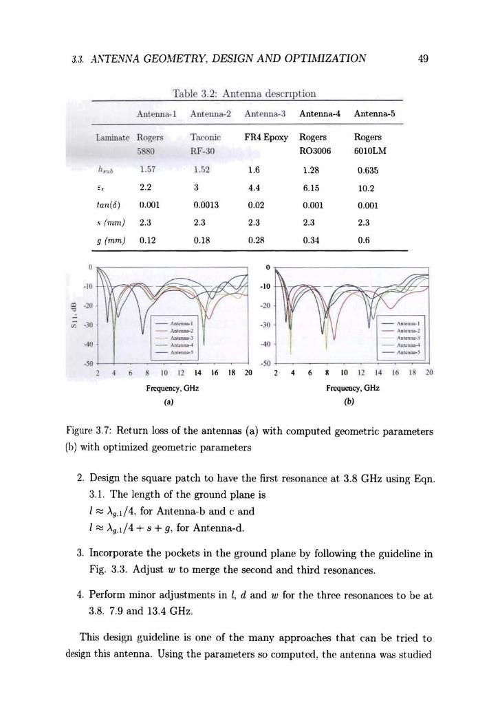
Figure 3.7: Return los. ... of the ant.ennas (a) with comput.ed geometric parameters
(b) wit.h opt imized geomet.ric parameters
2. Design the square pat(:h to haw the first resonance at. 3.8 GHz using £qn.
3.1. The length of the ground plane is
I ~ )..9,1/4, for Antenna-b and c and
I::::: >.g.I/4 + s + g, for Antenna-d.
3. Incorporate the pockets in the ground plane by following the guideline in
Fig. 3.3. Adjust w to merge the second and third resonanees.
4. Perform minor adjustments in l, d and w for the three resonances to be at
3.8. 7.9 and 13.4 GHz.
This design guideline is OOE'! of the many approaches that. can bE'! tried t.o
design this ant.enna. Using the parameters so computed, the antenna was studied
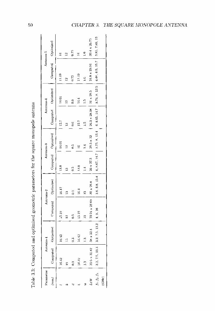
Tab
le 3
.3:
Co
mp
nte
d a
nd
opt
imiz
('d
geom
et.r
ic p
aram
eter
s fo
r th
e sq
uare
mon
opol
p an
ten
na
Par
amet
er
Au
t.en
na-
l Allt~lll1a-
2 A
nt.c
llua
<1
Ant
.enn
a-4
(mm
) C
Oll
lPut
ed
Op
tim
izeu
C
om
pu
ted
O
pti
miz
ed
Co
mp
ute
d
Opt
illl
izf'
d C
om
pu
ted
O
pti
miz
ed
I IG
.4:2
16
.'12
IG.H
l 16
.17
l:t8
14
.01
12.7
11
.01
b 15
1
;,
1:1
1 :1
1:3
1:1
B
13
d O
.:!
0.3
0.5
0.
;;
0.5
n.;'
(J.G
O
.G
h ](
i.·1~
16.1
2 15
.19
16.4
1:
1.8
IG
12.7
1,
1.4
In
1.3
1.3
1:1
13
1.4
1.1
1.5
I.!)
L:r
W
:!5.G
x :
HX
2
3H x
32.
1 33
.2,1
x 2
8(;
9
:15
x 2!
l.H
26 x
27.
3 29
.5 x
32
:26.
3 x
:2I'U
H
31 x
2!l
.5
ft·J
zJl
:1.:
2,7.
;;,1
:3.;
1 3.
2, 7
.5,
B.3
,I
, 9,
Hi
3.6.
8.8
. 15
.4
4, H
.67,
H.7
:1
.7;'
;.8
,13
.4
4. K
65
, 14
.7
,3.7
9, 8
, 13
.5
(GH
z)
I A
nte
nll
a-5
Comput.~d
Opt
.ill
lize
d
11.1
9 11
12
12
0.75
0.
75
11.1
9 14
I.G
1.6
2,1.
8 x
2:1.
94
:10.
4 x
26
.7"
4.4H
, 8.
9, 1
!i.7
3.
HS,
7.H
9,
13
c., ....
o 9 ~ 'V
~ ~ ~ ~ (f}
.0
c::: ~
~
t:r1
:;;-. ....... o :? ~ ,-.. '-'
t-<
t:r1 ~
?' ~ > ~ ~
3.4. BAND NOTCH DESIGN 51
on substrates \vith different permittivit.y, described in Table 3.2. Figure 3.7(a)
shows t.he return losses of the antennas \\'it.h the computed geometric parameters
given in Table :3.3. Resonances of these antennas show slight deviation from the
designed values but the bandwidth is almost similar for all the antennas except
for AntEmna-5. Due to the shift in the resonance towards the higher side. the
lower edge of the band has also been shift.ed and hence the designs needed to
be optimized to cover the 3.1- 10.6 U\VB. The optirnized design parameters are
tabulat.ed in Table J.J and the return loss is shmvn in Fig. 3.7(b). The slight
disparit.y in the computed and optimized design parameters can be attributed to
the ambiguity in the exact. val11e of Ere.
3.4 Band Notch Design
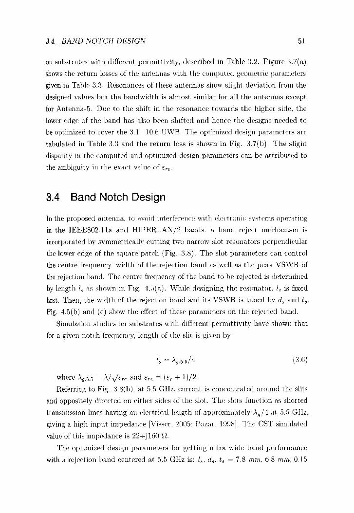
In the proposed antenna. to avoid int.erference with electronic systems operating
in the IEEE802.11a and HIPERLA~/2 ba.nds, a band reject mechanism is
incorporated by symmetrically cutting t.v.m narrmv slot resonators perpendicular
the lower edge of the square patch (Fig. :3.8). The slut parameters can control
the centre frequency. width of the rejection band as \vell as the peak VSWR of
the rejection band. The centre frequency of t he band to be rejected is determined
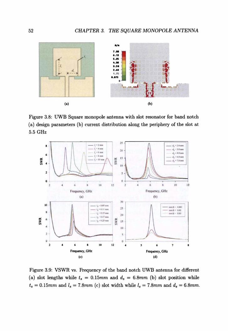
by length '.~ as shown in Fig. 4.5(3). \Vhi1e designing the resonator. 18 is fixed
first. Then, the width of the rejection band a.nd its VS\\TR is tuned by ds and ts.
Fig. 4.5(b) and (c) show the effect of these parameters on the rejected bcUlCl.
Simulation studies on subst.ratcs wit.h different permittivity have shown that
for a. given notch frequency, length of the slit is giwm by
(3.6)
where Ag.5.5 = A/..;s;; and Ere = (c~ + 1)/2
Referring to Fig. 3.8(b), a.t 5.5 GHz. current is concentrated around the slits
and opposit.ely directed on either sides of the slot. The slots fundion as shorted
transmission lines having an elect.rical length of approximately Ag /4 at 5.5 GHz.
giving a high input impedance [V"iSSCL 2()()5: Pozar. 1~)!)8l. The eST simulated
value of this impedance is 22+j160 O.
The optimized design parameters for getting ultra wide band performance
with Cl rejection ba.nd centered at. 5.5 GHz is: Is, d.~. t.~ = 7.8 mm. 6.8 mm, 0.15
52
l' : I, ,
Jv .-..-
CHAPTER 3. THE SQUARE MONOPOLE ANTENNA
,
d. 1< ---~
(.)
w. , ... '.tl •• &
;:~ ~ ~ un }: :r' . '-_::{ 'If 'C._ .J. , , r . , 1.....__ ••
(b)
Figure 3.8: UWB Square monopole antenna with slot resonator for band notch
(a) design parameters (b) current distribution along the periphery of the slot at
5.5 GHz
•
2
o ,
". , " , ~ ~ ,
0 2 •
•
-1, - 1-
-1,---1,-'-t-·-
• " Frequency, GH:t ,.,
_'. G"'_ _,._II.U_
'. 'U_ - ', gp-_',_lUJ_
• • " Frequency, Gttz
,<,
"
"
o
"
JO
" " ~
~ " ~
" • 0
"
_01,'11_
_,I, 31_ ~._H_
_.1, ' 6.1 _
_ 01,_11_
\ ) ~ , , • • " "
Frequency, GHz
(b,
-_"' 11.001 -_"-GoJ -. •• I
/'~ • • , •
Frequency, GHz
(d,
Figure 3.9: VSWR vs. Frequency of the band notch UWB antenna for different
(a) slot lengths while t. = O.15mm and d. = 6.8mm (b) slot position while
t, = O.15mm and I. = 7.8mm (c) slot width while I. = 7.8mm and d. = 6.8mm.

; 3.5. EXPERIMENT RESULTS 53
mm. Simulation studies have also shown that sharp notch edges and high VSWR
(> 15) can be obtained if low loss substrates are used.
3.5 Experiment Results
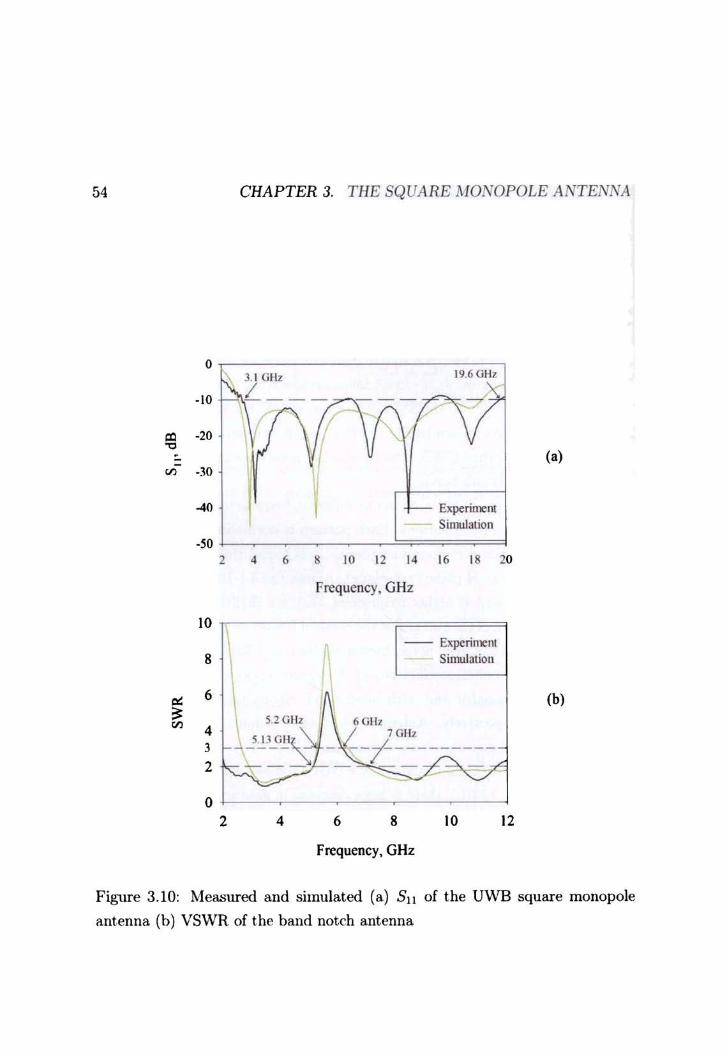
Measured return loss of the U\VB square IIlonopole antenna shown in Fig. 3.1 O( a).
The plots are in agreement at the lower frequencies alld t.he slight variation at the
higher side could be due to the S~IA connector. which, has not been accounted
in the simulation. As shown in Fig. 3.1O(b), measured and simulated VSWR
plots of the band notched UV/B antenna also has good agreement and is high (>
3) in the 5.2 - 6 GHz sub band.
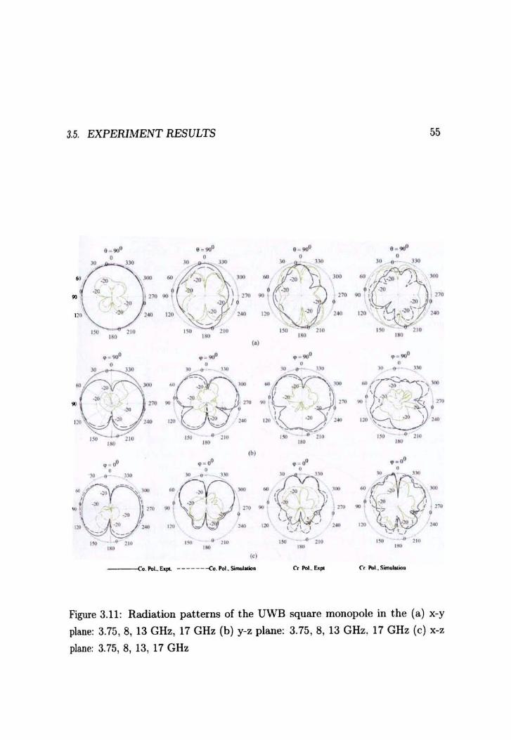
Radiation patterns of the antenna at diff(~rent. frequencies are shO\vn in Fig.
3.11 for co and cross polarizations. Each pattern is normalized with respect to
the peak value of the corresponding plane. It is found t.hat. the patterns are
omnidirectional in the H-plane (x-y plane). Across the 3.1-10.6 GHz U\VB, t.he
patterns are stable and at higher frequencies, they are slightly distorted.
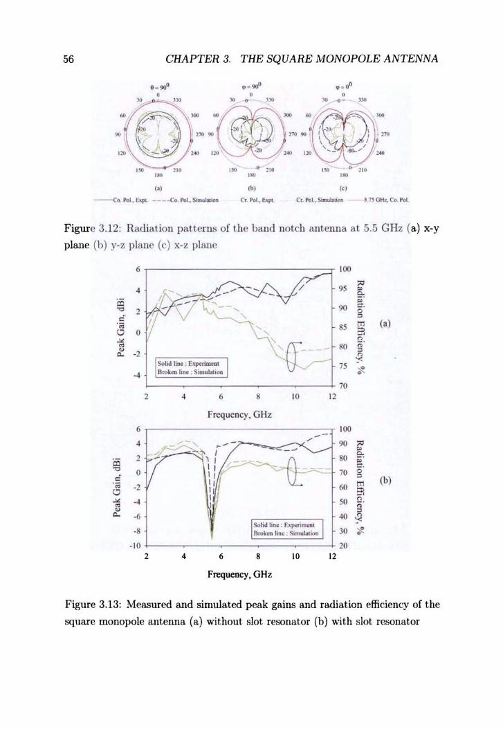
Radiation pattern of the ant.enna at the notched frequency is shown in Fig. 3.12.
Pattern at 5.5 GHz has been normalized W.r.t that. at 3.75 GHz for comparison.
Measured gain and radiation dfici('ncy of the square mono pole antenna without
the band notch resonator and with band notch resonat.or is shown in Figure
3.l3( a) and (b) respectively. Antenna polarization is found t.o be along the z
direction. l\Ieasured gain remains const.ant t.hroughout the band and the average
value is found to be 3.75 dBi in t.lw 3.1-10.6 GHz band as shown in Figure :3.13(a).
As shown in Figure :U 3(b), there is large decrease in gain when there is a band
rejection mechanism as low as -9dB compared to the rest of the band. l\Ieasured
radiation efficiencies are also reasonably good and is in agrement with simulation.
54
'" '" 0 -'"
'" ~ '"
0
- 10
-20
-30
-40
CHAPTER 3. THE SQUARE MONOPOLE ANTENNA
I
19.6GHz
Experiment Simulation
(a)
-so l-_~ ____ -'=-=====i
10
8
6
4 3
2
0
2 4 6 8 \0 12 14 16 18 20
Frequency. GHz
, -- Expcrin'K:nt Simulation
52 Gllz 6 Gllz
.Ji~J_G.!:'~ 7GHz
-/----------""" -
2 4 6 8 10 12
Frequency, GHz
(b)
Figure 3.10: Measured and simulated (a) SII of the UWB square monopole
ant-enna (b) VSWR of the band notch antenna
3.5. EXPERIMENT RESULTS 55
..... e ~9IP • ... ..... , , , , " ." " • ." -, .. ~ '/"' 1 "" .. ~ '00 00 ...
.,., .. r .. • .. I !70 ... " . no ·lO • • .,.
'" '" " ,~ ,,. ,~ ,,. -'--.. '" '" 210 ,~ '" '" , .. ,. ,.
to) ..... ..... • ..' • ... , • • • " '" • • •• • ~- • • • • .. --" Q "(- ~
-, ... . ' • .,. , •• m .. .. • m
" • , ,. ,,. , '" , -----' ,. • !IO ,M • '" ,. • ,.
'" ,. ,. ,.
(bI .... •• 00 • " ....
• • • • • • ~ • • ••
D • ·w- " t·1O "I ... .. ~
, , .,. • \ '''t, I • j l:'t ,. l'll) • r '" .,. I:' . :..
. , \_ 'I ,. ~
,,. \ " 1- ,. '" '" -" '''' ,. -, JIG ,. • ,. ,. • '" •• '" ,. •• , . ,.
t" Co. N .. ElJIl -------<o . .. oL~ e. 1'01 .• Ex", (',"-' .. s,""' .....
Figure 3.11: Radiation patterns of the U\VB square monopoie in the (a) x-y
plane: 3.75. 8, 13 CHz, 17 CHz (b) y-z plane: 3.75, 8, 13 CHz. 17 CHz (c) x-z
plane: 3.75, 8. 13. 17 CHz
56 CHAPTER 3. THE SQUARE MONOPOLE ANTENNA
e. !100 •• ,.p • • 0' • • • ~ ,~ ~ .- ,~ ~ ,- ,~ .. ,.,
/","lIl' -....:
~ ". ~ no 90 m
• ,~ l~ ' ,~ ,~
,~ '" ,~ • ~lO ,~ • '" , .. ,0> ,. t.) ~) ,,,
-Co P<JI . E>.pl --_-Co. PoLSimubboa C. Po! . Eopl. Cr. PoI .. S"" .. lalian - 3 75 mu, Co. Pal
Figure 3. 12: Radiation patterns of the band notch antenna at 5.5 GHz (a) x-y
plane (b) y-z plane (c) x-z plane
6 tOO
/ 95 '" 4 - ~ ~
co 90 ~.
~ 2 0
" " .~ SS en ('l 0 0 , '" ~
, o. ~ 80 a 0 " "- -2
" 75 ~ -4
70 , 4 6 8 !O !2
Frequency, GHz
6 100 -4
co 2
" 0 0 .~ -2 0 ~ -4 .. 0
"- -6
·8
; ; .-
~ I -7
'I I _- __ 0;>-II V
II I I '-II I I
I ~I id 11"", : F..:lpmmcnl I I Broken line , Simut.lic>n
90 '" • 80
e, ~ 7. 0· " (b)
60 en
'" 50 o. 0
" 40
" 30 ~
-10 20 2 4 6 8 10 !2
Frequency, GHz
Figure 3.13: Measured and simulated p~..ak gains and radiat ion efficiency of the
square monopoie antenna (a) without slot resonator (b) v..ith slot resonator
3.6. CONeL USION 57
3.6 Conclusion
A Square l\Ionopole Antenna ,,,,it h ultra wide band'width is designed and character
ized in this chapter. U\VB is achieved by a novel ground modification technique.
which minimize pernicious reflections 'within the antenna structure. This antenna
can be designed on any commercially ava.ilable microwave la.minate since universal
design guidelines are available. Impedance bandwidth of the antenna is from
3.1-19.6 GHz with stable radiation pat.terns and gain in the 3.1-10.6 operationa.l
band. A band notch technique is also proposed to limit interference with \VLAN
systems, which is tunable.
References
ALOMAINY A., PARI!'\1 C. G., HALL P. S. 2005. CornpaTison bet.ween two different antennas for
uwb on-body propagation measurcments. IEEE Transaction on Antennas and Pr'opagation,
4, 31-34. :~t\
AMMANN, :-lAX J. 200l. Cont.rol of the impedallce bandwidth of wideband planar monopole
antennas using a beveling technique. Microwave and Optical Technology Letters, 30(4),
229-232. ;{4
AMMAi'N, IVI AX J. 200:3. A wide-band shorted planar monopole with bevel. IEEE Transaction
on Antennas and Pmpagation. 51(4). 901-903. :34
ANoB P. V., RAY K. P., GlREESH Kt1MAR. 2001 (July). Wideband orthogonal square
monopole antennas wit.h serni-t:ircular base. In; IEEE Antennas and Pmpagation Society
International Symposium. :-Il.!l
ANTONINO-DAVIlT E., :-1. CABEDO-FABRES, 11. FF:RRANDO-BATALLER-A. VALERO
NOGlJEIRA. 2003. Wideband double-fed planar monopole antennas. lEE Elfxt1'Onics Letters,
39{November). 1fi:{5-1636. :34
CARTER, P. S. 1939a. Short wane antenna. US Patent 2. 175, 252. :)4
CARTER, P. S. 19::l9b. ~Flde band .~hort WU'l'e antenna and transmission system. US Pat.ent 2,
181,870. 34
CHEN, ZHI KI:'llG. 2005. Xovel bi-ann rolled monopole for UWB applications. Mir.mwaVi' and
i Optical Technology Letter8, 44( 4). 294 295. ;-\5
r: CHEN .YING, Y. P. ZHAl\"G. 200:). A planar ant~~l~a in ltce for sin~le-pa~kag(' ~Itrawide-band I radio. IEEE Transactwn on A ntennas and Propagatwn, 53(9), 3089-.3093. ,-II'
58 REFERENCES
CIIIH-Yl' HUANG. \VEI-CIIC:-.I HSIA. 20D7. Plftnar ultra wide bftnd antenna with a frequency
notch characterestic. Microwave and Optical Technology Letter's, 49(2). 316-:l2D, -i1
CHI:-.1G-Hsl:-':G Luo. CHIEN-1.1I:-.IG LEE, \VEN-SHAN CHEN-CHIH-Ho Tu YI1'\G-ZO)lG JllANG,
2007. Dual hand notched ultra widehand monopole antenna with an annula cpw feeding
structure. Microwave and Optical Technology Letters, 49(10). 2376-2:379, 42
CHI:-\G \VEI LING. \VE:-\ HSIN Lo, RAN HO]\;G YAN-SHYH .10)lG Cmr:'>lG. 2007. Planar
binomiftl curved monopolf' antennas for ultrawideband communication. IEEE Transaction
on Antennas and Pmpagation. 55(9), 2622-2624. 42
CHONG Yl' HOXG. CHIl\'G WEI LIl\'G, 1-YOt'NG TARl\'-SHYH .lONG CHU:>IG. 2007, Design of
et planar ultrawideband antenna with a new band-notch structure. IEEE Tmnsadion on
Antennas and Pmpagat·ion. 55(12),3391-3397.-1:3
ELDEK. ABDEL!'lASSER A. 2007. Ultrawidebund double rhombus antenna with stable radiation
patterns for phasf'd array applications. IEEE Transaction on Antennas and Propagation,
55(1),84-91. 41
FRAXCIS JACOB K., Se:\L\ ~1. N .. ROHITH K. RAJ-!\lANOJ .10SEPH 1.iOHANA:-\ P. 20D7.
Planar branched monopole antf'nna for U\VB applications. Microwave and Optical Technology
Letters, 49(1), 45-47.10
GEORGE THO:-'IAS K., LE~IX I"., SIVARAMAKRISH)lAl': R. 2006. Ultrawidehand planar disc
lIlonopole. IEEE Transaction on Antennas and Propagation, 54(4). 13:19-13-i1. :3(;
GIL'SEPPE RL'VIO. ~IAx .1. Ar-.lXIANN. 2007. A novel wideband semi-planar miniaturized
antenna. IEEE Transaction on Antennas and Propagation. 55(10). 2679-2685. :\7
GUOFEXG Le. STEFA!'l VON DER ~vlARK. ILYA KORISCH LARRY J. GREE;-';STEI!'l PREDRAG SPA
SOJEVIC. 2004. Diamond and rounded diamond antennas for ultrawide-band communications.
IEEE Antennas and Wireless Propagation Letters, 3, 249-252. :{~
IREJ'\E AJ'\G. Oor B. L. 2007. An ultra wide-band stacked microstrip patch ant.enna. Microwave
and Optiral Technology Letters, 49(7). 1659- lUGS. :37
JAEWOOXG SHIl\'. SEOK.JIX HOj\;G. JAEHOO!'l CIIOt. 2007. A compact internal U\VB antenna
for wireless USB dongle application. Aficrowave and Optical Ter.hnology Letters. 50(6),
164:\-1646. :{7
JIA~:\U[\;G QIC. ZHEJ'\GWEI Dt 1 • JIA",Hl'A Lt' KE GO:-<G. 2005. A hand-notched uwh antenna.
Microwave and Optical Technology Letters. 45(2). 152-1.54. :{5
JIA~XIN LIANG. CHOO C. CHIAtT. XIAODO;\lG CHEX CLIVE G. PART:\1. 2005. Study of a
printed circular disc monopolc antenna for uwb systems. IEEE Tmnsaction on Antennas
and Propagation, 53(11), 3.500-:{504. :{I'l
REFERENCES 59
JIN-PING ZIIANG, Ytr;-;-SIIF;;-;G Xe, \VEI-DONG \,vANG. 2007. l\Iicrostrip~fpd semi-elliptical
dipole antennas for ultrawideband communications. IEEE Transaction on Antennas and
Propagation, 56(1), 241-244. ,n
JOERI R. VERBIEST, GUY A. E. VANDEi\BOSCH. 2005. A novel small-size printed tapered
monopole antenna for U\VB \VBAN. IEEE Antennas and Wireless Propagation Letters, 5,
377-379. 38
KA-LEUNG LAu, PEI LT, KWAT-~IAN Lt·K. 2005. A rnonopolar patrh antpnna with very wide
impedance bandwidth. IEEE Tmnsactwn on Antennas and Propagation. 2(,53), 655-661. ;~6
KEYVAN BAHADORI. YAHYA RAHMAT-S,UIIl. 2007. A miniaturized elliptic-card UWB antenna
with WLAN band rejection for wireless COIlllnuuications. IEEE Transaction on Antennas
and Propagation, 55(11), ;~326-:j332. cl:)
KIN-Lu WONG, YI:N-\VEN CHI, CIlIJ[-~IING SI: FA-SHIAN CHA:"'G, 2005a, Band-not.ched
ultra-wide band drcular-disc rnonople antpnna wit.h an arc shaped slot. Alicrowave and
Optical Technology Letters. 45(8), lR8 191. :j!)
KIN-Lu \VOI\G, LIAI\G-CHE CHOL'. Ho;,-;(;-TWl} ClIEN. 2004a. Ultra-widc band metal plate
monopole antenna for laptop applicat.ion. 1lIic'f'O'Wuvc and Optical Technology LdtfTs, 43(5),
384-386. 35
KIN-Lv \\'01\'G, Tr~G-CHlH TSENG, PEy-LI:".a; TEXC. 2004b. Low profile ultra-wide band
antenna for mobile phone applications. Microwave and Optical Technology LetteTs, 43(1),
7-9. 35
KIN-Lu WONG, CHIH-HsIEN Wc. SAOL'-WEN (STEPHE1':) Sll. 2005b, Ultrawide-band square
planar metal-plate monopole antenlla with a trident-shaped feeding strip, IEEE Transaction
on A ntennas and Propagation, 53(4), 1262-1268. :3-1
KURAMOTO, AKTO. 2006. Flat type uwb antenlla consisting of two kinds of elliptical elements
located in parallel. Electronics and Comrn'IITlirations in Japan, 89(12), 54-61. :39
LEE E., HALL P. S., GAIW:-IER P. 1999. Compact widehand planar monopole antcnna. lEE
Electronics Lette,s, 35(25), 2157-2158. 34
LEE PAULSE:-:, JAl\IES B. \YEST. W. F. PERGER .1 OH 1': KRAt'S. 2003 (June). Recellt investiga
tions on the Volcano Smoke Antenna. Pages R45 R48 of' IEEE Antennas and Propagation
Society International Symposi1lm, vol. 3. :3.J
LODGE, OLlVER, 1898. Electric Telegraphy, US Patent 609, 154. ;~l
Low Z. ~ .. CHEOI\G .1. H., LA\v C. L. 200!'i. Low-('ost PCB antenna for UWB applications.
IEEE Antennas and Wireless Propagation Letters. 4. 2:37-239. :38
60 REFERE}\lCES
Lt: G .. SPASOJEVIC P., GREENSTEIN L. 2003 (August). Antenna and pulse designs for
meeting UWB spectrum density requirements. In: IEEE ConJ. Ultra Wide band System,~ and
Technologies, vo!. 4. :{H
11AcIE.J KLEl\lM, GERARD TROESTER. 2006. Tf'xtile UV\TB antennas for Wireless Body Area
Ketworks. IEEE Transact'iun on Antennas and Propagation, 54(11), ::n92-3197. -to
:\I!CIIlTAKA A~1EYA. MANATW YAI\]AMOTO. TOSHIO l'\OJnlA KIYOHIKO ITo. 2006. Broadband
printed dipole antenna employing self -complementary radiating elf'll1ent and mirrostrip line
feed. Electr'onics and Communications in Japan, 82(12), 62-74. ;30
)JADER I3EHDAD, KAMAL SARABAI\'DJ. 2005. A compact. antenna for ultrawide band applica
tions. IEEE Transaction on Antennas and Propagation, 53(7).2185-2192. ;-Hf
l'\ARAYAX PRASAD AC;ARWALL. GIRISH Kl.'!\!AR. RAY K. p, 1098. \Vide-band planar monopole
antennas. IEEE Tmnsactions on Antennas and Propagation, 46(2),294 2%. :H
XIKOLAY TELZIIEJ\SKY, YEHL'DA LEVIATAI\'. 2006. l'\ovcl method of U\VB antenna optimization
for specified input signal forms by means of gf'netic algorithm. IEEE Transaction 011 Antennas
and Propagation, 54(8). 2216 2225. :1fi
XTSA:--'DERH C. AZEXl11, YANG H. Y. D. 2007. A printed crescent patch antenna for
ultrawideband application:;. IEEE A ntennas and Wireless Propagation Letters, 6, 11:1-116.
10
PEYROT-SOLlS 1\1. A., GALVA]\;- TEJADA G. :\1.. JARDON-AGl.1ILAR H. 2006. A novel planar
U\VB monopole antenna formed on a printed circuit uoard. Microwave and Optical Technology
Letter's, 48(5), 933-9;15. ;m
PEYROT-SOLlS 1\1. A., TIRADO-MENDEZ .), A., JARDON-AGllILAR H. 2007. Design of
rnultiuand U\VB planarized mOIlopo\e using DMS technique. IEEE Antennas and Wireless
Propagation Letters, 6, 77-79, 10
POZAR, DAVID 1\'1. 1998. Microwave Enginef.'f'ing. John WHey & Sons Inc .. New York. 51
RUIBATHl K .. THIAHT H, A .. I30R:'-lEMAN:\ J. YI' S. Y. 2006. Ultrawideband print.ed-cirCllit
antenna. IEEE Transactions on A'f/.teTlna~ and Propagation, 54(12), 390R-391l.1O
REZA ZAKER, CHA:-':GIZ GHOBADI. JAVAD )J(){IRI:-\IA. 2008. )Jovel modified U\VB planar
ll1011opole antenna with variablf' frf'qUf'llCy band-Hotch function. IEEE A ntenna8 and lVirdcss
p.mpagation Letters. 7, 112·114.J;~
SACHIN Gl."PTA, RA:--'lESH 1\1" KALGHATGI A. T. 2006. Ultra wide band f'rnbedded planar
inverted LOllical antenna. Microwave and Optical Technology Letters, 48(12), lIj9R-170l.W
REFERENCES 61
SANG-Ho LEE. Jll:-.lG-\VOO BALK, YoU:,w-SrK KI!\L 2007. A coplanar waveguide fed monopole
ultra wide band antenna having band-·notched frequency function by two folded strip line.
Microwave and Optical Technology Letter's, 49(11), 2747 2750 .. J:{
SAOU-~rEN (STEPHEl'\) Sll, Jlll-Hl:l'\G CHOU, Krl'\-Lll \VOl'\G. 2007. Internal ultrawideband
monopole antenna for wireless USB dongle applications. IEEE Transactions on Antennas
and Propagation, 55(4). 2216-2225. :l7
SAOU-WE:-.I Sc, KIN-Lll \VONG, Cr-lIA-LuN TANG. 2005a. Band-notched ultra-wideband
planar-monopole antenna. Microwave and Optical Technology Letters, 44(:3), 217 219. :3.5
SAOU-WE:--I StT, KIN-Le WOl'\G. 2005b. Broadhand omnidirectional U-shaped metal plate
monopole antenna. IEEE Transactions un Antenna .. ~ and Propagation, 53(2), :Hiri-369. ;)'J
SAOU-WE:--I SUo KIN-Le WO):G, YUA:\- Tl'N(; CHF;NG \VE:\-SHYA:\G CHEN. 2004. Finite
ground plane effect.s on the ultra-wide band planar monopole antenna. Aficrowalle and
Optical Technolug:tJ Letters, 43(6), 535-537. ;35
SAOU-WEN Se. Al'STI:--I CHEN. YUf\:C-TAO Lru. 2007. Wide band omnidirectional L-shaped
monopole antenna for a wireless USB dongle. Microwave and Optical Technology Letter's,
49(3), 625-628. :)7
SCHANTZ H. G., Fl'LLERTO:\ L. 2001 (August). The diamond dipole: A gaussian impulse
antenna. Pages 100-103 of: IEEE Antennas and Pmpagation Soc. Int. Symp., vo!. 4. :n
SHI-WEI Qu. JIA-LIN LI, QUA:--I Xl·E. 2006. A band-notched ultrawideband printed monofJole
antenna. IEEE A ntennas and Win less PmpagatioTl Letters, 5, 495-498. :)9
SHUN-YUN Lr:\', KCANG-CHIH HCA:\G. 2006. Printed pentagon IIlonopie antenna with a
band-notched function. Microwave and Optical Technology Letters. 48(10), 2016-2018. :)9
STOHR, \V. 1968. Bmadband ellipsoidal dipole antenna. US Patent 3, 364, 491. 3-1
STUTZMAN, \VARRE~ L. John Wiley & Sons Iuc. ;)·1
TUTKl' KAHACOLAK, ERDEl\! TOPSAKAL. 20Ofi. A double sided rounded bow-tie antenna
(DSRBA) for U\\'B communication. IEEE Antennas and Wireless Propagat'iun Letters. 5.
446-449. :39
TZYH-GHCA:--IG :\IA, Sl':\G-.1l·:\'G \\'tT. 2007. Ultrawidpband hand-notched folded strip lIlollopole
antenna. IEEE Transact'ion un Antennas Qnd Propagation, 55(9).247:1-2478 . .12
VALDERAS D., CE:\,OOYA 1.. BERE:'\Gl.'ER R. SAXCHO I. 2006. A method to opt.imize the
bandwidth of U\\,B planar monopole antennas. Microwave and Optical Technology Letters,
48(1). IriS 159. :)(i
62 REFER.E1VCES
VALDERAS D .. IVIELE]\'DEZ J., SM\"CHO I. 2005. Some design criteria for UWB planar mOllopole
antennas: Application to a slotted rectangular monopole. Microwave and Optical Technology
Letters, 46(1), 6-11. :-\!)
VISSER, HCBREGT J. 2005. Army and phased array antenna basics. l\'ew York: John Wiley &
Sons Inc. 51
\VEI-Yl: LI. KIX-Ll' "VONG. SAOL:- 'WEN Sll. 2007. Ultra wide haIld planar dipole ant-enn
with two C'shaped arms for wireless communications. Microwave and Optical Technology
Letten;, 49(5). 1132-1135. ·-1:2
\VEINER, I\lELV]~ 1\1. 2003. Monopole Antennas. Ma[{~el Dekker Inc., :-.rew York. :33
XllAN Hn \Vt:, AHl\'1ED A. KISHK. 2008. Study of an Illtrawideoand omnidirectional rolled
monopole antenna with trapezoidal cuts. IEEE Tran.mciwns on A ntennas and Propagation,
56(1), 1449-1451. :37
XL:AN HL'I \Vu. ZHl KING CHEl'\. 2005. Comparison of planar dipoles in U\VB applications.
IEEE Transactions on Antennas and Pmpagation, 6(.53), 1973-1983. ;-\!)
YI DIl'\G, GUA:'I/G-I\JJ;IIG \\'Al\G, JJAN-GAl\G LIAI\G. 2007. Compact. band notched ultra wide
band antenna. Microwa'Uf and Optical Technology Ldters, 49(11), 311-313. -n
YI-I\!IN LLf, Xl.'E-XIA YANG. GUO-XJ;II ZHEI\G. 2007. Analysis on a novel ultra wide handwidth
antenna of double printed circular disc. Mir:rowat'e and Optical Technology Letters, 49(2),
::111-:31:1. Tt
YILDIRIl\1. BAHADIR S. 2006. Low-profile and planar antenna suitable for wlan/bluetooth and
Ilwb applications. IEEE Transaction on Antennas and Propagation, 5, 438--441. :)9
YOl'NG JVN CHO, KI HAK KIM, DONG HYCK CHOI SEl'XU SIK LEE SI:;OXG-OOK PARK.
2006. A miniature UWB planar monopole antenna with .5-Ghz band-rejection filter and
the time-domain characteristics. IEEE Transactions on Antennas and Propagation, 54(5),
1453 ·1460. ;)9
Ye-Jw:'l/ HEN, KAI CHANG. 2006. An annual ring antenna for U\"B comIllunications. IEEE
.4 ntennas and Wirele.~s Propagation Letters, 5, 27 4-276. ;~k
YCE PIXG ZHA;IIG, QIA]\'G LI. 2007. Performance of U\"B impube radio with planar monopoles
over OIl human body propagation channel for wireless body area lletworks. IEEE Transactions
on Antennas and Propagation, 55(10), 2g07-2014.!2
ZHI ;\ING CHEl'. TF:RE:-.rCE S. P. SEE. XIANJ\.f1XC; QI:\C;. 2007. Small printed ultmwideband
antenna with reduced ground plane dIed. IEEE Transactio7L8 on Antennas and Pmpagation,
55(2), 383-388. -il


![A PERTURBED CIRCULAR MONOPOLE ANTENNA WITH CIRCULAR POLARIZATION … · A circularly polarized square slot antenna loaded with a cross patch is published in [8]. Here, a perturbed](https://static.fdocuments.net/doc/165x107/5b7b97d87f8b9a184a8cedfa/a-perturbed-circular-monopole-antenna-with-circular-polarization-a-circularly.jpg)
![Planar monopole antenna with offset square split ring ... · the bandwidth of the monopole antenna, include the feed, radiator or ground modification [1], [9], applying fract. al](https://static.fdocuments.net/doc/165x107/6041bd48d9bad90873554b2e/planar-monopole-antenna-with-offset-square-split-ring-the-bandwidth-of-the-monopole.jpg)


