
Chapter 3 - System Architecture · Chapter 3 System Architecture ... † Network Topology...
44
CHAPTER 3-1 Connected Utilities - Field Area Network 2.0 Design and Implementation Guide 3 System Architecture This chapter describes the FAN architecture for AMI with IOK in the head-end and the system components, along with their specific roles in the architecture, and design specifications. This chapter includes the following major topics: • System Topology, page 3-1 • System Components, page 3-3 • System Design Specifications, page 3-7 • FAN—Network Infrastructure and Routing, page 3-8 • FAN Network Management, page 3-23 • FAN—Security, page 3-32 • FAN—High Availability, page 3-41 • FAN—Sizing and Scaling, page 3-42 • Architecture Summary and Implementation Guidelines, page 3-42 System Topology Figure 3-1 shows the overview of the system topology.
Transcript of Chapter 3 - System Architecture · Chapter 3 System Architecture ... † Network Topology...
Design and Implementation Guide
C H A P T E R 3
System ArchitectureThis chapter describes the FAN architecture for AMI with IOK in the head-end and the system components, along with their specific roles in the architecture, and design specifications.
This chapter includes the following major topics:
• System Topology, page 3-1
• System Components, page 3-3
• System Design Specifications, page 3-7
• FAN—Network Infrastructure and Routing, page 3-8
• FAN Network Management, page 3-23
• FAN—Security, page 3-32
• FAN—High Availability, page 3-41
• FAN—Sizing and Scaling, page 3-42
• Architecture Summary and Implementation Guidelines, page 3-42
System TopologyFigure 3-1 shows the overview of the system topology.
3-1Connected Utilities - Field Area Network 2.0
Chapter 3 System Architecture System Topology
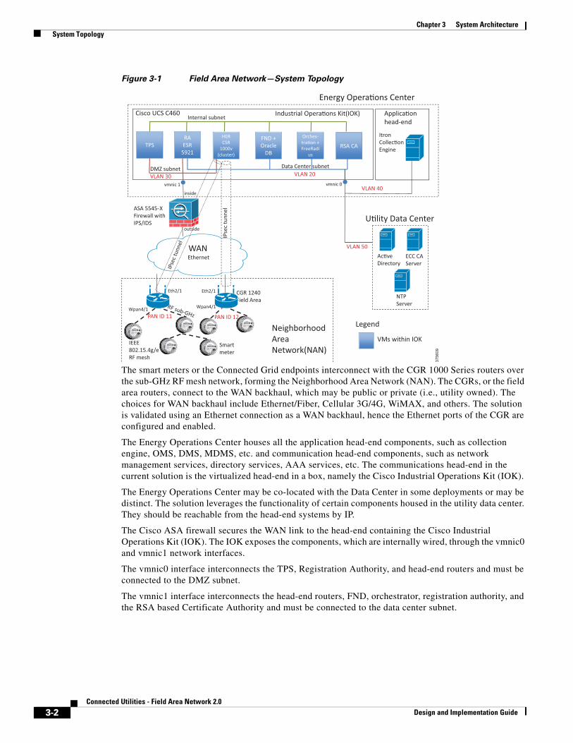
Figure 3-1 Field Area Network—System Topology
The smart meters or the Connected Grid endpoints interconnect with the CGR 1000 Series routers over the sub-GHz RF mesh network, forming the Neighborhood Area Network (NAN). The CGRs, or the field area routers, connect to the WAN backhaul, which may be public or private (i.e., utility owned). The choices for WAN backhaul include Ethernet/Fiber, Cellular 3G/4G, WiMAX, and others. The solution is validated using an Ethernet connection as a WAN backhaul, hence the Ethernet ports of the CGR are configured and enabled.
The Energy Operations Center houses all the application head-end components, such as collection engine, OMS, DMS, MDMS, etc. and communication head-end components, such as network management services, directory services, AAA services, etc. The communications head-end in the current solution is the virtualized head-end in a box, namely the Cisco Industrial Operations Kit (IOK).
The Energy Operations Center may be co-located with the Data Center in some deployments or may be distinct. The solution leverages the functionality of certain components housed in the utility data center. They should be reachable from the head-end systems by IP.
The Cisco ASA firewall secures the WAN link to the head-end containing the Cisco Industrial Operations Kit (IOK). The IOK exposes the components, which are internally wired, through the vmnic0 and vmnic1 network interfaces.
The vmnic0 interface interconnects the TPS, Registration Authority, and head-end routers and must be connected to the DMZ subnet.
The vmnic1 interface interconnects the head-end routers, FND, orchestrator, registration authority, and the RSA based Certificate Authority and must be connected to the data center subnet.
3756
09
TPS RA ESR
5921
FND + Oracle
DB
Orches-tra�on + FreeRadi
us
RSA CA
Energy Opera�ons Center
U�lity Data Center
Neighborhood Area Network(NAN)
vmnic 1 vmnic 0
ECC CA Server
Ac�ve Directory
WAN Ethernet
Industrial Opera�ons Kit(IOK)
NTP Server
CGR 1240 Field Area
ASA 5545-X Firewall with IPS/IDS
IEEE 802.15.4g/e RF mesh
DMZ subnet Data Center subnet
Internal subnet
Smart meter
Itron Collec�on Engine
HER CSR
1000v (cluster)
HER CSR
1000v (cluster)
VLAN 30 VLAN 20
VLAN 40
PAN ID 11 PAN ID 12
Wpan4/1 Wpan4/1
Eth2/1
Eth2/1
inside
outside
VLAN 50
Applica�on head-end
IPse
c tu
nnel
Cisco UCS C460
Legend
VMs within IOK
3-2Connected Utilities - Field Area Network 2.0
Design and Implementation Guide
Chapter 3 System Architecture System Components
System Components This section describes the components used in the solution and their functional roles.
Cisco Industrial Operations Kit (IOK) ComponentsThe IOK software bundle is installed on a single physical server after considering the necessary criteria outlined in the Industrial Operations Kit Management Software User Guide. The Cisco UCS C250 M2 Dual 3.0 GHz E5-2690 is recommended for IOK.
It is recommended to use VMware ESXi v5.1 or v5.5. Customization of the internal design and networking elements of IOK is not recommended.
The following components exist as virtual machines within the Cisco IOK.
Cisco IoT Field Network Director (FND) with Oracle Database
The Cisco IoT Field Network Director (formerly called Connected Grid Network Management System [CG-NMS]) is a software platform that manages the infrastructure for smart grid applications. It provides enhanced fault, configuration, accounting performance, and security (FCAPS) capabilities for highly scalable and distributed systems such as smart metering and distribution automation. Additional capabilities of the FND are:
• Network Topology visualization and integration with existing Geological Information System (GIS).
• Simple, consistent, and scalable network layer security policy management and auditing.
• Extensive network communication troubleshooting tools.
• Northbound APIs are provided for utility applications such as Distribution Management System (DMS), Outage Management System (OMS), and Meter Data Management (MDM).
• Zero Touch Deployment for Field Area Routers.
Built within the IoT FND virtual machine, the FND database is an Oracle database that stores all the information managed by the FND. This includes all metrics received from mesh endpoints, all device properties, firmware images, configuration templates, logs, event information, etc.
Tunnel Provisioning Server
The Tunnel Provisioning Server acts as a proxy to allow CGRs to communicate with the FND when they are first deployed in the field. After TPS provisions the tunnels between CGRs and the Head-end router, the CGRs can communicate with the FND directly.
Head-End Routers (HERs)
The primary function of a head-end router is to aggregate the WAN connections coming from field area routers. Head-end routers terminate the VPN tunnels from the CGRs. HERs may also enforce QoS, profiling (Flexible Netflow), and security policies.
Five CSR 1000V routers are clustered in the IOK and act as the HERs to facilitate increased scalability of tunnels from the CGRs. One of them acts as the master and load balances the incoming traffic among the five HERs.
3-3Connected Utilities - Field Area Network 2.0
Design and Implementation Guide
Chapter 3 System Architecture System Components
Registration Authority (RA)
The RA acts as a proxy to the CA server in the backend for automated certificate enrollment for connected grid end-points and FARs. The CGR or FAN device must go through the RA and TPS to establish a secure tunnel with the HER. Before this tunnel is established, the device cannot reach the data center network.
A Cisco IOS router can be configured as Certificate Server—Simple Certificate Enrollment Protocol (SCEP) in Registration Authority mode.
The Cisco 5921 Embedded Services Router (ESR) acts as the RA within the IOK. The Cisco 5921 ESR is designed to operate on small, low power, Linux-based platforms. It helps integration partners extend the use of Cisco IOS into extremely mobile and portable communications systems. It also provides highly secure data, voice, and video communications to stationary and mobile network nodes across wired and wireless links.
RSA Certificate Authority (CA)
The IOK includes an RSA Certificate Authority to provide certificates to network components such as routers and the FND. For meter endpoints, ECC Certificate Authority based on Windows needs to be additionally deployed.
This solution makes use of the RSA Certificate Authority within the IOK. Alternately, an external utility-owned, RSA-based Certificate Authority may be used.
Orchestrator with FreeRADIUS
The orchestration virtual machine provides orchestration and management service for all IOK components. The following are some of the functions carried out by the orchestration VM:
• Monitors virtual machine status and provides VM restart functionality.
• Manages individual components.
• Provides license import capability for HER, Certificate Authority, and FND.
• Selects registration authority end device support type among routers supported by the IOK.
• Displays system topology with IP information.
• Displays user XML configuration file utilized for deployment.
• Tracks and displays event log.
• Provides IOK System Backup and restore.
• Provides IOK upgrade with patch file.
• Provides pre-ZTD configuration of routers through the terminal server.
The Orchestrator VM is also bundled with FreeRADIUS. FreeRADIUS provides RADIUS-based AAA services for network admission control of FAN devices such as CGRs and meters. It supports the certificate-base identity authentication used in this solution.
Larger deployments may consider an AAA server for device access control that supports TACACS+, such as the Cisco ACS.
3-4Connected Utilities - Field Area Network 2.0
Design and Implementation Guide
Chapter 3 System Architecture System Components
ECC-Based Certificate Authority (CA) Server
This Certificate Authority is capable of ECC cryptography to facilitate authentication of meters and should be deployed outside the IOK.
The Certificate Authority is responsible for generating or revoking digital certificates assigned to devices on the grid. These Certificate Authorities are unconditionally trusted and are the root of all certificate chains.
Active Directory
The Active Directory is a part of the Utility Data center and provides directory services. The Active Directory can act as a user identity data store for FreeRADIUS when there are a large number of meters to be authenticated. For smaller number of devices, FreeRADIUS’ local database may be used. It stores identity information of the CGR 1000 series routers and meters and provides authentication of the devices in the Field Area Network.
Collection Engine
The collection engine is a centralized AMI application management tool which receives meter data from the NAN and processes or forwards it to other AMI applications. It provides the interface between the metering system and utility processes such as meter data management, billing, and outage management.
Field Area Router (FAR)
The Field Area Router is a communication device that acts as a gateway for smart meters in the NAN. It may be installed on distribution poles/pad-mount transformers, towers, streetlights, etc. and aggregates traffic from multiple meters and forwards it to the AMI data center. The CGR 1240 is a dual-stack ruggedized communication device which acts as the FAR. The CGR must run on Cisco IOS software.
The Cisco IOS also acts as a DHCPv6 server for FAN endpoints.
Connected Grid Endpoints—Smart Meters
Smart meters are the Connected Grid Endpoints in the AMI system which are capable of RF communication. They are IP-enabled devices with embedded OS, IP networking stack, network device drivers, and application API. They contain an IEEE 802.15.4g/e NAN interface and consist of the meter communications module hardware and software. They are installed at a utility customer location, which may be residential or commercial. Every meter is a voltage sensor which can measure power and is capable of forming an RF mesh.
Firewall
A high performance, application-aware firewall with IPS/IDS capability should be installed between the WAN and the head-end infrastructure at the EOC. The firewall performs inspection of IPv4 and IPv6 traffic from/to the FAN. Its throughput capacity must match the volume of traffic flowing between the application servers and the FANs.
Cisco Adaptive Security Appliances (ASA) 5585-X running release Cisco ASA Software Release 9.3 should be used. Cisco ASA 5585-X is a high-performance data center security solution. For smaller deployments, low and mid-range firewalls such as the ASA 5525-X and the ASA 5545-X may be used.
3-5Connected Utilities - Field Area Network 2.0
Design and Implementation Guide
Chapter 3 System Architecture System Components
The ASA FirePOWER module may be added for next generation firewall services such as Intrusion Prevention (IPS), Application Visibility Control (AVC), URL filtering, and Advanced Malware Protection (AMP).
Firewalls can be configured for multiple (virtual) security contexts. For instance, FAR provisioning network servers can be on a different context from infrastructure servers for segmentation. Firewalls are best deployed in pairs to permit failover in case of malfunction.
Network Time Protocol (NTP) Server
Certain services running on the FAN require accurate time synchronization between the network elements. Many of these applications process a time-ordered sequence of events, so the events must be time stamped to a level of precision that allows individual events can be distinguished from one another and correctly ordered. A Network Time Protocol (NTP) version 4 server running over the IPv4 and IPv6 network layer can act as a Stratum 1 timing source for the network.
Over the FAN, the NTP might deliver accuracies of 10 to 100 milliseconds, depending on the characteristics of the synchronization source and network paths in the WAN.
Some of the applications that require time stamping or precise synchronization are:
• Time stamps for meter readings, asynchronous notifications from meters, log entries, etc.
• Validation of X.509 certificates used for device authentication, specifically to ensure that the certificates are not expired.
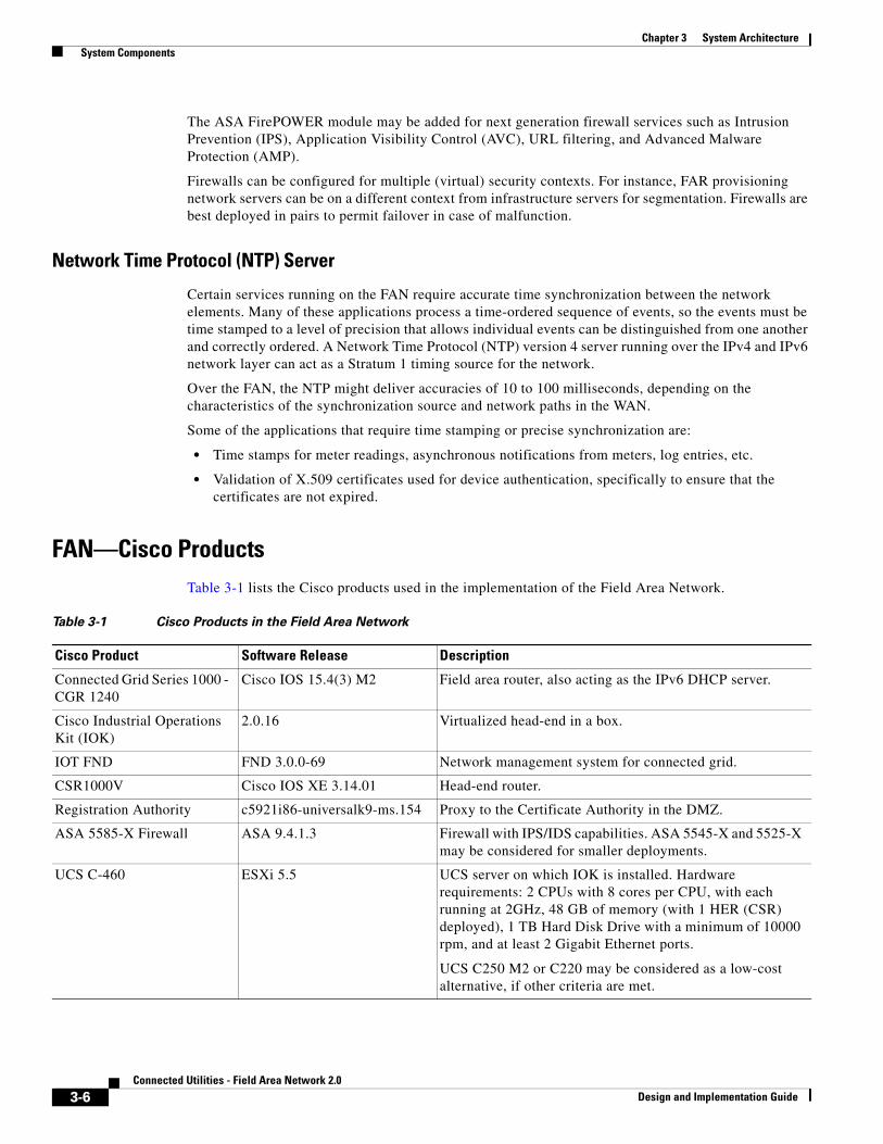
FAN—Cisco ProductsTable 3-1 lists the Cisco products used in the implementation of the Field Area Network.
Table 3-1 Cisco Products in the Field Area Network
Cisco Product Software Release Description
Connected Grid Series 1000 - CGR 1240
Cisco IOS 15.4(3) M2 Field area router, also acting as the IPv6 DHCP server.
Cisco Industrial Operations Kit (IOK)
2.0.16 Virtualized head-end in a box.
IOT FND FND 3.0.0-69 Network management system for connected grid.
CSR1000V Cisco IOS XE 3.14.01 Head-end router.
Registration Authority c5921i86-universalk9-ms.154 Proxy to the Certificate Authority in the DMZ.
ASA 5585-X Firewall ASA 9.4.1.3 Firewall with IPS/IDS capabilities. ASA 5545-X and 5525-X may be considered for smaller deployments.
UCS C-460 ESXi 5.5 UCS server on which IOK is installed. Hardware requirements: 2 CPUs with 8 cores per CPU, with each running at 2GHz, 48 GB of memory (with 1 HER (CSR) deployed), 1 TB Hard Disk Drive with a minimum of 10000 rpm, and at least 2 Gigabit Ethernet ports.
UCS C250 M2 or C220 may be considered as a low-cost alternative, if other criteria are met.
3-6Connected Utilities - Field Area Network 2.0
Design and Implementation Guide
Chapter 3 System Architecture System Design Specifications
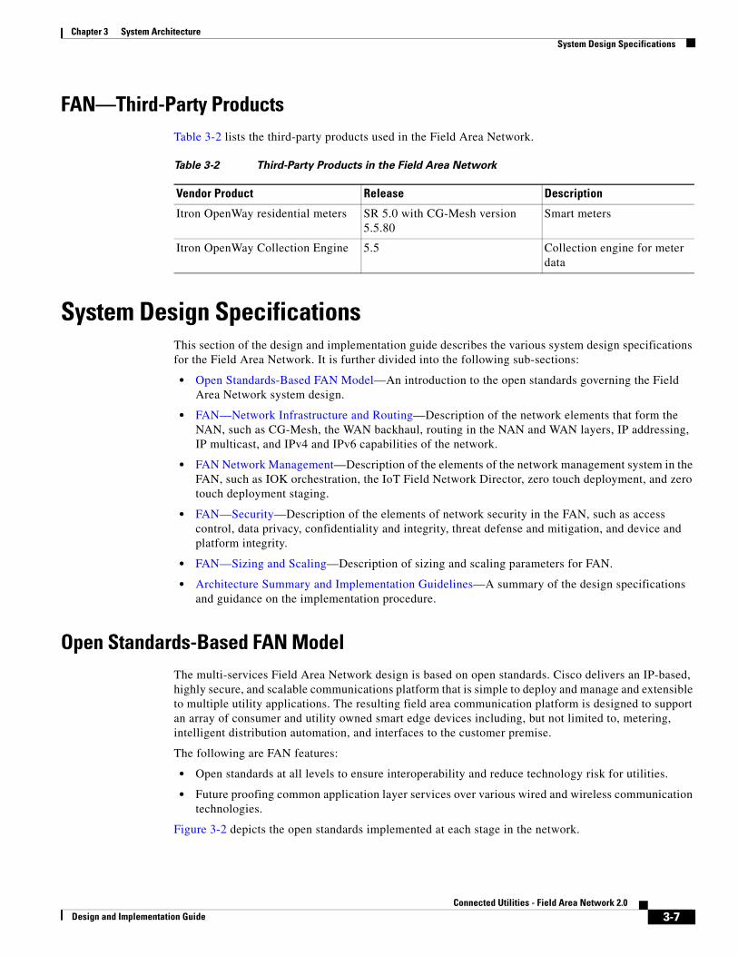
FAN—Third-Party ProductsTable 3-2 lists the third-party products used in the Field Area Network.
System Design SpecificationsThis section of the design and implementation guide describes the various system design specifications for the Field Area Network. It is further divided into the following sub-sections:
• Open Standards-Based FAN Model—An introduction to the open standards governing the Field Area Network system design.
• FAN—Network Infrastructure and Routing—Description of the network elements that form the NAN, such as CG-Mesh, the WAN backhaul, routing in the NAN and WAN layers, IP addressing, IP multicast, and IPv4 and IPv6 capabilities of the network.
• FAN Network Management—Description of the elements of the network management system in the FAN, such as IOK orchestration, the IoT Field Network Director, zero touch deployment, and zero touch deployment staging.
• FAN—Security—Description of the elements of network security in the FAN, such as access control, data privacy, confidentiality and integrity, threat defense and mitigation, and device and platform integrity.
• FAN—Sizing and Scaling—Description of sizing and scaling parameters for FAN.
• Architecture Summary and Implementation Guidelines—A summary of the design specifications and guidance on the implementation procedure.
Open Standards-Based FAN ModelThe multi-services Field Area Network design is based on open standards. Cisco delivers an IP-based, highly secure, and scalable communications platform that is simple to deploy and manage and extensible to multiple utility applications. The resulting field area communication platform is designed to support an array of consumer and utility owned smart edge devices including, but not limited to, metering, intelligent distribution automation, and interfaces to the customer premise.
The following are FAN features:
• Open standards at all levels to ensure interoperability and reduce technology risk for utilities.
• Future proofing common application layer services over various wired and wireless communication technologies.
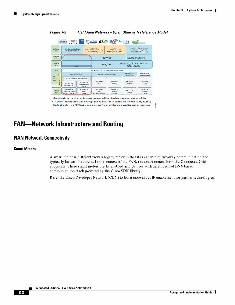
Figure 3-2 depicts the open standards implemented at each stage in the network.
Table 3-2 Third-Party Products in the Field Area Network
Vendor Product Release Description
Itron OpenWay residential meters SR 5.0 with CG-Mesh version 5.5.80
Smart meters
Itron OpenWay Collection Engine 5.5 Collection engine for meter data
3-7Connected Utilities - Field Area Network 2.0
Design and Implementation Guide
Chapter 3 System Architecture System Design Specifications
Figure 3-2 Field Area Network—Open Standards Reference Model
FAN—Network Infrastructure and Routing
NAN Network Connectivity
Smart Meters
A smart meter is different from a legacy meter in that it is capable of two-way communication and typically has an IP address. In the context of the FAN, the smart meters form the Connected Grid endpoints. These smart meters are IP-enabled grid devices with an embedded IPv6-based communication stack powered by the Cisco SDK library.
Refer the Cisco Developer Network (CDN) to learn more about IP enablement for partner technologies.
3756
10
3-8Connected Utilities - Field Area Network 2.0
Design and Implementation Guide
Chapter 3 System Architecture System Design Specifications
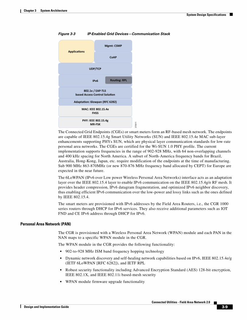
Figure 3-3 IP-Enabled Grid Devices—Communication Stack
The Connected Grid Endpoints (CGEs) or smart meters form an RF-based mesh network. The endpoints are capable of IEEE 802.15.4g Smart Utility Networks (SUN) and IEEE 802.15.4e MAC sub-layer enhancements supporting PHYs SUN, which are physical layer communication standards for low-rate personal area networks. The CGEs are certified for the Wi-SUN 1.0 PHY profile. The current implementation supports frequencies in the range of 902-928 MHz, with 64 non-overlapping channels and 400 kHz spacing for North America. A subset of North-America frequency bands for Brazil, Australia, Hong-Kong, Japan, etc. require modification of the endpoints at the time of manufacturing. Sub 900 MHz 863-870MHz (or new 870-876 MHz frequency band allocated by CEPT) for Europe are expected in the near future.
The 6LoWPAN (IPv6 over Low power Wireless Personal Area Networks) interface acts as an adaptation layer over the IEEE 802.15.4 layer to enable IPv6 communication on the IEEE 802.15.4g/e RF mesh. It provides header compression, IPv6 datagram fragmentation, and optimized IPv6 neighbor discovery, thus enabling efficient IPv6 communication over the low-power and lossy links such as the ones defined by IEEE 802.15.4.
The smart meters are provisioned with IPv6 addresses by the Field Area Routers, i.e., the CGR 1000 series routers through DHCP for IPv6 services. They also receive additional parameters such as IOT FND and CE IPv6 address through DHCP for IPv6.
Personal Area Network (PAN)
The CGR is provisioned with a Wireless Personal Area Network (WPAN) module and each PAN in the NAN maps to a specific WPAN module in the CGR.
The WPAN module in the CGR provides the following functionality:
• 902-to-928 MHz ISM band frequency hopping technology
• Dynamic network discovery and self-healing network capabilities based on IPv6, IEEE 802.15.4e/g (IETF 6LoWPAN [RFC 6282]), and IETF RPL
• Robust security functionality including Advanced Encryption Standard (AES) 128-bit encryption, IEEE 802.1X, and IEEE 802.11i based-mesh security
• WPAN module firmware upgrade functionality
3756
11
Adapta�on: 6lowpan (RFC 6282)
IPv6
UDP/TCP
PHY: IEEE 802.15.4gMR-FSK
MAC: IEEE 802.15.4eFHSS
Rou�ng: RPL
Mgmt: CSMP
CoAP
802.1x / EAP-TLS based Access Control Solu�on
Applica�ons
3-9Connected Utilities - Field Area Network 2.0
Design and Implementation Guide
Chapter 3 System Architecture System Design Specifications
• WPAN module interface statistics and status
The IEEE 802.15.4e/g WPAN module hardware contains the following:
• Micro-controller, an RF transceiver operating in the 902-to-928 MHz ISM band
• Frequency synthesizer
• RF Micro Devices RF6559 front-end module
Layer 3 interfaces on the CGR 1000, such as Ethernet, Wi-Fi, fiber, or cellular must be enabled and properly addressed and must get their directly connected IPv4 and/or IPv6 prefixes advertised through the chosen WAN routing protocol. Route entries must be added on the head-end router and other FARs. Loopback interfaces must be enabled for network management, local applications, and tunnel or routing configuration.
The WPAN module is configured with a PAN ID, which is a 16-bit field, described in the IEEE 802.15.4 specification. It is received and used by all devices grouped in the same PAN. A smart meter is a node in the RPL tree and can only be a part of a single PAN at a time.
Apart from the PAN ID, CGEs or smart meters are configured with a particular SSID, similar to an IEEE 802.11 SSID at the time of manufacturing. This acts as an identifier for the utility network. It represents the network name that is advertised through IEEE 802.15.4e enhanced frames that can pass additional vendor information. The network name is included in the IEEE 802.15.4 Enhanced Beacons using an Information Element. This SSID must be configured on the CGR as well. All IEEE 802.15.4 messages, except IEEE 802.15.4 Enhanced Broadcast and Enhanced Beacon Request (EBR) messages are sent with a destination PAN identical to the source PAN.
A CGR can be configured with dual WPANs for either of the following scenarios:
• Multiple WPANs can operate in the network, each as independent WPAN and independent CG-Mesh. In this configuration, each WPAN forms a separate RPL tree and mesh and each must have a unique IPv6 prefix and Service Set Identifier (SSID).
• A WPAN can also operate in a master-slave configuration. The master WPAN owns the RPL tree and the mesh and all IPv6 and 802.1X traffic flows through the master WPAN from the perspective of the CGR and FND. Conceptually, the slave WPAN acts only as a NIC at the MAC and PHY layer. In that sense, the slave WPAN is attached to the master WPAN.
However, the current solution does not feature dual WPANs. Dual WPANs may be provisioned after appropriate RF planning and considering antenna recommendations.
EBRs allow CGEs to obtain information about neighboring PANs even while joined to a specific PAN. EBR messages contain information elements that provide some information about the transmitting node’s RPL routing metric (that is, METX) and size of the PAN. Routing metric information is included so that nodes can make some determination about how a path to a FAR might improve if the node switches to a different PAN and uses the neighbor as a default route in that new PAN. The PAN network size is used to perform load balancing between PANs and help ensure that a single PAN does not carry an unnecessary burden.
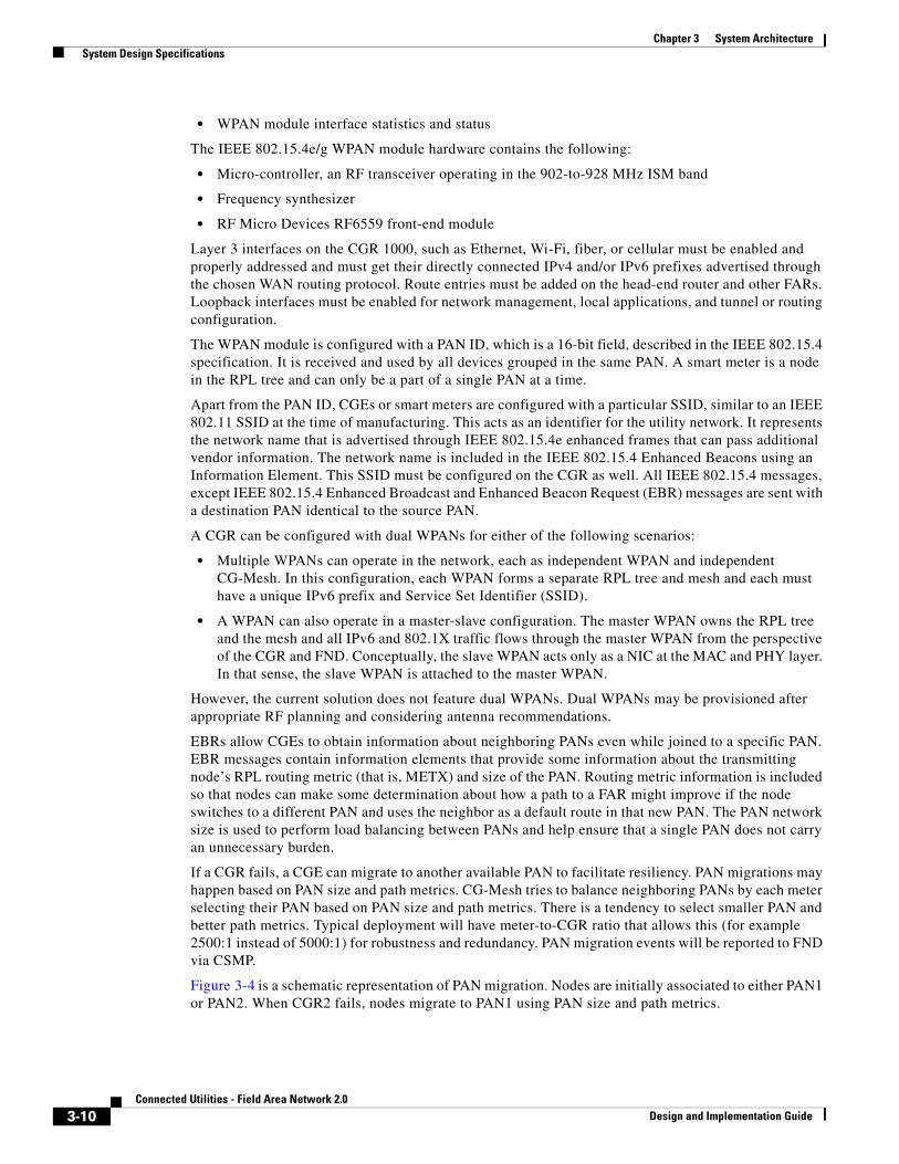
If a CGR fails, a CGE can migrate to another available PAN to facilitate resiliency. PAN migrations may happen based on PAN size and path metrics. CG-Mesh tries to balance neighboring PANs by each meter selecting their PAN based on PAN size and path metrics. There is a tendency to select smaller PAN and better path metrics. Typical deployment will have meter-to-CGR ratio that allows this (for example 2500:1 instead of 5000:1) for robustness and redundancy. PAN migration events will be reported to FND via CSMP.
Figure 3-4 is a schematic representation of PAN migration. Nodes are initially associated to either PAN1 or PAN2. When CGR2 fails, nodes migrate to PAN1 using PAN size and path metrics.
3-10Connected Utilities - Field Area Network 2.0
Design and Implementation Guide
Chapter 3 System Architecture System Design Specifications
Figure 3-4 PAN Migration Following a CGR Failure
CGEs implement standard IPv6 services. The IPv6 layer also uses the mesh interface to forward IPv6 datagrams across other communication modules.
RFC 768 User Datagram Protocol (UDP) is the recommended transport layer over 6LoWPAN.
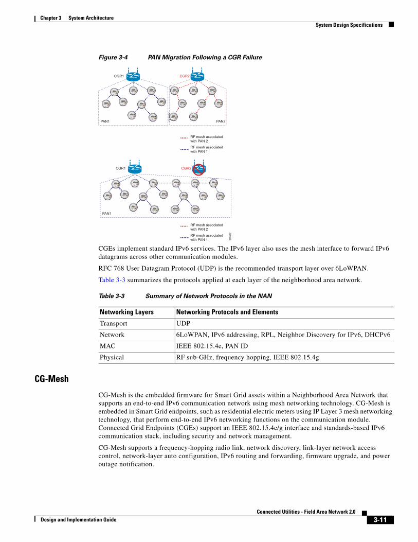
Table 3-3 summarizes the protocols applied at each layer of the neighborhood area network.
CG-Mesh
CG-Mesh is the embedded firmware for Smart Grid assets within a Neighborhood Area Network that supports an end-to-end IPv6 communication network using mesh networking technology. CG-Mesh is embedded in Smart Grid endpoints, such as residential electric meters using IP Layer 3 mesh networking technology, that perform end-to-end IPv6 networking functions on the communication module. Connected Grid Endpoints (CGEs) support an IEEE 802.15.4e/g interface and standards-based IPv6 communication stack, including security and network management.
CG-Mesh supports a frequency-hopping radio link, network discovery, link-layer network access control, network-layer auto configuration, IPv6 routing and forwarding, firmware upgrade, and power outage notification.
3756
12
CGR1 CGR2
PAN1 PAN2
RF mesh associatedwith PAN 2
RF mesh associatedwith PAN 1
CGR1 CGR2
PAN1
RF mesh associatedwith PAN 2
RF mesh associatedwith PAN 1
Table 3-3 Summary of Network Protocols in the NAN
Networking Layers Networking Protocols and Elements
Transport UDP
Network 6LoWPAN, IPv6 addressing, RPL, Neighbor Discovery for IPv6, DHCPv6
MAC IEEE 802.15.4e, PAN ID
Physical RF sub-GHz, frequency hopping, IEEE 802.15.4g
3-11Connected Utilities - Field Area Network 2.0
Design and Implementation Guide
Chapter 3 System Architecture System Design Specifications
CG-Mesh Deployment
The following points summarize the deployment of the CG-Mesh:
• The meter manufacturer loads the firmware to the communication module of the meters and performs customer specific configuration. Meters are factory-configured for EUI64 (MAC), SSID, regional compliance factors, certificates such as unique meter certificate, AAA CA certificate, and NMS certificate.
• CG-Mesh nodes can become manageable via CSMP (CoAP Simple Management Protocol) once they are registered with FND.
• The CGR or the Field Area Router must also be registered with the FND.
• The CGR is configured by the FND. CG-Mesh related configuration should not be manipulated directly through the CGR CLI.
CG-Mesh Formation
When meters join the network on booting for the first time, the process is referred to as cold boot. A cold boot is when the meter has not yet been authenticated because it is the first time the meter is joining the network or the meter key has expired.
The process is referred to as warm boot when the meter has a working key, in which case authentication has already been established and the meter joins the mesh quickly.
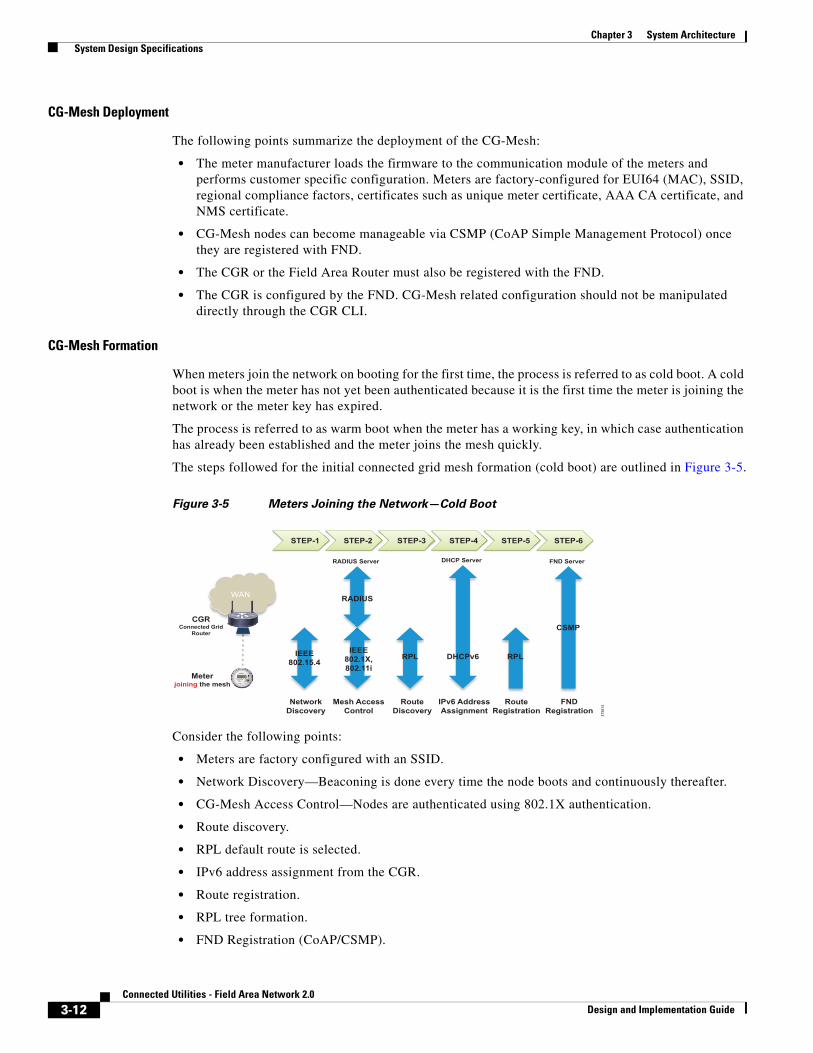
The steps followed for the initial connected grid mesh formation (cold boot) are outlined in Figure 3-5.
Figure 3-5 Meters Joining the Network—Cold Boot
Consider the following points:
• Meters are factory configured with an SSID.
• Network Discovery—Beaconing is done every time the node boots and continuously thereafter.
• CG-Mesh Access Control—Nodes are authenticated using 802.1X authentication.
• Route discovery.
• RPL default route is selected.
• IPv6 address assignment from the CGR.
• Route registration.
• RPL tree formation.
• FND Registration (CoAP/CSMP).
WAN
CGRConnected Grid
Router
Meterjoining the mesh
Network Discovery
Mesh Access Control
Route Discovery
IEEE 802.15.4
IEEE 802.1X, 802.11i
RPL DHCPv6
IPv6 Address Assignment
RPL
Route Registration
CSMP
FND Registration
RADIUS
STEP-1 STEP-2 STEP-3 STEP-4 STEP-5 STEP-6
RADIUS Server DHCP Server FND Server
3756
13
3-12Connected Utilities - Field Area Network 2.0
Design and Implementation Guide
Chapter 3 System Architecture System Design Specifications
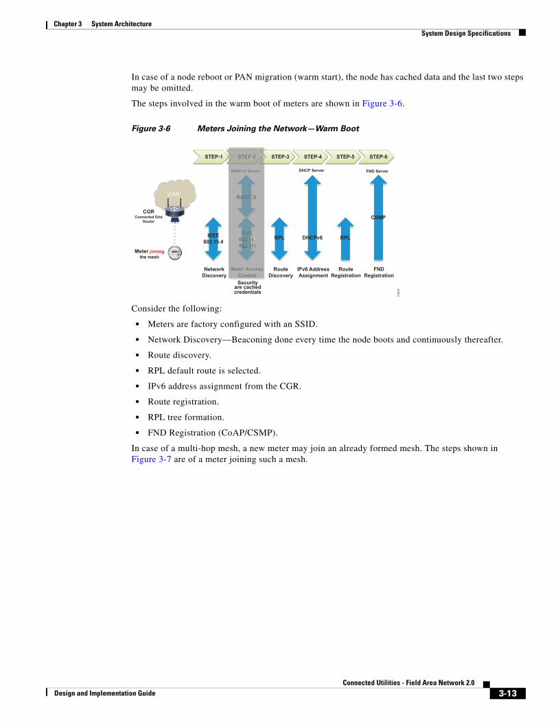
In case of a node reboot or PAN migration (warm start), the node has cached data and the last two steps may be omitted.
The steps involved in the warm boot of meters are shown in Figure 3-6.
Figure 3-6 Meters Joining the Network—Warm Boot
Consider the following:
• Meters are factory configured with an SSID.
• Network Discovery—Beaconing done every time the node boots and continuously thereafter.
• Route discovery.
• RPL default route is selected.
• IPv6 address assignment from the CGR.
• Route registration.
• RPL tree formation.
• FND Registration (CoAP/CSMP).
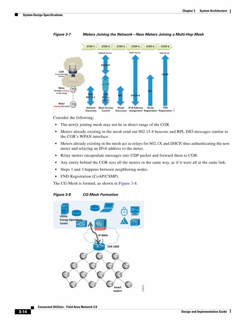
In case of a multi-hop mesh, a new meter may join an already formed mesh. The steps shown in Figure 3-7 are of a meter joining such a mesh.
STEP-1 STEP-2 STEP-3 STEP-4 STEP-5 STEP-6
WAN
CGRConnected Grid
Router
Network Discovery
Mesh Access Control
Route Discovery
IEEE 802.15.4
IEEE 802.1x, 802.11i
RPL DHCPv6
IPv6 Address Assignment
RPL
Route Registration
CSMP
FND Registration
RADIUS
RADIUS Server DHCP Server FND Server
STEP-2
Mesh AccessControl
II EEEE8002. x1 ,8002.111i
RAADIUUS
RADIUS Serverr r
Security
credentials are cached
Meter joiningthe mesh
3756
14
3-13Connected Utilities - Field Area Network 2.0
Design and Implementation Guide
Chapter 3 System Architecture System Design Specifications
Figure 3-7 Meters Joining the Network—New Meters Joining a Multi-Hop Mesh
Consider the following:
• The newly joining mesh may not be in direct range of the CGR.
• Meters already existing in the mesh send out 802.15.4 beacons and RPL DIO messages similar to the CGR’s WPAN interface.
• Meters already existing in the mesh act as relays for 802.1X and DHCP, thus authenticating the new meter and relaying an IPv6 address to the meter.
• Relay meters encapsulate messages into UDP packet and forward them to CGR.
• Any entity behind the CGR sees all the meters in the same way, as if it were all at the same link.
• Steps 1 and 3 happens between neighboring nodes.
• FND Registration (CoAP/CSMP).
The CG-Mesh is formed, as shown in Figure 3-8.
Figure 3-8 CG-Mesh Formation
PAN wireless mesh
WAN
CGRConnected Grid
Router
MeterAlready existing
in the mesh
Network Discovery
Mesh Access Control
Route Discovery
IEEE 802.15.4 RPL
IPv6 Address Assignment
RPL
Route Registration
CSMP
FND Registration
RADIUS
RADIUS Server DHCP Server FND Server
Pv6 Addre
DHCPv6
esh Acce
IEEE 802.1x, 802.11i
over UDP
Meterjoining the mesh
STEP-1 STEP-2 STEP-3 STEP-4 STEP-5 STEP-6
PAP N
3756
15
U�lity Energy Opera�ons Center
IP WAN
CGR 1000
Smart meters 37
5616
3-14Connected Utilities - Field Area Network 2.0
Design and Implementation Guide
Chapter 3 System Architecture System Design Specifications
Frequency Hopping
CGEs implement frequency hopping across 64 channels with 400-kHz spacing in the 902-to-928 MHz ISM band. The frequency hopping protocol maximizes the use of the available spectrum by allowing multiple sender-receiver pairs to communicate simultaneously on different channels. The frequency hopping protocol also mitigates the negative effects of narrowband interferers.
CGEs allow each communication module to follow its own channel-hopping schedule for unicast communication and synchronize with neighboring nodes to periodically listen to the same channel for broadcast communication. This enables all nodes within a CGE PAN to use different parts of the spectrum simultaneously for unicast communication when nodes are not listening for a broadcast message. Using this model, broadcast transmissions can experience higher latency than with unicast transmissions.
When a communication module has a message destined for multiple receivers, it waits until its neighbors are listening on the same channel for a transmission. The size of a broadcast listening window and the period of such listening windows determine how often nodes listen for broadcast messages together rather than listening on their own channels for unicast messages.
CG-Mesh uses the communication module hardware in a way that is compliant with the IEEE 802.15.4e/g MAC/PHY specification. CG-Mesh uses the following PHY parameters:
• Operating Band: 902 to 928 MHz
• Number of Channels: 64
• Channel Spacing: 400 kHz
• Modulation Method: Binary FSK
• 150 kbaud data rate, 75 bit rate due to FEC
• Maximum output Power: 28 dBm
Enhanced Beacon (EB) messages allow communication modules to discover PANs that they can join. CGEs also use EB messages that disseminate useful PAN information to devices that are in the process of joining the PAN. Joining nodes are nodes that have not yet been granted access to the PAN. As such, joining nodes cannot communicate IPv6 datagrams with neighboring devices. The EB message is the only message sent in the clear that can provide useful information to joining nodes. CGRs drive the dissemination process for all PAN-wide information.
Joining devices also use the RSSI (Received Signal Strength Indication) value of the received EB message to determine if a neighbor is likely to provide a good link. The transceiver hardware provides the RSSI value. Neighbors that have an RSSI value below the minimum threshold during the course of receiving EB messages are not considered for PAN access requests.
CGEs support the following performance-enhancing parameters:
• Network discovery time—To assist field installations, CGEs support mechanisms that allow a node to determine whether or not it has good connectivity to a valid mesh network.
• Network formation time—To assist field installations, CGEs use mechanisms that allow up to 5,000 nodes in a single WPAN to go through the complete network-discovery, access-control, network configuration, route formation, and application registration process.
• Network restoration time—The mechanism that aids the rerouting of traffic during a link failure.
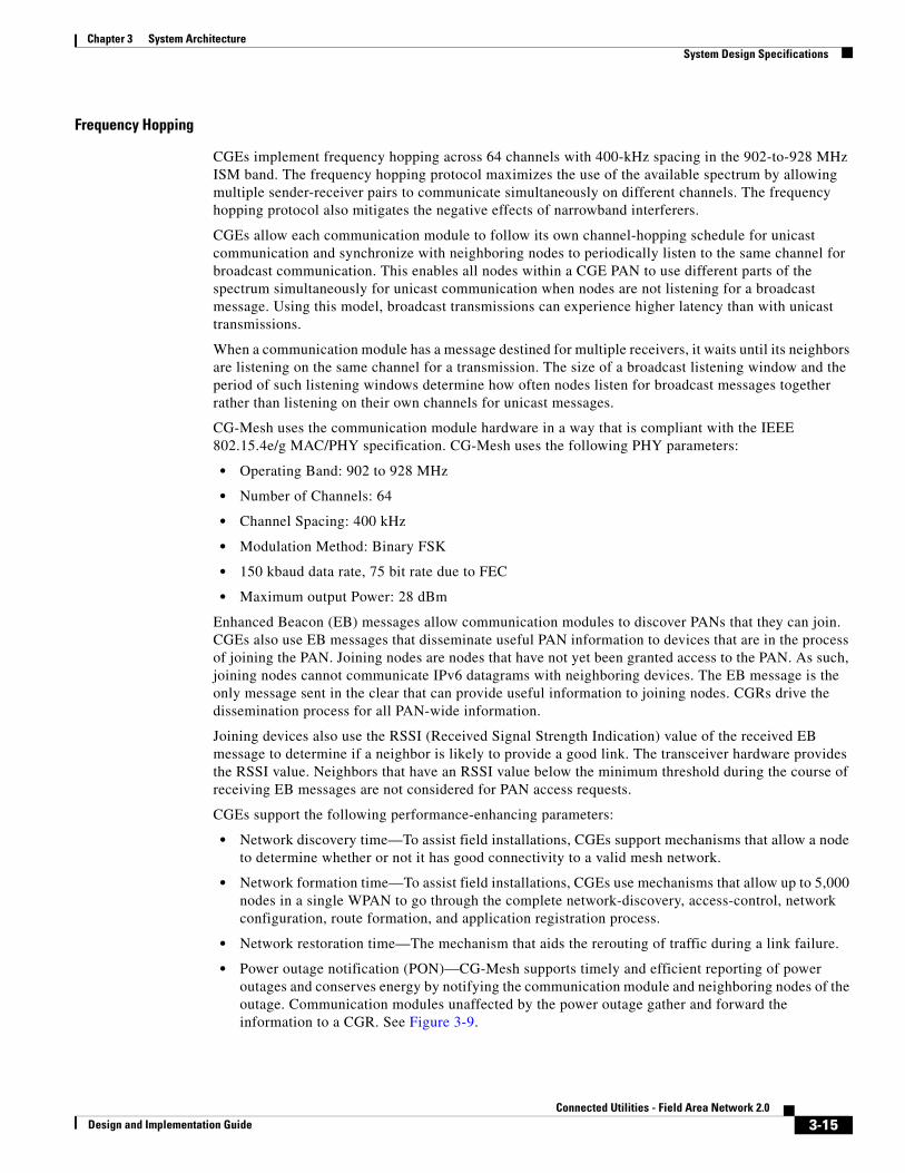
• Power outage notification (PON)—CG-Mesh supports timely and efficient reporting of power outages and conserves energy by notifying the communication module and neighboring nodes of the outage. Communication modules unaffected by the power outage gather and forward the information to a CGR. See Figure 3-9.
3-15Connected Utilities - Field Area Network 2.0
Design and Implementation Guide
Chapter 3 System Architecture System Design Specifications
Figure 3-9 Power Outage Notification (PON)
NAN Routing
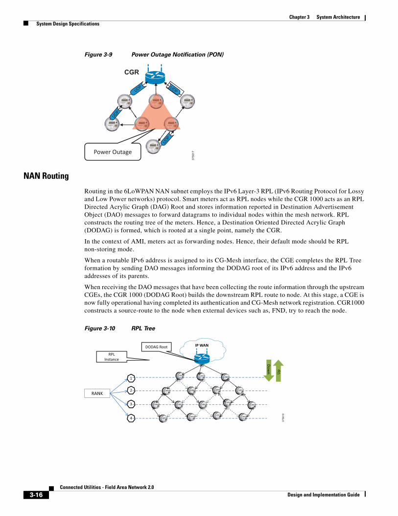
Routing in the 6LoWPAN NAN subnet employs the IPv6 Layer-3 RPL (IPv6 Routing Protocol for Lossy and Low Power networks) protocol. Smart meters act as RPL nodes while the CGR 1000 acts as an RPL Directed Acrylic Graph (DAG) Root and stores information reported in Destination Advertisement Object (DAO) messages to forward datagrams to individual nodes within the mesh network. RPL constructs the routing tree of the meters. Hence, a Destination Oriented Directed Acrylic Graph (DODAG) is formed, which is rooted at a single point, namely the CGR.
In the context of AMI, meters act as forwarding nodes. Hence, their default mode should be RPL non-storing mode.
When a routable IPv6 address is assigned to its CG-Mesh interface, the CGE completes the RPL Tree formation by sending DAO messages informing the DODAG root of its IPv6 address and the IPv6 addresses of its parents.
When receiving the DAO messages that have been collecting the route information through the upstream CGEs, the CGR 1000 (DODAG Root) builds the downstream RPL route to node. At this stage, a CGE is now fully operational having completed its authentication and CG-Mesh network registration. CGR1000 constructs a source-route to the node when external devices such as, FND, try to reach the node.
Figure 3-10 RPL Tree
CGR
Power Outage
UDP
UDP UDP
UDP
3756
17
IP WAN
RPLInstance
DODAG Root
RANK
1
2
3
4
Up
Down
3756
18
3-16Connected Utilities - Field Area Network 2.0
Design and Implementation Guide
Chapter 3 System Architecture System Design Specifications
IP Addressing
For most FAN deployments, planning for addressing may be initially required. The IPv4 addressing plan must be derived from the utility’s existing scheme, while the IPv6 addressing plan will most likely be new. In all cases, it is assumed that the network will be dual-stack.
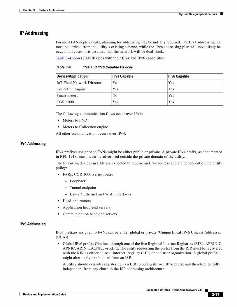
Table 3-4 shows FAN devices with their IPv4 and IPv6 capabilities.
The following communication flows occur over IPv6:
• Meters to FND
• Meters to Collection engine
All other communication occurs over IPv4.
IPv4 Addressing
IPv4 prefixes assigned to FANs might be either public or private. A private IPv4 prefix, as documented in RFC 1918, must never be advertised outside the private domain of the utility.
The following devices in FAN are expected to require an IPv4 address and are dependent on the utility policy:
• FARs: CGR 1000 Series router
– Loopback
– Tunnel endpoint
– Layer 3 Ethernet and Wi-Fi interfaces
• Head-end routers
• Application head-end servers
• Communication head-end servers
IPv6 Addressing
IPv6 prefixes assigned to FANs can be either global or private (Unique Local IPv6 Unicast Addresses (ULA)).
• Global IPv6 prefix: Obtained through one of the five Regional Internet Registries (RIR): AFRINIC, APNIC, ARIN, LACNIC, or RIPE. The entity requesting the prefix from the RIR must be registered with the RIR as either a Local Internet Registry (LIR) or end-user organization. A global prefix might alternately be obtained from an ISP.
A utility should consider registering as a LIR to obtain its own IPv6 prefix and therefore be fully independent from any churn in the ISP addressing architecture.
Table 3-4 IPv4 and IPv6 Capable Devices
Device/Application IPv4 Capable IPv6 Capable
IoT Field Network Director Yes Yes
Collection Engine Yes Yes
Smart meters No Yes
CGR 1000 Yes Yes
3-17Connected Utilities - Field Area Network 2.0
Design and Implementation Guide
Chapter 3 System Architecture System Design Specifications
RIRs define policies regarding allocation of an IPv6 prefix and the prefix size. A RIR prefix allocation is by default ::/32 prefix for a LIR, and ::/48 for an end-user organization. The RIR policies also define how larger or smaller prefixes can be allocated to a LIR and an end-user organization.
A justification, based on the number of sites and hosts, must be given for the non-default allocation. The number of FAN sites and subnets drive the decision to register as a LIR or as an end-user organization and further justify the requests made for prefix allocation and size.
• ULA IPv6 prefix: A unique local address (ULA) IPv6 prefix, documented in RFC 4193, is allowed to be “nearly unique”. It starts with a FC00::/7 value but the following 41 bits, global routing ID, allow an addressing space far greater than the 3-private IPv4 prefixes (10.0.0.0/8, 172.16.0.0/12, 192.168.0.0/16) documented in RFC 1918. The size of the global routing ID effectively produces a pseudo “uniqueness.” Note, however, that there is currently no central registration of ULA prefixes.
The main differences between selecting a global or ULA IPv6 prefix are the following:
• A global prefix requires registration to the RIR either as LIR or an end-user organization, requiring paper work and fees, before getting and justifying an IPv6 prefix allocation. A ULA does not require this registration.
• Filtering at the border of the utility routing domain.
– A ULA IPv6 prefix must NEVER be advertised to the Internet routing table.
– A global IPv6 prefix or portions of its address space might be advertised to the Internet routing table and incoming traffic MUST be properly filtered to block any undesirable traffic.
• Internet access: A ULA-based addressing architecture requires the IPv6-to-IPv6 Network Prefix Translation (IPv6 NPT, RFC 6296) device(s) to be located at the Internet border. Remote workforce management use cases might require Internet access, such as third-party technicians connecting to their corporate network from a FAN site, an FND operator using the Google map features, etc. For web access, web proxies can be a solution.
Once an IPv6 prefix has been allocated for the FAN, a hierarchy numbering the regions, districts, sites, subnets, and devices must be properly structured. IPv6 addressing is classless, but the 128-bit address can be split between a routing prefix, upper 64 bits, the Interface Identifier (IID), and the lower 64 bits. A hierarchical structure eases the configuration of route summarization and filtering.
3-18Connected Utilities - Field Area Network 2.0
Design and Implementation Guide
Chapter 3 System Architecture System Design Specifications
IPv6 Data Flow
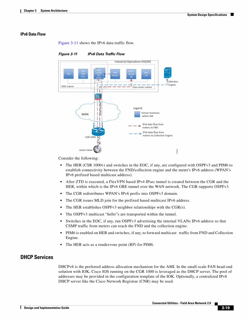
Figure 3-11 shows the IPv6 data traffic flow.
Figure 3-11 IPv6 Data Traffic Flow
Consider the following:
• The HER (CSR 1000v) and switches in the EOC, if any, are configured with OSPFv3 and PIM6 to establish connectivity between the FND/collection engine and the meter's IPv6 address (WPAN’s IPv6 prefixed based multicast address).
• After ZTD is executed, a FlexVPN based IPv4 IPsec tunnel is created between the CGR and the HER, within which is the IPv6 GRE tunnel over the WAN network. The CGR supports OSPFv3.
• The CGR redistributes WPAN’s IPv6 prefix into OSPFv3 domain.
• The CGR issues MLD join for the prefixed based multicast IPv6 address.
• The HER establishes OSPFv3 neighbor relationships with the CGR(s).
• The OSPFv3 multicast “hello”s are transported within the tunnel.
• Switches in the EOC, if any, run OSPFv3 advertising the internal VLANs IPv6 address so that CSMP traffic from meters can reach the FND and the collection engine.
• PIM6 is enabled on HER and switches, if any, to forward multicast traffic from FND and Collection Engine.
• The HER acts as a rendezvous point (RP) for PIM6.
DHCP Services
DHCPv6 is the preferred address allocation mechanism for the AMI. In the small-scale FAN head-end solution with IOK, Cisco IOS running on the CGR 1000 is leveraged as the DHCP server. The pool of addresses may be provided in the configuration template of the IOK. Optionally, a centralized IPv6 DHCP server like the Cisco Network Registrar (CNR) may be used.
3756
19
HER cluster
CSR 1000v
TPS RA ESR
5921
HERHER cluster
CSR 1000v
Free Radius
FND + Oracle
DB
DMZ subnet Data center subnet
IPSe
c tu
nnel
WAN
CGR 1000
Legend Virtual machines within IOK
RSA CA
smart meter
Industrial Opera�ons Kit(IOK)
Collec�on Engine
IPv6 data flow from meters to FND
IPv6 data flow from meters to Collec�on Engine
3-19Connected Utilities - Field Area Network 2.0
Design and Implementation Guide
Chapter 3 System Architecture System Design Specifications
CGEs implement a DHCPv6 client for IPv6 address auto-configuration. CG-Mesh uses the DHCPv6 Rapid Commit option to reduce the traffic to only “Solicit” and “Reply” messages; therefore the DHCPv6 server (namely the CGR 1000) must support this option.
CGEs implement a DHCPv6 client, while the CGR acts as a DHCPv6 server. A joining node might not be within range of a CGR and must use a neighboring communication module to make DHCPv6 requests. No DHCPv6 server address needs to be configured on a CGE.
The Cisco IOS on the CGR acts as a DHCP server and accepts address assignment requests and renewals and assigns the addresses from predefined groups of addresses contained within DHCP address pools.
In IPv6 networking, prefix delegation is used to assign a network address prefix to a user site such as a PAN, by configuring the CGR with the prefix to be used for each PAN.
Each 6LoWPAN subnet gets assigned an IPv6 multicast group compliant with the unicast-prefix-based multicast address (RFC 3306). For instance, a PAN rooted at the IPv6 address of 2001:dead:beef:240::/64 has a corresponding multicast address of ff38:0040:2001:dead:beef:240::1.
DHCP services of the IOK are used to provide IP addresses to the IOT FND and other virtual machines IOK.
The user should provide the IPv6 prefix for each PAN during ZTD staging by the IOK.
IP Unicast Forwarding
CGEs or smart meters implement a route-over architecture where forwarding occurs at the network layer. CGEs examine every IPv6 datagram that they receive and determine the next-hop destination based on information contained in the IPv6 header. CGEs do not use any information from the link-layer header to perform next-hop determination.
CGEs implement the options for carrying RPL information in data plane datagrams. The routing header allows a node to specify each hop that a datagram must follow to reach its destination.
The CGE communication stack offers four priority queues for QoS and supports differentiated classes of service when forwarding IPv6 datagrams to manage interactions between different application traffic flows as well as control-plane traffic. CGEs implement a strict-priority queuing policy, where higher-priority traffic always takes priority over lower-priority traffic.
The traffic on CGEs is marked by the vendor implementation (configuration functionality is not available). If required, traffic can be re-marked on the CGR.
IP Multicast
IPv6 multicast is required between the FND or Collection Engine (head-end system) and the CG-Mesh endpoints when performing the following:
• Software upgrades of the endpoints by the FND
• Demand reset messages from the Collection Engine
• Demand response messages from the Collection Engine
• Targeted applications pings (a group of meters on a given feeder, for example) by the FND
• Messaging a group of meters with the same read time/cycle by the collection engine
There is no IPv6 multicast requirement between the FND and the CGR 1000 Series router when performing a Cisco IOS software upgrade.
3-20Connected Utilities - Field Area Network 2.0
Design and Implementation Guide
Chapter 3 System Architecture System Design Specifications
PIM is the protocol of choice for multicast traffic in the Field Area Network. The PIM-SSM is a data delivery model that best supports one-to-many broadcast applications. PIM-SSM builds trees that are rooted in just one source, offering a more secure and scalable model for a limited amount of applications (mostly broadcasting of content). In SSM, an IP datagram is transmitted by an IP unicast source S to an SSM destination address G, which is the multicast group IP address, and receivers can receive this datagram by subscribing to channel (S,G).
This is the ideal model since the smart meters or CGEs are not capable of IPv6 multicast.
Thus, each 6LoWPAN subnet associated with the CGR acts as a multicast group compliant with the unicast-prefix-based multicast address as per RFC 3306, as mentioned earlier. For instance, a PAN rooted at the IPv6 address of 2001:dead:beef:240::/64 has a corresponding multicast address of ff38:0040:2001:dead:beef:240::1.
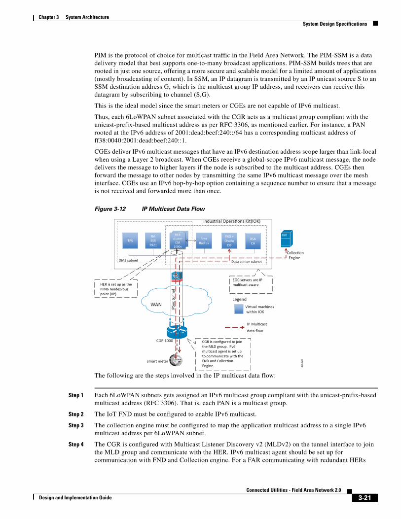
CGEs deliver IPv6 multicast messages that have an IPv6 destination address scope larger than link-local when using a Layer 2 broadcast. When CGEs receive a global-scope IPv6 multicast message, the node delivers the message to higher layers if the node is subscribed to the multicast address. CGEs then forward the message to other nodes by transmitting the same IPv6 multicast message over the mesh interface. CGEs use an IPv6 hop-by-hop option containing a sequence number to ensure that a message is not received and forwarded more than once.
Figure 3-12 IP Multicast Data Flow
The following are the steps involved in the IP multicast data flow:
Step 1 Each 6LoWPAN subnets gets assigned an IPv6 multicast group compliant with the unicast-prefix-based multicast address (RFC 3306). That is, each PAN is a multicast group.
Step 2 The IoT FND must be configured to enable IPv6 multicast.
Step 3 The collection engine must be configured to map the application multicast address to a single IPv6 multicast address per 6LoWPAN subnet.
Step 4 The CGR is configured with Multicast Listener Discovery v2 (MLDv2) on the tunnel interface to join the MLD group and communicate with the HER. IPv6 multicast agent should be set up for communication with FND and Collection engine. For a FAR communicating with redundant HERs
3756
20
HER cluster
CSR 1000v
TPS RA ESR
5921
HERHER cluster
CSR 1000v
Free Radius
FND + Oracle
DB
DMZ subnet Data center subnet
IPSe
c tu
nnel
WAN
CGR 1000
Legend Virtual machines within IOK
RSA CA
smart meter
Industrial Opera�ons Kit(IOK)
Collec�on Engine
CGR is configured to join the MLD group. IPv6 mul�cast agent is set up to communicate with the FND and Collec�on Engine.
HER is set up as the PIM6 rendezvous point (RP)
EOC servers are IP mul�cast aware
IP Mul�cast
data flow
3-21Connected Utilities - Field Area Network 2.0
Design and Implementation Guide
Chapter 3 System Architecture System Design Specifications
within an IOK, the MLDv2 join has to be configured on a loopback interface instead of the GRE tunnel interface. The FAR is then configured with feature PIM6 that enables the active tunnel to listen to the multicast traffic, thus making the FAR act as a PIM6 router. For this particular solution with IOK, the second option is preferred, namely, the MLDv2 join is configured on the loopback interface.
Step 5 Each HER is configured with PIM6 SSM, forwarding the appropriate multicast traffic to the unicast-prefix-based multicast address of the CGR 1000.
Step 6 IoT FND and Collection Engine are the sources of multicast traffic. FND sends a message to the appropriate IPv6 address to target a PAN.
Step 7 The Layer 2 switch in the EOC, if any, must have MLD snooping enabled.
Step 8 The CSR, which is the head-end router, acts as the RP for PIM6 sparse mode. The multicast traffic is forwarded towards the CGR.
Step 9 The multicast traffic is encapsulated and transmitted through the IPsec tunnel.
Step 10 The CGR 1000 receives the IPv6 multicast traffic and forwards it to the meters as a Layer 2 broadcast over the CG mesh. The individual meters can forward the Layer 3 multicast packets after they are mapped to a Layer 2 broadcast.
WAN Backhaul and Routing
The WAN tier connects the Neighborhood Area Network with the Energy Operations Center. The following are some considerations while choosing the technology for the WAN backhaul and its routing protocols:
• Scalability evaluation—The WAN must cater to the aggregation routers located in the EOC and the connected grid end-points in the NAN, and to support the multitude of IP tunnels between them. Dual tunnel configuration should be accounted for, to support resiliency.
• Redundancy and high availability as per Service Level Agreements (SLAs).
• Dual stack routing protocols supported by Cisco IOS, such as MP-BGP, OSPFv3, RIPv2/RIPng, EIGRP, static routes, and IKEv2 prefix injection from FlexVPN.
• Leverage existing WAN infrastructure connecting to the EOC.
• Topology considerations such as hub and spoke configurations.
• Static versus dynamic routing.
• Ease of configuration.
• Convergence time when losing connectivity with the head-end router or the Cisco 1000 Series CGR.
• Latency and bandwidth requirements depending on traffic flow patterns.
For the validation of this solution, Ethernet for the WAN backhaul is considered and OSPFv3 is the routing protocol that is provisioned by IOK during ZTD staging. Open Shortest Path First version 3 (OSPFv3) is an IPv4 and IPv6 link-state routing protocol that supports IPv6 and IPv4 unicast address families (AFs).
Note Changing the routing protocol after pre-ZTD configuration by the IOK is not a recommended practice.
The Field Area Router, namely the CGR 1000 Series Router allows redistribution of the RPL routes including the WPAN prefix as well as the external RPL.
3-22Connected Utilities - Field Area Network 2.0
Design and Implementation Guide
Chapter 3 System Architecture System Design Specifications
Before redistributing RPL in OSPFv3, OSPFv3 must be configured on the uplink tunnel interface. This is orchestrated by the IOK as a part of the ZTD staging process.
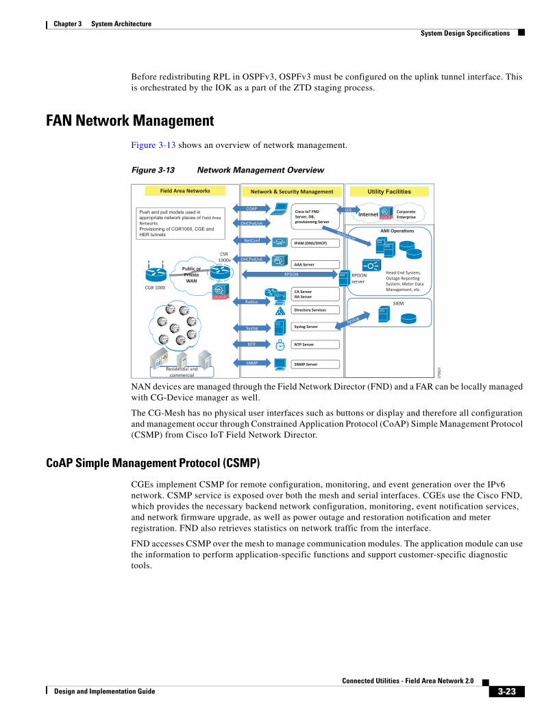
FAN Network ManagementFigure 3-13 shows an overview of network management.
Figure 3-13 Network Management Overview
NAN devices are managed through the Field Network Director (FND) and a FAR can be locally managed with CG-Device manager as well.
The CG-Mesh has no physical user interfaces such as buttons or display and therefore all configuration and management occur through Constrained Application Protocol (CoAP) Simple Management Protocol (CSMP) from Cisco IoT Field Network Director.
CoAP Simple Management Protocol (CSMP)
CGEs implement CSMP for remote configuration, monitoring, and event generation over the IPv6 network. CSMP service is exposed over both the mesh and serial interfaces. CGEs use the Cisco FND, which provides the necessary backend network configuration, monitoring, event notification services, and network firmware upgrade, as well as power outage and restoration notification and meter registration. FND also retrieves statistics on network traffic from the interface.
FND accesses CSMP over the mesh to manage communication modules. The application module can use the information to perform application-specific functions and support customer-specific diagnostic tools.
3756
21
Corporate Enterprise
Head-End System, Outage Repor�ng System, Meter Data Management, etc.
Internet
AMI Opera�ons
CSR 1000v
CGR 1000
RPDON
server
Residen�al and commercial
Public or Private WAN
Push and pull models used in appropriate network places of Field Area Networks Provisioning of CGR1000, CGE and HER tunnels
Field Area Networks Network & Security Management
Syslog Server
NTP Server
SNMP Server
Cisco IoT FND Server, DB, provisioning Server
IPAM (DNS/DHCP)
AAA Server
CA Server RA Server
Directory Services
COAP
DHCPv4/v6
Syslog
SNMP
NTP
Radius
GIS
NetConf
Utility Facilities
SIEM
RPDON
Residdeeeeeeeeeeeeeeeeeeeeeennnnnnnnnnnnnnnnnnnnnnnnnnnnnnnnnnnnnnnnnnnnnnnnnnnnnnnnnnnnn�����������������������������������������������������������������������al and
Northbound API
Syslog
DHCPv4/v6
3-23Connected Utilities - Field Area Network 2.0
Design and Implementation Guide
Chapter 3 System Architecture System Design Specifications
IOK Orchestration
The orchestrator of the IOK performs the following tasks, which can be managed from its web-portal:
• Monitors VM status and provides VM restart functionality.
• Provides license import capability for HER, Certificate Authority and FND.
• Displays system topology with IP information.
• Display user XML configuration file utilized for deployment.
• Tracks and displays event log.
• Provides IOK system backup and restore.
• Provides IOK upgrade with patch file.
• Facilitates the deployment of the CGR 1000 routers. This is also referred to as pre-ZTD configuration or ZTD staging.
Cisco IoT Field Network Director (FND)
The Cisco IoT Field Network Director (formerly called Connected Grid-Network Management System (CG-NMS)) is a software platform that manages network and security infrastructure for multi-service Connected Grid networks and is a part of the Cisco Industrial Operations Kit.
The following are the main components of the FND:
• FND Application Server—This is the core of field area deployments. It runs on a Red Hat Enterprise Linux server and allows administrators to control different aspects of the FND deployment using its browser-based graphical user interface. FND High Availability deployments include two or more FND servers connected to a load balancer.
• FND Database—This Oracle database stores all information managed by the FND solution, including all metrics received from the meters and all device properties such as firmware images, configuration templates, logs, event information, etc.
• Software Security Module (SSM)—This used for signing CSMP messages sent to meters.This is similar to the Hardware Security Module (HSM) used in large AMI deployments.
• TPS Proxy—Allows FARs to communicate with FND when they first start up in the field. After FND provisions tunnels between the FARs and HERs, the FARs communicate with FND directly.
The FND is responsible for the full life cycle network management tasks: fault management, configuration management, accounting management, performance management, security management (FCAPS). FND uses the CoAP Simple Management Protocol (CSMP) for remote configuration, monitoring, and event generation over the IPv6 network.
The following are some of the features and capabilities of the FND:
• Configuration Management—Cisco FND facilitates configuration of large numbers of Cisco CGRs. They can be bulk-configured by placing them into configuration groups, editing settings in a configuration template, and then pushing the configuration to all devices in the group.
• Device and Event Monitoring—Cisco FND displays easy-to-read tabular views of extensive information generated by devices, allowing monitoring the network for errors.
• Status Information—The following parameters are available from the CGEs through CSMP on FND:
– Identification
– UTC time in seconds
3-24Connected Utilities - Field Area Network 2.0
Design and Implementation Guide
Chapter 3 System Architecture System Design Specifications
– IEEE 802.15.4 link
– 6LoWPAN link
– Network interface (for both serial and mesh interface)
– RPL routes
– CG-Mesh firmware
Cisco FND also provides integrated Geographic Information System (GIS) map-based visualization of FAN devices such as routers and smart meters. FND can be used to create CGR-specific work orders that include the required certificates to access the router.
• Firmware Management—Cisco FND serves as a repository for Cisco CGR and meter firmware images. Cisco FND can be used to upgrade the firmware running on groups of devices by loading the firmware image file onto the Cisco FND server and then uploading the image to the devices in the group. Once uploaded, FND can be used to install the firmware image directly on the devices.
• Zero Touch Deployment—This ease-of-use feature automatically registers (enrolls) and distributes X.509 certificates and provisioning information over secure connections within a connected grid network.
• ODM File Upload and Hash Compatibility—Operational Data Model (ODM) files format commands that execute on Cisco IOS routers. FND uses the formatted output for periodic metrics collection, router version information, battery information, reading the hypervisor (virtual machine monitor) version, GPS information, etc. ODM file hash compatibility and upload are performed while requesting a registration, during periodic inventory updates, or during the tunnel provisioning process.
• Tunnel Provisioning Between Head-end Routers and FARs—Protects data exchanged between HERs and Cisco CGRs and prevents unauthorized access to Cisco CGRs to provide secure communication between devices. Cisco FND can execute CLI commands to provision secure tunnels between Cisco CGRs and HERs. FND can be used to bulk-configure tunnel provisioning using groups.
• IPv6 RPL Tree Polling—A node in the IPv6 Routing Protocol for Low power and Lossy Networks (RPL) tree discovers its neighbors and establishes routes using ICMPv6 message exchanges. RPL manages routes based on the relative position of the meter to the CGR that is the root of the routing tree. RPL tree polling is available through the mesh nodes and CGR periodic updates. The RPL tree represents the mesh topology, which is useful for troubleshooting. For example, the hop count information received from the RPL tree can determine the use of unicast or multicast for the firmware download process. FND maintains a periodically updated snapshot of the RPL tree.
• Dual PHY Support—FND can communicate with devices that support Dual PHY (RF and PLC) traffic. FND identifies CGRs running Dual PHY, enables configuration to masters and slaves, and collects metrics from masters. FND also manages security keys for Dual PHY CGRs. On the mesh side, FND identifies Dual PHY nodes using unique hardware IDs, enables configuration pushes and firmware updates, and collects metrics, including RF and PLC traffic ratios. However, the current solution only features RF technology in the physical layer.
• Guest OS (GOS) Support—For Cisco IOS CGR1000 devices that support GuestOS, FND allows approved users to manage applications running on the supported operating systems. FND supports all phases of application deployment and displays application status and the hypervisor version running on the device.
• Device Location Tracking—For CGR 1000 devices, FND displays real-time location and device location history.
• Software Security Module (SSM)—This is a low-cost alternative to the Hardware Security Module (HSM) and is used for signing CSMP messages sent to meters.
3-25Connected Utilities - Field Area Network 2.0
Design and Implementation Guide
Chapter 3 System Architecture System Design Specifications
• Diagnostics and Troubleshooting—The FND rule engine infrastructure provides effective monitoring of triage-based troubleshooting. Device troubleshooting runs on-demand device path trace and ping on any CGR, range extender, or meters.
• Power Outage Notifications—CGEs implement a power outage notification service to support timely and efficient reporting of power outages. In the event of a power outage, CGEs perform the necessary functions to conserve energy and notify neighboring nodes of the outage. FARs relay the power outage notification to FND, which then issues push notifications to customers to relate information on the outage.
• Mesh Upgrade Support—Over-the-air software and firmware upgrades to field devices, such as Cisco CGRs and meters.
• Audit Logging—Logs access information for user activity for audit, regulatory compliance, and Security Event and Incident Management (SEIM) integration. This simplifies management and enhances compliance by integrated monitoring, reporting, and troubleshooting capabilities.
• North Bound APIs—Eases integration of existing utility applications such as outage management system (OMS), meter data management (MDM), trouble-ticketing systems, and manager-of-managers.
• Work Orders for Device Manager—Credentialed field technicians can remotely access and update work orders.
• Role-Based Access Controls—Integrates with enterprise security policies and role-based access control for AMI network devices.
• Event and Issue Management—Fault event collection, filtering, and correlation for communication network monitoring. FND supports a variety of fault-event mechanisms for threshold-based rule processing, custom alarm generation, and alarm event processing. Faults display on a color-coded GIS-map view for various endpoints in the utility network. This allows operator-level custom, fault-event generation, processing, and forwarding to various utility applications such as an outage management system. Automatic issue tracking is based on the events collected.
The following are the devices in the solution supported by the FND:
• Cisco 1000 Series Connected Grid Routers
• CG-Mesh endpoints—IPv6 RF-based smart meters
Zero-Touch Deployment Staging by IOK
The Orchestration virtual machine of the IOK facilitates the pre-ZTD configuration (also referred to as Router ZTD staging) of the CGR 1000 series routers with a single click of a button. The Router ZTD Staging pop-up window has provision for single router ZTD, as well as batch ZTD for multiple routers. A user-configured CSV file is given as an input for batch staging.
Following are the steps performed by the IOK for Zero Touch Deployment staging, using the FARs’ router console.
• Configures the following parameters:
– WAN interface
– NTP server
– Name Server
– Device (CGR) IP and routing
3-26Connected Utilities - Field Area Network 2.0
Design and Implementation Guide
Chapter 3 System Architecture System Design Specifications
• Configures PKI parameters—LDevID (Utility’s certificate) trust-points and LDevID certificate enrollment.
• Configures HTTPS—HTTPS server for WSMA (Web Services Management Agent) and HTTPS client for CGNA (Connected Grid Network Agent).
• Configures replace configuration—Configuration requests sent to WSMA can specify action to be performed when an error is encountered. If the action is specified as rollback, then WSMA stops processing at the first error and restores the configuration to the state before the configuration was applied. WSMA makes use of the IOS configuration archive to support this functionality.
• WSMA configuration—WSMA is configured to listen for incoming requests. The configuration WSMA service is used to configure the CGR, the exec WSMA service is used for operations such as configure replace.
• Configures WSMA to be integrated with AAA, to enable FND to use a username and password to access WSMA. The default username is cg-nms-administrator.
• Configures WPAN module on the CGR and allows CG endpoints, such as smart meters, to establish communication.
• Configures CGNA profiles to allow communication with TPS/FND. Profile will be activated once certificates have been enrolled.
• ODM (Operator Data Modeler) configuration—Used to convert CLI command output to XML. Factory configuration contains CLI commands that reference the specific file used by ODM to direct the conversion.
• Imports device information onto NMS (FND) after ZTD Staging completed.
The CGR 1000 series routers that act as the Field Area Routers should be staged in the EOC network within the utility premises and then shipped and deployed in the field.
Zero Touch Deployment (ZTD) by FND
Zero Touch Deployment in the context of the network management system, namely IoT FND refers to provisioning of IP tunnels to facilitate communication between the head-end and the CGR 1000 series routers and registration of the connected grid endpoints.
It must be noted that any communication from the CGR to the data center subnet, must be secure. The VPN tunnel between the CGR and the HER, across the WAN, ensures this. ZTD process entails provisioning of this tunnel. Prior to the establishment of this tunnel, the CGR can only communicate with the devices in the DMZ, namely the TPS and the Registration Authority.
After installing and powering on the CGR 1000, it becomes active in the network and registers its certificate with the Registration Authority by employing the Simple Certificate Enrollment Protocol (SCEP). The Registration Authority (Cisco ESR 5921), functioning as a CA proxy, obtains certificates for the Cisco CGR from the CA. The Cisco CGR then sends a tunnel-provisioning request over HTTPS to the TPS proxy that forwards it to FND. Cisco FND pushes the configuration to create a tunnel between a Cisco CGR and a head-end router.
3-27Connected Utilities - Field Area Network 2.0
Design and Implementation Guide
Chapter 3 System Architecture System Design Specifications
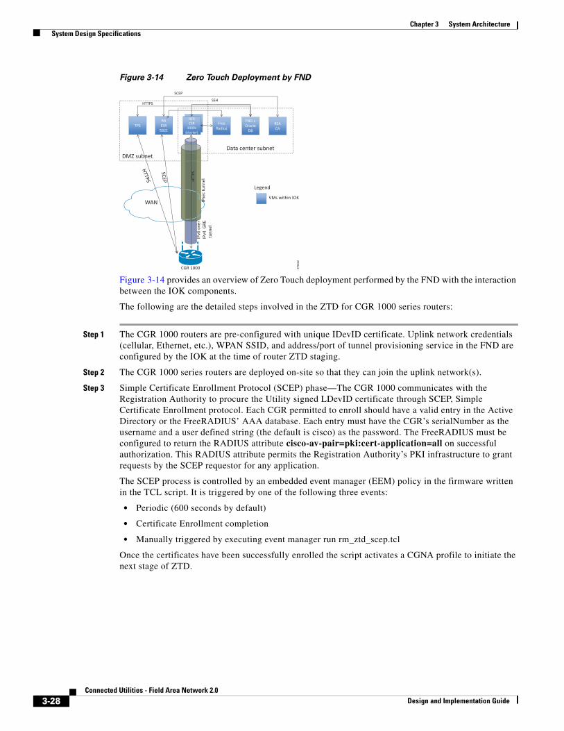
Figure 3-14 Zero Touch Deployment by FND
Figure 3-14 provides an overview of Zero Touch deployment performed by the FND with the interaction between the IOK components.
The following are the detailed steps involved in the ZTD for CGR 1000 series routers:
Step 1 The CGR 1000 routers are pre-configured with unique IDevID certificate. Uplink network credentials (cellular, Ethernet, etc.), WPAN SSID, and address/port of tunnel provisioning service in the FND are configured by the IOK at the time of router ZTD staging.
Step 2 The CGR 1000 series routers are deployed on-site so that they can join the uplink network(s).
Step 3 Simple Certificate Enrollment Protocol (SCEP) phase—The CGR 1000 communicates with the Registration Authority to procure the Utility signed LDevID certificate through SCEP, Simple Certificate Enrollment protocol. Each CGR permitted to enroll should have a valid entry in the Active Directory or the FreeRADIUS’ AAA database. Each entry must have the CGR’s serialNumber as the username and a user defined string (the default is cisco) as the password. The FreeRADIUS must be configured to return the RADIUS attribute cisco-av-pair=pki:cert-application=all on successful authorization. This RADIUS attribute permits the Registration Authority’s PKI infrastructure to grant requests by the SCEP requestor for any application.
The SCEP process is controlled by an embedded event manager (EEM) policy in the firmware written in the TCL script. It is triggered by one of the following three events:
• Periodic (600 seconds by default)
• Certificate Enrollment completion
• Manually triggered by executing event manager run rm_ztd_scep.tcl
Once the certificates have been successfully enrolled the script activates a CGNA profile to initiate the next stage of ZTD.
3756
22
TPS RA ESR
5921
HER CSR
1000v (cluster)
Free Radius
FND + Oracle
DB
DMZ subnet Data center subnet
IPse
c tu
nnel
IP
v6 o
ver
IPv4
GRE
tu
nnel
WAN
CGR 1000
SCEP
SSH HTTPS
Legend
VMs within IOK HT
TPS
RSA CA
3-28Connected Utilities - Field Area Network 2.0
Design and Implementation Guide
Chapter 3 System Architecture System Design Specifications
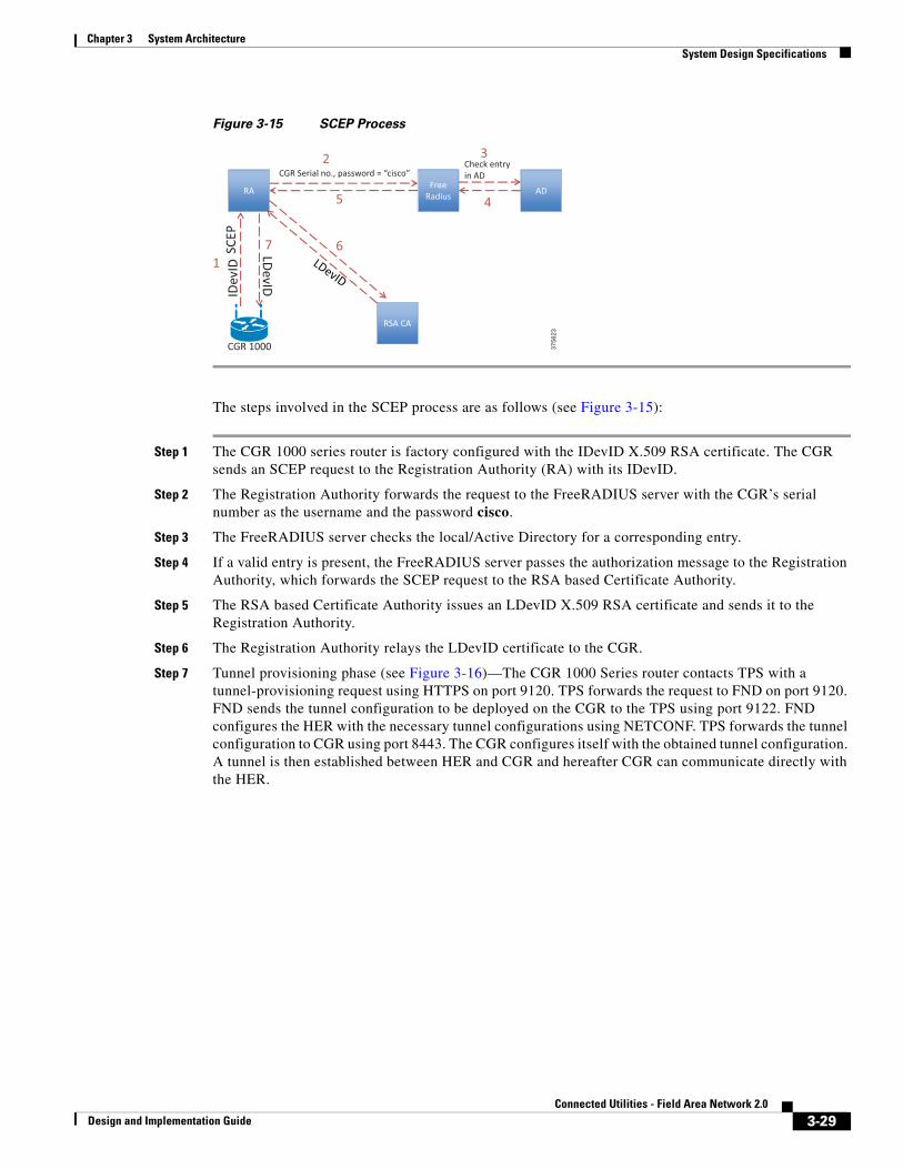
Figure 3-15 SCEP Process
The steps involved in the SCEP process are as follows (see Figure 3-15):
Step 1 The CGR 1000 series router is factory configured with the IDevID X.509 RSA certificate. The CGR sends an SCEP request to the Registration Authority (RA) with its IDevID.
Step 2 The Registration Authority forwards the request to the FreeRADIUS server with the CGR’s serial number as the username and the password cisco.
Step 3 The FreeRADIUS server checks the local/Active Directory for a corresponding entry.
Step 4 If a valid entry is present, the FreeRADIUS server passes the authorization message to the Registration Authority, which forwards the SCEP request to the RSA based Certificate Authority.
Step 5 The RSA based Certificate Authority issues an LDevID X.509 RSA certificate and sends it to the Registration Authority.
Step 6 The Registration Authority relays the LDevID certificate to the CGR.
Step 7 Tunnel provisioning phase (see Figure 3-16)—The CGR 1000 Series router contacts TPS with a tunnel-provisioning request using HTTPS on port 9120. TPS forwards the request to FND on port 9120. FND sends the tunnel configuration to be deployed on the CGR to the TPS using port 9122. FND configures the HER with the necessary tunnel configurations using NETCONF. TPS forwards the tunnel configuration to CGR using port 8443. The CGR configures itself with the obtained tunnel configuration. A tunnel is then established between HER and CGR and hereafter CGR can communicate directly with the HER.
3756
23
RA Free Radius
SCE
P ID
evID
CGR Serial no., password = “cisco”
RSA CA
AD
Check entry in AD
CGR 1000
1
2 3
4 5
6 7 LDevID
3-29Connected Utilities - Field Area Network 2.0
Design and Implementation Guide
Chapter 3 System Architecture System Design Specifications
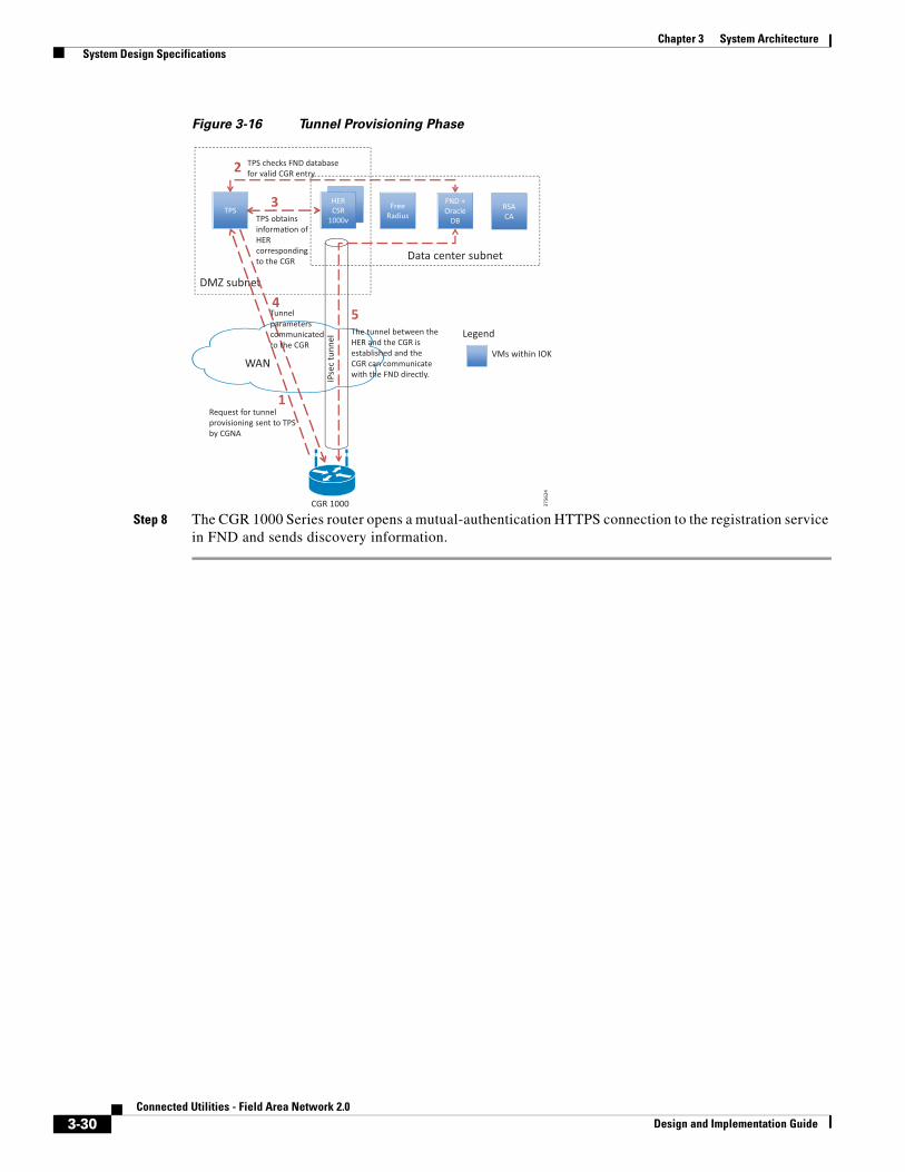
Figure 3-16 Tunnel Provisioning Phase
Step 8 The CGR 1000 Series router opens a mutual-authentication HTTPS connection to the registration service in FND and sends discovery information.
3756
24
HER CSR
1000v TPS HER CSR
1000v
Free Radius
FND + Oracle
DB
DMZ subnet
Data center subnet
IPse
c tu
nnel
WAN
CGR 1000
Legend
VMs within IOK
RSA CA
1 Request for tunnel provisioning sent to TPS by CGNA
TPS checks FND database for valid CGR entry 2
3 TPS obtains informa�on of HER corresponding to the CGR
4 5 The tunnel between the HER and the CGR is established and the CGR can communicate with the FND directly.
Tunnel parameters communicated to the CGR
3-30Connected Utilities - Field Area Network 2.0
Design and Implementation Guide
Chapter 3 System Architecture System Design Specifications
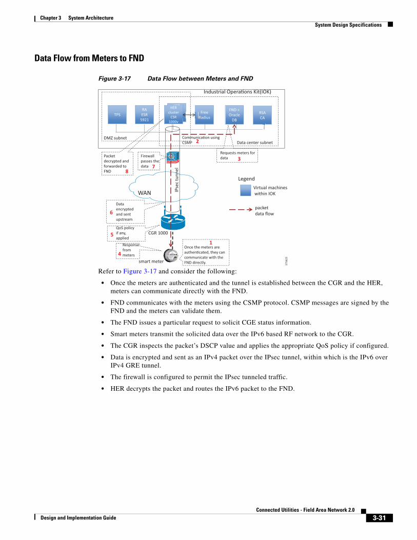
Data Flow from Meters to FND
Figure 3-17 Data Flow between Meters and FND
Refer to Figure 3-17 and consider the following:
• Once the meters are authenticated and the tunnel is established between the CGR and the HER, meters can communicate directly with the FND.
• FND communicates with the meters using the CSMP protocol. CSMP messages are signed by the FND and the meters can validate them.
• The FND issues a particular request to solicit CGE status information.
• Smart meters transmit the solicited data over the IPv6 based RF network to the CGR.
• The CGR inspects the packet’s DSCP value and applies the appropriate QoS policy if configured.
• Data is encrypted and sent as an IPv4 packet over the IPsec tunnel, within which is the IPv6 over IPv4 GRE tunnel.
• The firewall is configured to permit the IPsec tunneled traffic.
• HER decrypts the packet and routes the IPv6 packet to the FND.
3756
25
HER cluster
CSR 1000v
TPS RA ESR
5921
HER cluster
CSR 1000v
Free Radius
FND + Oracle
DB
DMZ subnet Data center subnet
IPse
c tu
nnel
WAN
CGR 1000
Legend Virtual machines within IOK
RSA CA
smart meter
packet data flow
Industrial Opera�ons Kit(IOK)
Once the meters are authen�cated, they can communicate with the FND directly.
Communica�on using CSMP
Requests meters for data
Response from meters
QoS policy if any, applied
Data encrypted and sent upstream
Firewall passes the data
Packet decrypted and forwarded to FND
1
3
4
2
6
5
7 8
3-31Connected Utilities - Field Area Network 2.0
Design and Implementation Guide
Chapter 3 System Architecture System Design Specifications
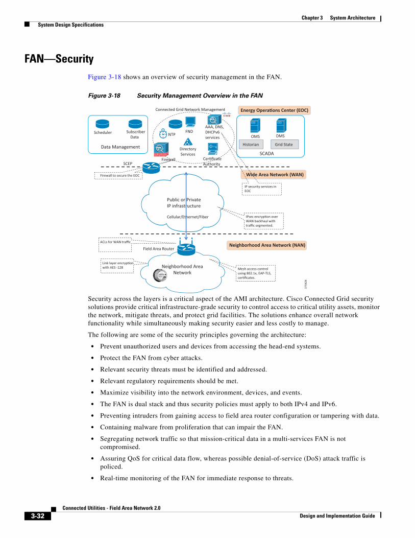
FAN—SecurityFigure 3-18 shows an overview of security management in the FAN.
Figure 3-18 Security Management Overview in the FAN
Security across the layers is a critical aspect of the AMI architecture. Cisco Connected Grid security solutions provide critical infrastructure-grade security to control access to critical utility assets, monitor the network, mitigate threats, and protect grid facilities. The solutions enhance overall network functionality while simultaneously making security easier and less costly to manage.
The following are some of the security principles governing the architecture:
• Prevent unauthorized users and devices from accessing the head-end systems.
• Protect the FAN from cyber attacks.
• Relevant security threats must be identified and addressed.
• Relevant regulatory requirements should be met.
• Maximize visibility into the network environment, devices, and events.
• The FAN is dual stack and thus security policies must apply to both IPv4 and IPv6.
• Preventing intruders from gaining access to field area router configuration or tampering with data.
• Containing malware from proliferation that can impair the FAN.
• Segregating network traffic so that mission-critical data in a multi-services FAN is not compromised.
• Assuring QoS for critical data flow, whereas possible denial-of-service (DoS) attack traffic is policed.
• Real-time monitoring of the FAN for immediate response to threats.
3756
26
Public or Private IP infrastructure Cellular/Ethernet/Fiber
Energy Opera�ons Center (EOC)
Neighborhood Area Network (NAN)
Wide Area Network (WAN)
Firewall
FND AAA, DNS, DHCPv6 services
Cer�ficate Authority
Directory Services
NTP
Neighborhood Area Network
Field Area Router
IP security services in EOC
Firewall to secure the EOC
SCEP
Link layer encryp�on with AES -128
Connected Grid Network Management
Mesh access control using 802.1x, EAP-TLS, cer�ficates.
IPsec encryp�on over WAN backhaul with traffic segmented.
ACLs for WAN traffic
Data Management
Scheduler Subscriber Data OMS DMS
SCADA
Grid State Historian
3-32Connected Utilities - Field Area Network 2.0
Design and Implementation Guide
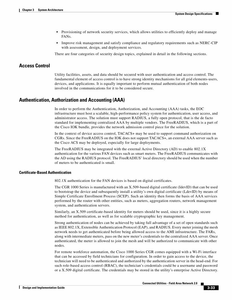
Chapter 3 System Architecture System Design Specifications
• Provisioning of network security services, which allows utilities to efficiently deploy and manage FANs.
• Improve risk management and satisfy compliance and regulatory requirements such as NERC-CIP with assessment, design, and deployment services.
There are four categories of security design topics, explained in detail in the following sections.
Access Control
Utility facilities, assets, and data should be secured with user authentication and access control. The fundamental element of access control is to have strong identity mechanisms for all grid elements-users, devices, and applications. It is equally important to perform mutual authentication of both nodes involved in the communications for it to be considered secure.
Authentication, Authorization and Accounting (AAA)
In order to perform the Authentication, Authorization, and Accounting (AAA) tasks, the EOC infrastructure must host a scalable, high-performance policy system for authentication, user access, and administrator access. The solution must support RADIUS, a fully open protocol, that is the de facto standard for implementing centralized AAA by multiple vendors. The FreeRADIUS, which is a part of the Cisco IOK bundle, provides the network admission control piece for the solution.
In the context of device access control, TACACS+ may be used to support command authorization on CGRs. Since the FreeRADIUS on the IOK does not support TACACS+, an external AAA server such as the Cisco ACS may be deployed, especially for large deployments.
The FreeRADIUS may be integrated with the external Active Directory (AD) to enable 802.1X authentication for the various FAN devices such as smart meters. The FreeRADIUS communicates with the AD using the RADIUS protocol. The FreeRADIUS’ local directory should be used when the number of meters to be authenticated is small.
Certificate-Based Authentication
802.1X authentication for the FAN devices is based on digital certificates.
The CGR 1000 Series is manufactured with an X.509-based digital certificate (IdevID) that can be used to bootstrap the device and subsequently install a utility’s own digital certificate (LdevID) by means of Simple Certificate Enrollment Process (SCEP). Such an identity then forms the basis of AAA services performed by the router with other entities, such as meters, aggregation routers, network management system, and authentication servers.
Similarly, an X.509 certificate-based identity for meters should be used, since it is a highly secure method for authentication, as well as for scalable cryptographic key management.
Strong authentication of nodes can be achieved by taking full advantage of a set of open standards such as IEEE 802.1X, Extensible Authentication Protocol (EAP), and RADIUS. Every meter joining the mesh network needs to get authenticated before being allowed access to the AMI infrastructure. The FARs, along with intermediate meters, pass on the new meter’s credentials to the centralized AAA server. Once authenticated, the meter is allowed to join the mesh and will be authorized to communicate with other nodes.
For remote workforce automation, the Cisco 1000 Series CGR comes equipped with a Wi-Fi interface that can be accessed by field technicians for configuration. In order to gain access to the device, the technician will need to be authenticated and authorized by the authentication server in the head-end. For such role-based access control (RBAC), the technician’s credentials could be a username and password or a X.509 digital certificate. The credentials may be stored in the utility’s enterprise Active Directory.
3-33Connected Utilities - Field Area Network 2.0
Design and Implementation Guide
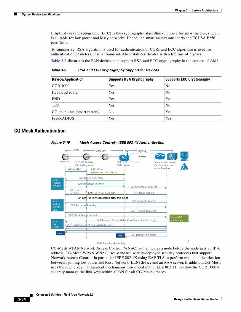
Chapter 3 System Architecture System Design Specifications
Elliptical curve cryptography (ECC) is the cryptography algorithm of choice for smart meters, since it is suitable for low power and lossy networks. Hence, the smart meters must carry the ECDSA P256 certificate.
To summarize, RSA algorithm is used for authentication of CGRs and ECC algorithm is used for authentication of meters. It is recommended to install certificates with a lifetime of 5 years.
Table 3-5 illustrates the FAN devices that support RSA and ECC cryptography in the context of AMI.
CG Mesh Authentication
Figure 3-19 Mesh Access Control—IEEE 802.1X Authentication
CG-Mesh WPAN Network Access Control (WNAC) authenticates a node before the node gets an IPv6 address. CG-Mesh WPAN WNAC uses standard, widely-deployed security protocols that support Network Access Control, in particular IEEE 802.1X using EAP-TLS to perform mutual authentication between a joining low power and lossy Network (LLN) device and an AAA server. In addition, CG-Mesh uses the secure key management mechanisms introduced in the IEEE 802.11i to allow the CGR 1000 to securely manage the link keys within a PAN for all CG-Mesh devices.
Table 3-5 RSA and ECC Cryptography Support for Devices
Device/Application Supports RSA Cryptography Supports ECC Cryptography
CGR 1000 Yes No
Head-end router Yes No
FND Yes Yes
TPS Yes No
CG endpoints (smart meters) No Yes
FreeRADIUS Yes Yes
3756
27
IP WAN
Authen�ca�on Server Cer�ficate Authority Ac�ve Directory
CGR - Split Authen�cator
EAPoL-Start EAPoL-Start relayed over UDP (EAPoU)
RADIUS Access-Request
Send AAA X.509 Cert
EAP-TLS in Radius EAP-TLS in EAPoL in UDP EAP-TLS in EAPoL
Send Subject of X.509
Supplicant “IEEE 802.1x Relay Split Authen�cator”
EAP-Request Iden�ty
EAP-Response Iden�ty
All EAP-TLS is encapsulated a�er this point EAP Request Iden�ty
EAP Response Iden�ty Send Subject of X.509 Cert EAP Request TLS Start
EAP Client Response Hello
EAP-Request Server Hello, Cer�ficate, Key Exchange
EAP-Response Client Key Exchange, Cert Send Own X.509
EAP-Request Finished PMK
PMK: Pairwise Master Key
PMK
RADIUS EAPoL EAPoUDP
n
3-34Connected Utilities - Field Area Network 2.0
Design and Implementation Guide
Chapter 3 System Architecture System Design Specifications
LLNs are typically composed of multiple hops and CG-Mesh is used to support EAPOL over multi-hop networks. In particular, the Supplicant (LLN device) might not be within direct link connectivity of the Authenticator (CGR 1000). CG-Mesh uses the Split Authenticator as a communication relay for the Authenticator. All devices that have successfully joined the network also serve as a Split Authenticator, accepting EAPOL frames from those devices that are attempting to join the network. Because CG-Mesh performs IP-layer routing, the Split Authenticator relays EAPOL frames between a joining device and an Authenticator using UDP. By introducing a Split Authenticator, the authentication and key management protocol is identical to an LLN device regardless of whether it is a single hop from the CGR 1000 or multiple hops away.
The CGR 1000 and CG-Mesh devices use the IEEE 802.11 key hierarchy in persistent state to minimize the overhead of maintaining and distributing group keys. In particular, an LLN device first checks if it has a valid Group Temporal Key (GTK) by verifying the key with one of its neighbors. If the GTK is valid, the node can begin communicating in the network immediately. Otherwise, the device then checks if it has a valid Pairwise Temporal Key (PTK) with the CGR 1000. The PTK is used to securely distribute the GTK. The same handshake messages might be used to refresh the GTK. If the PTK is valid, the CGR 1000 initiates a two-way handshake to communicate the current GTK. Otherwise, the device checks if it has a valid Pairwise Master Key (PMK) with the CGR 1000. If the PMK is valid, the CGR 1000 initiates a two-way handshake to establish a new PTK and communicate the current GTK. Otherwise, the device will request a full EAP-TLS authentication exchange. This hierarchical decision process minimizes the security overhead in the normal case, where devices might migrate from network-to-network due to environmental changes or network formation after a power outage.
The CG-Mesh meter must go through the following five stages of authentication before it connects with the CGR 1000:
• Stage 1: Key information exchange.
• Stage 2: 8021X/EAP-TLS authentication (ECC cipher suite certificate).
• Stage 3: 802.11i four-way handshake to establish a Pairwise Temporal Key (PTK) between a device and a CGR -Pairwise Master Key (PMK) confirmation, Pairwise Transient Key (PTK) derivation, and Group Temporal Key (GTK) distribution.
• Stage 4: Group key handshake.
• Stage 5: Secure data communication.
A compromised node is one where the device can no longer be trusted by the network. To evict compromised nodes from a network, the CGR must communicate a new Group Temporal Key (GTK) to all nodes in the PAN except those being evicted. The new GTK has a valid lifetime that begins immediately. After the new GTK is distributed to all allowed nodes, the CGR invalidates the old GTK. After the old GTK is invalidated, those nodes that did not receive the new GTK can no longer participate in the network and are considered evicted.
Data Integrity, Confidentiality, and Privacy
Encryption across the Network Layers
One of the critical security requirements in the FAN is to ensure data integrity and confidentiality for data from smart meters and distribution automation devices when it traverses any public or private network. Data confidentiality uses encryption mechanisms available at various layers of the communication stack. For example, an IPv6 node in the last mile, namely, a smart meter, can encrypt data using Advanced Encryption Standard (AES) at the following layers:
• Layer 2 (IEEE 802.15.4g or IEEE P1901.2)
• Layer 3 (IP Security [IPsec])
3-35Connected Utilities - Field Area Network 2.0
Design and Implementation Guide
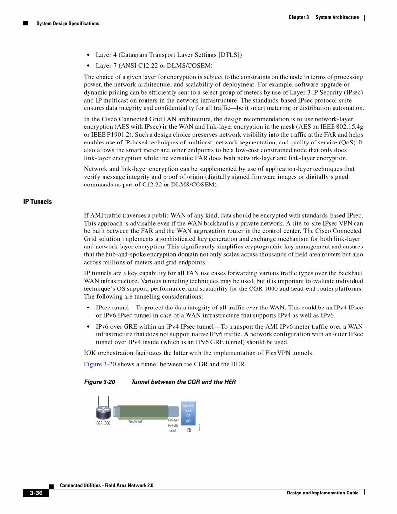
Chapter 3 System Architecture System Design Specifications
• Layer 4 (Datagram Transport Layer Settings [DTLS])
• Layer 7 (ANSI C12.22 or DLMS/COSEM)
The choice of a given layer for encryption is subject to the constraints on the node in terms of processing power, the network architecture, and scalability of deployment. For example, software upgrade or dynamic pricing can be efficiently sent to a select group of meters by use of Layer 3 IP Security (IPsec) and IP multicast on routers in the network infrastructure. The standards-based IPsec protocol suite ensures data integrity and confidentiality for all traffic—be it smart metering or distribution automation.
In the Cisco Connected Grid FAN architecture, the design recommendation is to use network-layer encryption (AES with IPsec) in the WAN and link-layer encryption in the mesh (AES on IEEE 802.15.4g or IEEE P1901.2). Such a design choice preserves network visibility into the traffic at the FAR and helps enables use of IP-based techniques of multicast, network segmentation, and quality of service (QoS). It also allows the smart meter and other endpoints to be a low-cost constrained node that only does link-layer encryption while the versatile FAR does both network-layer and link-layer encryption.
Network and link-layer encryption can be supplemented by use of application-layer techniques that verify message integrity and proof of origin (digitally signed firmware images or digitally signed commands as part of C12.22 or DLMS/COSEM).
IP Tunnels
If AMI traffic traverses a public WAN of any kind, data should be encrypted with standards-based IPsec. This approach is advisable even if the WAN backhaul is a private network. A site-to-site IPsec VPN can be built between the FAR and the WAN aggregation router in the control center. The Cisco Connected Grid solution implements a sophisticated key generation and exchange mechanism for both link-layer and network-layer encryption. This significantly simplifies cryptographic key management and ensures that the hub-and-spoke encryption domain not only scales across thousands of field area routers but also across millions of meters and grid endpoints.
IP tunnels are a key capability for all FAN use cases forwarding various traffic types over the backhaul WAN infrastructure. Various tunneling techniques may be used, but it is important to evaluate individual technique’s OS support, performance, and scalability for the CGR 1000 and head-end router platforms. The following are tunneling considerations:
• IPsec tunnel—To protect the data integrity of all traffic over the WAN. This could be an IPv4 IPsec or IPv6 IPsec tunnel in case of a WAN infrastructure that supports IPv4 as well as IPv6.
• IPv6 over GRE within an IPv4 IPsec tunnel—To transport the AMI IPv6 meter traffic over a WAN infrastructure that does not support native IPv6 traffic. A network configuration with an outer IPsec tunnel over IPv4 inside (which is an IPv6 GRE tunnel) should be used.
IOK orchestration facilitates the latter with the implementation of FlexVPN tunnels.
Figure 3-20 shows a tunnel between the CGR and the HER.
Figure 3-20 Tunnel between the CGR and the HER
IPSec tunnel IPv6 over IPv4 GRE tunnel
Head-end Router
CSR 1000v CGR 1000 HER 3
75
62
8
3-36Connected Utilities - Field Area Network 2.0
Design and Implementation Guide
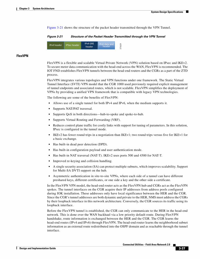
Chapter 3 System Architecture System Design Specifications
Figure 3-21 shows the structure of the packet header transmitted through the VPN Tunnel.
Figure 3-21 Structure of the Packet Header Transmitted through the VPN Tunnel
FlexVPN
FlexVPN is a flexible and scalable Virtual Private Network (VPN) solution based on IPsec and IKEv2. To secure meter data communication with the head-end across the WAN, FlexVPN is recommended. The IOT FND establishes FlexVPN tunnels between the head-end routers and the CGRs as a part of the ZTD process.
FlexVPN integrates various topologies and VPN functions under one framework. The Static Virtual Tunnel Interface (SVTI) VPN model that the CGR 1000 used previously required explicit management of tunnel endpoints and associated routes, which is not scalable. FlexVPN simplifies the deployment of VPNs by providing a unified VPN framework that is compatible with legacy VPN technologies.
The following are some of the benefits of FlexVPN:
• Allows use of a single tunnel for both IPv4 and IPv6, when the medium supports it.
• Supports NAT/PAT traversal.
• Supports QoS in both directions—hub-to-spoke and spoke-to-hub.
• Supports Virtual Routing and Forwarding (VRF).
• Reduces control plane traffic for costly links with support for tuning of parameters. In this solution, IPsec is configured in the tunnel mode.
• IKEv2 has fewer round trips in a negotiation than IKEv1; two round trips versus five for IKEv1 for a basic exchange.
• Has built-in dead peer detection (DPD).
• Has built-in configuration payload and user authentication mode.
• Has built-in NAT traversal (NAT-T). IKEv2 uses ports 500 and 4500 for NAT-T.
• Improved re-keying and collision handling.
• A single security association (SA) can protect multiple subnets, which improves scalability. Support for Multi-SA DVTI support on the hub.
• Asymmetric authentication in site-to-site VPNs, where each side of a tunnel can have different preshared keys, different certificates, or one side a key and the other side a certificate.
In the FlexVPN VPN model, the head-end router acts as the FlexVPN hub and CGRs act as the FlexVPN spokes. The tunnel interfaces on the CGR acquire their IP addresses from address pools configured during IOK installation. These addresses only have local significance between the HER and the CGR. Since the CGR’s tunnel addresses are both dynamic and private to the HER, NMS must address the CGRs by their loopback interface in this network architecture. Conversely, the CGR sources its traffic using its loopback interface.
Before the FlexVPN tunnel is established, the CGR can only communicate to the HER in the head-end network. This is done over the WAN backhaul via a low priority default route. During FlexVPN handshake, route information is exchanged between the HER and the CGR. The CGR learns the head-end routes (IPv4 and IPv6) through FlexVPN. The head-end router learns the neighborhood subnet information as an external route redistributed into the OSPF domain and as reachable through the tunnel interface.
3756
29IPv6 data and header
IPv4 GRE header IPSec header IPv4 header
3-37Connected Utilities - Field Area Network 2.0
Design and Implementation Guide
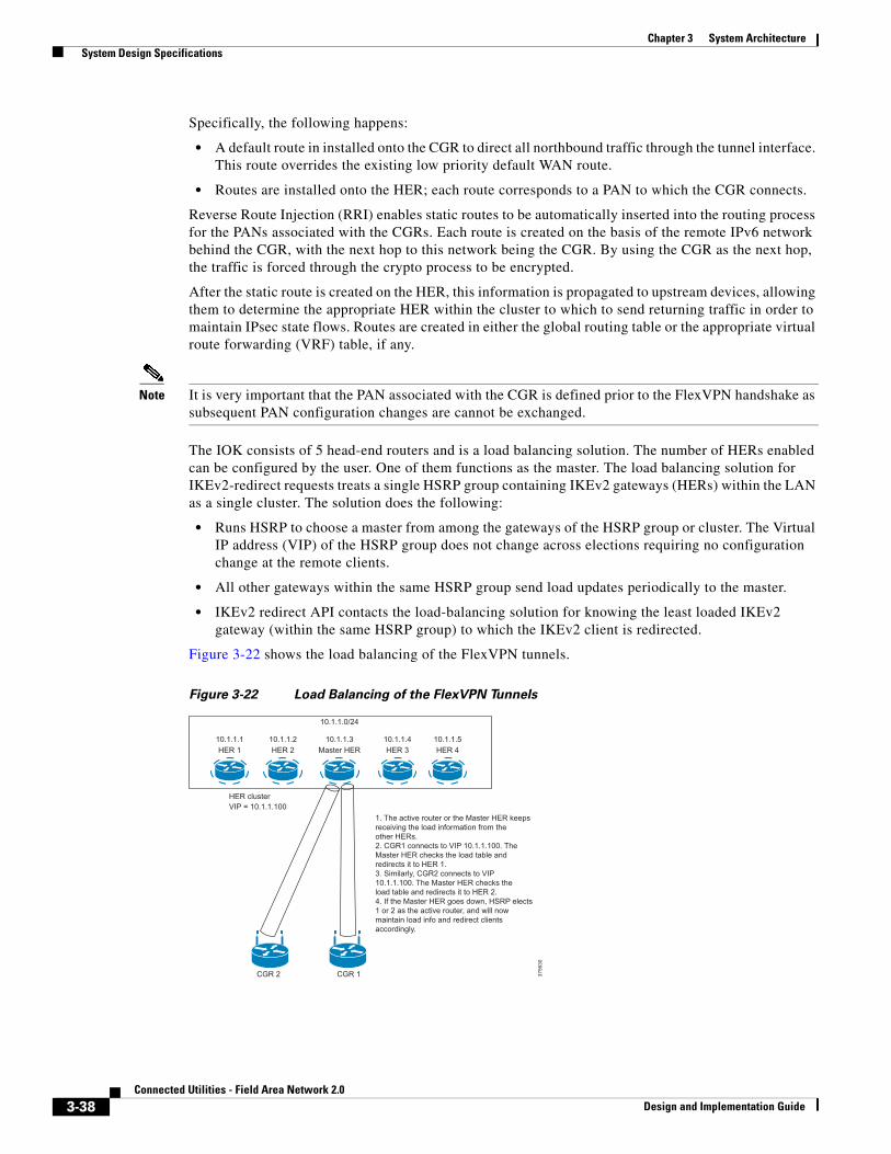
Chapter 3 System Architecture System Design Specifications
Specifically, the following happens:
• A default route in installed onto the CGR to direct all northbound traffic through the tunnel interface. This route overrides the existing low priority default WAN route.
• Routes are installed onto the HER; each route corresponds to a PAN to which the CGR connects.
Reverse Route Injection (RRI) enables static routes to be automatically inserted into the routing process for the PANs associated with the CGRs. Each route is created on the basis of the remote IPv6 network behind the CGR, with the next hop to this network being the CGR. By using the CGR as the next hop, the traffic is forced through the crypto process to be encrypted.
After the static route is created on the HER, this information is propagated to upstream devices, allowing them to determine the appropriate HER within the cluster to which to send returning traffic in order to maintain IPsec state flows. Routes are created in either the global routing table or the appropriate virtual route forwarding (VRF) table, if any.
Note It is very important that the PAN associated with the CGR is defined prior to the FlexVPN handshake as subsequent PAN configuration changes are cannot be exchanged.
The IOK consists of 5 head-end routers and is a load balancing solution. The number of HERs enabled can be configured by the user. One of them functions as the master. The load balancing solution for IKEv2-redirect requests treats a single HSRP group containing IKEv2 gateways (HERs) within the LAN as a single cluster. The solution does the following:
• Runs HSRP to choose a master from among the gateways of the HSRP group or cluster. The Virtual IP address (VIP) of the HSRP group does not change across elections requiring no configuration change at the remote clients.
• All other gateways within the same HSRP group send load updates periodically to the master.
• IKEv2 redirect API contacts the load-balancing solution for knowing the least loaded IKEv2 gateway (within the same HSRP group) to which the IKEv2 client is redirected.
Figure 3-22 shows the load balancing of the FlexVPN tunnels.
Figure 3-22 Load Balancing of the FlexVPN Tunnels
3756
30
1. The active router or the Master HER keepsreceiving the load information from the other HERs.2. CGR1 connects to VIP 10.1.1.100. TheMaster HER checks the load table andredirects it to HER 1.3. Similarly, CGR2 connects to VIP10.1.1.100. The Master HER checks theload table and redirects it to HER 2.4. If the Master HER goes down, HSRP elects1 or 2 as the active router, and will nowmaintain load info and redirect clientsaccordingly.
CGR 2 CGR 1
10.1.1.0/24
10.1.1.1 10.1.1.2 10.1.1.3 10.1.1.4 10.1.1.5HER 1 HER 2 HER 3 HER 4Master HER
HER clusterVIP = 10.1.1.100
3-38Connected Utilities - Field Area Network 2.0
Design and Implementation Guide
Chapter 3 System Architecture System Design Specifications
The head-end routers are pre-configured to support FlexVPN, hence no additional configuration on the HER is required to create the tunnel. Configurations only need to be made on the CGR and this is done as a part of the ZTD process. Registration of the CGR does not occur until the IPsec tunnel is successfully brought up.
Threat Detection and Mitigation
Data Segmentation
A simple but powerful network security technique is to logically separate different functional elements that should never be communicating with each other. For example, in the distribution grid, smart meters should not be communicating to Distribution Automation devices and vice versa. Similarly, traffic originating from field technicians should be logically separated from AMI and DA traffic. The Cisco Connected Grid security architecture supports tools such as VLANs and Generic Routing Encapsulation (GRE) to achieve network segmentation. To build on top of that, access lists and firewall features can be configured on field area routers to filter and control access in the distribution and substation part of the grid.
VLAN Segmentation
In order to segregate traffic, the VLAN design shown in Table 3-6 should be used.
Figure 3-1 on page 3-2, which illustrates the FAN system topology, shows VLAN segmentation.
Firewall
All traffic originating from the FAN is aggregated at the control-center tier and needs to be passed through a high performance firewall, especially if it has traversed through a public network. This firewall should implement zone-based policies to detect and mitigate threats. The Cisco ASA with FirePOWER Services, which brings distinctive, threat-focused, next-generation security services to the ASA 5585-X firewall products, is recommended for the solution. It provides comprehensive protection from known and advanced threats, including protection against targeted and persistent malware attacks.
The firewall must be configured in transparent mode. The interface connecting to the IOK must be configured as the inside interface and the interface connecting to the WAN link must be configured as outside, as shown in Figure 3-23.
Table 3-6 VLAN Plan
VLAN ID Description
DMZ subnet VLAN (VLAN 30) For DMZ components within the IOK.
Data center subnet VLAN (VLAN 20) For data center components in the IOK.
Collection Engine/AMI operations VLAN (VLAN 40)
For application head-end components.
Utility data center VLAN (VLAN 50) For components residing in the Utility data center.
Black hole VLAN (VLAN 90) All unused ports are assigned to this VLAN as a security measure.
3-39Connected Utilities - Field Area Network 2.0
Design and Implementation Guide
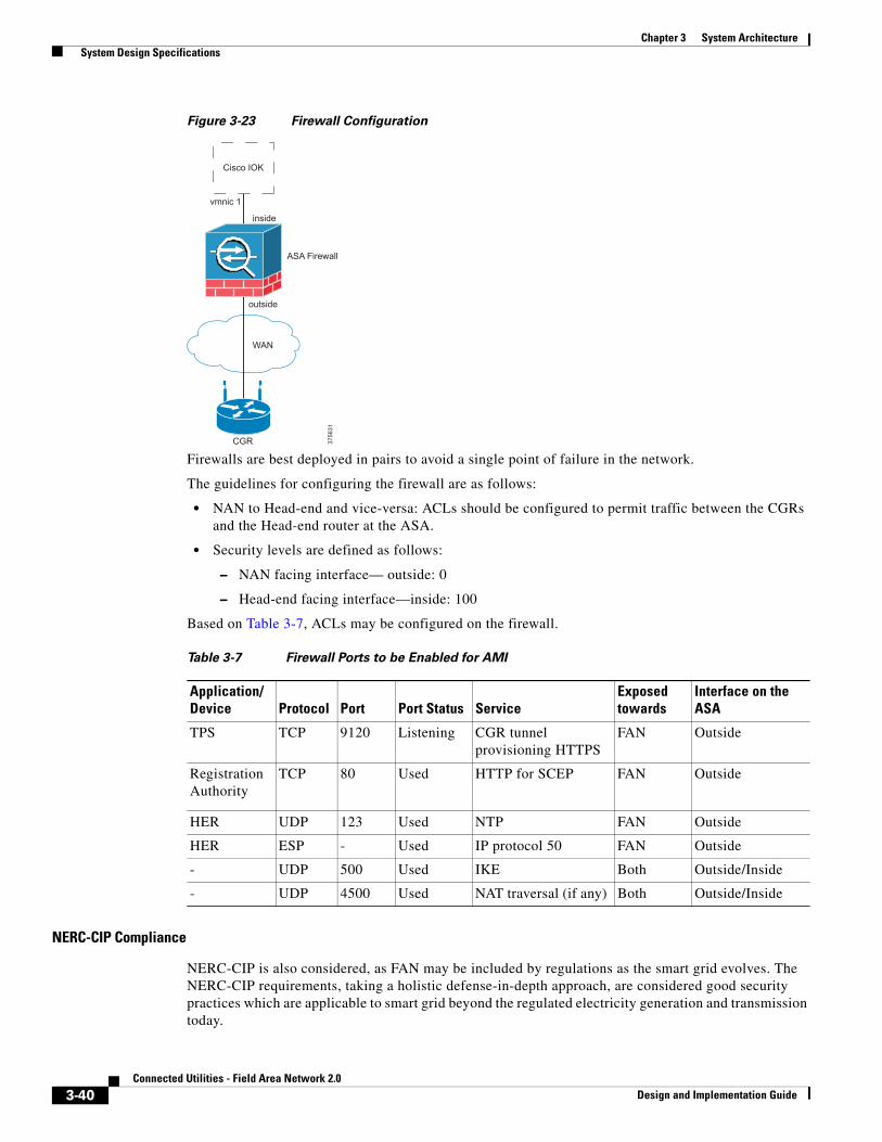
Chapter 3 System Architecture System Design Specifications
Figure 3-23 Firewall Configuration
Firewalls are best deployed in pairs to avoid a single point of failure in the network.
The guidelines for configuring the firewall are as follows:
• NAN to Head-end and vice-versa: ACLs should be configured to permit traffic between the CGRs and the Head-end router at the ASA.
• Security levels are defined as follows:
– NAN facing interface— outside: 0
– Head-end facing interface—inside: 100
Based on Table 3-7, ACLs may be configured on the firewall.
NERC-CIP Compliance
NERC-CIP is also considered, as FAN may be included by regulations as the smart grid evolves. The NERC-CIP requirements, taking a holistic defense-in-depth approach, are considered good security practices which are applicable to smart grid beyond the regulated electricity generation and transmission today.
WAN
3756
31
Cisco IOK
vmnic 1
inside
ASA Firewall
outside
CGR
Table 3-7 Firewall Ports to be Enabled for AMI
Application/Device Protocol Port Port Status Service
Exposed towards
Interface on the ASA
TPS TCP 9120 Listening CGR tunnel provisioning HTTPS
FAN Outside
Registration Authority
TCP 80 Used HTTP for SCEP FAN Outside
HER UDP 123 Used NTP FAN Outside
HER ESP - Used IP protocol 50 FAN Outside
- UDP 500 Used IKE Both Outside/Inside
- UDP 4500 Used NAT traversal (if any) Both Outside/Inside
3-40Connected Utilities - Field Area Network 2.0
Design and Implementation Guide
Chapter 3 System Architecture System Design Specifications
The AMI endpoints, namely the smart meters, do not fall within the classification of High or Medium impact assets. However, physical security of the endpoints remains a concern. Physical compromise may lead to tampering of meters and the cryptographic key may be retrieved from the microprocessor. This becomes especially dangerous if several meters share the same key. This can be mitigated by device authentication for meters, encryption of key exchange, VPN from aggregation points, etc. Cisco’s implementation of Zero Touch deployment capability and security from the meter communications to the Meter Data Management System provides an additional layer to the application layer security implemented by the meter vendor.
Device and Platform Integrity
Device Hardening and Tamper Proofing
A basic tenet of security design is to ensure that devices, endpoints, and applications cannot be compromised easily and are resistant to cyber attacks. With that goal in mind, the Cisco 1000 Series Connected Grid Routers are built with tamper-resistant mechanical designs. The Cisco 1240 Connected Grid Router (CGR 1240), which is an outdoor model, is equipped with a physical lock and key mechanism. This makes it extremely difficult for any rogue entity to open or uninstall the device from the pole-top mounting. The device generates NMS alerts if the router door or chassis is opened.
Additionally, each router motherboard is equipped with a dedicated security chip that provides the following:
• Secure unique device identifier (802.1AR)
• Immutable identity and certifiable cryptography
• Entropy source with true randomization
• Memory protection and image signing and validation
• Tamper-proof secure storage of configuration and data
CGR 1000 series router images are digitally signed to validate the authenticity and integrity of the software. For AMI deployments using the Cisco Connected Grid architecture, meters also have a tamper-resistant design, generate an alert on tampering, and maintain local audit trails for all sensitive events. Firmware images for meters are digitally signed. Similarly, to help ensure authenticity and integrity of commands delivered from the AMI head-end system (HES) to meters, the commands are digitally signed.
Further, the following is recommended:
• Unused ports on the switches are shut down.
• BPDU guard be enabled on the switches.
• First hop security (FHS) is enabled on the FAN devices.
FAN—High AvailabilityIOK does not support high availability of head-end systems, such as, the IoT FND. However, high availability is factored into the design at the network layer at key junctures and is cross-referenced below.
• PAN migration of endpoints in case of CGR failure (see NAN Network Connectivity, page 3-8)
• RPL is the choice of routing protocol, which supports low power and lossy networks (see NAN Routing, page 3-16)
• Load balancing of HERs to support FlexVPN tunnels (see IP Tunnels, page 3-36)
3-41Connected Utilities - Field Area Network 2.0
Design and Implementation Guide
Chapter 3 System Architecture Architecture Summary and Implementation Guidelines
Additionally, RAID (Redundant Array of Independent Discs) may be set up with ESXi to provide resiliency and high availability for storage. Refer to VMware’s guide for VMware storage best practices at:
• https://www.vmware.com/files/pdf/support/landing_pages/Virtual-Support-Day-Storage-Best-Practices-June-2012.pdf
FAN—Sizing and ScalingThe following are network sizing and scaling parameters that have been factored in for the Field Area Network system design and implementation:
• A Cisco Connected Grid 1000 series router can support up to 5000 connected grid endpoints or smart meters.
• The head-end routers of the Cisco Industrial Operations Kit are 5 in number. Each HER can support up to 300 Cisco Connected Grid 1000 series router.
• The Itron OpenWay smart meters’ usage data messages are in the order of kilobytes. For example, 2000 routers reporting every 15 minutes, spread over 15 minutes = 2.2 reports/sec, ~70kB/sec including FAR and HERs metrics. Worst-case spike load of all routers reporting at the same time, spread over 10secs = 200 reports/sec, ~7 MB/sec.
• RF capacity planning—The connected grid endpoints should be deployed on the field after appropriate RF site survey using a spectrum analyzer. The RF design can be carried out using tools such as the ATDI ICS designer or ASSET by TEOCO.
• The CGR 1000 series routers have a transmit power of 28dBm.
Architecture Summary and Implementation GuidelinesThis chapter described the system architecture and design specifications for FAN 2.0 to achieve the functionality required for the use case of Advanced Metering Infrastructure with the Cisco Industrial Operations Kit. The implementation is considered complete when there is successful two-way communication established between the smart meters and the head-end systems.
The data flow between the smart meters and the head-end systems, specifically the Cisco IoT FND and the Collection Engine, along with the stages of implementation are summarized in Figure 3-24.
3-42Connected Utilities - Field Area Network 2.0
Design and Implementation Guide
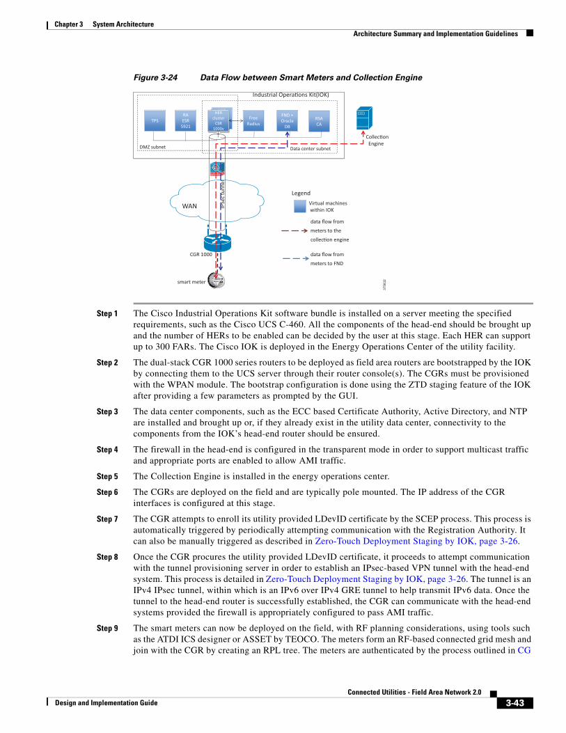
Chapter 3 System Architecture Architecture Summary and Implementation Guidelines
Figure 3-24 Data Flow between Smart Meters and Collection Engine
Step 1 The Cisco Industrial Operations Kit software bundle is installed on a server meeting the specified requirements, such as the Cisco UCS C-460. All the components of the head-end should be brought up and the number of HERs to be enabled can be decided by the user at this stage. Each HER can support up to 300 FARs. The Cisco IOK is deployed in the Energy Operations Center of the utility facility.
Step 2 The dual-stack CGR 1000 series routers to be deployed as field area routers are bootstrapped by the IOK by connecting them to the UCS server through their router console(s). The CGRs must be provisioned with the WPAN module. The bootstrap configuration is done using the ZTD staging feature of the IOK after providing a few parameters as prompted by the GUI.
Step 3 The data center components, such as the ECC based Certificate Authority, Active Directory, and NTP are installed and brought up or, if they already exist in the utility data center, connectivity to the components from the IOK’s head-end router should be ensured.
Step 4 The firewall in the head-end is configured in the transparent mode in order to support multicast traffic and appropriate ports are enabled to allow AMI traffic.
Step 5 The Collection Engine is installed in the energy operations center.
Step 6 The CGRs are deployed on the field and are typically pole mounted. The IP address of the CGR interfaces is configured at this stage.
Step 7 The CGR attempts to enroll its utility provided LDevID certificate by the SCEP process. This process is automatically triggered by periodically attempting communication with the Registration Authority. It can also be manually triggered as described in Zero-Touch Deployment Staging by IOK, page 3-26.
Step 8 Once the CGR procures the utility provided LDevID certificate, it proceeds to attempt communication with the tunnel provisioning server in order to establish an IPsec-based VPN tunnel with the head-end system. This process is detailed in Zero-Touch Deployment Staging by IOK, page 3-26. The tunnel is an IPv4 IPsec tunnel, within which is an IPv6 over IPv4 GRE tunnel to help transmit IPv6 data. Once the tunnel to the head-end router is successfully established, the CGR can communicate with the head-end systems provided the firewall is appropriately configured to pass AMI traffic.
Step 9 The smart meters can now be deployed on the field, with RF planning considerations, using tools such as the ATDI ICS designer or ASSET by TEOCO. The meters form an RF-based connected grid mesh and join with the CGR by creating an RPL tree. The meters are authenticated by the process outlined in CG
3756
32
HER cluster
CSR 1000v
TPS RA ESR
5921
HERHER cluster
CSR 1000v
Free Radius
FND + Oracle
DB
DMZ subnet Data center subnet
IPSe
c tu
nnel
WAN
CGR 1000
Legend Virtual machines within IOK
RSA CA
smart meter
Industrial Opera�ons Kit(IOK)
Collec�on Engine
data flow from
meters to the
collec�on engine
data flow from
meters to FND
3-43Connected Utilities - Field Area Network 2.0
Design and Implementation Guide
Chapter 3 System Architecture Architecture Summary and Implementation Guidelines
Mesh Authentication, page 3-34.
Step 10 The meters are provisioned with an IPv6 address by the CGR.
Step 11 The meters can now communicate with the head-end systems. The data flow from meters to the FND and collection engine is illustrated in the figure above. Data is encrypted and sent over the IPsec tunnel, within which is the IPv6 over IPv4 GRE tunnel. The firewall inspects the packet and passes it since the ports are configured to pass appropriate AMI traffic. The packet is decrypted and the HER routes the IPv6 packet to the Collection Engine or FND as appropriate.
Step 12 Management of the meters and the CGR is the primary function of the IoT FND. Communication between the FND and the CGR occurs using the CSMP protocol.
Step 13 Smart meters transmit their usage data over the IPv6 based RF network to the Collection Engine. In case of solicited meter reads, the Collection Engine sends out a meter data request.
Step 14 Multicast packets from the CGR and the Collection Engine are transmitted over the IPsec tunnel as described in IP Multicast, page 3-20.
3-44Connected Utilities - Field Area Network 2.0
Design and Implementation Guide


![Deployment Strategies for Crowdsourced Power Outage …GridWatch is a mobile-based crowdsourcing system for electricity grid outage and restoration measurement [1]. It uses sensors](https://static.fdocuments.net/doc/165x107/5f948e0f4f869b7db053e35b/deployment-strategies-for-crowdsourced-power-outage-gridwatch-is-a-mobile-based.jpg)


