
CHAPTER 3: Simple Resistive Circuits - Dr. Fehmi...
24
CHAPTER 3: Simple Resistive Circuits
Transcript of CHAPTER 3: Simple Resistive Circuits - Dr. Fehmi...
CHAPTER 3: Simple Resistive Circuits
3.1 Resistors in Series
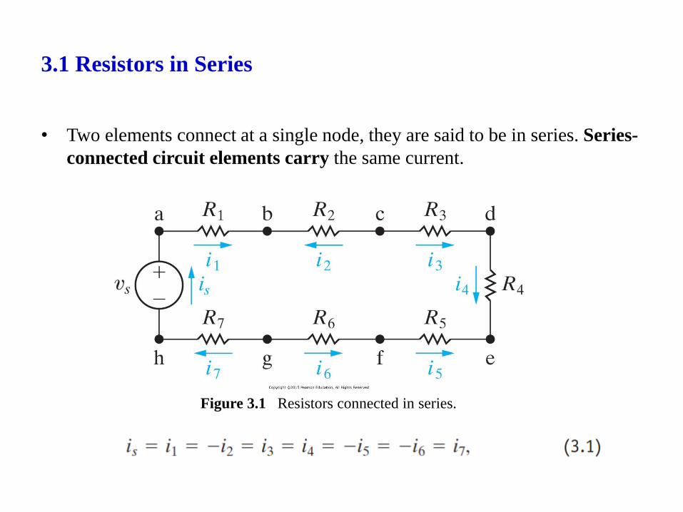
• Two elements connect at a single node, they are said to be in series. Series-
connected circuit elements carry the same current.
Figure 3.1 Resistors connected in series.
3.1 Resistors in Series
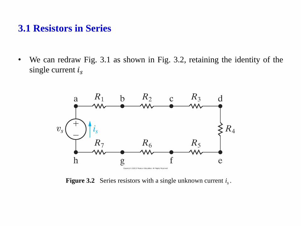
• We can redraw Fig. 3.1 as shown in Fig. 3.2, retaining the identity of the
single current 𝑖𝑠
Figure 3.2 Series resistors with a single unknown current is .
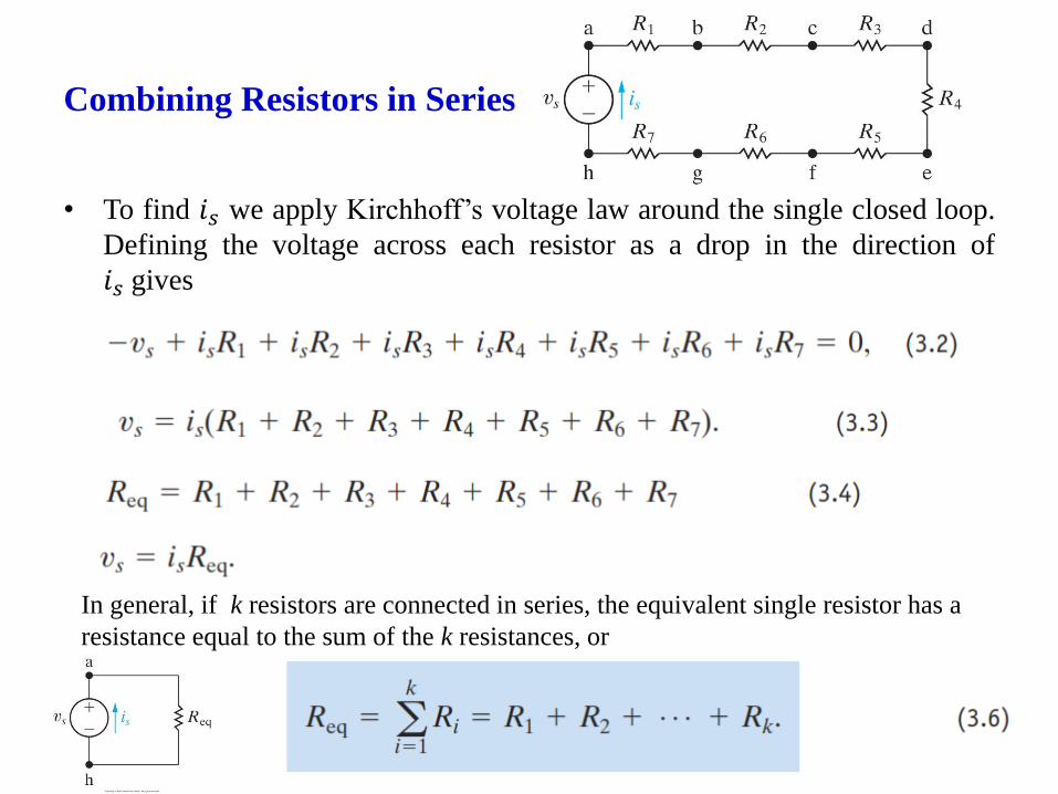
Combining Resistors in Series
• To find 𝑖𝑠 we apply Kirchhoff’s voltage law around the single closed loop.
Defining the voltage across each resistor as a drop in the direction of
𝑖𝑠 gives
In general, if k resistors are connected in series, the equivalent single resistor has a
resistance equal to the sum of the k resistances, or

Combining Resistors in Series
• An equivalent resistance is to visualize the string of resistors as being
inside a black box.
• The term black box to imply an opaque container; that is, the contents are
hidden from view. The engineer is then challenged to model the contents of
the box by studying the relationship between the voltage and current at its
terminals
• Determining whether the box contains k resistors or a single equivalent
resistor is impossible.
Figure 3.4 The black box equivalent of the circuit shown in Fig. 3.2.
The resistance of the equivalent
resistor is always larger than
that of the largest resistor in the
series connection.
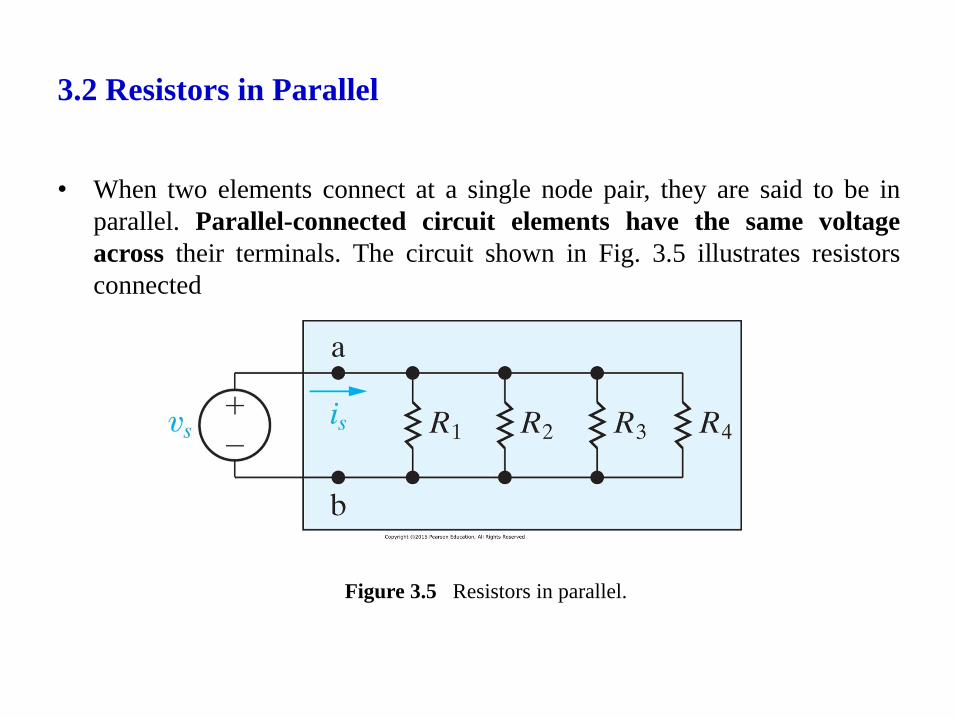
3.2 Resistors in Parallel
• When two elements connect at a single node pair, they are said to be in
parallel. Parallel-connected circuit elements have the same voltage
across their terminals. The circuit shown in Fig. 3.5 illustrates resistors
connected
Figure 3.5 Resistors in parallel.
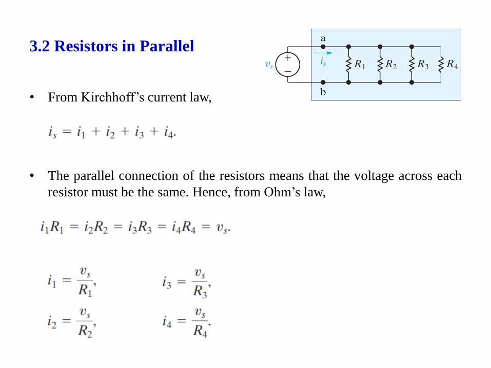
3.2 Resistors in Parallel
• From Kirchhoff’s current law,
• The parallel connection of the resistors means that the voltage across each
resistor must be the same. Hence, from Ohm’s law,

Combining Resistors in Parallel
Figure 3.7 Replacing the four
parallel resistors shown in Fig. 3.5
with a single equivalent resistor.
Figure 3.5 Resistors in parallel.
The resistance of the equivalent resistor is
always smaller than the resistance of
the smallest resistor in the parallel
connection.
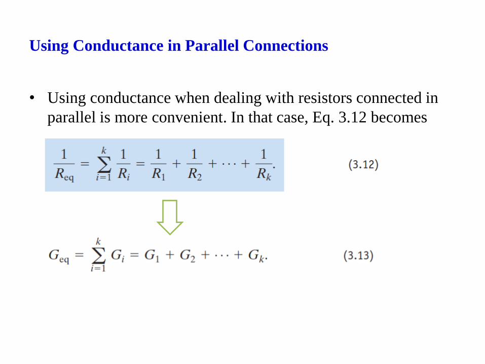
Using Conductance in Parallel Connections
• Using conductance when dealing with resistors connected in
parallel is more convenient. In that case, Eq. 3.12 becomes
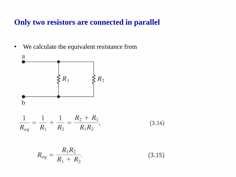
Only two resistors are connected in parallel
• We calculate the equivalent resistance from
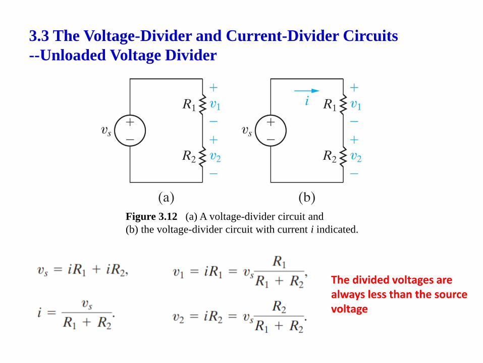
3.3 The Voltage-Divider and Current-Divider Circuits
--Unloaded Voltage Divider
Figure 3.12 (a) A voltage-divider circuit and
(b) the voltage-divider circuit with current i indicated.
The divided voltages are always less than the source voltage
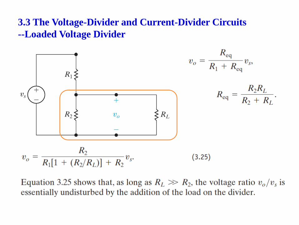
3.3 The Voltage-Divider and Current-Divider Circuits
--Loaded Voltage Divider
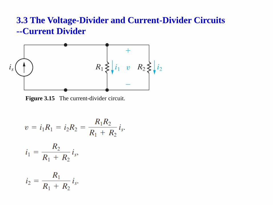
3.3 The Voltage-Divider and Current-Divider Circuits
--Current Divider
Figure 3.15 The current-divider circuit.
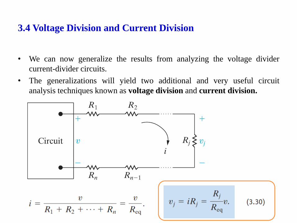
3.4 Voltage Division and Current Division
• We can now generalize the results from analyzing the voltage divider
current-divider circuits.
• The generalizations will yield two additional and very useful circuit
analysis techniques known as voltage division and current division.
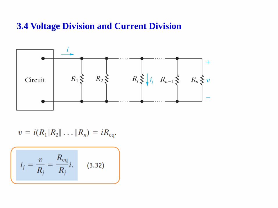
3.4 Voltage Division and Current Division
3.5 Measuring Voltage and Current
• An ammeter is an instrument designed to measure current; it is placed in
series with the circuit element whose current is being measured.
• A voltmeter is an instrument designed to measure voltage; it is placed in
parallel with the element whose voltage is being measured.
• An ideal ammeter or voltmeter has no effect on the circuit variable it is
designed to measure.
• That is, an ideal ammeter has an equivalent resistance of 𝟎𝜴 and functions
as a short circuit in series with the element whose current is being
measured.
• An ideal voltmeter has an infinite equivalent resistance and thus functions
as an open circuit in parallel with the element whose voltage is being
measured.
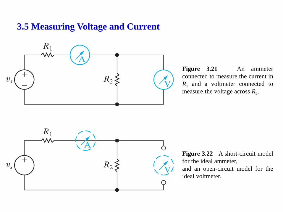
3.5 Measuring Voltage and Current
Figure 3.22 A short-circuit model
for the ideal ammeter,
and an open-circuit model for the
ideal voltmeter.
Figure 3.21 An ammeter
connected to measure the current in
R1 and a voltmeter connected to
measure the voltage across R2.
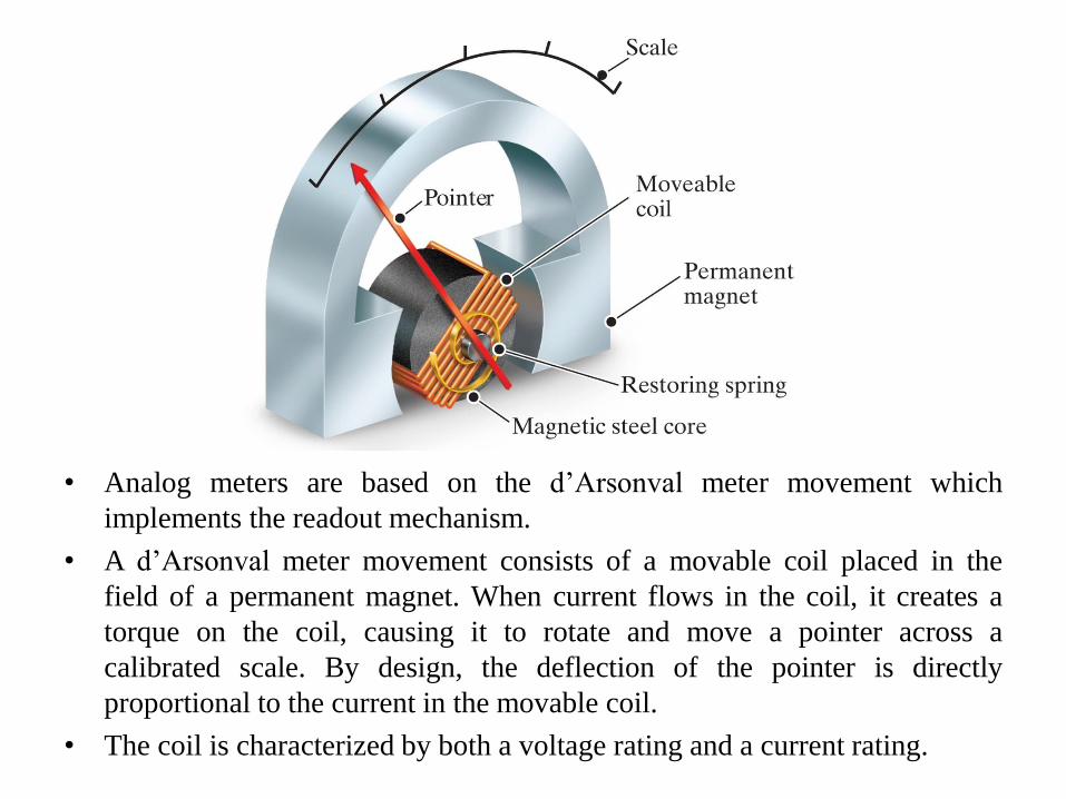
• Analog meters are based on the d’Arsonval meter movement which
implements the readout mechanism.
• A d’Arsonval meter movement consists of a movable coil placed in the
field of a permanent magnet. When current flows in the coil, it creates a
torque on the coil, causing it to rotate and move a pointer across a
calibrated scale. By design, the deflection of the pointer is directly
proportional to the current in the movable coil.
• The coil is characterized by both a voltage rating and a current rating.
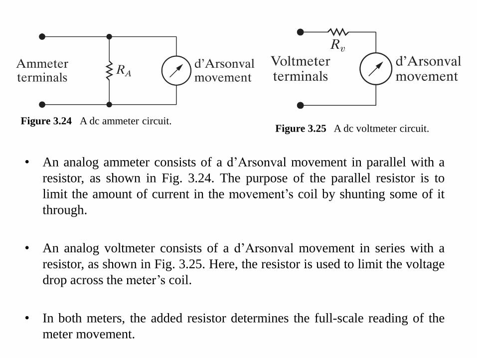
Figure 3.24 A dc ammeter circuit. Figure 3.25 A dc voltmeter circuit.
• An analog ammeter consists of a d’Arsonval movement in parallel with a
resistor, as shown in Fig. 3.24. The purpose of the parallel resistor is to
limit the amount of current in the movement’s coil by shunting some of it
through.
• An analog voltmeter consists of a d’Arsonval movement in series with a
resistor, as shown in Fig. 3.25. Here, the resistor is used to limit the voltage
drop across the meter’s coil.
• In both meters, the added resistor determines the full-scale reading of the
meter movement.
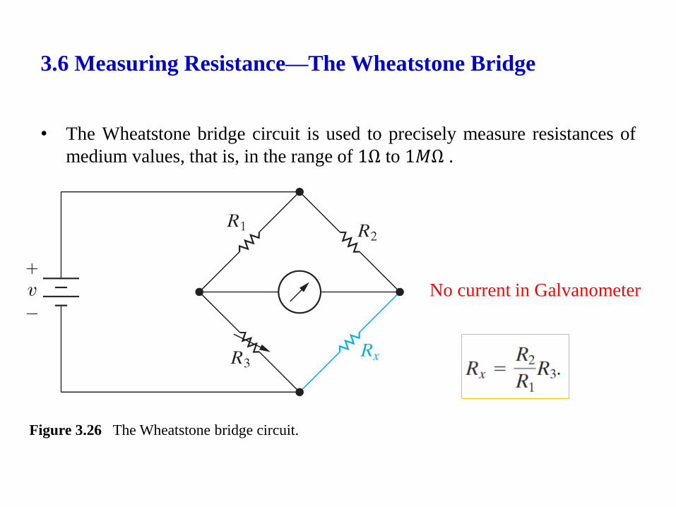
3.6 Measuring Resistance—The Wheatstone Bridge
• The Wheatstone bridge circuit is used to precisely measure resistances of
medium values, that is, in the range of 1Ω to 1𝑀Ω .
Figure 3.26 The Wheatstone bridge circuit.
No current in Galvanometer
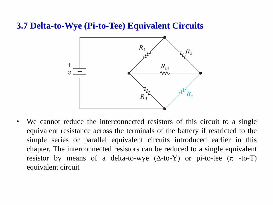
3.7 Delta-to-Wye (Pi-to-Tee) Equivalent Circuits
• We cannot reduce the interconnected resistors of this circuit to a single
equivalent resistance across the terminals of the battery if restricted to the
simple series or parallel equivalent circuits introduced earlier in this
chapter. The interconnected resistors can be reduced to a single equivalent
resistor by means of a delta-to-wye (-to-Y) or pi-to-tee ( -to-T)
equivalent circuit
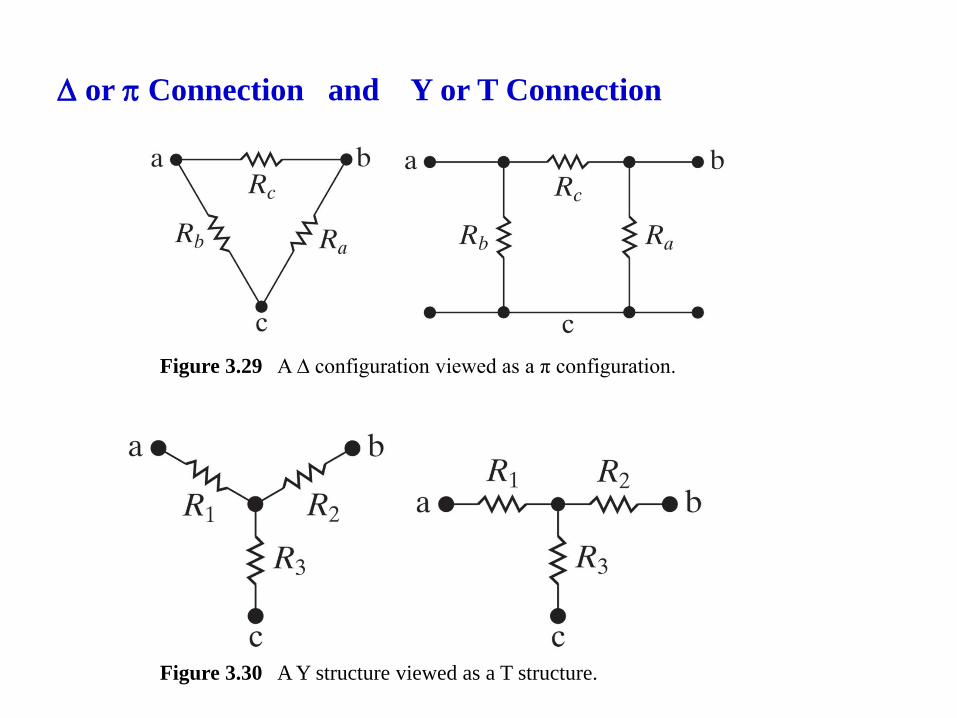
or Connection and Y or T Connection
Figure 3.29 A ∆ configuration viewed as a π configuration.
Figure 3.30 A Y structure viewed as a T structure.
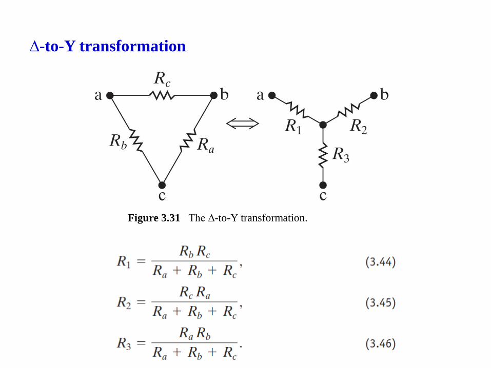
∆-to-Y transformation
Figure 3.31 The ∆-to-Y transformation.
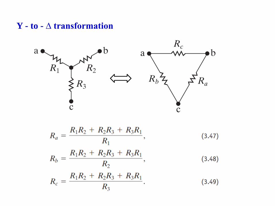
Y - to - ∆ transformation