Chapter 3 Lab 3-2, Multi-Area OSPF with Stub Areas...
7
Configuration and Management of Networks Multi-Area OSPF. The lab is built on the topology: Objectives ! Configure multiple-area OSPF on a router. ! Verify multiple-area behavior. Background You are responsible for configuring the new network to connect your company’s engineering, marketing, and accounting departments, represented by loopback interfaces on each of the three routers. The physical devices have just been installed and connected by serial cables. Configure multiple-area OSPF to allow full connectivity between all departments. R3 also has a loopback representing a connection to another autonomous system that is not part of OSPF. Note: This lab uses Cisco 1841 routers with Cisco IOS Release 12.4(24)T1 and the Advanced IP Services Step 1: Configure addressing and loopbacks. a. Using the addressing scheme in the diagram, apply IP addresses to the serial interfaces on R1, R2, and R3. Create loopbacks on R1, R2, and R3, and address them according to the diagram. Note: Depending on the router models you have, you might need to add clock rates to the DCE end of each connection (newer equipment adds this automatically). Verify connectivity across each serial link. R1# configure terminal Enter configuration commands, one per line. End with CNTL/Z. R1(config)# interface loopback 1 R1(config-if)# description Engineering Department R1(config-if)# ip address 10.1.1.1 255.255.255.0 R1(config-if)# interface serial 0/0/0 R1(config-if)# ip address 10.1.12.1 255.255.255.0 R1(config-if)# clockrate 64000 R1(config-if)# no shutdown R2# configure terminal Enter configuration commands, one per line. End with CNTL/Z. R2(config)# interface loopback 2 R2(config-if)# description Marketing Department R2(config-if)# ip address 10.1.2.1 255.255.255.0 R2(config-if)# interface serial 0/0/0
Transcript of Chapter 3 Lab 3-2, Multi-Area OSPF with Stub Areas...

Configuration and Management of Networks
Multi-Area OSPF. The lab is built on the topology:
All contents are Copyright © 1992–2010 Cisco Systems, Inc. All rights reserved. This document is Cisco Public Information. Page 1 of 16
CCNPv6 ROUTE
Chapter 3 Lab 3-2, Multi-Area OSPF with Stub Areas and Authentication
Topology
Objectives
! Configure multiple-area OSPF on a router.
! Verify multiple-area behavior.
! Configure OSPF stub, totally stubby, and not-so-stubby areas.
! Configure OSPF authentication.
Background
You are responsible for configuring the new network to connect your company’s engineering, marketing, and
accounting departments, represented by loopback interfaces on each of the three routers. The physical
devices have just been installed and connected by serial cables. Configure multiple-area OSPF to allow full
connectivity between all departments.
R3 also has a loopback representing a connection to another autonomous system that is not part of OSPF.
Note: This lab uses Cisco 1841 routers with Cisco IOS Release 12.4(24)T1 and the Advanced IP Services
image c1841-advipservicesk9-mz.124-24.T1.bin. You can use other routers (such as a 2801 or 2811) and
Cisco IOS Software versions if they have comparable capabilities and features. Depending on the router
CCNPv6 ROUTE
All contents are Copyright © 1992–2010 Cisco Systems, Inc. All rights reserved. This document is Cisco Public Information. Page 2 of 16
model and Cisco IOS Software version, the commands available and output produced might vary from what is
shown in this lab.
Required Resources
! 3 routers (Cisco 1841 with Cisco IOS Release 12.4(24)T1 Advanced IP Services or comparable)
! Serial and console cables
Step 1: Configure addressing and loopbacks.
a. Using the addressing scheme in the diagram, apply IP addresses to the serial interfaces on R1, R2, and
R3. Create loopbacks on R1, R2, and R3, and address them according to the diagram.
Note: Depending on the router models you have, you might need to add clock rates to the DCE end of
each connection (newer equipment adds this automatically). Verify connectivity across each serial link.
R1# configure terminal
Enter configuration commands, one per line. End with CNTL/Z. R1(config)# interface loopback 1
R1(config-if)# description Engineering Department
R1(config-if)# ip address 10.1.1.1 255.255.255.0
R1(config-if)# interface serial 0/0/0
R1(config-if)# ip address 10.1.12.1 255.255.255.0
R1(config-if)# clockrate 64000
R1(config-if)# no shutdown
R2# configure terminal
Enter configuration commands, one per line. End with CNTL/Z. R2(config)# interface loopback 2
R2(config-if)# description Marketing Department
R2(config-if)# ip address 10.1.2.1 255.255.255.0
R2(config-if)# interface serial 0/0/0
R2(config-if)# ip address 10.1.12.2 255.255.255.0
R2(config-if)# no shutdown
R2(config-if)# interface serial 0/0/1
R2(config-if)# ip address 10.1.23.2 255.255.255.0
R2(config-if)# clockrate 64000
R2(config-if)# no shutdown
R3# configure terminal
Enter configuration commands, one per line. End with CNTL/Z. R3(config)# interface loopback 3
R3(config-if)# description Accounting Department
R3(config-if)# ip address 10.1.3.1 255.255.255.0
R3(config-if)# interface loopback 20
R3(config-if)# description Connection to another AS
R3(config-if)# ip address 172.20.200.1 255.255.255.0
R3(config-if)# interface serial 0/0/1
R3(config-if)# ip address 10.1.23.3 255.255.255.0
R3(config-if)# no shutdown
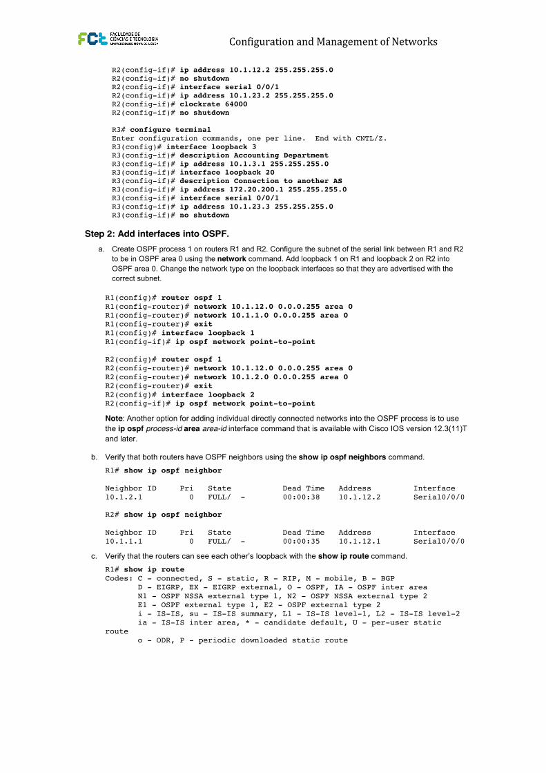
Step 2: Add interfaces into OSPF.
a. Create OSPF process 1 on routers R1 and R2. Configure the subnet of the serial link between R1 and R2
to be in OSPF area 0 using the network command. Add loopback 1 on R1 and loopback 2 on R2 into
OSPF area 0. Change the network type on the loopback interfaces so that they are advertised with the
correct subnet.
Configuration and Management of Networks
CCNPv6 ROUTE
All contents are Copyright © 1992–2010 Cisco Systems, Inc. All rights reserved. This document is Cisco Public Information. Page 2 of 16
model and Cisco IOS Software version, the commands available and output produced might vary from what is
shown in this lab.
Required Resources
! 3 routers (Cisco 1841 with Cisco IOS Release 12.4(24)T1 Advanced IP Services or comparable)
! Serial and console cables
Step 1: Configure addressing and loopbacks.
a. Using the addressing scheme in the diagram, apply IP addresses to the serial interfaces on R1, R2, and
R3. Create loopbacks on R1, R2, and R3, and address them according to the diagram.
Note: Depending on the router models you have, you might need to add clock rates to the DCE end of
each connection (newer equipment adds this automatically). Verify connectivity across each serial link.
R1# configure terminal
Enter configuration commands, one per line. End with CNTL/Z. R1(config)# interface loopback 1
R1(config-if)# description Engineering Department
R1(config-if)# ip address 10.1.1.1 255.255.255.0
R1(config-if)# interface serial 0/0/0
R1(config-if)# ip address 10.1.12.1 255.255.255.0
R1(config-if)# clockrate 64000
R1(config-if)# no shutdown
R2# configure terminal
Enter configuration commands, one per line. End with CNTL/Z. R2(config)# interface loopback 2
R2(config-if)# description Marketing Department
R2(config-if)# ip address 10.1.2.1 255.255.255.0
R2(config-if)# interface serial 0/0/0
R2(config-if)# ip address 10.1.12.2 255.255.255.0
R2(config-if)# no shutdown
R2(config-if)# interface serial 0/0/1
R2(config-if)# ip address 10.1.23.2 255.255.255.0
R2(config-if)# clockrate 64000
R2(config-if)# no shutdown
R3# configure terminal
Enter configuration commands, one per line. End with CNTL/Z. R3(config)# interface loopback 3
R3(config-if)# description Accounting Department
R3(config-if)# ip address 10.1.3.1 255.255.255.0
R3(config-if)# interface loopback 20
R3(config-if)# description Connection to another AS
R3(config-if)# ip address 172.20.200.1 255.255.255.0
R3(config-if)# interface serial 0/0/1
R3(config-if)# ip address 10.1.23.3 255.255.255.0
R3(config-if)# no shutdown
Step 2: Add interfaces into OSPF.
a. Create OSPF process 1 on routers R1 and R2. Configure the subnet of the serial link between R1 and R2
to be in OSPF area 0 using the network command. Add loopback 1 on R1 and loopback 2 on R2 into
OSPF area 0. Change the network type on the loopback interfaces so that they are advertised with the
correct subnet. CCNPv6 ROUTE
All contents are Copyright © 1992–2010 Cisco Systems, Inc. All rights reserved. This document is Cisco Public Information. Page 3 of 16
R1(config)# router ospf 1
R1(config-router)# network 10.1.12.0 0.0.0.255 area 0
R1(config-router)# network 10.1.1.0 0.0.0.255 area 0
R1(config-router)# exit
R1(config)# interface loopback 1
R1(config-if)# ip ospf network point-to-point
R2(config)# router ospf 1
R2(config-router)# network 10.1.12.0 0.0.0.255 area 0
R2(config-router)# network 10.1.2.0 0.0.0.255 area 0
R2(config-router)# exit
R2(config)# interface loopback 2
R2(config-if)# ip ospf network point-to-point
Note: Another option for adding individual directly connected networks into the OSPF process is to use
the ip ospf process-id area area-id interface command that is available with Cisco IOS version 12.3(11)T
and later.
b. Verify that both routers have OSPF neighbors using the show ip ospf neighbors command.
R1# show ip ospf neighbor
Neighbor ID Pri State Dead Time Address Interface
10.1.2.1 0 FULL/ - 00:00:38 10.1.12.2 Serial0/0/0
R2# show ip ospf neighbor
Neighbor ID Pri State Dead Time Address Interface
10.1.1.1 0 FULL/ - 00:00:35 10.1.12.1 Serial0/0/0
c. Verify that the routers can see each other’s loopback with the show ip route command.
R1# show ip route
Codes: C - connected, S - static, R - RIP, M - mobile, B - BGP
D - EIGRP, EX - EIGRP external, O - OSPF, IA - OSPF inter area
N1 - OSPF NSSA external type 1, N2 - OSPF NSSA external type 2
E1 - OSPF external type 1, E2 - OSPF external type 2
i - IS-IS, su - IS-IS summary, L1 - IS-IS level-1, L2 - IS-IS level-2
ia - IS-IS inter area, * - candidate default, U - per-user static
route
o - ODR, P - periodic downloaded static route
Gateway of last resort is not set
10.0.0.0/24 is subnetted, 3 subnets
C 10.1.12.0 is directly connected, Serial0/0/0 O 10.1.2.0 [110/65] via 10.1.12.2, 00:00:10, Serial0/0/0
C 10.1.1.0 is directly connected, Loopback1
R2# show ip route
Codes: C - connected, S - static, R - RIP, M - mobile, B - BGP
D - EIGRP, EX - EIGRP external, O - OSPF, IA - OSPF inter area
N1 - OSPF NSSA external type 1, N2 - OSPF NSSA external type 2
E1 - OSPF external type 1, E2 - OSPF external type 2
i - IS-IS, su - IS-IS summary, L1 - IS-IS level-1, L2 - IS-IS level-2
ia - IS-IS inter area, * - candidate default, U - per-user static
route
o - ODR, P - periodic downloaded static route
Gateway of last resort is not set
CCNPv6 ROUTE
All contents are Copyright © 1992–2010 Cisco Systems, Inc. All rights reserved. This document is Cisco Public Information. Page 3 of 16
R1(config)# router ospf 1
R1(config-router)# network 10.1.12.0 0.0.0.255 area 0
R1(config-router)# network 10.1.1.0 0.0.0.255 area 0
R1(config-router)# exit
R1(config)# interface loopback 1
R1(config-if)# ip ospf network point-to-point
R2(config)# router ospf 1
R2(config-router)# network 10.1.12.0 0.0.0.255 area 0
R2(config-router)# network 10.1.2.0 0.0.0.255 area 0
R2(config-router)# exit
R2(config)# interface loopback 2
R2(config-if)# ip ospf network point-to-point
Note: Another option for adding individual directly connected networks into the OSPF process is to use
the ip ospf process-id area area-id interface command that is available with Cisco IOS version 12.3(11)T
and later.
b. Verify that both routers have OSPF neighbors using the show ip ospf neighbors command.
R1# show ip ospf neighbor
Neighbor ID Pri State Dead Time Address Interface
10.1.2.1 0 FULL/ - 00:00:38 10.1.12.2 Serial0/0/0
R2# show ip ospf neighbor
Neighbor ID Pri State Dead Time Address Interface
10.1.1.1 0 FULL/ - 00:00:35 10.1.12.1 Serial0/0/0
c. Verify that the routers can see each other’s loopback with the show ip route command.
R1# show ip route
Codes: C - connected, S - static, R - RIP, M - mobile, B - BGP
D - EIGRP, EX - EIGRP external, O - OSPF, IA - OSPF inter area
N1 - OSPF NSSA external type 1, N2 - OSPF NSSA external type 2
E1 - OSPF external type 1, E2 - OSPF external type 2
i - IS-IS, su - IS-IS summary, L1 - IS-IS level-1, L2 - IS-IS level-2
ia - IS-IS inter area, * - candidate default, U - per-user static
route
o - ODR, P - periodic downloaded static route
Gateway of last resort is not set
10.0.0.0/24 is subnetted, 3 subnets
C 10.1.12.0 is directly connected, Serial0/0/0 O 10.1.2.0 [110/65] via 10.1.12.2, 00:00:10, Serial0/0/0
C 10.1.1.0 is directly connected, Loopback1
R2# show ip route
Codes: C - connected, S - static, R - RIP, M - mobile, B - BGP
D - EIGRP, EX - EIGRP external, O - OSPF, IA - OSPF inter area
N1 - OSPF NSSA external type 1, N2 - OSPF NSSA external type 2
E1 - OSPF external type 1, E2 - OSPF external type 2
i - IS-IS, su - IS-IS summary, L1 - IS-IS level-1, L2 - IS-IS level-2
ia - IS-IS inter area, * - candidate default, U - per-user static
route
o - ODR, P - periodic downloaded static route
Gateway of last resort is not set

Configuration and Management of Networks
CCNPv6 ROUTE
All contents are Copyright © 1992–2010 Cisco Systems, Inc. All rights reserved. This document is Cisco Public Information. Page 3 of 16
R1(config)# router ospf 1
R1(config-router)# network 10.1.12.0 0.0.0.255 area 0
R1(config-router)# network 10.1.1.0 0.0.0.255 area 0
R1(config-router)# exit
R1(config)# interface loopback 1
R1(config-if)# ip ospf network point-to-point
R2(config)# router ospf 1
R2(config-router)# network 10.1.12.0 0.0.0.255 area 0
R2(config-router)# network 10.1.2.0 0.0.0.255 area 0
R2(config-router)# exit
R2(config)# interface loopback 2
R2(config-if)# ip ospf network point-to-point
Note: Another option for adding individual directly connected networks into the OSPF process is to use
the ip ospf process-id area area-id interface command that is available with Cisco IOS version 12.3(11)T
and later.
b. Verify that both routers have OSPF neighbors using the show ip ospf neighbors command.
R1# show ip ospf neighbor
Neighbor ID Pri State Dead Time Address Interface
10.1.2.1 0 FULL/ - 00:00:38 10.1.12.2 Serial0/0/0
R2# show ip ospf neighbor
Neighbor ID Pri State Dead Time Address Interface
10.1.1.1 0 FULL/ - 00:00:35 10.1.12.1 Serial0/0/0
c. Verify that the routers can see each other’s loopback with the show ip route command.
R1# show ip route
Codes: C - connected, S - static, R - RIP, M - mobile, B - BGP
D - EIGRP, EX - EIGRP external, O - OSPF, IA - OSPF inter area
N1 - OSPF NSSA external type 1, N2 - OSPF NSSA external type 2
E1 - OSPF external type 1, E2 - OSPF external type 2
i - IS-IS, su - IS-IS summary, L1 - IS-IS level-1, L2 - IS-IS level-2
ia - IS-IS inter area, * - candidate default, U - per-user static
route
o - ODR, P - periodic downloaded static route
Gateway of last resort is not set
10.0.0.0/24 is subnetted, 3 subnets
C 10.1.12.0 is directly connected, Serial0/0/0 O 10.1.2.0 [110/65] via 10.1.12.2, 00:00:10, Serial0/0/0
C 10.1.1.0 is directly connected, Loopback1
R2# show ip route
Codes: C - connected, S - static, R - RIP, M - mobile, B - BGP
D - EIGRP, EX - EIGRP external, O - OSPF, IA - OSPF inter area
N1 - OSPF NSSA external type 1, N2 - OSPF NSSA external type 2
E1 - OSPF external type 1, E2 - OSPF external type 2
i - IS-IS, su - IS-IS summary, L1 - IS-IS level-1, L2 - IS-IS level-2
ia - IS-IS inter area, * - candidate default, U - per-user static
route
o - ODR, P - periodic downloaded static route
Gateway of last resort is not set
CCNPv6 ROUTE
All contents are Copyright © 1992–2010 Cisco Systems, Inc. All rights reserved. This document is Cisco Public Information. Page 4 of 16
10.0.0.0/24 is subnetted, 4 subnets
C 10.1.12.0 is directly connected, Serial0/0/0
C 10.1.2.0 is directly connected, Loopback2
O 10.1.1.0 [110/65] via 10.1.12.1, 00:00:30, Serial0/0/0
C 10.1.23.0 is directly connected, Serial0/0/1
d. Add the subnet between R2 and R3 into OSPF area 23 using the network command. Add loopback 3 on
R3 into area 23.
R2(config)# router ospf 1
R2(config-router)# network 10.1.23.0 0.0.0.255 area 23
R3(config)# router ospf 1
R3(config-router)# network 10.1.23.0 0.0.0.255 area 23
R3(config-router)# network 10.1.3.0 0.0.0.255 area 23
R3(config-router)# exit
R3(config)# interface loopback 3
R3(config-if)# ip ospf network point-to-point
e. Verify that this neighbor relationship comes up using the show ip ospf neighbors command.
R2# show ip ospf neighbor
Neighbor ID Pri State Dead Time Address Interface
10.1.1.1 0 FULL/ - 00:00:36 10.1.12.1 Serial0/0/0
10.1.3.1 0 FULL/ - 00:00:36 10.1.23.3 Serial0/0/1
f. If you look at the output of the show ip route command on R1, you see a route to the R3 loopback.
Notice that it is identified as an inter-area route.
R1# show ip route
Codes: C - connected, S - static, R - RIP, M - mobile, B - BGP
D - EIGRP, EX - EIGRP external, O - OSPF, IA - OSPF inter area
N1 - OSPF NSSA external type 1, N2 - OSPF NSSA external type 2
E1 - OSPF external type 1, E2 - OSPF external type 2
i - IS-IS, su - IS-IS summary, L1 - IS-IS level-1, L2 - IS-IS level-2
ia - IS-IS inter area, * - candidate default, U - per-user static
route
o - ODR, P - periodic downloaded static route
Gateway of last resort is not set
10.0.0.0/24 is subnetted, 5 subnets
C 10.1.12.0 is directly connected, Serial0/0/0 O IA 10.1.3.0 [110/129] via 10.1.12.2, 00:00:28, Serial0/0/0
O 10.1.2.0 [110/65] via 10.1.12.2, 00:01:38, Serial0/0/0
C 10.1.1.0 is directly connected, Loopback1
O IA 10.1.23.0 [110/128] via 10.1.12.2, 00:01:38, Serial0/0/0
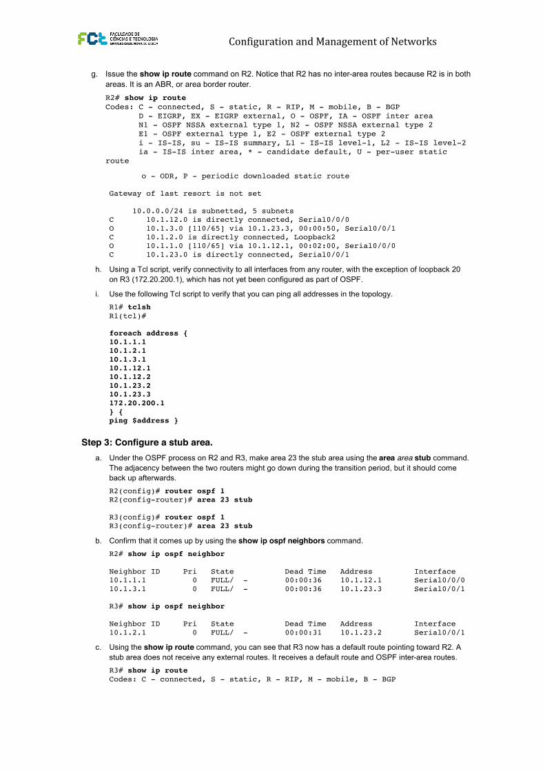
g. Issue the show ip route command on R2. Notice that R2 has no inter-area routes because R2 is in both
areas. It is an ABR, or area border router.
R2# show ip route
Codes: C - connected, S - static, R - RIP, M - mobile, B - BGP
D - EIGRP, EX - EIGRP external, O - OSPF, IA - OSPF inter area
N1 - OSPF NSSA external type 1, N2 - OSPF NSSA external type 2
E1 - OSPF external type 1, E2 - OSPF external type 2
i - IS-IS, su - IS-IS summary, L1 - IS-IS level-1, L2 - IS-IS level-2
ia - IS-IS inter area, * - candidate default, U - per-user static
route
CCNPv6 ROUTE
All contents are Copyright © 1992–2010 Cisco Systems, Inc. All rights reserved. This document is Cisco Public Information. Page 4 of 16
10.0.0.0/24 is subnetted, 4 subnets
C 10.1.12.0 is directly connected, Serial0/0/0
C 10.1.2.0 is directly connected, Loopback2
O 10.1.1.0 [110/65] via 10.1.12.1, 00:00:30, Serial0/0/0
C 10.1.23.0 is directly connected, Serial0/0/1
d. Add the subnet between R2 and R3 into OSPF area 23 using the network command. Add loopback 3 on
R3 into area 23.
R2(config)# router ospf 1
R2(config-router)# network 10.1.23.0 0.0.0.255 area 23
R3(config)# router ospf 1
R3(config-router)# network 10.1.23.0 0.0.0.255 area 23
R3(config-router)# network 10.1.3.0 0.0.0.255 area 23
R3(config-router)# exit
R3(config)# interface loopback 3
R3(config-if)# ip ospf network point-to-point
e. Verify that this neighbor relationship comes up using the show ip ospf neighbors command.
R2# show ip ospf neighbor
Neighbor ID Pri State Dead Time Address Interface
10.1.1.1 0 FULL/ - 00:00:36 10.1.12.1 Serial0/0/0
10.1.3.1 0 FULL/ - 00:00:36 10.1.23.3 Serial0/0/1
f. If you look at the output of the show ip route command on R1, you see a route to the R3 loopback.
Notice that it is identified as an inter-area route.
R1# show ip route
Codes: C - connected, S - static, R - RIP, M - mobile, B - BGP
D - EIGRP, EX - EIGRP external, O - OSPF, IA - OSPF inter area
N1 - OSPF NSSA external type 1, N2 - OSPF NSSA external type 2
E1 - OSPF external type 1, E2 - OSPF external type 2
i - IS-IS, su - IS-IS summary, L1 - IS-IS level-1, L2 - IS-IS level-2
ia - IS-IS inter area, * - candidate default, U - per-user static
route
o - ODR, P - periodic downloaded static route
Gateway of last resort is not set
10.0.0.0/24 is subnetted, 5 subnets
C 10.1.12.0 is directly connected, Serial0/0/0 O IA 10.1.3.0 [110/129] via 10.1.12.2, 00:00:28, Serial0/0/0
O 10.1.2.0 [110/65] via 10.1.12.2, 00:01:38, Serial0/0/0
C 10.1.1.0 is directly connected, Loopback1
O IA 10.1.23.0 [110/128] via 10.1.12.2, 00:01:38, Serial0/0/0
g. Issue the show ip route command on R2. Notice that R2 has no inter-area routes because R2 is in both
areas. It is an ABR, or area border router.
R2# show ip route
Codes: C - connected, S - static, R - RIP, M - mobile, B - BGP
D - EIGRP, EX - EIGRP external, O - OSPF, IA - OSPF inter area
N1 - OSPF NSSA external type 1, N2 - OSPF NSSA external type 2
E1 - OSPF external type 1, E2 - OSPF external type 2
i - IS-IS, su - IS-IS summary, L1 - IS-IS level-1, L2 - IS-IS level-2
ia - IS-IS inter area, * - candidate default, U - per-user static
route
Configuration and Management of Networks
CCNPv6 ROUTE
All contents are Copyright © 1992–2010 Cisco Systems, Inc. All rights reserved. This document is Cisco Public Information. Page 4 of 16
10.0.0.0/24 is subnetted, 4 subnets
C 10.1.12.0 is directly connected, Serial0/0/0
C 10.1.2.0 is directly connected, Loopback2
O 10.1.1.0 [110/65] via 10.1.12.1, 00:00:30, Serial0/0/0
C 10.1.23.0 is directly connected, Serial0/0/1
d. Add the subnet between R2 and R3 into OSPF area 23 using the network command. Add loopback 3 on
R3 into area 23.
R2(config)# router ospf 1
R2(config-router)# network 10.1.23.0 0.0.0.255 area 23
R3(config)# router ospf 1
R3(config-router)# network 10.1.23.0 0.0.0.255 area 23
R3(config-router)# network 10.1.3.0 0.0.0.255 area 23
R3(config-router)# exit
R3(config)# interface loopback 3
R3(config-if)# ip ospf network point-to-point
e. Verify that this neighbor relationship comes up using the show ip ospf neighbors command.
R2# show ip ospf neighbor
Neighbor ID Pri State Dead Time Address Interface
10.1.1.1 0 FULL/ - 00:00:36 10.1.12.1 Serial0/0/0
10.1.3.1 0 FULL/ - 00:00:36 10.1.23.3 Serial0/0/1
f. If you look at the output of the show ip route command on R1, you see a route to the R3 loopback.
Notice that it is identified as an inter-area route.
R1# show ip route
Codes: C - connected, S - static, R - RIP, M - mobile, B - BGP
D - EIGRP, EX - EIGRP external, O - OSPF, IA - OSPF inter area
N1 - OSPF NSSA external type 1, N2 - OSPF NSSA external type 2
E1 - OSPF external type 1, E2 - OSPF external type 2
i - IS-IS, su - IS-IS summary, L1 - IS-IS level-1, L2 - IS-IS level-2
ia - IS-IS inter area, * - candidate default, U - per-user static
route
o - ODR, P - periodic downloaded static route
Gateway of last resort is not set
10.0.0.0/24 is subnetted, 5 subnets
C 10.1.12.0 is directly connected, Serial0/0/0 O IA 10.1.3.0 [110/129] via 10.1.12.2, 00:00:28, Serial0/0/0
O 10.1.2.0 [110/65] via 10.1.12.2, 00:01:38, Serial0/0/0
C 10.1.1.0 is directly connected, Loopback1
O IA 10.1.23.0 [110/128] via 10.1.12.2, 00:01:38, Serial0/0/0
g. Issue the show ip route command on R2. Notice that R2 has no inter-area routes because R2 is in both
areas. It is an ABR, or area border router.
R2# show ip route
Codes: C - connected, S - static, R - RIP, M - mobile, B - BGP
D - EIGRP, EX - EIGRP external, O - OSPF, IA - OSPF inter area
N1 - OSPF NSSA external type 1, N2 - OSPF NSSA external type 2
E1 - OSPF external type 1, E2 - OSPF external type 2
i - IS-IS, su - IS-IS summary, L1 - IS-IS level-1, L2 - IS-IS level-2
ia - IS-IS inter area, * - candidate default, U - per-user static
route CCNPv6 ROUTE
All contents are Copyright © 1992–2010 Cisco Systems, Inc. All rights reserved. This document is Cisco Public Information. Page 5 of 16
o - ODR, P - periodic downloaded static route
Gateway of last resort is not set
10.0.0.0/24 is subnetted, 5 subnets
C 10.1.12.0 is directly connected, Serial0/0/0
O 10.1.3.0 [110/65] via 10.1.23.3, 00:00:50, Serial0/0/1
C 10.1.2.0 is directly connected, Loopback2
O 10.1.1.0 [110/65] via 10.1.12.1, 00:02:00, Serial0/0/0
C 10.1.23.0 is directly connected, Serial0/0/1
h. Using a Tcl script, verify connectivity to all interfaces from any router, with the exception of loopback 20
on R3 (172.20.200.1), which has not yet been configured as part of OSPF.
i. Use the following Tcl script to verify that you can ping all addresses in the topology.
R1# tclsh
R1(tcl)#
foreach address {
10.1.1.1
10.1.2.1
10.1.3.1
10.1.12.1
10.1.12.2
10.1.23.2
10.1.23.3
172.20.200.1
} {
ping $address }
Step 3: Configure a stub area.
a. Under the OSPF process on R2 and R3, make area 23 the stub area using the area area stub command.
The adjacency between the two routers might go down during the transition period, but it should come
back up afterwards.
R2(config)# router ospf 1
R2(config-router)# area 23 stub
R3(config)# router ospf 1
R3(config-router)# area 23 stub
b. Confirm that it comes up by using the show ip ospf neighbors command.
R2# show ip ospf neighbor
Neighbor ID Pri State Dead Time Address Interface
10.1.1.1 0 FULL/ - 00:00:36 10.1.12.1 Serial0/0/0
10.1.3.1 0 FULL/ - 00:00:36 10.1.23.3 Serial0/0/1
R3# show ip ospf neighbor
Neighbor ID Pri State Dead Time Address Interface
10.1.2.1 0 FULL/ - 00:00:31 10.1.23.2 Serial0/0/1
c. Using the show ip route command, you can see that R3 now has a default route pointing toward R2. A
stub area does not receive any external routes. It receives a default route and OSPF inter-area routes.
R3# show ip route
Codes: C - connected, S - static, R - RIP, M - mobile, B - BGP
CCNPv6 ROUTE
All contents are Copyright © 1992–2010 Cisco Systems, Inc. All rights reserved. This document is Cisco Public Information. Page 5 of 16
o - ODR, P - periodic downloaded static route
Gateway of last resort is not set
10.0.0.0/24 is subnetted, 5 subnets
C 10.1.12.0 is directly connected, Serial0/0/0
O 10.1.3.0 [110/65] via 10.1.23.3, 00:00:50, Serial0/0/1
C 10.1.2.0 is directly connected, Loopback2
O 10.1.1.0 [110/65] via 10.1.12.1, 00:02:00, Serial0/0/0
C 10.1.23.0 is directly connected, Serial0/0/1
h. Using a Tcl script, verify connectivity to all interfaces from any router, with the exception of loopback 20
on R3 (172.20.200.1), which has not yet been configured as part of OSPF.
i. Use the following Tcl script to verify that you can ping all addresses in the topology.
R1# tclsh
R1(tcl)#
foreach address {
10.1.1.1
10.1.2.1
10.1.3.1
10.1.12.1
10.1.12.2
10.1.23.2
10.1.23.3
172.20.200.1
} {
ping $address }
Step 3: Configure a stub area.
a. Under the OSPF process on R2 and R3, make area 23 the stub area using the area area stub command.
The adjacency between the two routers might go down during the transition period, but it should come
back up afterwards.
R2(config)# router ospf 1
R2(config-router)# area 23 stub
R3(config)# router ospf 1
R3(config-router)# area 23 stub
b. Confirm that it comes up by using the show ip ospf neighbors command.
R2# show ip ospf neighbor
Neighbor ID Pri State Dead Time Address Interface
10.1.1.1 0 FULL/ - 00:00:36 10.1.12.1 Serial0/0/0
10.1.3.1 0 FULL/ - 00:00:36 10.1.23.3 Serial0/0/1
R3# show ip ospf neighbor
Neighbor ID Pri State Dead Time Address Interface
10.1.2.1 0 FULL/ - 00:00:31 10.1.23.2 Serial0/0/1
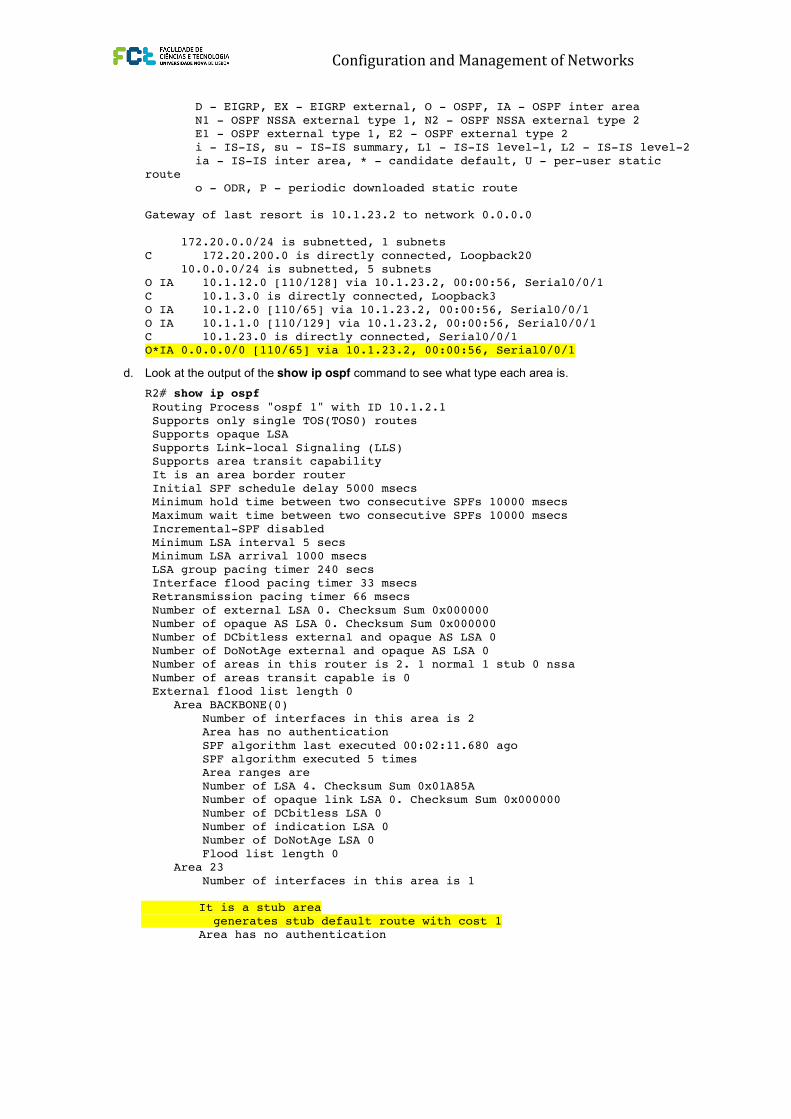
c. Using the show ip route command, you can see that R3 now has a default route pointing toward R2. A
stub area does not receive any external routes. It receives a default route and OSPF inter-area routes.
R3# show ip route
Codes: C - connected, S - static, R - RIP, M - mobile, B - BGP
Configuration and Management of Networks CCNPv6 ROUTE
All contents are Copyright © 1992–2010 Cisco Systems, Inc. All rights reserved. This document is Cisco Public Information. Page 6 of 16
D - EIGRP, EX - EIGRP external, O - OSPF, IA - OSPF inter area
N1 - OSPF NSSA external type 1, N2 - OSPF NSSA external type 2
E1 - OSPF external type 1, E2 - OSPF external type 2
i - IS-IS, su - IS-IS summary, L1 - IS-IS level-1, L2 - IS-IS level-2
ia - IS-IS inter area, * - candidate default, U - per-user static
route
o - ODR, P - periodic downloaded static route
Gateway of last resort is 10.1.23.2 to network 0.0.0.0
172.20.0.0/24 is subnetted, 1 subnets
C 172.20.200.0 is directly connected, Loopback20
10.0.0.0/24 is subnetted, 5 subnets
O IA 10.1.12.0 [110/128] via 10.1.23.2, 00:00:56, Serial0/0/1
C 10.1.3.0 is directly connected, Loopback3
O IA 10.1.2.0 [110/65] via 10.1.23.2, 00:00:56, Serial0/0/1
O IA 10.1.1.0 [110/129] via 10.1.23.2, 00:00:56, Serial0/0/1
C 10.1.23.0 is directly connected, Serial0/0/1 O*IA 0.0.0.0/0 [110/65] via 10.1.23.2, 00:00:56, Serial0/0/1
d. Look at the output of the show ip ospf command to see what type each area is.
R2# show ip ospf
Routing Process "ospf 1" with ID 10.1.2.1
Supports only single TOS(TOS0) routes
Supports opaque LSA
Supports Link-local Signaling (LLS)
Supports area transit capability
It is an area border router
Initial SPF schedule delay 5000 msecs
Minimum hold time between two consecutive SPFs 10000 msecs
Maximum wait time between two consecutive SPFs 10000 msecs
Incremental-SPF disabled
Minimum LSA interval 5 secs
Minimum LSA arrival 1000 msecs
LSA group pacing timer 240 secs
Interface flood pacing timer 33 msecs
Retransmission pacing timer 66 msecs
Number of external LSA 0. Checksum Sum 0x000000
Number of opaque AS LSA 0. Checksum Sum 0x000000
Number of DCbitless external and opaque AS LSA 0
Number of DoNotAge external and opaque AS LSA 0
Number of areas in this router is 2. 1 normal 1 stub 0 nssa
Number of areas transit capable is 0
External flood list length 0
Area BACKBONE(0)
Number of interfaces in this area is 2
Area has no authentication
SPF algorithm last executed 00:02:11.680 ago
SPF algorithm executed 5 times
Area ranges are
Number of LSA 4. Checksum Sum 0x01A85A
Number of opaque link LSA 0. Checksum Sum 0x000000
Number of DCbitless LSA 0
Number of indication LSA 0
Number of DoNotAge LSA 0
Flood list length 0
Area 23
Number of interfaces in this area is 1 CCNPv6 ROUTE
All contents are Copyright © 1992–2010 Cisco Systems, Inc. All rights reserved. This document is Cisco Public Information. Page 7 of 16
It is a stub area
generates stub default route with cost 1
Area has no authentication
SPF algorithm last executed 00:01:38.276 ago
SPF algorithm executed 8 times
Area ranges are
Number of LSA 6. Checksum Sum 0x027269
Number of opaque link LSA 0. Checksum Sum 0x000000
Number of DCbitless LSA 0
Number of indication LSA 0
Number of DoNotAge LSA 0
Flood list length 0
What are the advantages of having a router receive a default route rather than a more specific route?
_______________________________________________________________________________
_______________________________________________________________________________
Why do all routers in a stub area need to know that the area is a stub?
_______________________________________________________________________________
_______________________________________________________________________________
_______________________________________________________________________________
Step 4: Configure a totally stubby area.
A modified version of a stubby area is a totally stubby area. A totally stubby area ABR only allows in a single,
default route from the backbone. To configure a totally stubby area, you only need to change a command at
the ABR, R2 in this scenario. Under the router OSPF process, you will enter the area 23 stub no-summary
command to replace the existing stub command for area 23. The no-summary option tells the router that this
area will not receive summary (inter-area) routes.
a. To see how this works, issue the show ip route command on R3. Notice the inter-area routes, in addition
to the default route generated by R2.
R3# show ip route
Codes: C - connected, S - static, R - RIP, M - mobile, B - BGP
D - EIGRP, EX - EIGRP external, O - OSPF, IA - OSPF inter area
N1 - OSPF NSSA external type 1, N2 - OSPF NSSA external type 2
E1 - OSPF external type 1, E2 - OSPF external type 2
i - IS-IS, su - IS-IS summary, L1 - IS-IS level-1, L2 - IS-IS level-2
ia - IS-IS inter area, * - candidate default, U - per-user static
route
o - ODR, P - periodic downloaded static route
Gateway of last resort is 10.1.23.2 to network 0.0.0.0
172.20.0.0/24 is subnetted, 1 subnets
C 172.20.200.0 is directly connected, Loopback20
10.0.0.0/24 is subnetted, 5 subnets
O IA 10.1.12.0 [110/128] via 10.1.23.2, 00:00:56, Serial0/0/1
C 10.1.3.0 is directly connected, Loopback3
O IA 10.1.2.0 [110/65] via 10.1.23.2, 00:00:56, Serial0/0/1
O IA 10.1.1.0 [110/129] via 10.1.23.2, 00:00:56, Serial0/0/1
C 10.1.23.0 is directly connected, Serial0/0/1
O*IA 0.0.0.0/0 [110/65] via 10.1.23.2, 00:00:56, Serial0/0/1

Configuration and Management of Networks
CCNPv6 ROUTE
All contents are Copyright © 1992–2010 Cisco Systems, Inc. All rights reserved. This document is Cisco Public Information. Page 7 of 16
It is a stub area
generates stub default route with cost 1
Area has no authentication
SPF algorithm last executed 00:01:38.276 ago
SPF algorithm executed 8 times
Area ranges are
Number of LSA 6. Checksum Sum 0x027269
Number of opaque link LSA 0. Checksum Sum 0x000000
Number of DCbitless LSA 0
Number of indication LSA 0
Number of DoNotAge LSA 0
Flood list length 0
What are the advantages of having a router receive a default route rather than a more specific route?
_______________________________________________________________________________
_______________________________________________________________________________
Why do all routers in a stub area need to know that the area is a stub?
_______________________________________________________________________________
_______________________________________________________________________________
_______________________________________________________________________________
Step 4: Configure a totally stubby area.
A modified version of a stubby area is a totally stubby area. A totally stubby area ABR only allows in a single,
default route from the backbone. To configure a totally stubby area, you only need to change a command at
the ABR, R2 in this scenario. Under the router OSPF process, you will enter the area 23 stub no-summary
command to replace the existing stub command for area 23. The no-summary option tells the router that this
area will not receive summary (inter-area) routes.
a. To see how this works, issue the show ip route command on R3. Notice the inter-area routes, in addition
to the default route generated by R2.
R3# show ip route
Codes: C - connected, S - static, R - RIP, M - mobile, B - BGP
D - EIGRP, EX - EIGRP external, O - OSPF, IA - OSPF inter area
N1 - OSPF NSSA external type 1, N2 - OSPF NSSA external type 2
E1 - OSPF external type 1, E2 - OSPF external type 2
i - IS-IS, su - IS-IS summary, L1 - IS-IS level-1, L2 - IS-IS level-2
ia - IS-IS inter area, * - candidate default, U - per-user static
route
o - ODR, P - periodic downloaded static route
Gateway of last resort is 10.1.23.2 to network 0.0.0.0
172.20.0.0/24 is subnetted, 1 subnets
C 172.20.200.0 is directly connected, Loopback20
10.0.0.0/24 is subnetted, 5 subnets
O IA 10.1.12.0 [110/128] via 10.1.23.2, 00:00:56, Serial0/0/1
C 10.1.3.0 is directly connected, Loopback3
O IA 10.1.2.0 [110/65] via 10.1.23.2, 00:00:56, Serial0/0/1
O IA 10.1.1.0 [110/129] via 10.1.23.2, 00:00:56, Serial0/0/1
C 10.1.23.0 is directly connected, Serial0/0/1
O*IA 0.0.0.0/0 [110/65] via 10.1.23.2, 00:00:56, Serial0/0/1
CCNPv6 ROUTE
All contents are Copyright © 1992–2010 Cisco Systems, Inc. All rights reserved. This document is Cisco Public Information. Page 7 of 16
It is a stub area
generates stub default route with cost 1
Area has no authentication
SPF algorithm last executed 00:01:38.276 ago
SPF algorithm executed 8 times
Area ranges are
Number of LSA 6. Checksum Sum 0x027269
Number of opaque link LSA 0. Checksum Sum 0x000000
Number of DCbitless LSA 0
Number of indication LSA 0
Number of DoNotAge LSA 0
Flood list length 0
What are the advantages of having a router receive a default route rather than a more specific route?
_______________________________________________________________________________
_______________________________________________________________________________
Why do all routers in a stub area need to know that the area is a stub?
_______________________________________________________________________________
_______________________________________________________________________________
_______________________________________________________________________________
Step 4: Configure a totally stubby area.
A modified version of a stubby area is a totally stubby area. A totally stubby area ABR only allows in a single,
default route from the backbone. To configure a totally stubby area, you only need to change a command at
the ABR, R2 in this scenario. Under the router OSPF process, you will enter the area 23 stub no-summary
command to replace the existing stub command for area 23. The no-summary option tells the router that this
area will not receive summary (inter-area) routes.
a. To see how this works, issue the show ip route command on R3. Notice the inter-area routes, in addition
to the default route generated by R2.
R3# show ip route
Codes: C - connected, S - static, R - RIP, M - mobile, B - BGP
D - EIGRP, EX - EIGRP external, O - OSPF, IA - OSPF inter area
N1 - OSPF NSSA external type 1, N2 - OSPF NSSA external type 2
E1 - OSPF external type 1, E2 - OSPF external type 2
i - IS-IS, su - IS-IS summary, L1 - IS-IS level-1, L2 - IS-IS level-2
ia - IS-IS inter area, * - candidate default, U - per-user static
route
o - ODR, P - periodic downloaded static route
Gateway of last resort is 10.1.23.2 to network 0.0.0.0
172.20.0.0/24 is subnetted, 1 subnets
C 172.20.200.0 is directly connected, Loopback20
10.0.0.0/24 is subnetted, 5 subnets
O IA 10.1.12.0 [110/128] via 10.1.23.2, 00:00:56, Serial0/0/1
C 10.1.3.0 is directly connected, Loopback3
O IA 10.1.2.0 [110/65] via 10.1.23.2, 00:00:56, Serial0/0/1
O IA 10.1.1.0 [110/129] via 10.1.23.2, 00:00:56, Serial0/0/1
C 10.1.23.0 is directly connected, Serial0/0/1
O*IA 0.0.0.0/0 [110/65] via 10.1.23.2, 00:00:56, Serial0/0/1 CCNPv6 ROUTE
All contents are Copyright © 1992–2010 Cisco Systems, Inc. All rights reserved. This document is Cisco Public Information. Page 8 of 16
b. Look at the output of the show ip ospf database command on R2 to see which LSAs are in its OSPF
database.
R2# show ip ospf database
OSPF Router with ID (10.1.2.1) (Process ID 1)
Router Link States (Area 0)
Link ID ADV Router Age Seq# Checksum Link count
10.1.1.1 10.1.1.1 435 0x80000004 0x0056D6 3
10.1.2.1 10.1.2.1 358 0x80000003 0x0057D2 3
Summary Net Link States (Area 0)
Link ID ADV Router Age Seq# Checksum
10.1.3.0 10.1.2.1 174 0x80000001 0x00EFEF
10.1.23.0 10.1.2.1 354 0x80000001 0x0009C3
Router Link States (Area 23)
Link ID ADV Router Age Seq# Checksum Link count
10.1.2.1 10.1.2.1 188 0x80000004 0x00298C 2
10.1.3.1 10.1.3.1 188 0x80000004 0x00B762 3
Summary Net Link States (Area 23)
Link ID ADV Router Age Seq# Checksum
0.0.0.0 10.1.2.1 207 0x80000001 0x003BF4
10.1.1.0 10.1.2.1 209 0x80000002 0x0022C0
10.1.2.0 10.1.2.1 209 0x80000002 0x00948D
10.1.12.0 10.1.2.1 209 0x80000002 0x009E3A
c. Enter the stub no-summary command on R2 (the ABR) under the OSPF process.
R2(config)# router ospf 1
R2(config-router)# area 23 stub no-summary
d. Go back to R3 and issue the show ip route command again. Notice that it shows only one incoming
route from OSPF.
R3# show ip route
Codes: C - connected, S - static, R - RIP, M - mobile, B - BGP
D - EIGRP, EX - EIGRP external, O - OSPF, IA - OSPF inter area
N1 - OSPF NSSA external type 1, N2 - OSPF NSSA external type 2
E1 - OSPF external type 1, E2 - OSPF external type 2
i - IS-IS, su - IS-IS summary, L1 - IS-IS level-1, L2 - IS-IS level-2
ia - IS-IS inter area, * - candidate default, U - per-user static
route
o - ODR, P - periodic downloaded static route
Gateway of last resort is 10.1.23.2 to network 0.0.0.0
172.20.0.0/24 is subnetted, 1 subnets
C 172.20.200.0 is directly connected, Loopback20
10.0.0.0/24 is subnetted, 2 subnets
C 10.1.3.0 is directly connected, Loopback3
C 10.1.23.0 is directly connected, Serial0/0/1 O*IA 0.0.0.0/0 [110/65] via 10.1.23.2, 00:00:10, Serial0/0/1

Configuration and Management of Networks
CCNPv6 ROUTE
All contents are Copyright © 1992–2010 Cisco Systems, Inc. All rights reserved. This document is Cisco Public Information. Page 8 of 16
b. Look at the output of the show ip ospf database command on R2 to see which LSAs are in its OSPF
database.
R2# show ip ospf database
OSPF Router with ID (10.1.2.1) (Process ID 1)
Router Link States (Area 0)
Link ID ADV Router Age Seq# Checksum Link count
10.1.1.1 10.1.1.1 435 0x80000004 0x0056D6 3
10.1.2.1 10.1.2.1 358 0x80000003 0x0057D2 3
Summary Net Link States (Area 0)
Link ID ADV Router Age Seq# Checksum
10.1.3.0 10.1.2.1 174 0x80000001 0x00EFEF
10.1.23.0 10.1.2.1 354 0x80000001 0x0009C3
Router Link States (Area 23)
Link ID ADV Router Age Seq# Checksum Link count
10.1.2.1 10.1.2.1 188 0x80000004 0x00298C 2
10.1.3.1 10.1.3.1 188 0x80000004 0x00B762 3
Summary Net Link States (Area 23)
Link ID ADV Router Age Seq# Checksum
0.0.0.0 10.1.2.1 207 0x80000001 0x003BF4
10.1.1.0 10.1.2.1 209 0x80000002 0x0022C0
10.1.2.0 10.1.2.1 209 0x80000002 0x00948D
10.1.12.0 10.1.2.1 209 0x80000002 0x009E3A
c. Enter the stub no-summary command on R2 (the ABR) under the OSPF process.
R2(config)# router ospf 1
R2(config-router)# area 23 stub no-summary
d. Go back to R3 and issue the show ip route command again. Notice that it shows only one incoming
route from OSPF.
R3# show ip route
Codes: C - connected, S - static, R - RIP, M - mobile, B - BGP
D - EIGRP, EX - EIGRP external, O - OSPF, IA - OSPF inter area
N1 - OSPF NSSA external type 1, N2 - OSPF NSSA external type 2
E1 - OSPF external type 1, E2 - OSPF external type 2
i - IS-IS, su - IS-IS summary, L1 - IS-IS level-1, L2 - IS-IS level-2
ia - IS-IS inter area, * - candidate default, U - per-user static
route
o - ODR, P - periodic downloaded static route
Gateway of last resort is 10.1.23.2 to network 0.0.0.0
172.20.0.0/24 is subnetted, 1 subnets
C 172.20.200.0 is directly connected, Loopback20
10.0.0.0/24 is subnetted, 2 subnets
C 10.1.3.0 is directly connected, Loopback3
C 10.1.23.0 is directly connected, Serial0/0/1 O*IA 0.0.0.0/0 [110/65] via 10.1.23.2, 00:00:10, Serial0/0/1 CCNPv6 ROUTE
All contents are Copyright © 1992–2010 Cisco Systems, Inc. All rights reserved. This document is Cisco Public Information. Page 9 of 16
e. Look at the show ip ospf database output to see which routes are in area 23.
R3# show ip ospf database
OSPF Router with ID (10.1.3.1) (Process ID 1)
Router Link States (Area 23)
Link ID ADV Router Age Seq# Checksum Link count
10.1.2.1 10.1.2.1 275 0x80000004 0x00298C 2
10.1.3.1 10.1.3.1 276 0x80000004 0x00B762 3
Summary Net Link States (Area 23)
Link ID ADV Router Age Seq# Checksum
0.0.0.0 10.1.2.1 68 0x80000002 0x0039F5
What are the advantages of making an area totally stubby instead of a regular stub area? What are the
disadvantages?
_______________________________________________________________________________
_______________________________________________________________________________
_______________________________________________________________________________
_______________________________________________________________________________
Why did only the ABR need to know that the area was totally stubby rather than all routers in the area?
_______________________________________________________________________________
_______________________________________________________________________________
_______________________________________________________________________________
Step 5: Configure a not-so-stubby area.
Not-so-stubby areas (NSSAs) are similar to regular stub areas, except that they allow routes to be
redistributed from an ASBR into that area with a special LSA type, which gets converted to a normal external
route at the ABR.
a. Change area 23 into an NSSA. NSSAs are not compatible with stub areas, so the first thing to do is issue
the no area 23 stub command on routers R2 and R3. Next, issue the area area nssa command on
routers R2 and R3 to change area 23 to an NSSA. To generate an external route into the NSSA, use the
redistribute connected subnets command on R3. This adds the previously unreachable loopback 20
into OSPF. Be sure to include the subnets keyword; otherwise, only classful networks are redistributed.
R2(config)# router ospf 1
R2(config-router)# no area 23 stub
R2(config-router)# area 23 nssa
R3(config)# router ospf 1
R3(config-router)# no area 23 stub
R3(config-router)# area 23 nssa
R3(config-router)# redistribute connected subnets
b. In the output of the show ip ospf command on R2, notice that area 23 is an NSSA and that R2 is
performing the LSA type 7 to type 5 translation. If there are multiple ABRs to an NSSA, the ABR with the
highest router ID performs the translation.
CCNPv6 ROUTE
All contents are Copyright © 1992–2010 Cisco Systems, Inc. All rights reserved. This document is Cisco Public Information. Page 12 of 16
172.20.0.0/24 is subnetted, 1 subnets
C 172.20.200.0 is directly connected, Loopback20
10.0.0.0/24 is subnetted, 5 subnets
O IA 10.1.12.0 [110/128] via 10.1.23.2, 00:02:11, Serial0/0/1
C 10.1.3.0 is directly connected, Loopback3
O IA 10.1.2.0 [110/65] via 10.1.23.2, 00:02:11, Serial0/0/1
O IA 10.1.1.0 [110/129] via 10.1.23.2, 00:02:11, Serial0/0/1
C 10.1.23.0 is directly connected, Serial0/0/1
f. Yet another type of area is a totally-stubby NSSA that combines the property of an NSSA area (injecting
external routing information into OSPF) with a totally stubby behavior (accepting only default route from
the backbone). Issue the area 23 nssa no-summary command on R2, similar to converting a stub area
into a totally stubby area.
R2(config)# router ospf 1
R2(config-router)# area 23 nssa no-summary
g. Check the routing table on R3. Notice that the inter-area routes have been replaced by a single default
route.
R3# show ip route
Codes: C - connected, S - static, R - RIP, M - mobile, B - BGP
D - EIGRP, EX - EIGRP external, O - OSPF, IA - OSPF inter area
N1 - OSPF NSSA external type 1, N2 - OSPF NSSA external type 2
E1 - OSPF external type 1, E2 - OSPF external type 2
i - IS-IS, su - IS-IS summary, L1 - IS-IS level-1, L2 - IS-IS level-2
ia - IS-IS inter area, * - candidate default, U - per-user static
route
o - ODR, P - periodic downloaded static route
Gateway of last resort is 10.1.23.2 to network 0.0.0.0
172.20.0.0/24 is subnetted, 1 subnets
C 172.20.200.0 is directly connected, Loopback20
10.0.0.0/24 is subnetted, 2 subnets
C 10.1.3.0 is directly connected, Loopback3
C 10.1.23.0 is directly connected, Serial0/0/1 O*IA 0.0.0.0/0 [110/65] via 10.1.23.2, 00:00:20, Serial0/0/1
h. On R2, look at the show ip ospf database output to see the various LSA types.
R2# show ip ospf database
OSPF Router with ID (10.1.2.1) (Process ID 1)
Router Link States (Area 0)
Link ID ADV Router Age Seq# Checksum Link count
10.1.1.1 10.1.1.1 944 0x80000004 0x0056D6 3
10.1.2.1 10.1.2.1 383 0x80000004 0x005BCB 3
Summary Net Link States (Area 0)
Link ID ADV Router Age Seq# Checksum
10.1.3.0 10.1.2.1 242 0x80000001 0x00EFEF
10.1.23.0 10.1.2.1 862 0x80000001 0x0009C3
Router Link States (Area 23)
Link ID ADV Router Age Seq# Checksum Link count


![JunOSluk.kis.p.lodz.pl/KSBG/wyklad/v2017/02 JUNIPER... · Juniper - JunOS 22 [edit] user@router# edit protocols ospf area 51 stub [edit protocols ospf area 0.0.0.51 stub] user@router#](https://static.fdocuments.net/doc/165x107/6110e194f9d81657a43878bc/juniper-juniper-junos-22-edit-userrouter-edit-protocols-ospf-area-51.jpg)